EP3751299B1 - Detecting latent faults within a cell of an energy storage system - Google Patents
Detecting latent faults within a cell of an energy storage system Download PDFInfo
- Publication number
- EP3751299B1 EP3751299B1 EP19179436.1A EP19179436A EP3751299B1 EP 3751299 B1 EP3751299 B1 EP 3751299B1 EP 19179436 A EP19179436 A EP 19179436A EP 3751299 B1 EP3751299 B1 EP 3751299B1
- Authority
- EP
- European Patent Office
- Prior art keywords
- cell
- selected cell
- ocv
- sohcc
- soc
- Prior art date
- Legal status (The legal status is an assumption and is not a legal conclusion. Google has not performed a legal analysis and makes no representation as to the accuracy of the status listed.)
- Active
Links
- 238000004146 energy storage Methods 0.000 title claims description 17
- 238000000034 method Methods 0.000 claims description 33
- 238000004590 computer program Methods 0.000 claims description 12
- 238000012545 processing Methods 0.000 claims description 11
- 238000001514 detection method Methods 0.000 claims description 7
- 230000002250 progressing effect Effects 0.000 claims description 2
- 230000011664 signaling Effects 0.000 claims 1
- 230000001771 impaired effect Effects 0.000 description 5
- 238000005259 measurement Methods 0.000 description 5
- HBBGRARXTFLTSG-UHFFFAOYSA-N Lithium ion Chemical compound [Li+] HBBGRARXTFLTSG-UHFFFAOYSA-N 0.000 description 3
- 229910001416 lithium ion Inorganic materials 0.000 description 3
- 230000002269 spontaneous effect Effects 0.000 description 3
- 238000004891 communication Methods 0.000 description 2
- 238000012544 monitoring process Methods 0.000 description 2
- 230000005540 biological transmission Effects 0.000 description 1
- OJIJEKBXJYRIBZ-UHFFFAOYSA-N cadmium nickel Chemical compound [Ni].[Cd] OJIJEKBXJYRIBZ-UHFFFAOYSA-N 0.000 description 1
- 230000007613 environmental effect Effects 0.000 description 1
- 229910052987 metal hydride Inorganic materials 0.000 description 1
- 239000007787 solid Substances 0.000 description 1
Images


Classifications
-
- G—PHYSICS
- G01—MEASURING; TESTING
- G01R—MEASURING ELECTRIC VARIABLES; MEASURING MAGNETIC VARIABLES
- G01R31/00—Arrangements for testing electric properties; Arrangements for locating electric faults; Arrangements for electrical testing characterised by what is being tested not provided for elsewhere
- G01R31/36—Arrangements for testing, measuring or monitoring the electrical condition of accumulators or electric batteries, e.g. capacity or state of charge [SoC]
- G01R31/385—Arrangements for measuring battery or accumulator variables
- G01R31/387—Determining ampere-hour charge capacity or SoC
- G01R31/388—Determining ampere-hour charge capacity or SoC involving voltage measurements
-
- G—PHYSICS
- G01—MEASURING; TESTING
- G01R—MEASURING ELECTRIC VARIABLES; MEASURING MAGNETIC VARIABLES
- G01R31/00—Arrangements for testing electric properties; Arrangements for locating electric faults; Arrangements for electrical testing characterised by what is being tested not provided for elsewhere
- G01R31/36—Arrangements for testing, measuring or monitoring the electrical condition of accumulators or electric batteries, e.g. capacity or state of charge [SoC]
- G01R31/392—Determining battery ageing or deterioration, e.g. state of health
-
- G—PHYSICS
- G01—MEASURING; TESTING
- G01R—MEASURING ELECTRIC VARIABLES; MEASURING MAGNETIC VARIABLES
- G01R31/00—Arrangements for testing electric properties; Arrangements for locating electric faults; Arrangements for electrical testing characterised by what is being tested not provided for elsewhere
- G01R31/36—Arrangements for testing, measuring or monitoring the electrical condition of accumulators or electric batteries, e.g. capacity or state of charge [SoC]
- G01R31/367—Software therefor, e.g. for battery testing using modelling or look-up tables
-
- B—PERFORMING OPERATIONS; TRANSPORTING
- B60—VEHICLES IN GENERAL
- B60L—PROPULSION OF ELECTRICALLY-PROPELLED VEHICLES; SUPPLYING ELECTRIC POWER FOR AUXILIARY EQUIPMENT OF ELECTRICALLY-PROPELLED VEHICLES; ELECTRODYNAMIC BRAKE SYSTEMS FOR VEHICLES IN GENERAL; MAGNETIC SUSPENSION OR LEVITATION FOR VEHICLES; MONITORING OPERATING VARIABLES OF ELECTRICALLY-PROPELLED VEHICLES; ELECTRIC SAFETY DEVICES FOR ELECTRICALLY-PROPELLED VEHICLES
- B60L3/00—Electric devices on electrically-propelled vehicles for safety purposes; Monitoring operating variables, e.g. speed, deceleration or energy consumption
- B60L3/0023—Detecting, eliminating, remedying or compensating for drive train abnormalities, e.g. failures within the drive train
- B60L3/0046—Detecting, eliminating, remedying or compensating for drive train abnormalities, e.g. failures within the drive train relating to electric energy storage systems, e.g. batteries or capacitors
-
- B—PERFORMING OPERATIONS; TRANSPORTING
- B60—VEHICLES IN GENERAL
- B60L—PROPULSION OF ELECTRICALLY-PROPELLED VEHICLES; SUPPLYING ELECTRIC POWER FOR AUXILIARY EQUIPMENT OF ELECTRICALLY-PROPELLED VEHICLES; ELECTRODYNAMIC BRAKE SYSTEMS FOR VEHICLES IN GENERAL; MAGNETIC SUSPENSION OR LEVITATION FOR VEHICLES; MONITORING OPERATING VARIABLES OF ELECTRICALLY-PROPELLED VEHICLES; ELECTRIC SAFETY DEVICES FOR ELECTRICALLY-PROPELLED VEHICLES
- B60L58/00—Methods or circuit arrangements for monitoring or controlling batteries or fuel cells, specially adapted for electric vehicles
- B60L58/10—Methods or circuit arrangements for monitoring or controlling batteries or fuel cells, specially adapted for electric vehicles for monitoring or controlling batteries
- B60L58/12—Methods or circuit arrangements for monitoring or controlling batteries or fuel cells, specially adapted for electric vehicles for monitoring or controlling batteries responding to state of charge [SoC]
-
- B—PERFORMING OPERATIONS; TRANSPORTING
- B60—VEHICLES IN GENERAL
- B60L—PROPULSION OF ELECTRICALLY-PROPELLED VEHICLES; SUPPLYING ELECTRIC POWER FOR AUXILIARY EQUIPMENT OF ELECTRICALLY-PROPELLED VEHICLES; ELECTRODYNAMIC BRAKE SYSTEMS FOR VEHICLES IN GENERAL; MAGNETIC SUSPENSION OR LEVITATION FOR VEHICLES; MONITORING OPERATING VARIABLES OF ELECTRICALLY-PROPELLED VEHICLES; ELECTRIC SAFETY DEVICES FOR ELECTRICALLY-PROPELLED VEHICLES
- B60L58/00—Methods or circuit arrangements for monitoring or controlling batteries or fuel cells, specially adapted for electric vehicles
- B60L58/10—Methods or circuit arrangements for monitoring or controlling batteries or fuel cells, specially adapted for electric vehicles for monitoring or controlling batteries
- B60L58/16—Methods or circuit arrangements for monitoring or controlling batteries or fuel cells, specially adapted for electric vehicles for monitoring or controlling batteries responding to battery ageing, e.g. to the number of charging cycles or the state of health [SoH]
-
- G—PHYSICS
- G01—MEASURING; TESTING
- G01R—MEASURING ELECTRIC VARIABLES; MEASURING MAGNETIC VARIABLES
- G01R31/00—Arrangements for testing electric properties; Arrangements for locating electric faults; Arrangements for electrical testing characterised by what is being tested not provided for elsewhere
- G01R31/36—Arrangements for testing, measuring or monitoring the electrical condition of accumulators or electric batteries, e.g. capacity or state of charge [SoC]
- G01R31/3644—Constructional arrangements
- G01R31/3648—Constructional arrangements comprising digital calculation means, e.g. for performing an algorithm
-
- G—PHYSICS
- G01—MEASURING; TESTING
- G01R—MEASURING ELECTRIC VARIABLES; MEASURING MAGNETIC VARIABLES
- G01R31/00—Arrangements for testing electric properties; Arrangements for locating electric faults; Arrangements for electrical testing characterised by what is being tested not provided for elsewhere
- G01R31/36—Arrangements for testing, measuring or monitoring the electrical condition of accumulators or electric batteries, e.g. capacity or state of charge [SoC]
- G01R31/371—Arrangements for testing, measuring or monitoring the electrical condition of accumulators or electric batteries, e.g. capacity or state of charge [SoC] with remote indication, e.g. on external chargers
-
- G—PHYSICS
- G01—MEASURING; TESTING
- G01R—MEASURING ELECTRIC VARIABLES; MEASURING MAGNETIC VARIABLES
- G01R31/00—Arrangements for testing electric properties; Arrangements for locating electric faults; Arrangements for electrical testing characterised by what is being tested not provided for elsewhere
- G01R31/36—Arrangements for testing, measuring or monitoring the electrical condition of accumulators or electric batteries, e.g. capacity or state of charge [SoC]
- G01R31/382—Arrangements for monitoring battery or accumulator variables, e.g. SoC
- G01R31/3835—Arrangements for monitoring battery or accumulator variables, e.g. SoC involving only voltage measurements
-
- G—PHYSICS
- G01—MEASURING; TESTING
- G01R—MEASURING ELECTRIC VARIABLES; MEASURING MAGNETIC VARIABLES
- G01R31/00—Arrangements for testing electric properties; Arrangements for locating electric faults; Arrangements for electrical testing characterised by what is being tested not provided for elsewhere
- G01R31/36—Arrangements for testing, measuring or monitoring the electrical condition of accumulators or electric batteries, e.g. capacity or state of charge [SoC]
- G01R31/389—Measuring internal impedance, internal conductance or related variables
-
- G—PHYSICS
- G01—MEASURING; TESTING
- G01R—MEASURING ELECTRIC VARIABLES; MEASURING MAGNETIC VARIABLES
- G01R31/00—Arrangements for testing electric properties; Arrangements for locating electric faults; Arrangements for electrical testing characterised by what is being tested not provided for elsewhere
- G01R31/36—Arrangements for testing, measuring or monitoring the electrical condition of accumulators or electric batteries, e.g. capacity or state of charge [SoC]
- G01R31/396—Acquisition or processing of data for testing or for monitoring individual cells or groups of cells within a battery
-
- B—PERFORMING OPERATIONS; TRANSPORTING
- B60—VEHICLES IN GENERAL
- B60L—PROPULSION OF ELECTRICALLY-PROPELLED VEHICLES; SUPPLYING ELECTRIC POWER FOR AUXILIARY EQUIPMENT OF ELECTRICALLY-PROPELLED VEHICLES; ELECTRODYNAMIC BRAKE SYSTEMS FOR VEHICLES IN GENERAL; MAGNETIC SUSPENSION OR LEVITATION FOR VEHICLES; MONITORING OPERATING VARIABLES OF ELECTRICALLY-PROPELLED VEHICLES; ELECTRIC SAFETY DEVICES FOR ELECTRICALLY-PROPELLED VEHICLES
- B60L2240/00—Control parameters of input or output; Target parameters
- B60L2240/40—Drive Train control parameters
- B60L2240/54—Drive Train control parameters related to batteries
- B60L2240/547—Voltage
-
- Y—GENERAL TAGGING OF NEW TECHNOLOGICAL DEVELOPMENTS; GENERAL TAGGING OF CROSS-SECTIONAL TECHNOLOGIES SPANNING OVER SEVERAL SECTIONS OF THE IPC; TECHNICAL SUBJECTS COVERED BY FORMER USPC CROSS-REFERENCE ART COLLECTIONS [XRACs] AND DIGESTS
- Y02—TECHNOLOGIES OR APPLICATIONS FOR MITIGATION OR ADAPTATION AGAINST CLIMATE CHANGE
- Y02E—REDUCTION OF GREENHOUSE GAS [GHG] EMISSIONS, RELATED TO ENERGY GENERATION, TRANSMISSION OR DISTRIBUTION
- Y02E60/00—Enabling technologies; Technologies with a potential or indirect contribution to GHG emissions mitigation
- Y02E60/10—Energy storage using batteries
-
- Y—GENERAL TAGGING OF NEW TECHNOLOGICAL DEVELOPMENTS; GENERAL TAGGING OF CROSS-SECTIONAL TECHNOLOGIES SPANNING OVER SEVERAL SECTIONS OF THE IPC; TECHNICAL SUBJECTS COVERED BY FORMER USPC CROSS-REFERENCE ART COLLECTIONS [XRACs] AND DIGESTS
- Y02—TECHNOLOGIES OR APPLICATIONS FOR MITIGATION OR ADAPTATION AGAINST CLIMATE CHANGE
- Y02T—CLIMATE CHANGE MITIGATION TECHNOLOGIES RELATED TO TRANSPORTATION
- Y02T10/00—Road transport of goods or passengers
- Y02T10/60—Other road transportation technologies with climate change mitigation effect
- Y02T10/70—Energy storage systems for electromobility, e.g. batteries
Definitions
- the present disclosure relates to a method of detecting a latent fault of at least one cell among a plurality of cells in an energy storage system, and a control unit performing the method.
- an energy storage system such as a battery, for instance a rechargeable lithium-ion battery used in an electric car, cell faults may occur.
- Prior art methods used for detecting faulty cells based on identifying one or more cells having a lower Open Circuit Voltage (OCV) and/or State of Charge (SoC) compared to remaining cells. These methods are effective in identifying cells that already are faulty.
- OCV Open Circuit Voltage
- SoC State of Charge
- a latent fault of a cell should be detected before it actually develops into an active fault, possibly causing Spontaneous Internal Short Circuits (SISC) which can lead to thermal events such as fire.
- SISC Internal Short Circuits
- detecting latent faults within battery cells may be crucial in an energy storage system.
- US 2016/0327613 discloses battery state estimating device comprising a first estimating part that estimates internal resistance of a secondary battery at predetermined timing; a first calculating part that calculates a first ratio of the internal resistance of the secondary battery in an initial state to the internal resistance of the secondary battery at the predetermined timing; a storage that stores associated data that associates an internal resistance ratio which is a ratio of the internal resistance of the secondary battery in the initial state to the internal resistance of the secondary battery in a degraded state with a full charge capacity ratio which is a ratio of a full charge capacity of the secondary battery in the initial state to the full charge capacity of the secondary battery in the degraded state; and a second estimating part that estimates the full charge capacity of the secondary battery at the predetermined timing based on the first ratio calculated by the first calculating part with reference to the associated data.
- An objective is to provide a method of detecting latent faults in cells of an energy storage system. This object is achieved by a method according to claims 1,4,5 and 6, a control unit according to claims 14, 15 and 16 as well as by a computer program and computer program product according to claims 12 and 13.
- a determined OCV for a selected cell is higher than an OCV reference value for the cell and a determined State of Health Cell Capacity (SoHCC) for the selected cell is lower than an SoHCC reference value for the cell, it is concluded that there may be a latent fault in the selected cell.
- SoHCC State of Health Cell Capacity
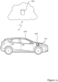
- FIG. 1 illustrates an electric motor (or hybrid) vehicle 100 according to an embodiment.
- the vehicle 100 comprises a battery 110 such as a rechargeable lithium-ion battery which may be charged via a vehicle connector (not shown).
- a vehicle connector not shown
- the method of detecting latent faults of battery cells according to embodiments may be used in other vehicles, such as trucks, boats, aeroplanes, etc.
- An energy storage system may be used in a vehicle travelling by land, sea or air, or in a stationary energy storage application. Further, it may be envisaged that the invention is implemented in other contexts, such as for example in stationary energy storage systems, aerospace applications, such as satellites, space suits and space stations, military applications, etc.
- embodiments are implemented with other types of batteries, such as for instance of any of the following types: solid state, lithium-air, leadacid, nickel-metal hydride, nickel cadmium, etc.
- the vehicle 100 is typically equipped with an Electronic Control Unit (ECU, 120), which may be implemented by one or more microprocessors executing appropriate software for controlling various systems and components in the vehicle.
- ECU Electronic Control Unit
- a car may contain a number of interconnected ECUs for controlling all properties of the car, thereby providing for instance a brake control module (BCM), a speed control module (SCM) or a Battery Management System (BMS).
- BCM brake control module
- SCM speed control module
- BMS Battery Management System
- the ECU 120 may further by equipped with an interface for wireless transmission of data, for instance for wireless communication of various parameters and data and/or measured properties of the vehicle 100 to a remote location.
- FIG. 2 illustrates a battery 110, commonly referred as a battery pack, which comprises a plurality of cells 111:1, ..., 111:n.
- Battery cells 111 are electrochemical units interconnected to form the battery 110.
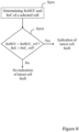
- Figure 3 shows a flow chart illustrating a method according to an embodiment of detecting latent faults in battery cells of a battery such as a rechargeable lithium-ion battery 110 of Figure 2 .
- a potential fault i.e. a latent fault
- a plurality of battery cell properties are taken into account.
- SoH State of Health
- OCV Open Circuit Voltage
- These properties may be measured and updated frequently, such as many times per second.
- the SoH property may be determined by monitoring State of Health Cell Capacity (SoHCC) of a selected cell, which typically is defined as measured or computed amount of electric charge that the cell can deliver at rated voltage.
- SoHCC State of Health Cell Capacity
- the method of detecting a fault in one or more of the battery cells 111:1, ..., 111:n of the battery 110 comprises determining SoHCC and OCV of a selected battery cell and comparing a value of the monitored SoHCC and a value of the determined OCV with a reference value for the SoHCC and a reference value the OCV, wherein the selected battery cell is detected as being faulty if a determined value of the SoHCC of the selected cell is lower than the reference value for the SoHCC while a determined value of the OCV of the selected battery cell is higher than the reference value for the OCV.
- the ECU 120 acquires information indicating the OCV and the SoHCC of a selected cell, for instance first cell 111:1, for example by performing an actual measurement on the selected cell 111:1, or by receiving the information from the battery 110. Either way, the acquired information representing at least one determined value of each of the OCV and the SoHCC is compared to a reference value for the OCV (OCV_ref) and a reference value for the SoHCC (SoHCC_ref) in step S102.
- OCV_ref a reference value for the OCV
- SoHCC_ref SoHCC_ref
- This information is typically managed and monitored by the BMS provided by the ECU 120.
- the OCV and the SoHCC may be continuously monitored and compared to the corresponding reference value, which reference values may change over time.
- the ECU 120 will conclude that there may be a latent fault in the selected battery cell. Hence, an indication of a latent fault may be detected.
- the method is exemplified for a single cell, while in practice all cells may be continuously monitored.
- the ECU 120 By determining whether or not the monitored OCV is higher than the OCV reference value and the monitored SoHCC is lower than the SoHCC reference value, the ECU 120 is capable of detecting a latent fault of the cell, since the high OCV value and the low SoHCC value indicates that there may be something faulty with the cell. Hence, the high OCV value and the low SoHCC value give the cell a signature, which typically deviates from that of the remining cells in the battery 110.
- the reference values for the battery cell properties OCV and SoHCC may be attained and selected in a number of different ways.
- the ECU 120 continuously monitors these properties for each cell and compares the monitored values of the OCV and the SoHCC of each cell to predetermined (not necessarily fixed) reference values OCV_ref and SoHCC_ref in order to determine if one or more cells appear to be faulty.
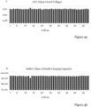
- FIGs 4a and 4b illustrate a practical example of values of the monitored properties OCV and SoHCC.
- a battery comprising 48 cells is monitored and as is illustrated cell no. 13 appears to be impaired with a latent fault.
- the refence values are set such that in a scenario where for a given battery cell (e.g. cell no. 13) the monitored OCV > 3,520 V, and the monitored SoHCC ⁇ 94,9%, the ECU 120 may be conclude that cell no. 13 contains a latent fault.
- the ECU 120 may signal to a driver via a display of the vehicle 100, or even to a remote system and/or operator, that battery service is required, or to have the BMS e.g. to limit the current allowed to flow to and/or from the cell until the battery 110 can be serviced, and even disconnect cell no. 13 which is indicated to contain a latent fault from the remaining cells.
- the ECU 120 determines a signature of a battery cell by concluding whether the monitored value of the OCV is higher than the set OCV reference value while the monitored value of the SoHCC is lower than the set SoHCC reference value.
- SoC State of Charge
- the SoC indicates charging level of a cell and may be based on OCV and historical data such as electrical current that has flowed in and out of the cell. SoC is a computed value and is updated slower than OCV.
- Figure 5 shows a flow chart illustrating a method of detecting latent faults in battery cells of a battery according to this further embodiment.
- a first step S201 the ECU 120 acquires information indicating the OCV, the SoHCC and the SoC of a selected cell, for example by performing an actual measurement on the selected cell, or by receiving information from the battery 110. Either way, the acquired information representing at least one determined value of each of the OCV, the SoHCC and the SoC is compared respectively to a reference value for the OCV (OCV_ref), the SoHCC (SoHCC_ref), and the SoC (SoC_ref) in step S202.
- OCV_ref OCV
- SoHCC_ref SoHCC_ref
- SoC_ref SoC_ref
- the OCV, the SoHCC and the SoC may be continuously monitored by the ECU 120 and compared to the corresponding reference value, which reference values may change over time.
- the ECU 120 may conclude that there is a latent fault in the selected battery cell.
- the accuracy in the detection increases as deviation in a further property is required for a cell to be considered to be impaired with a latent fault.
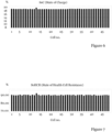
- Figure 6 illustrates a practical example of values of the monitored property SoC. Again, a battery comprising 48 cells is monitored and as is illustrated cell no. 13 appears to be impaired with a latent fault.
- the refence values are set such that in a scenario where for a given battery cell (e.g. cell no. 13) the monitored OCV > 3,520 V, the monitored SoHCC ⁇ 94,9 % and the monitored SoC > 18.9 % , the ECU 120 will conclude that cell no. 13 may contain a latent fault.
- SoHCR State of Health Cell Resistance
- the accuracy in the detection increases even further as deviation in yet a further property is required for a cell to be considered to be impaired with a latent fault.
- Figure 7 illustrates a practical example of values of the monitored property SoHCR.
- a battery comprising 48 cells is monitored and as is illustrated cell no. 13 appears to be impaired with a latent fault.
- SoHCR_ref the reference value for SoHCR
- the monitored SoHCR must be above 89.6 % for a cell to be considered to have a latent fault (in addition to the OCV and the SoC being higher than their respective reference values, and the SoHCC being lower than its reference value).
- Figure 8 shows a flow chart illustrating a method according to an embodiment of detecting latent faults in battery cells of a battery by monitoring SOC and SoHCC.
- a first step S301 the ECU 120 acquires information indicating the SoHCC and the SoC of a selected cell, for example by performing an actual measurement on the selected cell, or by receiving the information from the battery 110. Either way, the acquired information representing at least one monitored value of the SoHCC and the SoC is compared to SoHCC_ref and SoC_ref in step S302.
- the ECU 120 may conclude that there is a latent fault in the selected battery cell.
- the reference values are set such that in a scenario where for a given battery cell (e.g. cell no. 13) the monitored SoHCC ⁇ 94,9 % and the monitored SoC > 18.9 % , the ECU 120 concludes that cell no. 13 may contain a latent fault.
- Figure 9 shows a flow chart illustrating a method according to an embodiment of detecting latent faults in battery cells of a battery by determining OCV and SoHCR.
- a first step S401 the ECU 120 acquires information indicating the OCV and the SoHCR of a selected cell, for example by performing an actual measurement on the selected cell, or by receiving the information from the battery 110. Either way, the acquired information representing at least one monitored value of the OCV and the SoHCR is compared to OCV_ref and SoHCR_ref in step S402.
- the ECU 120 will conclude that there may be a latent fault in the selected battery cell.
- the refence values are set such that in a scenario where for a given battery cell (e.g. cell no. 13) the monitored OCV > 3.520 V and the monitored SoHCR > 89.6 % , the ECU 120 will conclude that cell no. 13 may contain a latent fault.
- Figure 10 shows a flow chart illustrating a method according to an embodiment of detecting latent faults in battery cells of a battery by considering SoC and SoHCR.
- a first step S501 the ECU 120 acquires information indicating the SoC and the SoHCR of a selected cell, for example by performing an actual measurement on the selected cell, or by receiving the information from the battery 110. Either way, the acquired information representing at least one determined value of the SoC and the SoHCR is compared to SoC_ref and SoHCR_ref in step S502.
- the ECU 120 will conclude that there may be a latent fault in the selected battery cell.
- the refence values are set such that in a scenario where for a given battery cell (e.g. cell no. 13) the monitored SoC > 18.9 % and the monitored SoHCR > 89.6 % , the ECU 120 will conclude that cell no. 13 may contain a latent fault.
- the reference values may differ from one battery to another and may thus be individually set for a particular battery. Further it may be envisaged that environmental properties, such as ambient temperature, may affect the setting of the refence values.
- the determined OCV, SoC and SoHCR for a specific cell and the determined value of the SoHCC should be higher and lower respectively with some margin for the deviating cell to be considered faulty. This is to ensure that the detected deviation is considered to be significant enough to give high confidence in the detection.
- the determined OCV, SoC, SOHCC and SoHCR of each cell is compared to a mean or median value of the battery's OCV, SoC, SOHCC and SoHCR respectively, for the remaining cells (the respective mean or median value possibly including the determined values of the selected cell).
- OCV, SoC, SoHCC and SoHCR of a selected cell is monitored over a time period, e.g. over multiple seconds/minutes/hours/days, to ensure that the monitored values consistently deviate from the reference values, and that the monitored values are not just temporary outliers. This may ensure that the signature is indeed established and may further avoid misdetection. This may also allow the BMS to follow the cell data trend and recognize whether or not the latent fault is progressing.
- Figures 4a, 4b , 6 and 7 illustrate a practical example of the monitored properties.
- the OCV of each of the 48 cells is monitored.
- the OCV of cell no. 13 is 3,524 V while the mean and median OCV of all 48 cells is 3,520 V. 3,520 V is used as the reference value in this example.
- Cell no. 13 has a monitored OCV being higher than OCV_ref, with some margin.
- the SoHCC of each of the 48 cells is monitored.
- the SoHCC of cell no. 13 is 91,34% while the mean SoHCC is 94,82% and the median SoHCC is 94,95%. 94,9% is used as the reference value in this example.
- Cell no. 13 has a monitored SoHCC being lower than SoHCC_ref, with some margin.
- the SoC of each of the 48 cells is monitored.
- the SoC of cell no. 13 is 19,56% while the mean SoC is 18,87 and the median SoC is 18,86%. 18,9% is used as the reference value in this example.
- Cell no. 13 has a monitored SoC being higher than SoC_ref, with some margin.
- the SoHCR of each of the 48 cells is monitored.
- the SoHCR of cell no. 13 is 91,79% while the mean SoHCR is 89,58% and the median SoHCR is 89,62%. 89,6% is used as the reference value in this example.
- Cell no. 13 therefore has a monitored SoHCR being higher than SoHCR_ref, with some margin.
- Figure 10 illustrates a further embodiment where the determination as to whether a battery cell of the battery 110 suffers from a latent fault or not is performed remote from the vehicle 100 itself, in this example at a server 130 of for instance a car manufacturer or a car pool operator.
- the ECU 120 may wirelessly communicate determined values of SoHCC, SoHCR, SoC, and OCV of one or more selected battery cells, and any appropriately selected reference values for each of the SoHCC, the SoHCR, the SoC and the OCV, to the server 130 which determines from the received data whether one or more cells are faulty or not.
- the ECU 120 may perform the actual detection and communicate the result to the server 130.
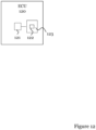
- FIG 11 illustrates an ECU 120 included in the vehicle 100 according to an embodiment.
- the steps of the method of detecting at least one faulty battery cell among a plurality of battery cells in a battery are in practice performed by a processing unit 121 embodied in the form of one or more microprocessors arranged to execute a computer program 122 downloaded to a suitable storage volatile medium 123 associated with the microprocessor, such as a Random Access Memory (RAM), or a non-volatile storage medium such as a Flash memory or a hard disk drive.
- the processing unit 121 is arranged to cause the ECU 120 to carry out the method according to embodiments when the appropriate computer program 122 comprising computer-executable instructions is downloaded to the storage medium 123 and executed by the processing unit 121.
- the storage medium 123 may also be a computer program product comprising the computer program 122.
- the computer program 122 may be transferred to the storage medium 123 by means of a suitable computer program product, such as a Digital Versatile Disc (DVD) or a memory stick.
- DVD Digital Versatile Disc
- the computer program 122 may be downloaded to the storage medium 123 over a network.
- the processing unit 121 may alternatively be embodied in the form of a digital signal processor (DSP), an application specific integrated circuit (ASIC), a field-programmable gate array (FPGA), a complex programmable logic device (CPLD), etc.
Description
- The present disclosure relates to a method of detecting a latent fault of at least one cell among a plurality of cells in an energy storage system, and a control unit performing the method.
- In an energy storage system, such as a battery, for instance a rechargeable lithium-ion battery used in an electric car, cell faults may occur.
- Prior art methods used for detecting faulty cells based on identifying one or more cells having a lower Open Circuit Voltage (OCV) and/or State of Charge (SoC) compared to remaining cells. These methods are effective in identifying cells that already are faulty.
- Preferably, a latent fault of a cell should be detected before it actually develops into an active fault, possibly causing Spontaneous Internal Short Circuits (SISC) which can lead to thermal events such as fire.
- Hence, detecting latent faults within battery cells may be crucial in an energy storage system.
-
US 2016/0327613 discloses battery state estimating device comprising a first estimating part that estimates internal resistance of a secondary battery at predetermined timing; a first calculating part that calculates a first ratio of the internal resistance of the secondary battery in an initial state to the internal resistance of the secondary battery at the predetermined timing; a storage that stores associated data that associates an internal resistance ratio which is a ratio of the internal resistance of the secondary battery in the initial state to the internal resistance of the secondary battery in a degraded state with a full charge capacity ratio which is a ratio of a full charge capacity of the secondary battery in the initial state to the full charge capacity of the secondary battery in the degraded state; and a second estimating part that estimates the full charge capacity of the secondary battery at the predetermined timing based on the first ratio calculated by the first calculating part with reference to the associated data. - An objective is to provide a method of detecting latent faults in cells of an energy storage system. This object is achieved by a method according to
claims claims claims 12 and 13. - If a determined OCV for a selected cell is higher than an OCV reference value for the cell and a determined State of Health Cell Capacity (SoHCC) for the selected cell is lower than an SoHCC reference value for the cell, it is concluded that there may be a latent fault in the selected cell. By determining whether or not the determined OCV is higher than the OCV reference value and the determined SoHCC is lower than the SoHCC reference value, a latent fault of the cell (or at least an indication of a latent fault) can be detected, since the high OCV value and the low SoHCC value indicates that there is something faulty with the cell. Hence, the high OCV value and the low SoHCC value give the cell a signature, which typically deviates from that of the remining cells in the energy storage system.
- Generally, all terms used in the claims are to be interpreted according to their ordinary meaning in the technical field, unless explicitly defined otherwise herein. All references to "a/an/the element, apparatus, component, means, step, etc." are to be interpreted openly as referring to at least one instance of the element, apparatus, component, means, step, etc., unless explicitly stated otherwise. The steps of any method disclosed herein do not have to be performed in the exact order disclosed, unless explicitly stated.
- Aspects and embodiments are now described, by way of example, with reference to the accompanying drawings, in which:
-
Figure 1 illustrates an electric/hybrid motor vehicle in which embodiments may be implemented; -
Figure 2 illustrates an energy storage system in the form of a battery comprising a plurality of cells; -
Figure 3 shows a flow chart illustrating a method of detecting latent faults in battery cells of a battery according to an embodiment; -
Figure 4a illustrates a practical example of a first monitored property of cells in a battery; -
Figure 4b illustrates a practical example of a second monitored property of cells in a battery; -
Figure 5 shows a flow chart illustrating a method of detecting latent faults in battery cells of a battery according to a further embodiment; -
Figure 6 illustrates a practical example of a third monitored property of cells in a battery; -
Figure 7 illustrates a practical example of a fourth monitored property of cells in a battery; -
Figure 8 shows a flow chart illustrating a method of detecting latent faults in battery cells of a battery according to a further embodiment; -
Figure 9 shows a flow chart illustrating a method of detecting latent faults in battery cells of a battery according to a further embodiment; -
Figure 10 shows a flow chart illustrating a method of detecting latent faults in battery cells of a battery according to a further embodiment; -
Figure 11 illustrates wireless communication of data to a remote location according to an embodiment); and -
Figure 12 illustrates an ECU according to an embodiment. - The aspects of the present disclosure will now be described more fully hereinafter with reference to the accompanying drawings, in which certain embodiments of the invention are shown.
- These aspects may, however, be embodied in many different forms and should not be construed as limiting; rather, these embodiments are provided by way of example so that this disclosure will be thorough and complete, and to fully convey the scope of all aspects of invention to those skilled in the art. Like numbers refer to like elements throughout the description.
-
Figure 1 illustrates an electric motor (or hybrid)vehicle 100 according to an embodiment. Thevehicle 100 comprises abattery 110 such as a rechargeable lithium-ion battery which may be charged via a vehicle connector (not shown). It is noted that the car too illustrated inFigure 1 is used as an example only. The method of detecting latent faults of battery cells according to embodiments may be used in other vehicles, such as trucks, boats, aeroplanes, etc. An energy storage system may be used in a vehicle travelling by land, sea or air, or in a stationary energy storage application. Further, it may be envisaged that the invention is implemented in other contexts, such as for example in stationary energy storage systems, aerospace applications, such as satellites, space suits and space stations, military applications, etc. - It is further envisaged that embodiments are implemented with other types of batteries, such as for instance of any of the following types: solid state, lithium-air, leadacid, nickel-metal hydride, nickel cadmium, etc.
- The
vehicle 100, or thebattery 110 itself, is typically equipped with an Electronic Control Unit (ECU, 120), which may be implemented by one or more microprocessors executing appropriate software for controlling various systems and components in the vehicle. A car may contain a number of interconnected ECUs for controlling all properties of the car, thereby providing for instance a brake control module (BCM), a speed control module (SCM) or a Battery Management System (BMS). The ECU 120 may further by equipped with an interface for wireless transmission of data, for instance for wireless communication of various parameters and data and/or measured properties of thevehicle 100 to a remote location. -
Figure 2 illustrates abattery 110, commonly referred as a battery pack, which comprises a plurality of cells 111:1, ..., 111:n.Battery cells 111 are electrochemical units interconnected to form thebattery 110. - As previously discussed, it is desirable to detect latent faults in one or
more battery cells 111 of thebattery 110, since such faults for instance may lead to Spontaneous Internal Short Circuits (SISC) and thermal events potentially causing damages. -
Figure 3 shows a flow chart illustrating a method according to an embodiment of detecting latent faults in battery cells of a battery such as a rechargeable lithium-ion battery 110 ofFigure 2 . - Now, in order to detect a potential fault, i.e. a latent fault, in one or more of the
battery cells 111, a plurality of battery cell properties are taken into account. - A property of a selected cell referred to as State of Health (SoH) is considered. The SoH indicates condition of a cell and is typically graded from 0 to 100% where a full 100% indicates that the conditions of a battery cell match those of the specifications.
- Further, a property of the selected cell referred to as Open Circuit Voltage (OCV) is considered. The OCV simply indicates the voltage difference between the two terminals of each battery cell.
- These properties may be measured and updated frequently, such as many times per second.
- The SoH property may be determined by monitoring State of Health Cell Capacity (SoHCC) of a selected cell, which typically is defined as measured or computed amount of electric charge that the cell can deliver at rated voltage.
- The method of detecting a fault in one or more of the battery cells 111:1, ..., 111:n of the
battery 110 according to an embodiment comprises determining SoHCC and OCV of a selected battery cell and comparing a value of the monitored SoHCC and a value of the determined OCV with a reference value for the SoHCC and a reference value the OCV, wherein the selected battery cell is detected as being faulty if a determined value of the SoHCC of the selected cell is lower than the reference value for the SoHCC while a determined value of the OCV of the selected battery cell is higher than the reference value for the OCV. - Hence, in a first step S101, the
ECU 120 acquires information indicating the OCV and the SoHCC of a selected cell, for instance first cell 111:1, for example by performing an actual measurement on the selected cell 111:1, or by receiving the information from thebattery 110. Either way, the acquired information representing at least one determined value of each of the OCV and the SoHCC is compared to a reference value for the OCV (OCV_ref) and a reference value for the SoHCC (SoHCC_ref) in step S102. - This information is typically managed and monitored by the BMS provided by the
ECU 120. The OCV and the SoHCC may be continuously monitored and compared to the corresponding reference value, which reference values may change over time. - As is shown, if the monitored OCV is higher than OCV_ref and the monitored SoHCC is lower than SoHCC_ref in step S102, the
ECU 120 will conclude that there may be a latent fault in the selected battery cell. Hence, an indication of a latent fault may be detected. As is understood, for brevity the method is exemplified for a single cell, while in practice all cells may be continuously monitored. - By determining whether or not the monitored OCV is higher than the OCV reference value and the monitored SoHCC is lower than the SoHCC reference value, the
ECU 120 is capable of detecting a latent fault of the cell, since the high OCV value and the low SoHCC value indicates that there may be something faulty with the cell. Hence, the high OCV value and the low SoHCC value give the cell a signature, which typically deviates from that of the remining cells in thebattery 110. - The reference values for the battery cell properties OCV and SoHCC may be attained and selected in a number of different ways.
- In an embodiment, it is envisaged that the
ECU 120 continuously monitors these properties for each cell and compares the monitored values of the OCV and the SoHCC of each cell to predetermined (not necessarily fixed) reference values OCV_ref and SoHCC_ref in order to determine if one or more cells appear to be faulty. -
Figures 4a and 4b illustrate a practical example of values of the monitored properties OCV and SoHCC. InFigures 4a and b , a battery comprising 48 cells is monitored and as is illustrated cell no. 13 appears to be impaired with a latent fault. - For instance, in a numerical example OCV_ref = 3,520 V and SoHCC_ref = 94,9 %. Thus, the refence values are set such that in a scenario where for a given battery cell (e.g. cell no. 13) the monitored OCV > 3,520 V, and the monitored SoHCC < 94,9%, the
ECU 120 may be conclude that cell no. 13 contains a latent fault. - As a consequence, the
ECU 120 may signal to a driver via a display of thevehicle 100, or even to a remote system and/or operator, that battery service is required, or to have the BMS e.g. to limit the current allowed to flow to and/or from the cell until thebattery 110 can be serviced, and even disconnect cell no. 13 which is indicated to contain a latent fault from the remaining cells. - With this embodiment, the
ECU 120 determines a signature of a battery cell by concluding whether the monitored value of the OCV is higher than the set OCV reference value while the monitored value of the SoHCC is lower than the set SoHCC reference value. - In a further embodiment, a cell property referred to as State of Charge (SoC) is considered. The SoC indicates charging level of a cell and may be based on OCV and historical data such as electrical current that has flowed in and out of the cell. SoC is a computed value and is updated slower than OCV.
-
Figure 5 shows a flow chart illustrating a method of detecting latent faults in battery cells of a battery according to this further embodiment. - In a first step S201, the
ECU 120 acquires information indicating the OCV, the SoHCC and the SoC of a selected cell, for example by performing an actual measurement on the selected cell, or by receiving information from thebattery 110. Either way, the acquired information representing at least one determined value of each of the OCV, the SoHCC and the SoC is compared respectively to a reference value for the OCV (OCV_ref), the SoHCC (SoHCC_ref), and the SoC (SoC_ref) in step S202. - Again, the OCV, the SoHCC and the SoC may be continuously monitored by the
ECU 120 and compared to the corresponding reference value, which reference values may change over time. - As is shown, if the monitored OCV is higher than OCV_ref, the monitored SoHCC is lower than SoHCC_ref, and the monitored SoC is higher than SoC_ref in step S102, the
ECU 120 may conclude that there is a latent fault in the selected battery cell. - By further taking into account the SoC property in the detection of latent faults, the accuracy in the detection increases as deviation in a further property is required for a cell to be considered to be impaired with a latent fault.
-
Figure 6 illustrates a practical example of values of the monitored property SoC. Again, a battery comprising 48 cells is monitored and as is illustrated cell no. 13 appears to be impaired with a latent fault. - For instance, in a numerical example OCV_ref = 3,520 V and SoHCC_ref = 94,9 % (cf.
Figures 4a and b ), while SoC_ref = 18.9 %. Thus, the refence values are set such that in a scenario where for a given battery cell (e.g. cell no. 13) the monitored OCV > 3,520 V, the monitored SoHCC < 94,9 % and the monitored SoC > 18.9 % , theECU 120 will conclude that cell no. 13 may contain a latent fault. - In another embodiment, a further cell property referred to as State of Health Cell Resistance (SoHCR) is considered, which typically is defined as measured or computed internal impedance of the cell.
- By further taking into account the SoHCR property in the detection of latent faults, the accuracy in the detection increases even further as deviation in yet a further property is required for a cell to be considered to be impaired with a latent fault.
-
Figure 7 illustrates a practical example of values of the monitored property SoHCR. Again, a battery comprising 48 cells is monitored and as is illustrated cell no. 13 appears to be impaired with a latent fault. Assuming for instance that the reference value for SoHCR (SoHCR_ref) is set to 89.6 %, then the monitored SoHCR must be above 89.6 % for a cell to be considered to have a latent fault (in addition to the OCV and the SoC being higher than their respective reference values, and the SoHCC being lower than its reference value). - In another aspect, in order to detect a latent fault in one or more of the battery cells of the
battery 110, only the properties SOC and SoHCC are monitored. -
Figure 8 shows a flow chart illustrating a method according to an embodiment of detecting latent faults in battery cells of a battery by monitoring SOC and SoHCC. - In a first step S301, the
ECU 120 acquires information indicating the SoHCC and the SoC of a selected cell, for example by performing an actual measurement on the selected cell, or by receiving the information from thebattery 110. Either way, the acquired information representing at least one monitored value of the SoHCC and the SoC is compared to SoHCC_ref and SoC_ref in step S302. - As is shown, if the monitored SoHCC is lower than SoHCC_ref, and the monitored SoC is higher than SoC_ref in step S302, the
ECU 120 may conclude that there is a latent fault in the selected battery cell. As previously shown inFigures 4b and6 , SoHCC_ref = 94,9 % while SoC_ref = 18.9 %. Thus, the reference values are set such that in a scenario where for a given battery cell (e.g. cell no. 13) the monitored SoHCC < 94,9 % and the monitored SoC > 18.9 % , theECU 120 concludes that cell no. 13 may contain a latent fault. - In yet another aspect, in order to detect a latent fault in one or more of the battery cells of the
battery 110, only the properties OCV and SoHCR are considered. -
Figure 9 shows a flow chart illustrating a method according to an embodiment of detecting latent faults in battery cells of a battery by determining OCV and SoHCR. - In a first step S401, the
ECU 120 acquires information indicating the OCV and the SoHCR of a selected cell, for example by performing an actual measurement on the selected cell, or by receiving the information from thebattery 110. Either way, the acquired information representing at least one monitored value of the OCV and the SoHCR is compared to OCV_ref and SoHCR_ref in step S402. - As is shown, if the monitored OCV is higher than OCV_ref, and the monitored SoHCR is higher than SoHCR_ref in step S402, the
ECU 120 will conclude that there may be a latent fault in the selected battery cell. As previously shown inFigures 4a and7 , OCV_ref = 3,520 V while SoHCR_ref = 89.6 %. Thus, the refence values are set such that in a scenario where for a given battery cell (e.g. cell no. 13) the monitored OCV > 3.520 V and the monitored SoHCR > 89.6 % , theECU 120 will conclude that cell no. 13 may contain a latent fault. - In still another aspect, in order to detect a latent fault in one or more of the battery cells of the
battery 110, only the properties SoC and SoHCR are monitored. -
Figure 10 shows a flow chart illustrating a method according to an embodiment of detecting latent faults in battery cells of a battery by considering SoC and SoHCR. - In a first step S501, the
ECU 120 acquires information indicating the SoC and the SoHCR of a selected cell, for example by performing an actual measurement on the selected cell, or by receiving the information from thebattery 110. Either way, the acquired information representing at least one determined value of the SoC and the SoHCR is compared to SoC_ref and SoHCR_ref in step S502. - As is shown, if the monitored SoC is higher than SoC_ref, and the monitored SoHCR is higher than SoHCR_ref in step S502, the
ECU 120 will conclude that there may be a latent fault in the selected battery cell. As previously shown inFigures 6 and 7 , SoC_ref = 18.9 % while SoHCR_ref = 89.6 %. Thus, the refence values are set such that in a scenario where for a given battery cell (e.g. cell no. 13) the monitored SoC > 18.9 % and the monitored SoHCR > 89.6 % , theECU 120 will conclude that cell no. 13 may contain a latent fault. - It is understood that the reference values may differ from one battery to another and may thus be individually set for a particular battery. Further it may be envisaged that environmental properties, such as ambient temperature, may affect the setting of the refence values.
- In an embodiment, it is envisaged that the determined OCV, SoC and SoHCR for a specific cell and the determined value of the SoHCC should be higher and lower respectively with some margin for the deviating cell to be considered faulty. This is to ensure that the detected deviation is considered to be significant enough to give high confidence in the detection.
- It may further be envisaged that the determined OCV, SoC, SOHCC and SoHCR of each cell is compared to a mean or median value of the battery's OCV, SoC, SOHCC and SoHCR respectively, for the remaining cells (the respective mean or median value possibly including the determined values of the selected cell).
- In a further embodiment, OCV, SoC, SoHCC and SoHCR of a selected cell is monitored over a time period, e.g. over multiple seconds/minutes/hours/days, to ensure that the monitored values consistently deviate from the reference values, and that the monitored values are not just temporary outliers. This may ensure that the signature is indeed established and may further avoid misdetection. This may also allow the BMS to follow the cell data trend and recognize whether or not the latent fault is progressing.
- As previously discussed,
Figures 4a, 4b ,6 and 7 illustrate a practical example of the monitored properties. - In
Figure 4a , the OCV of each of the 48 cells is monitored. The OCV of cell no. 13 is 3,524 V while the mean and median OCV of all 48 cells is 3,520 V. 3,520 V is used as the reference value in this example. Cell no. 13 has a monitored OCV being higher than OCV_ref, with some margin. - In
Figure 4b , the SoHCC of each of the 48 cells is monitored. The SoHCC of cell no. 13 is 91,34% while the mean SoHCC is 94,82% and the median SoHCC is 94,95%. 94,9% is used as the reference value in this example. Cell no. 13 has a monitored SoHCC being lower than SoHCC_ref, with some margin. - In
Figure 6 , the SoC of each of the 48 cells is monitored. The SoC of cell no. 13 is 19,56% while the mean SoC is 18,87 and the median SoC is 18,86%. 18,9% is used as the reference value in this example. Cell no. 13 has a monitored SoC being higher than SoC_ref, with some margin. - Finally, in
Figure 7 , the SoHCR of each of the 48 cells is monitored. The SoHCR of cell no. 13 is 91,79% while the mean SoHCR is 89,58% and the median SoHCR is 89,62%. 89,6% is used as the reference value in this example. Cell no. 13 therefore has a monitored SoHCR being higher than SoHCR_ref, with some margin. -
Figure 10 illustrates a further embodiment where the determination as to whether a battery cell of thebattery 110 suffers from a latent fault or not is performed remote from thevehicle 100 itself, in this example at aserver 130 of for instance a car manufacturer or a car pool operator. Hence, theECU 120 may wirelessly communicate determined values of SoHCC, SoHCR, SoC, and OCV of one or more selected battery cells, and any appropriately selected reference values for each of the SoHCC, the SoHCR, the SoC and the OCV, to theserver 130 which determines from the received data whether one or more cells are faulty or not. Alternatively, theECU 120 may perform the actual detection and communicate the result to theserver 130. -
Figure 11 illustrates anECU 120 included in thevehicle 100 according to an embodiment. The steps of the method of detecting at least one faulty battery cell among a plurality of battery cells in a battery are in practice performed by aprocessing unit 121 embodied in the form of one or more microprocessors arranged to execute acomputer program 122 downloaded to a suitable storagevolatile medium 123 associated with the microprocessor, such as a Random Access Memory (RAM), or a non-volatile storage medium such as a Flash memory or a hard disk drive. Theprocessing unit 121 is arranged to cause theECU 120 to carry out the method according to embodiments when theappropriate computer program 122 comprising computer-executable instructions is downloaded to thestorage medium 123 and executed by theprocessing unit 121. Thestorage medium 123 may also be a computer program product comprising thecomputer program 122. Alternatively, thecomputer program 122 may be transferred to thestorage medium 123 by means of a suitable computer program product, such as a Digital Versatile Disc (DVD) or a memory stick. As a further alternative, thecomputer program 122 may be downloaded to thestorage medium 123 over a network. Theprocessing unit 121 may alternatively be embodied in the form of a digital signal processor (DSP), an application specific integrated circuit (ASIC), a field-programmable gate array (FPGA), a complex programmable logic device (CPLD), etc. - The aspects of the present disclosure have mainly been described above with reference to a few embodiments and examples thereof. However, as is readily appreciated by a person skilled in the art, other embodiments than the ones disclosed above are equally possible within the scope of the invention, as defined by the appended patent claims.
- Thus, while various aspects and embodiments have been disclosed herein, other aspects and embodiments will be apparent to those skilled in the art. The various aspects and embodiments disclosed herein are for purposes of illustration and are not intended to be limiting, with the true scope being indicated by the following claims.
-
- ASIC - Application Specific Integrated Circuit
- BCM - Brake Control Module
- BMS - Battery Management System
- CPLD - Complex Programmable Logic Device
- DSP - Digital Signal Processor
- DVD - Digital Versatile Disc
- ECU - Electronic Control Unit
- FPGA - Field-Programmable Gate Array
- OCV - Open Circuit Voltage
- RAM - Random Access Memory
- SCM - Speed Control Module
- SISC - Spontaneous Internal Short Circuits
- SoC - State of Charge
- SoH - State of Health
- SoHCC - State of Health Cell Capacity
- SoHCR - State of Health Cell Resistance
Claims (16)
- A method of detecting a latent fault of at least one cell (111:1) among a plurality of cells (111:2-111:n) in an energy storage system (110), comprising:
determining (S101) State of Health Cell Capacity, SoHCC, and Open Circuit Voltage, OCV, of a selected cell; wherein the selected cell is indicated (S102) to have a latent fault if a determined value of the SoHCC of the selected cell is lower than a reference value for the SoHCC and if a determined value of the OCV of the selected cell is higher than a reference value for the OCV. - The method of claim 1, further comprising:
determining (S201) State of Charge, SoC, of the selected cell (111:1); wherein the selected cell is indicated (S202) to have a latent fault if the determined value of the SoC of the selected cell is higher than a reference value for the SoC. - The method of claim 2, further comprising:determining State of Health Cell Resistance, SoHCR, of the selected cell (111:1);wherein the selected cell is indicated to have a latent fault if the determined value of the SoHCR of the selected cell is higher than a reference value for the SoHCR.
- A method of detecting a latent fault of at least one cell (111:1) among a plurality of cells (111:2-111:n) in an energy storage system (110), comprising:
determining (S301) State of Health Cell Capacity, SoHCC, and State of Charge, SoC, of a selected cell; wherein the selected cell is indicated (S302) to have a latent fault if a determined value of the SoHCC of the selected cell is lower than a reference value for the SoHCC and if a determined value of the SoC of the selected cell is higher than a reference value for the SoC. - A method of detecting a latent fault of at least one cell (111:1) among a plurality of cells (111:2-111:n) in an energy storage system (110), comprising:
determining (S401) State of Health Cell Resistance, SoHCR, and Open Circuit Voltage, OCV, of a selected cell; wherein the selected cell is indicated (S402) to have a latent fault if a determined value of the SoHCR of the selected cell is higher than a reference value for the SoHCR and if a determined value of the OCV of the selected cell is higher than a reference value for the OCV. - A method of detecting a latent fault of at least one cell (111:1) among a plurality of cells (111:2-111:n) in an energy storage system (110), comprising:
determining (S501) State of Health Cell Resistance, SoHCR, and State of Charge, SoC, of a selected cell; wherein the selected cell is indicated (S502) to have a latent fault if a determined value of the SoHCR of the selected cell is higher than a reference value for the SoHCR and if a determined value of the SoC of the selected cell is higher than a reference value for the SoC. - The method of any one of the preceding claims, wherein the reference value for at least one of the OCV, the SoC, the SoHCC and SoHCR is based on a determined value of one or more of the remaining battery cells (111:2-111:n) in the battery (110).
- The method of claim 7, wherein the reference value for at least one of the OCV, the SoC, the SoHCC and SoHCR is based on a determined mean or median value of at least two of the remaining battery cells (111:2-111:n) in the battery (110).
- The method of any one of the preceding claims, wherein a cell data trend is followed to conclude whether or not the indicated latent fault is progressing.
- The method of any one of the preceding claims, further comprising:
signalling an operator that battery service is required and/or disconnecting the selected cell (111:1) from the remaining cells (111:2-111:n) based on the detection of a latent fault and/or limiting a current allowed to flow to and/or from the selected cell until the battery (110) has been serviced. - The method of any one of the preceding claims, further comprising:
wirelessly communicating to a remote location (130) that an indication of a latent cell fault has been detected. - A computer program (122) comprising computer-executable instructions for causing a device (120) to perform steps recited in any one of claims 1-11 when the computer-executable instructions are executed on a processing unit (121) included in the device (120).
- A computer program product comprising a computer readable medium (123), the computer readable medium having the computer program (122) according to claim 12 embodied thereon.
- A control unit (120) configured to detect a latent fault of at least one cell (111:1) among a plurality of cells (111:2-111:n) in an energy storage system (110), the control unit (120) comprising a processing unit (121) and a memory (123), said memory containing instructions (122) executable by said processing unit (121), whereby the control unit (120) is operative to:
determine State of Health Cell Capacity, SoHCC, and Open Circuit Voltage, OCV, of a selected cell; wherein the selected cell is indicated to have a latent fault if a determined value of the SoHCC of the selected cell is lower than a reference value for the SoHCC and if a determined value of the OCV of the selected cell is higher than a reference value for the OCV. - A control unit (120) configured to detect a latent fault of at least one cell (111:1) among a plurality of cells (111:2-111:n) in an energy storage system (110), the control unit (120) comprising a processing unit (121) and a memory (123), said memory containing instructions (122) executable by said processing unit (121), whereby the control unit (120) is operative to:
determine State of Health Cell Capacity, SoHCC, and State of Charge, SoC, of a selected cell; wherein the selected cell is indicated to have a latent fault if a determined value of the SoHCC of the selected cell is lower than a reference value for the SoHCC and if a determined value of the SoC of the selected cell is higher than a reference value for the SoC. - A control unit (120) configured to detect a latent fault of at least one cell (111:1) among a plurality of cells (111:2-111:n) in an energy storage system (110), the control unit (120) comprising a processing unit (121) and a memory (123), said memory containing instructions (122) executable by said processing unit (121), whereby the control unit (120) is operative to:
determine State of Health Cell Resistance, SoHCR, and Open Circuit Voltage, OCV, of a selected cell; wherein the selected cell is indicated to have a latent fault if a determined value of the SoHCR of the selected cell is higher than a reference value for the SoHCR and if a determined value of the OCV of the selected cell is higher than a reference value for the OCV.
Priority Applications (4)
| Application Number | Priority Date | Filing Date | Title |
|---|---|---|---|
| EP19179436.1A EP3751299B1 (en) | 2019-06-11 | 2019-06-11 | Detecting latent faults within a cell of an energy storage system |
| CN202010488547.6A CN112068012A (en) | 2019-06-11 | 2020-06-02 | Detecting a latent fault in a cell of an energy storage system |
| US16/894,933 US11209493B2 (en) | 2019-06-11 | 2020-06-08 | Detecting latent faults within a cell of an energy storage system |
| US17/529,833 US11635471B2 (en) | 2019-06-11 | 2021-11-18 | Detecting latent faults within a cell of an energy storage system |
Applications Claiming Priority (1)
| Application Number | Priority Date | Filing Date | Title |
|---|---|---|---|
| EP19179436.1A EP3751299B1 (en) | 2019-06-11 | 2019-06-11 | Detecting latent faults within a cell of an energy storage system |
Publications (2)
| Publication Number | Publication Date |
|---|---|
| EP3751299A1 EP3751299A1 (en) | 2020-12-16 |
| EP3751299B1 true EP3751299B1 (en) | 2023-08-09 |
Family
ID=66821085
Family Applications (1)
| Application Number | Title | Priority Date | Filing Date |
|---|---|---|---|
| EP19179436.1A Active EP3751299B1 (en) | 2019-06-11 | 2019-06-11 | Detecting latent faults within a cell of an energy storage system |
Country Status (3)
| Country | Link |
|---|---|
| US (2) | US11209493B2 (en) |
| EP (1) | EP3751299B1 (en) |
| CN (1) | CN112068012A (en) |
Family Cites Families (43)
| Publication number | Priority date | Publication date | Assignee | Title |
|---|---|---|---|---|
| JPH0946893A (en) * | 1995-07-28 | 1997-02-14 | Honda Motor Co Ltd | Monitoring system and protective device for set battery |
| CN101107538A (en) * | 2004-11-29 | 2008-01-16 | 水吉能公司 | Systems and methods for detecting and indicating fault conditions in electrochemical cells |
| CN101221224B (en) * | 2006-12-22 | 2010-12-15 | 通用汽车环球科技运作公司 | Method and system for monitoring an electrical energy storage device |
| US8200600B2 (en) * | 2007-03-20 | 2012-06-12 | Irobot Corporation | Electronic system condition monitoring and prognostics |
| US9140761B2 (en) * | 2009-12-25 | 2015-09-22 | Toyota Jidosha Kabushiki Kaisha | Battery pack failure detection device |
| FR2955670B1 (en) * | 2010-01-27 | 2012-01-27 | Commissariat Energie Atomique | METHOD FOR DIAGNOSING THE HEALTH CONDITION OF A BATTERY |
| US8598840B2 (en) * | 2010-04-15 | 2013-12-03 | Launchpoint Energy And Power Llc | Fault-tolerant battery management system, circuits and methods |
| US8797043B2 (en) * | 2010-10-04 | 2014-08-05 | Intersil Americas Inc. | System and method for detection of open connections between an integrated circuit and a multi-cell battery pack |
| DE102010062187A1 (en) * | 2010-11-30 | 2012-05-31 | Sb Limotive Company Ltd. | Method for determining the open circuit voltage of a battery, battery with a module for determining the open circuit voltage and a motor vehicle with a corresponding battery |
| CN102652265A (en) * | 2010-12-06 | 2012-08-29 | 科达汽车公司 | Measuring isolated high voltage and detecting isolation breakdown with measures for self-detection of circuit faults |
| US9157968B1 (en) * | 2011-02-22 | 2015-10-13 | Securaplane Technologies, Inc. | System and method for characterizing the health of a rechargeable battery |
| DE102011015977A1 (en) * | 2011-04-04 | 2012-10-04 | Andreas Stihl Ag & Co. Kg | Method for starting up an electronic drive circuit of an electric motor and circuit arrangement for this purpose |
| WO2013032719A2 (en) * | 2011-09-02 | 2013-03-07 | Boston-Power, Inc. | Method for balancing cells in batteries |
| US8796993B2 (en) * | 2011-09-12 | 2014-08-05 | Southwest Electronic Energy Corporation | Historical analysis of battery cells for determining state of health |
| US9244132B2 (en) | 2011-09-12 | 2016-01-26 | Eaglepicher Technologies, Llc | Systems and methods for determining battery state-of-health |
| US9157966B2 (en) * | 2011-11-25 | 2015-10-13 | Honeywell International Inc. | Method and apparatus for online determination of battery state of charge and state of health |
| US9869725B2 (en) | 2012-05-16 | 2018-01-16 | Robert Bosch Gmbh | Battery system and method with capacity estimator |
| DE102014101728B4 (en) * | 2013-02-22 | 2018-06-28 | GM Global Technology Operations LLC (n. d. Ges. d. Staates Delaware) | A method for identifying a fault in a battery cell and battery cell diagnostic system |
| US9467000B2 (en) * | 2013-05-31 | 2016-10-11 | Raytheon Company | Intelligent independent battery management system and method |
| CN103529281B (en) * | 2013-10-24 | 2016-08-31 | 郑鲲鲲 | Voltage detecting circuit, electronic equipment and the automobile of the real-time OBD of a kind of all standing |
| WO2015115044A1 (en) * | 2014-01-29 | 2015-08-06 | パナソニックIpマネジメント株式会社 | Battery state estimating device and power supply device |
| CN106030325B (en) | 2014-02-25 | 2018-12-07 | 三菱电机株式会社 | The SOC estimating device of secondary cell |
| JP6371415B2 (en) * | 2014-05-28 | 2018-08-08 | ボルボトラックコーポレーション | Method for determining the reliability of degradation state parameters |
| DE102014211797A1 (en) * | 2014-06-19 | 2015-12-24 | Lufthansa Technik Ag | System and method for monitoring a nickel-cadmium battery in a passenger aircraft |
| JP6471463B2 (en) * | 2014-11-06 | 2019-02-20 | 日立化成株式会社 | Storage battery state monitoring system, storage battery state monitoring method, and storage battery state monitoring program |
| US9557387B2 (en) * | 2015-02-10 | 2017-01-31 | Lenovo Enterprise Solutions (Singapore) Pte. Ltd. | Testing individual cells within multi-cell battery applications |
| IL239852A (en) * | 2015-07-08 | 2016-12-29 | Algolion Ltd | Lithium-ion battery safety monitoring |
| JP6453200B2 (en) * | 2015-10-28 | 2019-01-16 | 矢崎総業株式会社 | Voltage detector |
| US10236695B2 (en) * | 2015-12-22 | 2019-03-19 | Vito Nv | Connectivity check between cells and wiring control electronics with only one switch |
| CA3007612A1 (en) * | 2015-12-24 | 2017-06-29 | Vito Nv | Method, system and device for balancing individual electric energy storage cells |
| CN105425168A (en) * | 2016-01-08 | 2016-03-23 | 国网浙江宁波市鄞州区供电公司 | Storage battery capacity detection method and apparatus in power supply system |
| CN105527582B (en) * | 2016-02-03 | 2018-11-20 | 惠州市亿能电子有限公司 | A kind of power battery pack fail battery pre-judging method |
| CN109073712B (en) * | 2016-05-13 | 2022-05-17 | 舒马克电器公司 | Battery state detection system and method |
| CN106353685A (en) * | 2016-08-11 | 2017-01-25 | 华霆(合肥)动力技术有限公司 | Battery fault detection method and apparatus |
| CN106443461B (en) * | 2016-09-06 | 2019-06-14 | 华北电力科学研究院有限责任公司 | Battery energy storage system state evaluating method |
| CN109964138B (en) * | 2016-11-25 | 2022-06-21 | 沃尔沃卡车集团 | Method and apparatus for classifying voltage fault conditions in an electrical storage system |
| US10302709B2 (en) | 2016-11-30 | 2019-05-28 | Cadex Electronics Inc. | Battery state-of-health determination using multi-factor normalization |
| CN106707180B (en) * | 2016-12-01 | 2020-09-11 | 深圳市麦澜创新科技有限公司 | Fault detection method for parallel battery pack |
| CN106696712B (en) * | 2016-12-20 | 2019-06-28 | 常州普莱德新能源电池科技有限公司 | Power battery fault detection method, system and electric vehicle |
| DE102016225988A1 (en) * | 2016-12-22 | 2018-06-28 | Robert Bosch Gmbh | Method and system for detecting fault currents in memory cells |
| US10312699B2 (en) | 2017-07-31 | 2019-06-04 | Robert Bosch Gmbh | Method and system for estimating battery open cell voltage, state of charge, and state of health during operation of the battery |
| US20190120908A1 (en) * | 2017-10-25 | 2019-04-25 | Samsung Electronics Co., Ltd. | Apparatus and methods for identifying anomaly(ies) in re-chargeable battery of equipment and connected component(s) |
| CN108445410B (en) * | 2018-04-02 | 2021-02-26 | 国家计算机网络与信息安全管理中心 | Method and device for monitoring running state of storage battery pack |
-
2019
- 2019-06-11 EP EP19179436.1A patent/EP3751299B1/en active Active
-
2020
- 2020-06-02 CN CN202010488547.6A patent/CN112068012A/en active Pending
- 2020-06-08 US US16/894,933 patent/US11209493B2/en active Active
-
2021
- 2021-11-18 US US17/529,833 patent/US11635471B2/en active Active
Also Published As
| Publication number | Publication date |
|---|---|
| US11635471B2 (en) | 2023-04-25 |
| US11209493B2 (en) | 2021-12-28 |
| US20220075002A1 (en) | 2022-03-10 |
| EP3751299A1 (en) | 2020-12-16 |
| CN112068012A (en) | 2020-12-11 |
| US20210055354A1 (en) | 2021-02-25 |
Similar Documents
| Publication | Publication Date | Title |
|---|---|---|
| US9059486B2 (en) | Automatic crash battery discharge method | |
| US8159186B2 (en) | Power source system, power supply control method for the power source system, power supply control program for the power source system, and computer-readable recording medium with the power supply control program recorded thereon | |
| US9472959B2 (en) | Systems and methods for balancing a vehicle battery system | |
| US9327610B2 (en) | Method for automatic energy discharge of a battery pack via internal battery electronics post crash event | |
| US20220055483A1 (en) | First series then parallel battery pack system | |
| US8269462B2 (en) | State monitoring apparatus for assembled battery | |
| US20220144128A1 (en) | System and method for managing vehicle battery | |
| US9688159B2 (en) | Methods, apparatus, and systems for preventing over-temperature battery operation | |
| EP2799894B1 (en) | Monitoring system and vehicle | |
| US11175341B2 (en) | Method and arrangment for classifying a voltage fault condition in an electrical storage system | |
| US7612540B2 (en) | Lithium-ion battery diagnostic and prognostic techniques | |
| CN108333516B (en) | Battery state testing method and system | |
| US9941714B2 (en) | Battery system and motor vehicle with battery system | |
| EP3751299B1 (en) | Detecting latent faults within a cell of an energy storage system | |
| US11186198B2 (en) | Methods and systems for vehicle battery cell failure detection and overcharge protection | |
| US20140152317A1 (en) | Systems and methods to protect against over-discharge in a battery system | |
| KR20130126128A (en) | Method and apparatus for battery resistance estimation, and battery management system using the same | |
| US9211802B2 (en) | Systems and methods for detecting a weak subdivision in a battery system | |
| EP4203235A1 (en) | Power supply management device and operation method thereof | |
| EP3798047A1 (en) | Facilitating battery maintenance | |
| KR20200124032A (en) | System and method for diagnosing battery current sensor | |
| CN112485685A (en) | Power bearing capacity parameter determination method and device and electronic equipment |
Legal Events
| Date | Code | Title | Description |
|---|---|---|---|
| PUAI | Public reference made under article 153(3) epc to a published international application that has entered the european phase |
Free format text: ORIGINAL CODE: 0009012 |
|
| STAA | Information on the status of an ep patent application or granted ep patent |
Free format text: STATUS: THE APPLICATION HAS BEEN PUBLISHED |
|
| AK | Designated contracting states |
Kind code of ref document: A1 Designated state(s): AL AT BE BG CH CY CZ DE DK EE ES FI FR GB GR HR HU IE IS IT LI LT LU LV MC MK MT NL NO PL PT RO RS SE SI SK SM TR |
|
| AX | Request for extension of the european patent |
Extension state: BA ME |
|
| STAA | Information on the status of an ep patent application or granted ep patent |
Free format text: STATUS: REQUEST FOR EXAMINATION WAS MADE |
|
| 17P | Request for examination filed |
Effective date: 20210616 |
|
| RBV | Designated contracting states (corrected) |
Designated state(s): AL AT BE BG CH CY CZ DE DK EE ES FI FR GB GR HR HU IE IS IT LI LT LU LV MC MK MT NL NO PL PT RO RS SE SI SK SM TR |
|
| GRAP | Despatch of communication of intention to grant a patent |
Free format text: ORIGINAL CODE: EPIDOSNIGR1 |
|
| STAA | Information on the status of an ep patent application or granted ep patent |
Free format text: STATUS: GRANT OF PATENT IS INTENDED |
|
| RIC1 | Information provided on ipc code assigned before grant |
Ipc: G01R 31/396 20190101ALI20230210BHEP Ipc: G01R 31/392 20190101ALI20230210BHEP Ipc: G01R 31/389 20190101ALI20230210BHEP Ipc: G01R 31/367 20190101ALI20230210BHEP Ipc: G01R 31/36 20060101AFI20230210BHEP |
|
| INTG | Intention to grant announced |
Effective date: 20230302 |
|
| RIN1 | Information on inventor provided before grant (corrected) |
Inventor name: LEUCHOVIUS, NICKLAS Inventor name: TIDBLAD AHLBERG, ANNIKA Inventor name: WERBERG, LEOPOLD |
|
| GRAS | Grant fee paid |
Free format text: ORIGINAL CODE: EPIDOSNIGR3 |
|
| GRAA | (expected) grant |
Free format text: ORIGINAL CODE: 0009210 |
|
| STAA | Information on the status of an ep patent application or granted ep patent |
Free format text: STATUS: THE PATENT HAS BEEN GRANTED |
|
| AK | Designated contracting states |
Kind code of ref document: B1 Designated state(s): AL AT BE BG CH CY CZ DE DK EE ES FI FR GB GR HR HU IE IS IT LI LT LU LV MC MK MT NL NO PL PT RO RS SE SI SK SM TR |
|
| REG | Reference to a national code |
Ref country code: GB Ref legal event code: FG4D |
|
| REG | Reference to a national code |
Ref country code: CH Ref legal event code: EP |
|
| REG | Reference to a national code |
Ref country code: DE Ref legal event code: R096 Ref document number: 602019034405 Country of ref document: DE |
|
| REG | Reference to a national code |
Ref country code: IE Ref legal event code: FG4D |
|
| P01 | Opt-out of the competence of the unified patent court (upc) registered |
Effective date: 20230828 |
|
| REG | Reference to a national code |
Ref country code: LT Ref legal event code: MG9D |
|
| REG | Reference to a national code |
Ref country code: NL Ref legal event code: MP Effective date: 20230809 |
|
| REG | Reference to a national code |
Ref country code: AT Ref legal event code: MK05 Ref document number: 1598137 Country of ref document: AT Kind code of ref document: T Effective date: 20230809 |
|
| PG25 | Lapsed in a contracting state [announced via postgrant information from national office to epo] |
Ref country code: GR Free format text: LAPSE BECAUSE OF FAILURE TO SUBMIT A TRANSLATION OF THE DESCRIPTION OR TO PAY THE FEE WITHIN THE PRESCRIBED TIME-LIMIT Effective date: 20231110 |
|
| PG25 | Lapsed in a contracting state [announced via postgrant information from national office to epo] |
Ref country code: IS Free format text: LAPSE BECAUSE OF FAILURE TO SUBMIT A TRANSLATION OF THE DESCRIPTION OR TO PAY THE FEE WITHIN THE PRESCRIBED TIME-LIMIT Effective date: 20231209 |
|
| PG25 | Lapsed in a contracting state [announced via postgrant information from national office to epo] |
Ref country code: SE Free format text: LAPSE BECAUSE OF FAILURE TO SUBMIT A TRANSLATION OF THE DESCRIPTION OR TO PAY THE FEE WITHIN THE PRESCRIBED TIME-LIMIT Effective date: 20230809 Ref country code: RS Free format text: LAPSE BECAUSE OF FAILURE TO SUBMIT A TRANSLATION OF THE DESCRIPTION OR TO PAY THE FEE WITHIN THE PRESCRIBED TIME-LIMIT Effective date: 20230809 Ref country code: PT Free format text: LAPSE BECAUSE OF FAILURE TO SUBMIT A TRANSLATION OF THE DESCRIPTION OR TO PAY THE FEE WITHIN THE PRESCRIBED TIME-LIMIT Effective date: 20231211 Ref country code: NO Free format text: LAPSE BECAUSE OF FAILURE TO SUBMIT A TRANSLATION OF THE DESCRIPTION OR TO PAY THE FEE WITHIN THE PRESCRIBED TIME-LIMIT Effective date: 20231109 Ref country code: NL Free format text: LAPSE BECAUSE OF FAILURE TO SUBMIT A TRANSLATION OF THE DESCRIPTION OR TO PAY THE FEE WITHIN THE PRESCRIBED TIME-LIMIT Effective date: 20230809 Ref country code: LV Free format text: LAPSE BECAUSE OF FAILURE TO SUBMIT A TRANSLATION OF THE DESCRIPTION OR TO PAY THE FEE WITHIN THE PRESCRIBED TIME-LIMIT Effective date: 20230809 Ref country code: LT Free format text: LAPSE BECAUSE OF FAILURE TO SUBMIT A TRANSLATION OF THE DESCRIPTION OR TO PAY THE FEE WITHIN THE PRESCRIBED TIME-LIMIT Effective date: 20230809 Ref country code: IS Free format text: LAPSE BECAUSE OF FAILURE TO SUBMIT A TRANSLATION OF THE DESCRIPTION OR TO PAY THE FEE WITHIN THE PRESCRIBED TIME-LIMIT Effective date: 20231209 Ref country code: HR Free format text: LAPSE BECAUSE OF FAILURE TO SUBMIT A TRANSLATION OF THE DESCRIPTION OR TO PAY THE FEE WITHIN THE PRESCRIBED TIME-LIMIT Effective date: 20230809 Ref country code: GR Free format text: LAPSE BECAUSE OF FAILURE TO SUBMIT A TRANSLATION OF THE DESCRIPTION OR TO PAY THE FEE WITHIN THE PRESCRIBED TIME-LIMIT Effective date: 20231110 Ref country code: FI Free format text: LAPSE BECAUSE OF FAILURE TO SUBMIT A TRANSLATION OF THE DESCRIPTION OR TO PAY THE FEE WITHIN THE PRESCRIBED TIME-LIMIT Effective date: 20230809 Ref country code: AT Free format text: LAPSE BECAUSE OF FAILURE TO SUBMIT A TRANSLATION OF THE DESCRIPTION OR TO PAY THE FEE WITHIN THE PRESCRIBED TIME-LIMIT Effective date: 20230809 |
|
| PG25 | Lapsed in a contracting state [announced via postgrant information from national office to epo] |
Ref country code: PL Free format text: LAPSE BECAUSE OF FAILURE TO SUBMIT A TRANSLATION OF THE DESCRIPTION OR TO PAY THE FEE WITHIN THE PRESCRIBED TIME-LIMIT Effective date: 20230809 |