EP3394558B1 - Umkehrbares sicherheits- und bewehrungssystem für eine explosive vorrichtung - Google Patents
Umkehrbares sicherheits- und bewehrungssystem für eine explosive vorrichtung Download PDFInfo
- Publication number
- EP3394558B1 EP3394558B1 EP16825801.0A EP16825801A EP3394558B1 EP 3394558 B1 EP3394558 B1 EP 3394558B1 EP 16825801 A EP16825801 A EP 16825801A EP 3394558 B1 EP3394558 B1 EP 3394558B1
- Authority
- EP
- European Patent Office
- Prior art keywords
- flap
- pinion
- safety
- rotor
- motor
- Prior art date
- Legal status (The legal status is an assumption and is not a legal conclusion. Google has not performed a legal analysis and makes no representation as to the accuracy of the status listed.)
- Active
Links
Images



Classifications
-
- F—MECHANICAL ENGINEERING; LIGHTING; HEATING; WEAPONS; BLASTING
- F42—AMMUNITION; BLASTING
- F42C—AMMUNITION FUZES; ARMING OR SAFETY MEANS THEREFOR
- F42C15/00—Arming-means in fuzes; Safety means for preventing premature detonation of fuzes or charges
- F42C15/44—Arrangements for disarming, or for rendering harmless, fuzes after arming, e.g. after launch
-
- F—MECHANICAL ENGINEERING; LIGHTING; HEATING; WEAPONS; BLASTING
- F42—AMMUNITION; BLASTING
- F42C—AMMUNITION FUZES; ARMING OR SAFETY MEANS THEREFOR
- F42C15/00—Arming-means in fuzes; Safety means for preventing premature detonation of fuzes or charges
- F42C15/34—Arming-means in fuzes; Safety means for preventing premature detonation of fuzes or charges wherein the safety or arming action is effected by a blocking-member in the pyrotechnic or explosive train between primer and main charge
-
- F—MECHANICAL ENGINEERING; LIGHTING; HEATING; WEAPONS; BLASTING
- F42—AMMUNITION; BLASTING
- F42C—AMMUNITION FUZES; ARMING OR SAFETY MEANS THEREFOR
- F42C9/00—Time fuzes; Combined time and percussion or pressure-actuated fuzes; Fuzes for timed self-destruction of ammunition
- F42C9/02—Time fuzes; Combined time and percussion or pressure-actuated fuzes; Fuzes for timed self-destruction of ammunition the timing being caused by mechanical means
- F42C9/04—Time fuzes; Combined time and percussion or pressure-actuated fuzes; Fuzes for timed self-destruction of ammunition the timing being caused by mechanical means by spring motor
-
- F—MECHANICAL ENGINEERING; LIGHTING; HEATING; WEAPONS; BLASTING
- F42—AMMUNITION; BLASTING
- F42C—AMMUNITION FUZES; ARMING OR SAFETY MEANS THEREFOR
- F42C14/00—Mechanical fuzes characterised by the ammunition class or type
- F42C14/08—Mechanical fuzes characterised by the ammunition class or type for land mines
-
- F—MECHANICAL ENGINEERING; LIGHTING; HEATING; WEAPONS; BLASTING
- F42—AMMUNITION; BLASTING
- F42C—AMMUNITION FUZES; ARMING OR SAFETY MEANS THEREFOR
- F42C15/00—Arming-means in fuzes; Safety means for preventing premature detonation of fuzes or charges
- F42C15/18—Arming-means in fuzes; Safety means for preventing premature detonation of fuzes or charges wherein a carrier for an element of the pyrotechnic or explosive train is moved
- F42C15/188—Arming-means in fuzes; Safety means for preventing premature detonation of fuzes or charges wherein a carrier for an element of the pyrotechnic or explosive train is moved using a rotatable carrier
Definitions
- the technical field of the invention is that of security and arming devices for an explosive device, and in particular for anti-tank explosive devices placed manually.
- this device has an insufficient level of security since a failure occurring beyond the unstable position of the shutter will cause it to switch to the armed position despite the failure. It is then no longer possible to neutralize the explosive device without manual intervention on the arming button.
- the device according to the invention automatically returns to the safety position at the end of a time interval provided for in the design, and this whatever the failures of the control electronics or of the energy sources.
- the subject of the invention is a reversible security and arming device for an explosive device intended to be placed manually, device comprising a shutter for interrupting the pyrotechnic chain which is rotatably mounted relative to an axis and which can be driven in rotation by a drive means between a safety position and at least one armed position, device characterized in that the shutter is coupled by at least one pinion to a mechanical time module, the passage of the shutter from its safety position to its position army thus causing, by the action of the pinion on a winding pinion of the chronometric module, the winding of the latter by the bandage of a spring of this chronometric module, a means for disengaging the motor means being provided and allowing, after the passage in the armed position of the shutter, the return of the shutter to the safety position and timed by the only action of the chronometric module acting on the pinion and leading to a rotation of the flap in the opposite direction to that which led to the arming.
- the flap will be secured to a coaxial shaft which can be connected to a motor pinion by the declutching means.
- the declutching means may comprise an indexing rotor which will be integral with the shaft carrying the flap and which will comprise at least two cylindrical housings, with axes parallel to the axis of the shaft, and each receiving a sliding rod against the action of a spring, each rod having a first end which is held by the rod spring in abutment against a fixed cam profile, and a second end which can come out of the rotor pushed by the cam profile to come to cooperate with an indexing pin mounted itself same sliding in a cap which is integral with the drive pinion, indexing pin which will be pushed by a spring in the direction of the rotor and which can engage in one of the cylindrical housings of the rotor to ensure a rotational attachment of the drive pinion and the indexing rotor .
- the flap can be integral in rotation with the pinion which is coaxial with it (indicator pinion) and which meshes with a winding pinion of the chronometric module.
- the device may include an electro-pyrotechnic module comprising an electronic ignition control means and a pyrotechnic component intended to initiate an explosive charge of a military head of the explosive device, the chain interruption flap comprising a partially circular light which is located opposite the pyrotechnic component when the shutter is in an armed position, the pyrotechnic component being facing a massive part of the shutter, therefore outside the light, when the shutter is in a safety position .
- an electro-pyrotechnic module comprising an electronic ignition control means and a pyrotechnic component intended to initiate an explosive charge of a military head of the explosive device
- the chain interruption flap comprising a partially circular light which is located opposite the pyrotechnic component when the shutter is in an armed position, the pyrotechnic component being facing a massive part of the shutter, therefore outside the light, when the shutter is in a safety position .
- the light of the shutter can be carried by the indicator pinion which will thus form the massive part of the shutter.
- the shutter can be positioned at any time in the safety position by a control of the motor means rotating the shutter in the same direction as that which led it to the armed position.
- the indicator pinion may include a portion devoid of teeth, so that the passage of the flap from the armed position to the safety position will be done without acting on the chronometry module.
- the flap can be positioned at any time in a sterilization position by a control of the drive means rotating the shutter in the same direction as that which led it to the armed position, the drive means being stopped at level of an intermediate zone in which the pyrotechnic component is no longer located facing the light, the electronic ignition control means then causing the ignition of the component facing a massive area of the shutter.
- the drive means can comprise a geared motor driving the drive pinion by an endless screw.
- an explosive device 1 comprises an explosive military head 2, here of the formed charge type comprising a conical coating 3.
- a military head 2 has an anti-tank effect.
- the coating could be concave so as to be able to form a core.
- a type of anti-tank military head is well known to those skilled in the art and described for example by the patent.
- FR2793314 .
- the explosive military head 2 comprises an explosive charge which can be initiated by a detonation relay 4 which is itself initiated by a pyrotechnic component 5 integral with an electro-pyrotechnic module 6 which, in addition to the pyrotechnic component 5, also includes a electronic ignition control means.
- the pyrotechnic component 5 will for example be a component of the “slapper” type, that is to say by plasma projecting a thin plate of plastic material onto an explosive material. These components make it possible to generate a detonation wave without using a primary explosive. They therefore authorize the installation of the initiation pyrotechnic component 5 directly opposite the pyrotechnic relay 4 to be initiated (no misalignment of the pyrotechnic chain). A simple interruption of the pyrotechnic chain C by a flap 7 then suffices to ensure safety.
- the security and arming device 8 therefore comprises the electro-pyrotechnic module 6 and it also comprises the shutter 7 for interrupting the pyrotechnic chain which is rotatably mounted relative to an axis 9 which is parallel to the axis 10 of the explosive military head 2.
- the shutter 7 can be rotated by a motor means 11 between a safety position in which the shutter 7 interrupts the pyrotechnic chain and at least one armed position in which the shutter no longer interrupts the pyrotechnic chain.
- the shutter 7 will include a light 12 (see for example figure 7a ) which is partially circular and which is located opposite the pyrotechnic component 5 when the flap 7 is in an armed position. The pyrotechnic component 5 can then initiate the relay 4 through the light 12.
- the pyrotechnic component 5 When the rotary shutter 7 is in a safety position, the pyrotechnic component 5 is located opposite a massive part of the shutter 7, therefore outside the lumen 12. The effect of its initiation is stopped by the shutter 7 and relay 4 cannot be initiated.
- the shutter 7 comprises a part forming an armament status indicator and which is made of light sheet metal or of plastic material and a more massive part, for example of steel, forming a pinion 13 (hereinafter called indicator pinion ).
- the flap 7 thus comprises an opening 24 on its face disposed on the side of the motor means 11.
- This opening 24 has the shape of a half crown delimited by two arcs and extending over an angular sector of 180 °.
- the opening 24 is in correspondence with the light 12 which is carried more precisely by the indicator pinion 13 which is fixed on the other face of the shutter 7, arranged on the side of a chronometric module 14.
- the pyrotechnic effect originating from the pyrotechnic component 5 will pass through the shutter 7 through the opening 24 and the light 12.
- the shutter 7 is coupled by at least one pinion, here the indicator pinion 13, to the mechanical chronometric module 14.
- Such a mechanical chronometric module is well known to those skilled in the art and it is therefore not necessary to describe in detail. It includes a clockwork mechanism combining pinions, a spring, a balance and an escapement.
- a pinion 15 of this time module 14 a pinion hereinafter called the winding pinion 15 of the time module 14.
- the indicator pinion 13 which is integral in rotation with the flap 7 meshes with the winding pinion 15. It thus makes it possible to band a spring of the chronometric module 14 when the flap 7 passes from its safety position to its armed position.
- the chronometry module 14 which is without energy during the storage phases of the explosive device 1, can thus be energized by the simple arming movement of the flap 7. It can then operate to gradually return the flap 7 to the position security as will be described later.
- the shutter 7 is capable of being driven in rotation by the motor means 11 to arm the machine 1.
- Motor means 11 (which is better visible to Figures 2a and 2b ) comprises a geared motor 11a which drives an endless screw 11b.
- the worm 11b is engaged in a motor pinion 16.
- a declutching means 17 makes it possible to connect or not the motor pinion 16 with the flap 7.
- the device comprises two plates 18a and 18b parallel to each other and forming a stirrup.
- the plate 18a (or upper plate) carries the motor means 11 and the electro-pyrotechnic module 6.
- the plate 18b (or lower plate) carries the time module 14 which is fixed on its outer face.
- the two plates 18a and 18b are linked to each other by spacers 19.
- One of the spacers 19 'passes through the winding pinion 15 of the chronometry which includes a light 49. This spacer acts as a stop for the module chronometric 14.
- the extreme positions (“reassembled” and “not reassembled”) of the chronometric module 14 are thus well defined.
- the winding pinion 15 is disposed between the two plates 18a and 18b and it is integral with an axis (not shown) of the time module 14.
- the flap 7 is pivotally mounted between the two plates 18a and 18b. For this it is integral with a shaft 20 which is coaxial with the axis 9 of rotation of the flap and which is pivotally mounted in plain bearings arranged in each plate 18a and 18b.
- the lower plate 18b has a circular opening 21 which is positioned coaxially with the axis 10 of the explosive military head 2.
- This opening is intended to allow the pyrotechnic effect coming from the pyrotechnic component 5 to pass when the device 8 is in the armed position .
- the opening 21 has a diameter which is chosen to be large enough to allow positioning of the device 8 relative to the military head 2 by means of centering means (not shown). This positioning ensures coaxiality between the axis 10 of the military head 2 and the pyrotechnic component 5.
- the electro-pyrotechnic module 6 is connected by electrical connections to a control unit 22 ( figure 1 ) which contains a source of electrical energy, a communication module with a remote control station, software means associated with a computer (means not shown).
- a detection means 23 may be associated with the explosive device 1. This detection means will be connected to the control unit 22. It is the control unit 22 which contains all of the operating logic of the explosive device 1 and which used to control the arming of explosive device 1 so remotely controlled by an operator located at a distance. The arming will be done by the control, by the block 22, of the motor means 11.
- the explosive device will be initiated for example as a result of the detection, by means of detection 23, of a target of a given type (armored vehicle for example ).
- the instant of ignition of the pyrotechnic component 5 will be determined by the control unit 22.
- the remote operator can at any time control, via the control block 22, the disarming or sterilization of the device 8.
- the components of the control unit are essentially batteries, a computer and means of communication, for example radio (means not shown).
- the flap 7 has an opening 24 on its face disposed on the side of the motor means 11.
- This opening 24 has the shape of a half crown delimited by two arcs and extending over an angular sector of 180 °.
- the opening 24 is in correspondence with the light 12 which is more precisely carried by the indicator pinion 13 which is fixed on the face of the flap 7 disposed on the side of the time module 14.
- the pyrotechnic effect coming from the pyrotechnic component 5 will pass through the flap 7 through the opening 24 and the light 12.
- the declutching means 17 comprises a rotor 25 (hereinafter called the indexing rotor) which is integral with the shaft 20 carrying the flap 7.
- the rotor 25 and the shaft 20 are joined together, both in rotation and in translation, by a pin 26 (see figures 3, 4 and 5 ):
- the rotor 25 has two cylindrical housings 30a and 30b, with axes parallel to the axis of the shaft 20.
- Each housing 30a, 30b receives a rod or ejector (respectively 31a and 31b) which is sliding in its housing against the action of a spring 32a, 32b.
- Each spring 32a, 32b is supported on one side against a countersink of the rotor 25 and on the other against a shoulder of the rod.
- Each rod has a first end 33a, 33b which is rounded (semi-spherical). Each rod is held by the rod spring 32a, 32b in abutment against a bell cam 34 which is fixed to the upper plate 18a.
- Annular closure plugs 27a, 27b are screwed and close the housings 30a and 30b at the level of the lower face of the rotor 25 adjacent to the cam 34. These plugs 27a, 27b also allow the rods 31a, 31b to be guided.
- Each rod has a second end 35a, 35b which can exit from the rotor 25 when the rod in question is pushed by the profile of the bell cam 34.
- the rod 31b has its second end 35b which is located slightly above an upper face 36 of the rotor 25.
- the declutching means 17 also comprises a cap 37 which is integral with the drive pinion 16.
- the attachment of the cap 37 and the drive pinion 16 is ensured by a pin 38 and a bonding.
- the axial positioning of the cap 37 / motor pinion 16 with respect to the shaft 20 is ensured by the motor means 11, the worm 11b of which positions the motor pinion 16.
- An elastic ring 48 also axially positions the cap 37 relative to the rotor 25.
- the cap 37 carries a hole 39 in which slides an indexing pin 40 which is pushed by a spring 41 in the direction of the rotor 25.
- a plug 42 screwed into the cap 37 gives an axial stop to the spring 41.
- the hole 39 also includes a internal counterbore which constitutes an axial stop for the pin 40 which has a shoulder.
- the end of the pin 40 is rounded.
- the pin 40 can engage in one of the cylindrical housings 30a, 30b of the rotor 25 in order to secure the rotation of the driving pinion 16 and the indexing rotor 25, therefore of the driving pinion 16 and of the shaft 20 carrying the flap 7.
- the drive means 11 drives the drive pinion 16 without driving the flap 7.
- the pin 40 s' engages in one of the cylindrical housings 30a, 30b of the rotor 25.
- the rotor 25 is then integral in rotation with the drive pinion 16, and the drive means 11 drives the indexing rotor 25 as well as the flap 7.
- this rounded shape of the pin 40 facilitates the exit of the pin 40 from the housing 30b and the disengagement of the rotor 25.
- rods 31a and 31b follow, by their first ends 33a, 33b, the profile of the upper face of the bell cam 34.
- the figure 6 shows the shape of this bell-shaped cam 34 which is a solid annular part surrounding the shaft 20 and the upper face of which has a profile having: a projecting part 43 which is followed by a rapid slope 44 which leads to a flat area 45 of slight thickness. A profile gently sloping 46 finally leads from the flat area 45 to the projecting part 43.
- the projecting part 43 corresponds to the declutching zone of the declutching means 17.
- the pin 40 ends after a certain angular sector by positioning in a housing 30a or 30b corresponding to the rod 31a or 31b whose first end 33a or 33b is located opposite flat area 45 (neutral area or bottom dead center). This causes a re-coupling of the cap 37 and the rotor 25, therefore the drive by the motor means 11 of the flap 7.
- the gently sloping profile 46 allows a gradual passage from the flat area 45 to the projecting part 43, therefore a progressive ejection of the pin 40 during the rotation of the flap 7.
- the angular sector ⁇ passing from the axis of the housing 30a to the axis of the housing 30b is less than 180 ° (here it is 167 °).
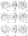
- FIGS 7a, 7b and 7c show the device in the safety position.
- the flap 7 comprises sectors having colored marks making it possible to visualize from the outside of the explosive device 1 the state of the device 8.
- the visualization of the state is done through windows 47 which advantageously are arranged in the housing of the machine 1 in at least three directions so as to facilitate remote identification of the armed state or not of the machine.
- the double hatching sector in the figures (green in reality) means that the device is in a safety position.
- the sector with hexagonal patterns in the figures means that the device is in the sterilization position (this will be specified with reference to Figures 16a, 16b and 16c ).
- the sector with simple hatching in the figures means that the device is in the armed position.
- the different figures also show the location of the pyrotechnic component 5 as well as that of the indexing pin 40 relative to the rotor 25.
- the bell cam 34 (not visible) is fixed relative to the upper plate 18a.
- the cam 34 therefore does not rotate with the flap 7 and the rotor 25.
- the projecting part 43 of the bell cam 34 is positioned upwards, below the screw. 11b, while the junction between the flat area 45 and the start of the slope 46 is located opposite the worm. This means that, in the figures, when the pin 40 is next to the worm 11b, it is outside the housing of the rotor 25 (rotor disengaged).
- FIGS. 8a, 8b and 8c show the device being armed. Initially, the motor 11 was controlled by the control unit 22. The rotor 25 being disengaged, the motor 11 rotates the cover 37 until the pin 40 is introduced into the housing 30a or 30b which is free. The motor pinion 16 is then coupled to the flap 7 and the flap, driven by the motor 11, rotates in the direction of the arrow A. We note on the figure 8a that this pivoting causes the winding pinion 15 to rotate (direction of the arrow C1) which is driven by the indicator pinion 13 secured to the flap 7.
- the pyrotechnic component 5 begins to appear opposite the opening 24 and the light 12.
- FIGS. 9a, 9b and 9c show the device in the armed position.
- the control unit computer has information relating to the angular position of the flap 7, a position which is given to it by a rotation sensor mounted at the end of the shaft 20 (not shown).
- the single-hatch sector of the flap 7 occupies all the status display windows 47. Furthermore, the pin 40 is ejected from the housing of the rotor 25 (rotor 25 disengaged).
- the machine can be disarmed at the request of a user by a specific command addressed to the control unit 22.
- the figure 10 shows the start of a voluntary disarmament (DV) phase controlled by an operator, for example using a remote control.
- DV voluntary disarmament
- the figure 10 does differ from the figure 9c only by the angular positioning of the cap 37.
- the motor means 11 is actuated with a rotation in the same direction as that which led to the arming.
- the drive means rotates the cover 37.
- the pin 40 which was released from the rotor 25 moves angularly until it engages in another free housing of the rotor ( figure 11c ).
- FIGS 11a, 11b and 11c show the beginning of the flap 7 pivoting movement (arrow DV which has the same direction as arrow A). It can be seen that the pyrotechnic component 5 leaves the opening 24 and the light 12 to gradually position themselves opposite a massive part of the flap 7 (that formed by the indicator pinion 13).
- the Figures 12a, 12b and 12c show the continuation of the pivoting movement of the flap 7. It is noted that the indicator pinion 13 comprises a portion 13a which is devoid of teeth and which therefore no longer interferes with the winding pinion 15. Thus this movement of the flap 7 beyond from the armed position is done without acting on the chronometry module 14, therefore without damaging it. Alternatively it would be possible to provide in the chronometry module a wheel for disengaging the winding pinion 15 during such a phase.
- the pyrotechnic component 5 (located figure 12c ) is now in front of a massive part of shutter 7 and the double-hatched sector of shutter 7 is in the status display windows 47. The machine no longer presents any danger.
- FIGs 13a, 13b and 13c show the device at the end of voluntary disarmament. The device has returned to the safety position and these figures are identical to Figures 7a, 7b and 7c respectively.
- the safety and arming device can automatically return to the safety position after a time interval provided for in the design, regardless of the faults in the control electronics or sources of energy.
- This automatic disarming operation is subsequently designated by the English expression “Fail Safe” (FS) or anti-failure security (this designation well known to those skilled in the art is used in military standards).
- FS Fan Safe
- anti-failure security this designation well known to those skilled in the art is used in military standards.
- the mechanical chronometric module 14 which does not contain a pre-banded spring, is reassembled mechanically during the arming process ( Figures 7a to 9c ).
- the rotor 25 is disengaged, which means that the flap 7 is not blocked by the motor means 11, despite the presence of the worm 11b (irreversible component).
- the declutching therefore occurs automatically as soon as it enters the armed position and by the action of the declutching means 17 described above.
- the chronometric module 14 then acts freely on the shutter 7 by means of the indicator pinion 13 and it turns the shutter 7 in an opposite direction FS from that A corresponding to the arming (arming A at the figure 8c , Fail Safe FS at figure 14c ).
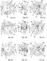
- FIGs 14a, 14b and 14c thus show the device during an intermediate phase of this automatic disarming process (Fail Safe).
- the winding pinion 15 rotates in the direction C2 and drives the flap 7 via the indicator pinion 13.
- the pin 40 remained in its initial position of the figure 9c , while the rotor 25 has rotated with the flap 7.
- the pyrotechnic component 5 is located opposite the light 12 and the opening 24.
- the security and arming device is therefore always in a armed position and the explosive device is operational.
- the single-hatch sector of the shutter 7 occupies the status display windows 47.
- the Figures 15a, 15b and 15c show the device at the end of the automatic disarming process (or Fail Safe).
- the device 6 has returned to its safety position which is identical to that of the Figures 7a, 7b, 7c and 13a, 13b, 13c .
- the chronometric module is then in its rest state, internal spring not bandaged.
- the pyrotechnic component 5 is located opposite a massive part of the flap 7 (opposite indicator pinion 13).
- the pin 40 has disengaged the rotor 25.
- the control unit 22 has short-circuited the pyrotechnic component 5 to prevent any firing of the latter.
- the explosive device can be removed without danger and can be reused at another place of operations.
- the chronometric module 14 will be chosen so as to ensure the desired operating time for the explosive device, for example a duration of the order of 30 minutes to several hours. It is of course possible to modify the activation characteristics of the explosive device 1 by changing the time module 14.
- control unit 22 will cause, for example following an order sent to the control unit 22 over the air, an operating cycle in which the motor means 11 is controlled so as to rotate the motor pinion 16 from the armed position represented on the Figures 9a to 9c , or from another intermediate armed position as shown in the figures 14a to 14c .
- This command of the motor pinion 16 will cause, just as during the voluntary disarming of the device ( figure 10 ), the rotation of the cap 37 until engagement of the pin 40 in the rotor 25.
- the drive means 11 then turns the flap 7 in the direction DV of voluntary disarming (identical to direction A).
- the control unit 22 stops the rotation of the motor when the flap 7 is in the position represented in Figures 16a to 16c . As described above, this position is detected by an angular sensor (not shown).
- the pyrotechnic component 5 is in front of the mass of the indicator pinion 13.
- the control unit 22 then causes the ignition of the pyrotechnic component 5.
- the pyrotechnic effect is stopped by the indicator pinion 13 and the device 8 is sterilized because there is no longer any operational pyrotechnic component.
- the hexagonal pattern sector of the flap 7 then occupies all the status display windows 47, indicating the sterilized state of the device.
Landscapes
- Engineering & Computer Science (AREA)
- General Engineering & Computer Science (AREA)
- Air Bags (AREA)
- Portable Nailing Machines And Staplers (AREA)
Claims (10)
- Umkehrbare Sicherheits- und Scharfschaltvorrichtung (8) für eine Sprengkörper (1), die dazu bestimmt ist, manuell platziert zu werden, wobei die Vorrichtung einen pyrotechnische Kettenunterbrechungsverschluss (7) umfasst, der in Bezug auf eine Achse drehbar gelagert ist und der durch ein Motormittel (11) zwischen einer gesicherten Position und mindestens einer scharfgeschalteten Position gedreht werden kann, die Vorrichtung ist, dadurch gekennzeichnet, dass der Verschluss (7) durch mindestens ein Zahnrad (13) mit einem mechanischen Zeitmessmodul (14) gekoppelt ist, wobei der Übergang des Verschluss (7) von seiner gesicherten Position in seine scharfgeschaltete Position durch die Wirkung des Zahnrads (13) auf ein Aufzugszahnrad (15) des Zeitmessmoduls (14), das Aufziehen des letzten durch dem Verband einer Feder des Zeitmessmoduls verursacht, wobei ein Entriegelungsmittel (17) zum Lösen des Motormittels (11) vorgesehen ist und ermöglicht, dass nach dem der Verschluss (7) in die scharfgeschalete Position bewegt wurde, der Verschluss (7) in verzögerter Weise in die gesicherte Position durch die alleinige Wirkung des auf das Zahnrad (13) wirkenden Zeitmessmoduls (14) zurückkehrt, das zu einer Drehung des Verschluss (7) führt, die die entgegengesetzte Richtung ist, zu derjenigen die zur Scharfschaltung führte.
- Umkehrbare Sicherheits- und Scharfschalteinrichtung nach Anspruch 1, dadurch gekennzeichnet, dass der Verschluss (7) mit einer Welle (20) fest verbunden ist, die koaxial zur Drehachse des Verschluss (7) ist, die über die Entriegelungsmittel (17) mit einem Motorzahnrad (16) verbindbar ist.
- Umkehrbare Sicherheits- und Scharfschalteinrichtung nach Anspruch 2, dadurch gekennzeichnet, dass das Entriegelungsmittel (17) einen Indexierrotor (25) umfasst, der an der den Verschluss (7) tragenden Welle (20) befestigt ist und mindestens zwei zylindrische Gehäuse (30a, 30b) aufweist, deren Achsen parallel zur Achse der Welle (20) sind, und jede nimmt eine Stange (31a, 31b) auf, die gegen die Wirkung einer Stangenfeder (32a, 32b) gleitet, wobei jede Stange ein erstes Ende (33a, 33b) aufweist, das von der Stangenfeder (32a, 32b) gehalten wird, die gegen ein festes Nockenprofil (34) anliegt, und ein zweites Ende (35a, 35b), das den durch das Nockenprofil (34) geschobenen Rotor (25) verlassen kann, um mit einem Indexierstift (40) zusammenzuwirken, der selbst in einem Deckel (37) gleitend montiert ist, der mit dem Motorzahnrad (16) fest verbunden ist, der Indexierstift (40), der von einer Feder (41) in Richtung Rotor (25) gedrückt wird und in eines der zylindrischen Gehäuse (30a, 30b) des Rotors (25) eingreifen kann, um eine Drehverbindung zwischen dem Motorzahnrad (16) und dem Indexierrotor (25) sicherzustellen.
- Umkehrbare Sicherheits- und Scharfschalteinrichtung nach Anspruch 3, dadurch gekennzeichnet, dass der Verschluss (7) drehbar an dem zu ihm koaxialen Zahnrad (13) oder Anzeigezahnrad befestigt ist, das mit einem Aufzugszahnrad (15) des Zeitmessmoduls (14) in Eingriff steht.
- Umkehrbare Sicherheits- und Scharfschalteinrichtung nach einem der Ansprüche 1 bis 4, dadurch gekennzeichnet, dass sie ein elektropyrotechnisches Modul (6) umfasst, das ein elektronisches Zündsteuerungsmittel und eine pyrotechnische Komponente (5) umfasst, die dazu bestimmt ist, eine explosive Belastung eines Gefechtskopfes (2) der Sprengkörper (1) einzuleiten, der Verschluss (7) der Kettenunterbrechung eine teilkreisförmige Öffnung (12, 24) umfasst, die sich gegenüber der pyrotechnischen Komponente (5) befindet, wenn sich die Verschluss in einer scharfgeschalteten Position befindet, wobei sich die pyrotechnische Komponente (5) gegenüber einem massiven Teil der Verschluss (7) befindet, also außerhalb der Öffnung (12, 24), wenn sich der Verschluss (7) in einer gesicherten Position befindet.
- Umkehrbare Sicherheits- und Scharfschalteinrichtung nach den Ansprüchen 4 und 5, dadurch gekennzeichnet, dass die Öffnung (12) des Verschluss von dem Anzeigezahnrad (13) getragen wird, das somit den massiven Teil der Verschluss (7) bildet.
- Umkehrbare Sicherheits- und Scharfschalteinrichtung nach einem der Ansprüche 5 oder 6, dadurch gekennzeichnet, dass der Verschluss (7) jederzeit in der gesicherten Stellung durch eine Steuerung der Motormittel (11) positioniert werden kann, die den Verschluss (7) in die gleiche Richtung drehen, in der sie ihn die scharftgeschaltete Position geführt hat.
- Umkehrbare Sicherheits- und Scharfschalteinrichtung nach den Ansprüchen 4 und 7, dadurch gekennzeichnet, dass das Anzeigezahnrad (13) einen Abschnitt (13a) ohne Zähne umfasst, so dass der Durchgang der Verschluss (7) von der scharfgeschalteten Position in die gesicherte Position ohne Einwirkung auf das Zeitmodul (14) erfolgt.
- Umkehrbare Sicherheits- und Scharfschalteinrichtung nach einem der Ansprüche 5 oder 6, dadurch gekennzeichnet, dass die Verschluss (7) jederzeit in eine Entschärfteposition durch eine Steuerung der Motormittel (11) positioniert werden kann, die den Verschluss (7) in die gleiche Richtung drehen, in die sie in ihn in der scharfgestellten Position geführt hat, wobei die Motormittel (11) in einer Zwischenzone angehalten werden, in der die pyrotechnische Komponente (5) nicht mehr der Öffnung (12) zugewandt ist, wobei die elektronische Zündsteuerungseinrichtung (6) dann die Zündung der Komponente (5) gegenüber einer massiven Zone des Verschluss (7) bewirkt.
- Umkehrbare Sicherheits- und Scharfschalteinrichtung nach einem der Ansprüche 2 bis 9, dadurch gekennzeichnet, dass die Motormittel (11) einen Getriebemotor (11a) umfassen, der das Motorzahnrad (16) durch eine Schnecke (11b) antreibt.
Applications Claiming Priority (2)
| Application Number | Priority Date | Filing Date | Title |
|---|---|---|---|
| FR1502689A FR3045812B1 (fr) | 2015-12-22 | 2015-12-22 | Dispositif de securite et d'armement reversible pour un engin explosif |
| PCT/FR2016/053108 WO2017109313A1 (fr) | 2015-12-22 | 2016-11-25 | Dispositif de securite et d'armement reversible pour un engin explosif |
Publications (2)
| Publication Number | Publication Date |
|---|---|
| EP3394558A1 EP3394558A1 (de) | 2018-10-31 |
| EP3394558B1 true EP3394558B1 (de) | 2020-01-01 |
Family
ID=55806404
Family Applications (1)
| Application Number | Title | Priority Date | Filing Date |
|---|---|---|---|
| EP16825801.0A Active EP3394558B1 (de) | 2015-12-22 | 2016-11-25 | Umkehrbares sicherheits- und bewehrungssystem für eine explosive vorrichtung |
Country Status (3)
| Country | Link |
|---|---|
| EP (1) | EP3394558B1 (de) |
| FR (1) | FR3045812B1 (de) |
| WO (1) | WO2017109313A1 (de) |
Family Cites Families (10)
| Publication number | Priority date | Publication date | Assignee | Title |
|---|---|---|---|---|
| BE411112A (de) * | 1934-09-05 | |||
| US3115834A (en) * | 1944-05-31 | 1963-12-31 | Arthur H Schwarz | Self-winding arming and sterilizing mechanism for a mine |
| FR2174362A6 (de) * | 1968-10-11 | 1973-10-12 | Ruggieri Ets | |
| US3842743A (en) * | 1973-05-29 | 1974-10-22 | C Zittle | Air-driven turbine safe and arm arrangement for a free-falling ordnance device |
| FR2679325B1 (fr) | 1991-07-15 | 1995-02-17 | Giat Ind Sa | Dispositif de securite et d'armement a volet bistable. |
| US5249526A (en) * | 1992-11-12 | 1993-10-05 | The United States Of America As Represented By The Secretary Of The Navy | Safe and arm device |
| FR2793314B1 (fr) | 1996-04-02 | 2002-05-31 | Giat Ind Sa | Charge generatrice de noyau a performances ameliorees |
| FR2749072B1 (fr) * | 1996-05-21 | 1998-07-10 | Giat Ind Sa | Dispositif de securite et d'armement notamment pour mine |
| FR2776060B1 (fr) * | 1998-03-13 | 2000-06-23 | Giat Ind Sa | Mine, notamment antichar ou antivehicule, comportant des moyens de confirmation de la presence d'une cible |
| US6170397B1 (en) * | 1998-08-20 | 2001-01-09 | The United States Of America As Represented By The Secretary Of The Navy | Energetic transmission line completion/interruption mechanism |
-
2015
- 2015-12-22 FR FR1502689A patent/FR3045812B1/fr not_active Expired - Fee Related
-
2016
- 2016-11-25 EP EP16825801.0A patent/EP3394558B1/de active Active
- 2016-11-25 WO PCT/FR2016/053108 patent/WO2017109313A1/fr not_active Ceased
Non-Patent Citations (1)
| Title |
|---|
| None * |
Also Published As
| Publication number | Publication date |
|---|---|
| FR3045812A1 (fr) | 2017-06-23 |
| WO2017109313A1 (fr) | 2017-06-29 |
| EP3394558A1 (de) | 2018-10-31 |
| FR3045812B1 (fr) | 2018-04-06 |
Similar Documents
| Publication | Publication Date | Title |
|---|---|---|
| EP2077431B1 (de) | Mikromechanisch bearbeitete oder mikrogravierte Sicherungs- und Scharfstellungsvorrichtung | |
| EP0687888B1 (de) | Abfeuervorrichtung für eine pyrotechnische Ladung mit einem Zünderkopf, insbesondere für Handgranateur, mit drei Funktionsweisen | |
| EP2482027B1 (de) | Sicherheits- und Zündvorrichtung für eine pyrotechnische Kette eines Geschosses | |
| EP3394558A1 (de) | Umkehrbares sicherheits- und bewehrungssystem für eine explosive vorrichtung | |
| EP0228386B1 (de) | Geschosszünder | |
| EP0756151B1 (de) | Vorrichtung zum Zünden einer Treibladung für eine aus einem Trägergeschoss geworfene Submunition | |
| EP0942257B1 (de) | Mine, insbesondere zur Panzer- oder Fahrzeugbekämpfung, mit Mitteln zur Bestätigung des Vorhandenseins eines Ziels | |
| EP4409223A1 (de) | Mechanischer selbstschlagzünder für eine nicht-spinnende runde | |
| FR2691797A1 (fr) | Système de sécurité et d'armement pour sous-munition, en particulier pour sous-munition embarquée dans un obus cargo. | |
| EP0075496B1 (de) | Vorkehrungen zum Sichern und Schärfen an Unterwasserzündern | |
| EP1524489B1 (de) | Zündvorrichtung und multimode Hohlladung welche einen solchen Zünder verwendet | |
| EP0016701A1 (de) | Sicherheitsvorrichtung für pyrotechnische Elemente | |
| EP0627067B1 (de) | Zünd- und selbstzerlegungssystem für submunition | |
| EP2482028B1 (de) | Sicherheits- und Zündvorrichtung mit einem zerbrechlichen Riegel | |
| EP0463974B1 (de) | Einrichtung zum Sichern und zum Schärfen einer Munition | |
| EP4176225B1 (de) | Zünder mit selbstzerstörungsvorrichtung für ein kreiselgeschoss | |
| EP1500902A1 (de) | Selbst-Zerlegerzünder für drallstabilisierte Geschosse | |
| EP0809085B1 (de) | Sicherheits- und Spannvorrichtung, insbesondere für Minen | |
| EP0320401B1 (de) | Vorrichtung zum Ausrichten mehrerer Elemente entlang einer Linie, insbesondere für eine Zündkette | |
| FR2928723A1 (fr) | Dispositif retardateur a temporisation rapide, equipement additionnel d'augmentation de portee pour bombe guidee incorporant un tel dispositif, et bombe guidee qui en est equipee. | |
| FR2726359A1 (fr) | Fusee d'impact a double securite | |
| EP0991910B1 (de) | Zeitzünder für eine pyrotechnische vorrichtung | |
| FR2634013A1 (fr) | Dispositif de securite et d'armement pour un sous-projectile dispose a l'interieur d'un conteneur et libere par ce dernier sur trajectoire | |
| EP0278837A1 (de) | Zeitzünder für beliebige Aufschlagrichtung für Munition zum Abschuss aus Feuerwaffen, insbesondere für Granaten | |
| FR2679325A1 (fr) | Dispositif de securite et d'armement a volet bistable. |
Legal Events
| Date | Code | Title | Description |
|---|---|---|---|
| STAA | Information on the status of an ep patent application or granted ep patent |
Free format text: STATUS: UNKNOWN |
|
| STAA | Information on the status of an ep patent application or granted ep patent |
Free format text: STATUS: THE INTERNATIONAL PUBLICATION HAS BEEN MADE |
|
| PUAI | Public reference made under article 153(3) epc to a published international application that has entered the european phase |
Free format text: ORIGINAL CODE: 0009012 |
|
| STAA | Information on the status of an ep patent application or granted ep patent |
Free format text: STATUS: REQUEST FOR EXAMINATION WAS MADE |
|
| 17P | Request for examination filed |
Effective date: 20180717 |
|
| AK | Designated contracting states |
Kind code of ref document: A1 Designated state(s): AL AT BE BG CH CY CZ DE DK EE ES FI FR GB GR HR HU IE IS IT LI LT LU LV MC MK MT NL NO PL PT RO RS SE SI SK SM TR |
|
| AX | Request for extension of the european patent |
Extension state: BA ME |
|
| DAV | Request for validation of the european patent (deleted) | ||
| DAX | Request for extension of the european patent (deleted) | ||
| GRAP | Despatch of communication of intention to grant a patent |
Free format text: ORIGINAL CODE: EPIDOSNIGR1 |
|
| STAA | Information on the status of an ep patent application or granted ep patent |
Free format text: STATUS: GRANT OF PATENT IS INTENDED |
|
| INTG | Intention to grant announced |
Effective date: 20190619 |
|
| GRAS | Grant fee paid |
Free format text: ORIGINAL CODE: EPIDOSNIGR3 |
|
| GRAA | (expected) grant |
Free format text: ORIGINAL CODE: 0009210 |
|
| STAA | Information on the status of an ep patent application or granted ep patent |
Free format text: STATUS: THE PATENT HAS BEEN GRANTED |
|
| AK | Designated contracting states |
Kind code of ref document: B1 Designated state(s): AL AT BE BG CH CY CZ DE DK EE ES FI FR GB GR HR HU IE IS IT LI LT LU LV MC MK MT NL NO PL PT RO RS SE SI SK SM TR |
|
| REG | Reference to a national code |
Ref country code: GB Ref legal event code: FG4D Free format text: NOT ENGLISH |
|
| REG | Reference to a national code |
Ref country code: CH Ref legal event code: EP Ref country code: AT Ref legal event code: REF Ref document number: 1220289 Country of ref document: AT Kind code of ref document: T Effective date: 20200115 |
|
| REG | Reference to a national code |
Ref country code: IE Ref legal event code: FG4D Free format text: LANGUAGE OF EP DOCUMENT: FRENCH |
|
| REG | Reference to a national code |
Ref country code: DE Ref legal event code: R096 Ref document number: 602016027550 Country of ref document: DE |
|
| REG | Reference to a national code |
Ref country code: SE Ref legal event code: TRGR |
|
| REG | Reference to a national code |
Ref country code: NL Ref legal event code: MP Effective date: 20200101 |
|
| REG | Reference to a national code |
Ref country code: NO Ref legal event code: T2 Effective date: 20200101 |
|
| REG | Reference to a national code |
Ref country code: LT Ref legal event code: MG4D |
|
| PG25 | Lapsed in a contracting state [announced via postgrant information from national office to epo] |
Ref country code: NL Free format text: LAPSE BECAUSE OF FAILURE TO SUBMIT A TRANSLATION OF THE DESCRIPTION OR TO PAY THE FEE WITHIN THE PRESCRIBED TIME-LIMIT Effective date: 20200101 Ref country code: FI Free format text: LAPSE BECAUSE OF FAILURE TO SUBMIT A TRANSLATION OF THE DESCRIPTION OR TO PAY THE FEE WITHIN THE PRESCRIBED TIME-LIMIT Effective date: 20200101 Ref country code: RS Free format text: LAPSE BECAUSE OF FAILURE TO SUBMIT A TRANSLATION OF THE DESCRIPTION OR TO PAY THE FEE WITHIN THE PRESCRIBED TIME-LIMIT Effective date: 20200101 Ref country code: PT Free format text: LAPSE BECAUSE OF FAILURE TO SUBMIT A TRANSLATION OF THE DESCRIPTION OR TO PAY THE FEE WITHIN THE PRESCRIBED TIME-LIMIT Effective date: 20200527 Ref country code: CZ Free format text: LAPSE BECAUSE OF FAILURE TO SUBMIT A TRANSLATION OF THE DESCRIPTION OR TO PAY THE FEE WITHIN THE PRESCRIBED TIME-LIMIT Effective date: 20200101 Ref country code: LT Free format text: LAPSE BECAUSE OF FAILURE TO SUBMIT A TRANSLATION OF THE DESCRIPTION OR TO PAY THE FEE WITHIN THE PRESCRIBED TIME-LIMIT Effective date: 20200101 |
|
| PG25 | Lapsed in a contracting state [announced via postgrant information from national office to epo] |
Ref country code: LV Free format text: LAPSE BECAUSE OF FAILURE TO SUBMIT A TRANSLATION OF THE DESCRIPTION OR TO PAY THE FEE WITHIN THE PRESCRIBED TIME-LIMIT Effective date: 20200101 Ref country code: BG Free format text: LAPSE BECAUSE OF FAILURE TO SUBMIT A TRANSLATION OF THE DESCRIPTION OR TO PAY THE FEE WITHIN THE PRESCRIBED TIME-LIMIT Effective date: 20200401 Ref country code: GR Free format text: LAPSE BECAUSE OF FAILURE TO SUBMIT A TRANSLATION OF THE DESCRIPTION OR TO PAY THE FEE WITHIN THE PRESCRIBED TIME-LIMIT Effective date: 20200402 Ref country code: IS Free format text: LAPSE BECAUSE OF FAILURE TO SUBMIT A TRANSLATION OF THE DESCRIPTION OR TO PAY THE FEE WITHIN THE PRESCRIBED TIME-LIMIT Effective date: 20200501 Ref country code: HR Free format text: LAPSE BECAUSE OF FAILURE TO SUBMIT A TRANSLATION OF THE DESCRIPTION OR TO PAY THE FEE WITHIN THE PRESCRIBED TIME-LIMIT Effective date: 20200101 |
|
| REG | Reference to a national code |
Ref country code: DE Ref legal event code: R097 Ref document number: 602016027550 Country of ref document: DE |
|
| PG25 | Lapsed in a contracting state [announced via postgrant information from national office to epo] |
Ref country code: SK Free format text: LAPSE BECAUSE OF FAILURE TO SUBMIT A TRANSLATION OF THE DESCRIPTION OR TO PAY THE FEE WITHIN THE PRESCRIBED TIME-LIMIT Effective date: 20200101 Ref country code: EE Free format text: LAPSE BECAUSE OF FAILURE TO SUBMIT A TRANSLATION OF THE DESCRIPTION OR TO PAY THE FEE WITHIN THE PRESCRIBED TIME-LIMIT Effective date: 20200101 Ref country code: SM Free format text: LAPSE BECAUSE OF FAILURE TO SUBMIT A TRANSLATION OF THE DESCRIPTION OR TO PAY THE FEE WITHIN THE PRESCRIBED TIME-LIMIT Effective date: 20200101 Ref country code: DK Free format text: LAPSE BECAUSE OF FAILURE TO SUBMIT A TRANSLATION OF THE DESCRIPTION OR TO PAY THE FEE WITHIN THE PRESCRIBED TIME-LIMIT Effective date: 20200101 Ref country code: ES Free format text: LAPSE BECAUSE OF FAILURE TO SUBMIT A TRANSLATION OF THE DESCRIPTION OR TO PAY THE FEE WITHIN THE PRESCRIBED TIME-LIMIT Effective date: 20200101 Ref country code: RO Free format text: LAPSE BECAUSE OF FAILURE TO SUBMIT A TRANSLATION OF THE DESCRIPTION OR TO PAY THE FEE WITHIN THE PRESCRIBED TIME-LIMIT Effective date: 20200101 |
|
| PLBE | No opposition filed within time limit |
Free format text: ORIGINAL CODE: 0009261 |
|
| STAA | Information on the status of an ep patent application or granted ep patent |
Free format text: STATUS: NO OPPOSITION FILED WITHIN TIME LIMIT |
|
| REG | Reference to a national code |
Ref country code: AT Ref legal event code: MK05 Ref document number: 1220289 Country of ref document: AT Kind code of ref document: T Effective date: 20200101 |
|
| 26N | No opposition filed |
Effective date: 20201002 |
|
| PG25 | Lapsed in a contracting state [announced via postgrant information from national office to epo] |
Ref country code: AT Free format text: LAPSE BECAUSE OF FAILURE TO SUBMIT A TRANSLATION OF THE DESCRIPTION OR TO PAY THE FEE WITHIN THE PRESCRIBED TIME-LIMIT Effective date: 20200101 |
|
| PG25 | Lapsed in a contracting state [announced via postgrant information from national office to epo] |
Ref country code: SI Free format text: LAPSE BECAUSE OF FAILURE TO SUBMIT A TRANSLATION OF THE DESCRIPTION OR TO PAY THE FEE WITHIN THE PRESCRIBED TIME-LIMIT Effective date: 20200101 Ref country code: PL Free format text: LAPSE BECAUSE OF FAILURE TO SUBMIT A TRANSLATION OF THE DESCRIPTION OR TO PAY THE FEE WITHIN THE PRESCRIBED TIME-LIMIT Effective date: 20200101 |
|
| PG25 | Lapsed in a contracting state [announced via postgrant information from national office to epo] |
Ref country code: MC Free format text: LAPSE BECAUSE OF FAILURE TO SUBMIT A TRANSLATION OF THE DESCRIPTION OR TO PAY THE FEE WITHIN THE PRESCRIBED TIME-LIMIT Effective date: 20200101 |
|
| REG | Reference to a national code |
Ref country code: CH Ref legal event code: PL |
|
| PG25 | Lapsed in a contracting state [announced via postgrant information from national office to epo] |
Ref country code: LU Free format text: LAPSE BECAUSE OF NON-PAYMENT OF DUE FEES Effective date: 20201125 |
|
| REG | Reference to a national code |
Ref country code: BE Ref legal event code: MM Effective date: 20201130 |
|
| PG25 | Lapsed in a contracting state [announced via postgrant information from national office to epo] |
Ref country code: LI Free format text: LAPSE BECAUSE OF NON-PAYMENT OF DUE FEES Effective date: 20201130 Ref country code: CH Free format text: LAPSE BECAUSE OF NON-PAYMENT OF DUE FEES Effective date: 20201130 |
|
| PG25 | Lapsed in a contracting state [announced via postgrant information from national office to epo] |
Ref country code: IE Free format text: LAPSE BECAUSE OF NON-PAYMENT OF DUE FEES Effective date: 20201125 |
|
| PG25 | Lapsed in a contracting state [announced via postgrant information from national office to epo] |
Ref country code: TR Free format text: LAPSE BECAUSE OF FAILURE TO SUBMIT A TRANSLATION OF THE DESCRIPTION OR TO PAY THE FEE WITHIN THE PRESCRIBED TIME-LIMIT Effective date: 20200101 Ref country code: MT Free format text: LAPSE BECAUSE OF FAILURE TO SUBMIT A TRANSLATION OF THE DESCRIPTION OR TO PAY THE FEE WITHIN THE PRESCRIBED TIME-LIMIT Effective date: 20200101 Ref country code: CY Free format text: LAPSE BECAUSE OF FAILURE TO SUBMIT A TRANSLATION OF THE DESCRIPTION OR TO PAY THE FEE WITHIN THE PRESCRIBED TIME-LIMIT Effective date: 20200101 |
|
| PG25 | Lapsed in a contracting state [announced via postgrant information from national office to epo] |
Ref country code: MK Free format text: LAPSE BECAUSE OF FAILURE TO SUBMIT A TRANSLATION OF THE DESCRIPTION OR TO PAY THE FEE WITHIN THE PRESCRIBED TIME-LIMIT Effective date: 20200101 Ref country code: AL Free format text: LAPSE BECAUSE OF FAILURE TO SUBMIT A TRANSLATION OF THE DESCRIPTION OR TO PAY THE FEE WITHIN THE PRESCRIBED TIME-LIMIT Effective date: 20200101 |
|
| PG25 | Lapsed in a contracting state [announced via postgrant information from national office to epo] |
Ref country code: BE Free format text: LAPSE BECAUSE OF NON-PAYMENT OF DUE FEES Effective date: 20201130 |
|
| PGFP | Annual fee paid to national office [announced via postgrant information from national office to epo] |
Ref country code: GB Payment date: 20231019 Year of fee payment: 8 |
|
| PGFP | Annual fee paid to national office [announced via postgrant information from national office to epo] |
Ref country code: SE Payment date: 20231020 Year of fee payment: 8 Ref country code: NO Payment date: 20231023 Year of fee payment: 8 Ref country code: IT Payment date: 20231019 Year of fee payment: 8 Ref country code: FR Payment date: 20231019 Year of fee payment: 8 Ref country code: DE Payment date: 20231019 Year of fee payment: 8 |
|
| REG | Reference to a national code |
Ref country code: DE Ref legal event code: R119 Ref document number: 602016027550 Country of ref document: DE |
|
| REG | Reference to a national code |
Ref country code: SE Ref legal event code: EUG |
|
| PG25 | Lapsed in a contracting state [announced via postgrant information from national office to epo] |
Ref country code: NO Free format text: LAPSE BECAUSE OF NON-PAYMENT OF DUE FEES Effective date: 20241130 |
|
| GBPC | Gb: european patent ceased through non-payment of renewal fee |
Effective date: 20241125 |
|
| PG25 | Lapsed in a contracting state [announced via postgrant information from national office to epo] |
Ref country code: DE Free format text: LAPSE BECAUSE OF NON-PAYMENT OF DUE FEES Effective date: 20250603 |
|
| PG25 | Lapsed in a contracting state [announced via postgrant information from national office to epo] |
Ref country code: IT Free format text: LAPSE BECAUSE OF NON-PAYMENT OF DUE FEES Effective date: 20241125 Ref country code: SE Free format text: LAPSE BECAUSE OF NON-PAYMENT OF DUE FEES Effective date: 20241126 |
|
| PG25 | Lapsed in a contracting state [announced via postgrant information from national office to epo] |
Ref country code: GB Free format text: LAPSE BECAUSE OF NON-PAYMENT OF DUE FEES Effective date: 20241125 |
|
| PG25 | Lapsed in a contracting state [announced via postgrant information from national office to epo] |
Ref country code: FR Free format text: LAPSE BECAUSE OF NON-PAYMENT OF DUE FEES Effective date: 20241130 |