EP3394337B1 - Waschmittelspender für wäschebehandlungsgerät - Google Patents
Waschmittelspender für wäschebehandlungsgerät Download PDFInfo
- Publication number
- EP3394337B1 EP3394337B1 EP16879846.0A EP16879846A EP3394337B1 EP 3394337 B1 EP3394337 B1 EP 3394337B1 EP 16879846 A EP16879846 A EP 16879846A EP 3394337 B1 EP3394337 B1 EP 3394337B1
- Authority
- EP
- European Patent Office
- Prior art keywords
- washing machine
- storage cartridge
- chamber
- clothes washing
- treating chemistry
- Prior art date
- Legal status (The legal status is an assumption and is not a legal conclusion. Google has not performed a legal analysis and makes no representation as to the accuracy of the status listed.)
- Active
Links
- 239000003599 detergent Substances 0.000 title claims description 46
- 238000003860 storage Methods 0.000 claims description 82
- XLYOFNOQVPJJNP-UHFFFAOYSA-N water Substances O XLYOFNOQVPJJNP-UHFFFAOYSA-N 0.000 claims description 68
- 239000007788 liquid Substances 0.000 claims description 65
- 238000005406 washing Methods 0.000 claims description 51
- 239000000843 powder Substances 0.000 claims description 35
- 230000008878 coupling Effects 0.000 claims description 18
- 238000010168 coupling process Methods 0.000 claims description 18
- 238000005859 coupling reaction Methods 0.000 claims description 18
- 239000002979 fabric softener Substances 0.000 claims description 4
- 230000007246 mechanism Effects 0.000 description 8
- 230000001133 acceleration Effects 0.000 description 4
- 239000003795 chemical substances by application Substances 0.000 description 4
- 230000000694 effects Effects 0.000 description 2
- 230000006870 function Effects 0.000 description 2
- 230000005484 gravity Effects 0.000 description 2
- 238000010438 heat treatment Methods 0.000 description 2
- 239000000203 mixture Substances 0.000 description 2
- 239000007921 spray Substances 0.000 description 2
- 239000004094 surface-active agent Substances 0.000 description 2
- 102000004190 Enzymes Human genes 0.000 description 1
- 108090000790 Enzymes Proteins 0.000 description 1
- 239000004909 Moisturizer Substances 0.000 description 1
- 239000003242 anti bacterial agent Substances 0.000 description 1
- 239000003990 capacitor Substances 0.000 description 1
- 239000003638 chemical reducing agent Substances 0.000 description 1
- 238000004140 cleaning Methods 0.000 description 1
- 230000009977 dual effect Effects 0.000 description 1
- 238000000605 extraction Methods 0.000 description 1
- 239000012530 fluid Substances 0.000 description 1
- 239000003205 fragrance Substances 0.000 description 1
- 230000006698 induction Effects 0.000 description 1
- 239000003112 inhibitor Substances 0.000 description 1
- 239000000463 material Substances 0.000 description 1
- 238000000034 method Methods 0.000 description 1
- 230000001333 moisturizer Effects 0.000 description 1
- 230000003134 recirculating effect Effects 0.000 description 1
- 230000009467 reduction Effects 0.000 description 1
- 230000004044 response Effects 0.000 description 1
- 238000004513 sizing Methods 0.000 description 1
- 238000005507 spraying Methods 0.000 description 1
- -1 stain repellants Substances 0.000 description 1
- 239000000126 substance Substances 0.000 description 1
- 239000000725 suspension Substances 0.000 description 1
- 239000011782 vitamin Substances 0.000 description 1
- 229940088594 vitamin Drugs 0.000 description 1
- 229930003231 vitamin Natural products 0.000 description 1
- 235000013343 vitamin Nutrition 0.000 description 1
- 238000003466 welding Methods 0.000 description 1
- 230000037303 wrinkles Effects 0.000 description 1
Images




Classifications
-
- D—TEXTILES; PAPER
- D06—TREATMENT OF TEXTILES OR THE LIKE; LAUNDERING; FLEXIBLE MATERIALS NOT OTHERWISE PROVIDED FOR
- D06F—LAUNDERING, DRYING, IRONING, PRESSING OR FOLDING TEXTILE ARTICLES
- D06F39/00—Details of washing machines not specific to a single type of machines covered by groups D06F9/00 - D06F27/00
- D06F39/02—Devices for adding soap or other washing agents
- D06F39/022—Devices for adding soap or other washing agents in a liquid state
-
- D—TEXTILES; PAPER
- D06—TREATMENT OF TEXTILES OR THE LIKE; LAUNDERING; FLEXIBLE MATERIALS NOT OTHERWISE PROVIDED FOR
- D06F—LAUNDERING, DRYING, IRONING, PRESSING OR FOLDING TEXTILE ARTICLES
- D06F39/00—Details of washing machines not specific to a single type of machines covered by groups D06F9/00 - D06F27/00
- D06F39/02—Devices for adding soap or other washing agents
-
- D—TEXTILES; PAPER
- D06—TREATMENT OF TEXTILES OR THE LIKE; LAUNDERING; FLEXIBLE MATERIALS NOT OTHERWISE PROVIDED FOR
- D06F—LAUNDERING, DRYING, IRONING, PRESSING OR FOLDING TEXTILE ARTICLES
- D06F39/00—Details of washing machines not specific to a single type of machines covered by groups D06F9/00 - D06F27/00
- D06F39/12—Casings; Tubs
-
- D—TEXTILES; PAPER
- D06—TREATMENT OF TEXTILES OR THE LIKE; LAUNDERING; FLEXIBLE MATERIALS NOT OTHERWISE PROVIDED FOR
- D06F—LAUNDERING, DRYING, IRONING, PRESSING OR FOLDING TEXTILE ARTICLES
- D06F39/00—Details of washing machines not specific to a single type of machines covered by groups D06F9/00 - D06F27/00
- D06F39/08—Liquid supply or discharge arrangements
- D06F39/088—Liquid supply arrangements
Definitions
- the detergent dispensing system of automatic washing machines mostly adopts the method of dispensing from the front drawer, which is to arrange a drawer in the upper left area of the front panel of a washing machine. Inside the drawer, there are several chambers to load detergents. Washing machines with automatic dispensing functions in the market commonly adopt this kind of design, wherein the drawer or the storage cartridge is removed in a horizontal direction.
- Document US 2013/240049 A1 discloses a household cleaning appliance having a treating chamber and a bulk dispensing system having a removable cartridge configured to contain a treating chemistry, the bulk dispensing system configured to deliver a charge of treating chemistry to the treating chamber.
- One aspect of the invention relates to a clothes washing machine comprising a cabinet defining an interior and having a top wall with a dispenser opening, a tub located within the interior; a drum located within the tub; a water inlet box located within the interior and having at least one storage cartridge chamber accessible through the dispenser opening, and at least one powder detergent chamber accessible through the dispenser opening and fluidly coupled to the tub.
- the storage cartridge removably mountable within the storage cartridge chamber through the dispenser opening, at least one liquid coupling having a first connector provided on the storage cartridge and a second connector provided in the storage cartridge chamber, with the first and second connectors coupling when the storage cartridge is mounted within the storage cartridge chamber to establish a liquid connection, at least one metering pump having an inlet fluidly coupled to the second connector and an outlet fluidly coupled to the water inlet box, a water supply line fluidly coupled to the water inlet box to flush at least the powder detergent chamber, and a cover movably mounted relative to the cabinet to selectively open/close the dispenser opening.
- a clothes washing machine comprising a cabinet defining an interior and having a top wall with a dispenser opening, a water inlet box located within the interior and having at least one storage cartridge chamber accessible through the dispenser opening, and at least one powder detergent chamber accessible through the dispenser opening.
- a storage cartridge removably mountable within the storage cartridge chamber through the dispenser opening having at least two fluidly isolated bulk treating chemistry chambers, and a handle mounted to the storage compartment wherein a user can grasp the handle to vertically move the storage cartridge to raise/lower the cartridge in/out of the storage cartridge chamber through the dispenser opening in the top wall of the cabinet.
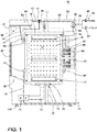
- FIG. 1 shows a laundry treating appliance in accordance with the present disclosure, which happens to be a horizontal axis automatic clothes washing machine 10.
- FIG. 1 shows a laundry treating appliance in accordance with the present disclosure, which happens to be a horizontal axis automatic clothes washing machine 10.
- the present disclosure encompasses other environments, including other horizontal axis laundry treating appliances such as a laundry dryer.
- other loading configurations, such as top-loading are contemplated.
- a vertical axis laundry treating appliance is contemplated in addition to the illustrated horizontal axis laundry treating appliance.
- the terms horizontal axis and vertical axis are used to represent the general orientation of the axis of rotation and is not meant to be limited to a perfectly horizontal or vertical axis of rotation. More accurately, the terms horizontal axis of rotation or vertical axis of rotation, when used to identify the type of laundry treating appliance, are more accurately used to describe the primary mechanism by which mechanical energy is imparted to the laundry.
- the horizontal axis washing machine imparts mechanical energy primarily by tumbling the laundry within the drum. That is, rotation of the drum lifts and then drops the laundry. This lifting/dropping imparts mechanical energy to the laundry.
- the vertical axis washing machine imparts mechanical energy via a clothes mover, such as an agitator, impeller, pulsator, auger, etc., which is rotated within the basket to effect movement of liquid in the basket or directly impact the laundry.
- a clothes mover such as an agitator, impeller, pulsator, auger, etc.
- drum and basket are interchangeable.
- the laundry treating appliance of FIG. 1 is illustrated as a front-loading, horizontal-axis washing machine 10, which may include a structural support system comprising a cabinet 12 which defines a housing within which a laundry holding system resides and includes a top wall 13.
- the cabinet 12 may be a housing having a chassis and/or a frame, defining an interior enclosing components typically found in a conventional washing machine, such as motors, pumps, fluid lines, controls, sensors, transducers, and the like. Such components will not be described further herein except as necessary for a complete understanding of the invention.
- the laundry holding system comprises a tub 14 supported within the cabinet 12 by a suitable suspension system 28 and a drum 16 provided within the tub 14, the drum 16 defining at least a portion of a laundry treating chamber 18.
- the drum 16 may include a plurality of perforations 20 such that liquid may flow between the tub 14 and the drum 16 through the perforations 20.
- a plurality of baffles 22 may be disposed on an inner surface of the drum 16 to lift the laundry load received in the treating chamber 18 while the drum 16 rotates. It is also within the scope of the invention for the laundry holding system to comprise only a tub with the tub defining the laundry treating chamber.
- the laundry holding system may further include a door 24 which may be movably mounted to the cabinet 12 to selectively close both the tub 14 and the drum 16.
- the washing machine 10 can further include a liquid supply system for supplying water to the washing machine 10 for use in treating laundry during a cycle of operation.
- the liquid supply system can include a source of water, such as a household water supply 40, which can include separate valves 42 and 44 for controlling the flow of hot and cold water, respectively.
- Water can be supplied through an inlet conduit 46 directly to the tub 14 by controlling first and second diverter mechanisms 48 and 50, respectively.
- the diverter mechanisms 48, 50 can be a diverter valve having two outlets such that the diverter mechanisms 48, 50 and can selectively direct a flow of liquid to one or both of two flow paths.
- Water from the household water supply 40 can flow through the inlet conduit 46 to the first diverter mechanism 48 which can direct the flow of liquid to a supply conduit 52.
- the second diverter mechanism 50 on the supply conduit 52 can direct the flow of liquid to a tub outlet conduit 54 which can be provided with a spray nozzle 56 configured to spray the flow of liquid into the tub 14. In this manner, water from the household water supply 40 can be supplied directly to the tub 14.
- the washing machine 10 can also be provided with a dispensing system for dispensing treating chemistry to the treating chamber 18 for use in treating the laundry according to a cycle of operation.
- the dispensing system can include a dispenser 62, which can be a single use dispenser, a bulk dispenser or a combination of a single use and bulk dispenser.
- the dispenser 62 can be configured to dispense a treating chemistry directly to the tub 14 or mixed with water from the liquid supply system through a dispensing outlet conduit 64.
- the dispensing outlet conduit 64 can include a dispensing nozzle 66 configured to dispense the treating chemistry into the tub 14 in a desired pattern and under a desired amount of pressure.
- the dispensing nozzle 66 can be configured to dispense a flow or stream of treating chemistry into the tub 14 by gravity, i.e. a non-pressurized stream.
- Water can be supplied to the dispenser 62 from the supply conduit 52 by directing the second diverter mechanism 50 to direct the flow of water to a dispensing supply conduit 68.
- Non-limiting examples of treating chemistries that can be dispensed by the dispensing system during a cycle of operation include one or more of the following: water, detergents, surfactants, enzymes, fragrances, stiffness/sizing agents, wrinkle releasers/reducers, softeners, antistatic or electrostatic agents, stain repellants, water repellants, energy reduction/extraction aids, antibacterial agents, medicinal agents, vitamins, moisturizers, shrinkage inhibitors, and color fidelity agents, and combinations thereof.
- the treating chemistries can be in the form of a liquid, powder, or any other suitable phase or state of matter.
- the washing machine 10 can also include a recirculation and drain system for recirculating liquid within the laundry holding system and draining liquid from the washing machine 10.
- Liquid supplied to the tub 14 through tub outlet conduit 54 and/or the dispensing supply conduit 68 typically enters a space between the tub 14 and the drum 16 and can flow by gravity to a sump 70 formed in part by a lower portion of the tub 14.
- the sump 70 can also be formed by a sump conduit 72 that can fluidly couple the lower portion of the tub 14 to a pump 74.
- the pump 74 can direct liquid to a drain conduit 76, which can drain the liquid from the washing machine 10, or to a recirculation conduit 78, which can terminate at a recirculation inlet 80.
- the recirculation inlet 80 can direct the liquid from the recirculation conduit 78 into the drum 16.
- the recirculation inlet 80 can introduce the liquid into the drum 16 in any suitable manner, such as by spraying, dripping, or providing a steady flow of liquid. In this manner, liquid provided to the tub 14, with or without treating chemistry can be recirculated into the treating chamber 18 for treating the laundry within.
- the liquid supply and/or recirculation and drain system can be provided with a heating system which can include one or more devices for heating laundry and/or liquid supplied to the tub 14, such as a steam generator 82 and/or a sump heater 84.
- a heating system which can include one or more devices for heating laundry and/or liquid supplied to the tub 14, such as a steam generator 82 and/or a sump heater 84.
- Liquid from the household water supply 40 controlling the first diverter mechanism 48 to direct the flow of liquid to a steam supply conduit 86.
- Steam generated by the steam generator 82 can be supplied to the tub 14 through a steam outlet conduit 87.
- the steam generator 82 can be any suitable type of steam generator such as a flow through steam generator or a tank-type steam generator.
- the sump heater 84 can be used to generate steam in place of or in addition to the steam generator 82.
- the steam generator 82 and/or sump heater 84 can be used to heat the laundry and/or liquid within the tub 14 as part of
- liquid supply and recirculation and drain system can differ from the configuration shown in FIG. 1 , such as by inclusion of other valves, conduits, treating chemistry dispensers, sensors, such as water level sensors and temperature sensors, and the like, to control the flow of liquid through the washing machine 10 and for the introduction of more than one type of treating chemistry.
- the washing machine 10 also includes a drive system for rotating the drum 16 within the tub 14.
- the drive system can include a motor 88 for rotationally driving the drum 16.
- the motor 88 can be directly coupled with the drum 16 through a drive shaft 90 to rotate the drum 16 about a rotational axis during a cycle of operation.
- the motor 88 can be a brushless permanent magnet (BPM) motor having a stator 92 and a rotor 94. Alternately, the motor 88 can be coupled with the drum 16 through a belt and a drive shaft 90 to rotate the drum 16, as is known in the art.
- Other motors such as an induction motor or a permanent split capacitor (PSC) motor, can also be used.
- the motor 88 can rotationally drive the drum 16 including that the motor 88 can rotate the drum 16 at various speeds in either rotational direction.
- the motor 88 can be configured to rotatably drive the drum 16 in response to a motor control signal.
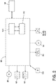
- the washing machine 10 also includes a control system for controlling the operation of the washing machine 10 to implement one or more cycles of operation.
- the control system can include a controller 96 located within the cabinet 12 and a user interface 98 that is operably coupled with the controller 96.
- the user interface 98 can include one or more knobs, dials, switches, displays, touch screens, and the like for communicating with the user, such as to receive input and provide output.
- the user can enter different types of information including, without limitation, laundry treating chemistry concentration and cycle selection and cycle parameters, such as cycle options.
- the controller 96 can include the machine controller and any additional controllers provided for controlling any of the components of the washing machine 10.
- the controller 96 can include the machine controller and a motor controller.
- Many known types of controllers can be used for the controller 96. It is contemplated that the controller can be a microprocessor-based controller that implements control software and sends/receives one or more electrical signals to/from each of the various working components to effect the control software.
- the controller 96 can also be coupled with one or more sensors 103, 104 provided in one or more of the systems of the washing machine 10 to receive input from the sensors.
- sensors 103, 104 that can be communicably coupled with the controller 96 include: a surfactant sensor, a turbidity sensor, a motor torque sensor, a pressure sensor, a conductivity sensor, a treating chamber temperature sensor, a moisture sensor, a weight sensor, a chemical sensor, a position sensor, an acceleration sensor, a speed sensor, an orientation sensor, an imbalance sensor, a load size sensor, and, which can be used to determine a variety of system and laundry characteristics, such as over-sudsing conditions.
- a motor torque sensor, a speed sensor, an acceleration sensor, and/or a position sensor can also be included in the washing machine 10 and can provide an output or signal indicative of the torque applied by the motor, a speed of the drum 16 or component of the drive system, an acceleration of the drum 16 or component of the drive system, and a position sensor of the drum 16.
- sensors 103, 104 can be any suitable types of sensors including, but not limited to, that one or more of the sensors 103, 104 can be a physical sensor or can be integrated with the motor and combined with the capability of the controller 96 to function as a sensor.
- motor characteristics such as speed, current, voltage, torque etc., can be processed such that the data provides information in the same manner as a separate physical sensor. In contemporary motors, the motors often have their own controller that outputs data for such information.
- the controller 96 can be provided with a memory 101 and a central processing unit (CPU) 102.
- the memory 101 can be used for storing the control software that can be executed by the CPU 102 in completing a cycle of operation using the washing machine 10 and any additional software. Examples, without limitation, of cycles of operation include: wash, heavy duty wash, delicate wash, quick wash, pre-wash, refresh, rinse only, and timed wash.
- the memory 101 can also be used to store information, such as a database or table, and to store data received from one or more components or sensors 103, 104 of the washing machine 10 that can be communicably coupled with the controller 96.
- the database or table can be used to store the various operating parameters for the one or more cycles of operation, including factory default values for the operating parameters and any adjustments to them by the control system or by user input.
- Such operating parameters and information stored in the memory 101 can include, but are not limited to, threshold values, predetermined criteria, acceleration ramps, etc.
- the controller 96 can be operably coupled with one or more components of the washing machine 10 for communicating with and controlling the operation of the component to complete a cycle of operation.
- the controller 96 can be operably coupled with the motor 88, the pump 74, the dispenser 62, the steam generator 82 and the sump heater 84 to control the operation of these and other components to implement one or more of the cycles of operation.
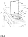
- the dispenser 100 includes a water inlet box 112.
- the water inlet box 112 can include a storage cartridge 118 having fill opening lids 154 and a handle 156, a powder detergent chamber 116, and a cover 134.
- the water inlet box 112 is installed on the left front area of the top wall 13 of the cabinet 12 of the washing machine 10.
- the powder detergent chamber 116 In the front of the water inlet box 112 is the powder detergent chamber 116, a chamber is designed for manual dispensing that can receive either powder or liquid detergent.
- a storage cartridge chamber 114 is used for inserting the storage cartridge 118.
- the cover 134 is movably mounted relative to the cabinet 12 to selectively open and close a dispenser opening 110.
- the storage cartridge chamber 114 and the powder detergent chamber 116 can be accessible through the dispenser opening 110.
- the storage cartridge 118 can have multiple fluidly isolated treating chemistry chambers 142 that can be used to store detergent.
- the treating chemistry chambers 142 can be in the form of a bulk liquid detergent chamber 144 and in the form of a bulk fabric softener chamber 146. While shown in the form of a liquid detergent chamber 144 and a fabric softener chamber 146, the treating chemistry chambers 142 can include dual liquid detergent chambers 144, or any combination of treating chemistry chambers suitable for the desired needs of the user.
- the powder detergent chamber 116 can include a water distributor 136 in the form of a shower head or shower assembly that provides water to flush out powder detergent. As illustrated, the shower head 136 is an annular structure, and can include an annulus 138 circumscribing the powder detergent chamber 116. It is installed and positioned to the water inlet box 112 by jaw and guide ribs 143.
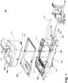
- FIG. 5 illustrates more clearly the storage cartridge 118 including the storage cartridge chamber 114, a decorative cover 115 for the water inlet box 112, metering pumps 126 and pipelines.
- the pipelines include a water supply line 132, metering pump inlets 128, metering pump outlets 130, and a drain outlet 140.
- Each of the treating chemistry chambers 142 includes a fill opening 145 wherein the fill opening lid 154 selectively provides access to the corresponding fill opening 145 so that the treating chemistry chambers 142 are refillable.
- At the front part of the said decorative cover 115 there is a dispensing orifice 116 for dispensing washing powder, and in the rear there is a hollow region for limiting the storage cartridge assembly 114.
- the decorative cover 115 and the water inlet box 112 are fixed with screw connection. The opening area of the cover is installed between the decorative cover 115 and the water inlet box 112 and the cover opening edge is sealed directly with the decorative cover 115.
- Each of the treating chemistry chambers 142 includes a pump connection.
- the pump connection can include the metering pump 126.
- the metering pump inlet 128 can be fluidly coupled to the second connector 124 and a metering pump outlet 130 can be fluidly coupled to the water inlet box 112.
- a water supply line 132 can be fluidly coupled to the water inlet box 112 and the powder detergent chamber 116 to flush at least the powder detergent chamber 116.
- the metering pump outlet 130 can be fluidly coupled to the powder detergent chamber 116.
- the water supply line 132 can terminate in the water distributor 136 fluidly coupled to the powder detergent chamber 116.
- the drain outlet 140 can be located in the powder detergent chamber 116 and be fluidly coupled to the tub 16.
- the metering pump inlet 128 allows the flow of treating chemistry into the metering pump 126 and the metering pump outlet 128 can flow the treating chemistry or a mixture of treating chemistry and water to the powder detergent chamber 116 where the treating chemistry can be flushed with water from the shower head 136.
- a liquid coupling allows treating chemistry to flow from the treating chemistry chamber 124 to the metering pump inlet 128.
- the liquid coupling for each of the treating chemistry chambers 142 includes a first connector 122 provided on the storage cartridge 118 and a second connector 124 provided in the storage cartridge chamber 114.
- the first connector 122 and the second connector 124 couple when the storage cartridge 118 is mounted within the storage chamber 114 to establish a liquid connection.
- the storage cartridge 118 is removably mountable within the storage cartridge chamber 114 and can be removed through the dispenser opening 110 in a vertical direction when a user grasps the handle 156, which decouples the first connector 122 and the second connector 124 of the liquid coupling and raises the storage cartridge 118 out of the storage cartridge chamber 114.
- the storage cartridge 118 can be inserted through the dispenser opening 110 in the top wall 13 of the cabinet 12 when a user lowers the storage cartridge 118 into the storage cartridge chamber 114, which couples the first connector 122 and the second connector 124 of the liquid coupling.
- the handle 156 can be mounted to the storage cartridge 118, and for example, can be pivotally mounted to the storage cartridge 118.
- a handle is provided on the storage lid. The storage cartridge is connected with the storage lid by the jaw and each liquid storage chamber has a floater.
- a liquid level sensor in the form of a floater device 160 is installed to detect the height of the liquid.
- the floater 160 measures the height of the liquid by the distance between magnets 162 and magnetic switches 166.
- One end of the float 160 cooperates with the storage lid axle hole and the two form a cantilever.
- the cavity on the other end and the float cover are sealed by welding, and magnets 162 are installed in the interior space generated; magnetic switches 166 as well as fixed plates 168 for fixing magnetic switches 166 are installed in the corresponding positions at the bottom of the said water inlet box 112.
- the magnets 162 in the liquid level sensor 160 activate the magnetic switches 166, which can turn on a warning light to warn a user of a low liquid level.
- FIG. 7 Another exemplary dispenser 200 according to aspects of the present disclosure is illustrated in FIG. 7 .
- the dispenser 200 is similar to the dispenser 100; therefore, like parts will be identified with like numerals increased by 100, with it being understood that the description of the like parts of the dispenser 100 applies to water inlet box 200, unless otherwise noted.
- the dispenser 200 differs from the dispenser 100 with respect to the metering pumps 226.
- the dispenser 200 includes a water inlet box 212.
- the water inlet box 212 can include a storage cartridge 218 having fill opening lids 254 and a handle 256, and a powder detergent chamber 216.
- a storage cartridge chamber 214 is configured for inserting the storage cartridge 218.
- a cover can be movably mounted relative to the cabinet 12 to selectively open and close a dispenser opening. The storage cartridge chamber 214 and the powder detergent chamber 216 can be accessible through the dispenser opening.
- the storage cartridge 218 can have multiple fluidly isolated treating chemistry chambers 242 that can be used to store detergent.
- the treating chemistry chambers 242 can be in the form of a bulk liquid detergent chamber 244, which can hold any desired treating chemistry, and can be in the form of a bulk fabric softener detergent chamber 246, for example.
- the powder detergent chamber 216 can include a water distributor 236 in the form of a shower head or shower assembly that provides water to flush out powder detergent. As illustrated, the shower head 236 is an annular structure, and can include an annulus 238 circumscribing the powder detergent chamber 216.
- the storage cartridge 218 including the storage cartridge chamber 214, a decorative cover 215 for the water inlet box 212, a first connector 222, metering pumps 226 and pipelines.
- the pipelines include a water supply line 232, metering pump inlets 228, metering pump outlets 230, and a drain outlet 240.
- Each of the treating chemistry chambers 242 includes a fill opening 245 wherein the fill opening lid 254 selectively provides access to the corresponding fill opening 245 so that the treating chemistry chambers 242 are refillable.
- Each of the treating chemistry chambers 242 includes a pump connection.
- the pump connection can include the metering pumps 226.
- Each bulk treating chemistry chamber 242 includes a metering pump 226.
- the metering pumps 226 are on the same side of the dispenser 200 rather than on opposite sides as in dispenser 100. Since the metering pumps 226 are on the same side of the dispenser 200, which is towards the interior of the cabinet 12, the dispenser 200 can fit in a more forward position, towards the exterior, of the top wall 13 of the cabinet 12. It can be advantageous to have the dispenser 200 closer to the exterior of the top wall 13 so that the user can be closer to the dispenser 200.
- the metering pump inlet 228 can be fluidly coupled to the second connector 224 and a metering pump outlet 230 can be fluidly coupled to the water inlet box 212.
- a water supply line 232 can be fluidly coupled to the water inlet box 212 and the powder detergent chamber 216 to flush at least the powder detergent chamber 216.
- the metering pump outlet 230 can be fluidly coupled to the powder detergent chamber 216.
- the water supply line 232 can terminate in the water distributor 236 fluidly coupled to the powder detergent chamber 216.
- the drain outlet 240 can be located in the powder detergent chamber 216 and be fluidly coupled to the tub 16.
- the metering pump inlet 228 allows the flow of treating chemistry into the metering pump 226 and the metering pump outlet 228 can flow the treating chemistry or a mixture of treating chemistry and water to the powder detergent chamber 216 where the treating chemistry can be flushed with water from the shower head 236.
- a liquid coupling allows treating chemistry to flow from the treating chemistry chamber 224 to the metering pump inlet 228.
- the liquid coupling for each of the treating chemistry chambers 242 includes a first connector 222 provided on the storage cartridge 218 and a second connector 224 provided on the storage cartridge chamber 214.
- the first connector 222 and the second connector 224 conjoin when the storage cartridge 218 is mounted within the storage chamber 214 to establish a liquid connection.
- the storage cartridge 218 is removably mountable within the storage cartridge chamber 214 and can be removed through the dispenser opening 210 in a vertical direction when a user grasps the handle 256, which decouples the first connector 222 and the second connector 224 of the liquid coupling and raises the storage cartridge 218 out of the storage cartridge chamber 214.
- the storage cartridge 218 can be inserted through the dispenser opening 210 in the top wall 13 of the cabinet 12 when a user lowers the storage cartridge 218 into the storage cartridge chamber 214, which conjoins the first connector 222 and the second connector 224 of the liquid coupling 270.
- the handle 256 can be mounted to the storage cartridge 218, and for example, can be pivotally mounted to the storage cartridge 218.
- FIG. 8 is an assembled view of the dispenser 200 in FIG. 7 .
- the decorative cover 215 couples the water inlet box 212 and can be fastened with any suitable fastener, such as screws 248.
- the storage cartridge 218 is inserted within the storage cartridge chamber 214, thus the liquid connection is formed.
- FIG. 9A shows a cross-section of the water inlet box 212 along line IX-IX of FIG. 8 to illustrate the liquid coupling 280 more clearly.
- a piston 270 on the second connector 224 abuts a seal 272 having a spring 277 on the first connector 222.
- a gasket 274 circumscribes the seal 272 and is adjacent an inner wall 275 of the first connector 222.
- An outer wall 273 of the first connector includes flexible, annular ribs 278.
- the annular ribs 278 can be constructed of a rubber, or any other suitable material.
- the first connector 222 and the second connector 224 establish the liquid connection when the storage cartridge 218 is inserted within the storage chamber 214.
- the piston 270 on the second connector 224 abuts the seal 272 on the first connector 222.
- the piston 270 counteracts the force from the spring so that the seal 272 moves upwards and gasket 274 is decompressed and does not abut the inner wall 275.
- a channel 276 is formed between the inner wall 275 and the seal 272, which allows treating chemistry to flow to the second connector 224 and the metering pump inlet 228 as indicated by the arrows.
- the annular ribs 278 on the outer wall 273 of the first connector 222 can flex, or bend to fit within the storage cartridge chamber 114 and form a secondary seal between the first connector 222 and the second connector 224.
- FIG. 9B illustrates the liquid coupling 280 of FIG. 9A , uncoupled. While uncoupled, the piston 270 does not abut the seal 272. The spring 277 provides force to compress the gasket 274 so that it abuts the inner wall 275. Thus, the channel 276 is not formed, and the liquid connection is not established. Treating chemistry cannot flow from the first connector 222 to the second connector 224.
- the present invention has designed the water inlet box assembly in the cover region of a washing machine. It makes the design of the front panel simpler. It also features removable storage cartridge assembly which makes it more convenient for users to clean.
- a water inlet box assembly comprising a manual dispenser and a liquid storage cartridge, in the form of a storage cartridge.
- the storage cartridge 118 can be removed in a vertical direction, which allows users to remove and clean the storage cartridge 118. Users can add detergent and softener from the top of the washing machine, and remove the storage cartridge in a vertical direction and clean it. From the above technical scheme, it is thus clear that the present invention has changed the water inlet box design of the washing machine from the prior art and has made it more convenient for users to operate.
Landscapes
- Engineering & Computer Science (AREA)
- Textile Engineering (AREA)
- Detail Structures Of Washing Machines And Dryers (AREA)
Claims (15)
- Kleidungswaschmaschine (10), umfassend:ein Gehäuse (12), das einen Innenraum definiert und eine obere Wand (13) mit einer Spenderöffnung (110) aufweist;einen Wassereinlasskasten (112, 212), der sich innerhalb des Innenraums befindet und mindestens eine Speicherpatronenkammer (114, 214) und mindestens eine Pulverwaschmittelkammer (116, 216), die durch die Spenderöffnung (110) zugänglich sind, aufweist; undeine Speicherpatrone (118, 218), die entfernbar innerhalb der Speicherpatronenkammer (114, 214) durch die Spenderöffnung (110) befestigbar ist und mindestens zwei fluidisch isolierte Massebehandlungschemiekammern (142, 242) aufweist.
- Kleidungswaschmaschine (10) nach Anspruch 1, weiter umfassend einen Deckel (134), der bewegbar bezogen auf das Gehäuse (12) befestigt ist, um die Spenderöffnung (110) selektiv zu öffnen/schließen.
- Kleidungswaschmaschine (10) nach einem der Ansprüche 1-2, wobei die Behandlungschemiekammern (142, 242) nachfüllbar sind.
- Kleidungswaschmaschine (10) nach Anspruch 3, wobei jede von den Behandlungschemiekammern (142, 242) eine Einfüllöffnung (145, 245) und einen entsprechenden Deckel (154, 254), der die Einfüllöffnung (145, 245) selektiv schließt, aufweist.
- Kleidungswaschmaschine (10) nach einem der Ansprüche 1-4, weiter umfassend einen Flüssigkeitspegelsensor (160) in jeder der Behandlungschemiekammern (142, 242).
- Kleidungswaschmaschine (10) nach einem der Ansprüche 1-5, wobei jede der Behandlungschemiekammern (142, 242) einen Pumpenanschluss (126, 226) umfasst.
- Kleidungswaschmaschine (10) nach Anspruch 6, wobei der Pumpenanschluss (126, 226) eine Dosierpumpe (126, 226) ist, die einen Einlass (128, 228), der an ein zweites Anschlussteil (124, 224) in der Speicherpatronenkammer (114, 214) fluidgekoppelt ist, und einen Auslass (130, 230), der an den Wassereinlasskasten (112, 212) fluidgekoppelt ist, aufweist.
- Kleidungswaschmaschine (10) nach Anspruch 7, wobei der Dosierpumpenauslass (130, 230) an die Pulverwaschmittelkammer (116, 216) fluidgekoppelt ist.
- Kleidungswaschmaschine (10) nach einem der Ansprüche 1-8, weiter umfassend eine Wasserversorgungsleitung, die fluidisch (132, 232) an den Wassereinlasskasten (112, 212) gekoppelt ist, um mindestens die Pulverwaschmittelkammer (116, 216) zu spülen.
- Kleidungswaschmaschine (10) nach Anspruch 9, wobei die Wasserversorgungsleitung (132, 232) fluidisch an die Pulverwaschmittelkammer (116, 216) gekoppelt ist.
- Kleidungswaschmaschine (10) nach Anspruch 10, wobei die Wasserversorgungsleitung (132, 232) in einem Wasserverteiler (136, 236) endet, der an die Pulverwaschmittelkammer (116, 216) fluidgekoppelt ist.
- Kleidungswaschmaschine (10) nach Anspruch 11, wobei der Wasserverteiler (136, 236) einen Ring (138, 238) umfasst, der die Pulverwaschmittelkammer (116, 216) umschreibt.
- Kleidungswaschmaschine (10) nach einem der Ansprüche 1-12, wobei zwei Massebehandlungschemiekammern (142, 242) vorhanden sind, eine für Flüssigwaschmittel (144, 244) und eine andere für Gewebeweichmacher (146, 246).
- Kleidungswaschmaschine (10) nach einem der Ansprüche 1-13, weiter umfassend eine Flüssigkeitskupplung für jede der Behandlungschemiekammern.
- Kleidungswaschmaschine nach Anspruch 14, wobei die Flüssigkeitskupplung ein erstes Anschlussteil (122, 222), das an der Speicherpatrone (118, 218) bereitgestellt ist, und ein zweites Anschlussteil (124, 224), das in der Speicherpatronenkammer (114, 214) bereitgestellt ist, umfasst, wobei das erste und das zweite Anschlussteil (122, 124, 222, 224) koppeln, wenn die Speicherpatrone (118, 218) innerhalb der Speicherpatronenkammer (114, 214) befestigt ist, um eine Flüssigkeitsverbindung herzustellen.
Applications Claiming Priority (2)
| Application Number | Priority Date | Filing Date | Title |
|---|---|---|---|
| CN201510981556.8A CN105463787A (zh) | 2015-12-22 | 2015-12-22 | 一种竖直方向抽取储存盒的进水盒组件及其洗衣机 |
| PCT/US2016/064157 WO2017112378A1 (en) | 2015-12-22 | 2016-11-30 | Laundry treating appliance detergent dispenser |
Publications (3)
| Publication Number | Publication Date |
|---|---|
| EP3394337A1 EP3394337A1 (de) | 2018-10-31 |
| EP3394337A4 EP3394337A4 (de) | 2019-10-02 |
| EP3394337B1 true EP3394337B1 (de) | 2020-11-11 |
Family
ID=55601914
Family Applications (1)
| Application Number | Title | Priority Date | Filing Date |
|---|---|---|---|
| EP16879846.0A Active EP3394337B1 (de) | 2015-12-22 | 2016-11-30 | Waschmittelspender für wäschebehandlungsgerät |
Country Status (4)
| Country | Link |
|---|---|
| US (3) | US10988886B2 (de) |
| EP (1) | EP3394337B1 (de) |
| CN (1) | CN105463787A (de) |
| WO (1) | WO2017112378A1 (de) |
Families Citing this family (49)
| Publication number | Priority date | Publication date | Assignee | Title |
|---|---|---|---|---|
| CN105463787A (zh) * | 2015-12-22 | 2016-04-06 | 惠而浦(中国)股份有限公司 | 一种竖直方向抽取储存盒的进水盒组件及其洗衣机 |
| CN106400405B (zh) * | 2016-08-31 | 2018-10-19 | 无锡小天鹅股份有限公司 | 洗衣机的自动投放系统和具有其的洗衣机 |
| CN106222958B (zh) * | 2016-08-31 | 2022-01-18 | 无锡小天鹅电器有限公司 | 用于洗衣机的洗涤剂投放装置、洗涤剂瓶及洗衣机 |
| WO2018040190A1 (zh) * | 2016-08-31 | 2018-03-08 | 无锡小天鹅股份有限公司 | 滚筒洗衣机 |
| CN106436190B (zh) * | 2016-08-31 | 2020-02-18 | 无锡小天鹅电器有限公司 | 洗衣机的自动投放系统和具有其的洗衣机 |
| CN106245277B (zh) * | 2016-08-31 | 2019-05-21 | 无锡小天鹅股份有限公司 | 洗衣机的自动投放系统和具有其的洗衣机 |
| CN106222955B (zh) * | 2016-08-31 | 2018-10-19 | 无锡小天鹅股份有限公司 | 洗衣机的自动投放系统和具有其的洗衣机 |
| CN106436191B (zh) * | 2016-08-31 | 2019-04-16 | 无锡小天鹅股份有限公司 | 洗衣机的洗涤剂投放装置及具有其的洗衣机 |
| CN110770385B (zh) * | 2017-08-23 | 2026-05-01 | 松下知识产权经营株式会社 | 洗衣机 |
| JP2019037721A (ja) * | 2017-08-23 | 2019-03-14 | パナソニックIpマネジメント株式会社 | 洗濯機 |
| JP6751851B2 (ja) * | 2017-08-23 | 2020-09-09 | パナソニックIpマネジメント株式会社 | 洗剤等を自動投入する洗濯機 |
| JP7045609B2 (ja) * | 2017-08-23 | 2022-04-01 | パナソニックIpマネジメント株式会社 | 洗濯機 |
| WO2019044305A1 (ja) * | 2017-09-04 | 2019-03-07 | パナソニックIpマネジメント株式会社 | 洗濯機 |
| CN111051596B (zh) * | 2017-09-04 | 2021-11-16 | 松下知识产权经营株式会社 | 洗衣机 |
| JP6735450B2 (ja) * | 2017-09-04 | 2020-08-05 | パナソニックIpマネジメント株式会社 | 洗濯機 |
| CN111051595A (zh) * | 2017-09-05 | 2020-04-21 | 松下知识产权经营株式会社 | 洗衣机 |
| CN107747194A (zh) * | 2017-11-08 | 2018-03-02 | 无锡小天鹅股份有限公司 | 洗涤用品容纳盒和清洗装置 |
| JP2019107309A (ja) * | 2017-12-20 | 2019-07-04 | パナソニックIpマネジメント株式会社 | 洗濯機 |
| CN109957929B (zh) * | 2017-12-25 | 2023-07-18 | 青岛海尔洗衣机有限公司 | 一种自动投放装置及洗衣机 |
| CN109957932A (zh) * | 2017-12-25 | 2019-07-02 | 青岛海尔洗衣机有限公司 | 一种自动投放装置及洗衣机 |
| CN108060552B (zh) * | 2018-01-17 | 2019-08-27 | 珠海格力电器股份有限公司 | 一种洗涤用品投放装置及洗衣机 |
| JP6893488B2 (ja) * | 2018-04-16 | 2021-06-23 | 日立グローバルライフソリューションズ株式会社 | 洗濯機 |
| JP7235449B2 (ja) * | 2018-07-02 | 2023-03-08 | 東芝ライフスタイル株式会社 | ドラム式洗濯機 |
| CH716539B1 (de) * | 2018-09-06 | 2022-10-14 | V Zug Ag | Waschmittelkartusche und Haushaltgerät. |
| US10876246B2 (en) * | 2018-09-18 | 2020-12-29 | Haier Us Appliance Solutions, Inc. | Level sensor for a bulk dispense tank in a washing machine appliance |
| CN110904630B (zh) * | 2018-09-18 | 2022-11-18 | 重庆海尔滚筒洗衣机有限公司 | 一种洗衣机用洗涤剂盒盖组件及洗衣机 |
| JP2020151036A (ja) * | 2019-03-18 | 2020-09-24 | 東芝ライフスタイル株式会社 | 洗濯機 |
| KR102638183B1 (ko) * | 2019-04-12 | 2024-02-16 | 엘지전자 주식회사 | 세탁기 및 그 제어방법 |
| KR102657349B1 (ko) * | 2019-04-12 | 2024-04-12 | 엘지전자 주식회사 | 세탁기 및 세탁기의 제어방법 |
| JP7623098B2 (ja) * | 2019-06-03 | 2025-01-28 | 東芝ライフスタイル株式会社 | 衣類処理装置 |
| JP7195225B2 (ja) * | 2019-06-26 | 2022-12-23 | 日立グローバルライフソリューションズ株式会社 | 洗濯機 |
| JP7290489B2 (ja) * | 2019-07-08 | 2023-06-13 | 東芝ライフスタイル株式会社 | 衣類処理装置 |
| CN110485133B (zh) * | 2019-08-08 | 2024-08-16 | 青岛海尔洗衣机有限公司 | 一种干衣方法及干衣机 |
| JP7732738B2 (ja) * | 2019-09-20 | 2025-09-02 | 東芝ライフスタイル株式会社 | 洗濯機 |
| US11242642B2 (en) * | 2019-12-19 | 2022-02-08 | Whirlpool Corporation | Laundry treating appliance having a treating chemistry dispenser |
| JP7732742B2 (ja) * | 2020-02-25 | 2025-09-02 | 東芝ライフスタイル株式会社 | 洗濯機用の処理剤タンク及び洗濯機 |
| CN113684652B (zh) * | 2020-05-19 | 2024-02-02 | 重庆海尔滚筒洗衣机有限公司 | 一种衣物处理剂投放装置及衣物处理设备 |
| JP2022029493A (ja) * | 2020-08-05 | 2022-02-18 | シャープ株式会社 | 洗剤投入装置および洗濯機 |
| CN112430984B (zh) * | 2020-11-09 | 2022-07-22 | 海信(山东)冰箱有限公司 | 一种洗衣机 |
| CN112853697A (zh) * | 2021-01-18 | 2021-05-28 | 珠海格力电器股份有限公司 | 一种洗衣机箱体顶盖模块及具有其的洗衣机 |
| JP7652635B2 (ja) * | 2021-06-14 | 2025-03-27 | 東芝ライフスタイル株式会社 | 洗濯機 |
| CN113584813B (zh) * | 2021-08-30 | 2025-01-03 | 无锡小天鹅电器有限公司 | 一种分配器盒、分配器组件、洗涤剂投放装置及洗涤设备 |
| CN116065353B (zh) * | 2021-10-29 | 2025-05-30 | 无锡小天鹅电器有限公司 | 衣物处理装置 |
| US12331451B2 (en) | 2022-02-21 | 2025-06-17 | Haier Us Appliance Solutions, Inc. | Dryer appliance and compartment for non-tumbling items |
| CN116732714A (zh) * | 2022-03-03 | 2023-09-12 | 松下家电(中国)有限公司 | 衣物处理装置 |
| CN114775228B (zh) * | 2022-03-31 | 2025-10-28 | 无锡小天鹅电器有限公司 | 一种洗剂投放装置及衣物处理设备 |
| US12150612B2 (en) | 2022-05-03 | 2024-11-26 | Whirlpool Corporation | Dishwasher and dispenser |
| US12410550B2 (en) | 2022-11-28 | 2025-09-09 | Haier Us Appliance Solutions, Inc. | Laundry appliance door for treatment of non-moving articles |
| DE102023128918A1 (de) * | 2023-10-20 | 2025-04-24 | E.G.O. Elektro-Gerätebau GmbH | Waschmittelverteiler für eine Waschmaschine und Waschmaschine |
Family Cites Families (18)
| Publication number | Priority date | Publication date | Assignee | Title |
|---|---|---|---|---|
| US3567076A (en) | 1967-05-20 | 1971-03-02 | Zanussi A Spa Industrie | Rotary distributor assembly for washing machines |
| US3696970A (en) | 1971-04-23 | 1972-10-10 | Whirlpool Co | Multiple compartment dispenser for a laundry appliance |
| CN100375809C (zh) * | 2002-07-05 | 2008-03-19 | 乐金电子(天津)电器有限公司 | 滚筒洗衣机的洗涤剂注入装置 |
| EP2003237B1 (de) | 2007-06-12 | 2016-05-04 | Electrolux Home Products Corporation N.V. | Waschmaschinenspender für Reinigungsmittel |
| US7950088B2 (en) | 2008-07-01 | 2011-05-31 | Whirlpool Corporation | Method of indicating operational information for a dispensing system having both single use and bulk dispensing |
| US20100000264A1 (en) * | 2008-07-01 | 2010-01-07 | Whirlpool Corporation | Method for converting a household cleaning appliance with a non-bulk dispensing system to a household cleaning appliance with a bulk dispensing system |
| US8052805B2 (en) * | 2008-07-01 | 2011-11-08 | Whirlpool Corporation | Method for automatically flushing a bulk dispensing system in a cleaning appliance |
| IT1393756B1 (it) | 2008-07-28 | 2012-05-08 | Indesit Co Spa | Macchina di lavaggio provvista di serbatoi a lunga carica |
| KR101491574B1 (ko) * | 2008-10-31 | 2015-02-11 | 삼성전자 주식회사 | 세탁기 |
| KR20110004745A (ko) * | 2009-07-08 | 2011-01-14 | 주식회사 대우일렉트로닉스 | 전자동 세탁기의 듀얼세제 투입장치 |
| US8074476B2 (en) | 2009-09-21 | 2011-12-13 | Alliance Laundry Systems Llc | Washer extractor with improved chemical dispenser |
| CN103797178B (zh) * | 2011-09-02 | 2017-05-10 | Lg电子株式会社 | 洗衣机 |
| US8950220B2 (en) * | 2012-01-10 | 2015-02-10 | Ronald Burgess | System for dispensing substances into a washing machine |
| US9353472B2 (en) | 2013-01-07 | 2016-05-31 | General Electric Company | Pedestal in dispenser cups of a washing machine |
| CN103485134B (zh) * | 2013-06-26 | 2017-01-25 | 无锡小天鹅股份有限公司 | 洗衣机及其喷头体组件 |
| BR102013021866B1 (pt) | 2013-08-27 | 2021-12-21 | Whirlpool S.A. | Sistema dispensador valvulado de insumos em forma líquida por ação inercial centrífuga para aparelhos eletrodomésticos |
| CN105463787A (zh) * | 2015-12-22 | 2016-04-06 | 惠而浦(中国)股份有限公司 | 一种竖直方向抽取储存盒的进水盒组件及其洗衣机 |
| CN205443676U (zh) * | 2015-12-22 | 2016-08-10 | 惠而浦(中国)股份有限公司 | 一种竖直方向抽取储存盒的进水盒组件及其洗衣机 |
-
2015
- 2015-12-22 CN CN201510981556.8A patent/CN105463787A/zh active Pending
-
2016
- 2016-11-30 US US15/780,332 patent/US10988886B2/en not_active Expired - Fee Related
- 2016-11-30 EP EP16879846.0A patent/EP3394337B1/de active Active
- 2016-11-30 WO PCT/US2016/064157 patent/WO2017112378A1/en not_active Ceased
-
2021
- 2021-03-17 US US17/203,900 patent/US11591739B2/en active Active
-
2023
- 2023-01-31 US US18/103,581 patent/US12077896B2/en active Active
Non-Patent Citations (1)
| Title |
|---|
| None * |
Also Published As
| Publication number | Publication date |
|---|---|
| US12077896B2 (en) | 2024-09-03 |
| US20180355542A1 (en) | 2018-12-13 |
| US11591739B2 (en) | 2023-02-28 |
| WO2017112378A1 (en) | 2017-06-29 |
| US20230167596A1 (en) | 2023-06-01 |
| US20210198833A1 (en) | 2021-07-01 |
| CN105463787A (zh) | 2016-04-06 |
| EP3394337A1 (de) | 2018-10-31 |
| EP3394337A4 (de) | 2019-10-02 |
| US10988886B2 (en) | 2021-04-27 |
Similar Documents
| Publication | Publication Date | Title |
|---|---|---|
| US12077896B2 (en) | Laundry treating appliance detergent dispenser | |
| US11668044B2 (en) | Method of dispensing treating chemistries in a laundry treating appliance | |
| US9920468B2 (en) | Household cleaning appliance with a non-bulk dispensing system convertible to a household cleaning appliance with a bulk dispensing system | |
| US11767632B2 (en) | Laundry treating appliance having a spray arm assembly | |
| US11739469B2 (en) | Integrated single dose and bulk dispenser for a laundry treating appliance | |
| US11725328B2 (en) | Laundry treating appliance with removable basket | |
| US12091804B2 (en) | Laundry treating appliance and method of dispensing | |
| EP3643830B1 (de) | Wäschebehandlungsgerät mit einem behandlungswerkzeug | |
| EP3486364B1 (de) | Wäschebehandlungsgerät und behandlungschemiespender | |
| US11773527B2 (en) | Laundry treating appliance and dispenser |
Legal Events
| Date | Code | Title | Description |
|---|---|---|---|
| STAA | Information on the status of an ep patent application or granted ep patent |
Free format text: STATUS: THE INTERNATIONAL PUBLICATION HAS BEEN MADE |
|
| PUAI | Public reference made under article 153(3) epc to a published international application that has entered the european phase |
Free format text: ORIGINAL CODE: 0009012 |
|
| STAA | Information on the status of an ep patent application or granted ep patent |
Free format text: STATUS: REQUEST FOR EXAMINATION WAS MADE |
|
| 17P | Request for examination filed |
Effective date: 20180419 |
|
| AK | Designated contracting states |
Kind code of ref document: A1 Designated state(s): AL AT BE BG CH CY CZ DE DK EE ES FI FR GB GR HR HU IE IS IT LI LT LU LV MC MK MT NL NO PL PT RO RS SE SI SK SM TR |
|
| AX | Request for extension of the european patent |
Extension state: BA ME |
|
| DAV | Request for validation of the european patent (deleted) | ||
| DAX | Request for extension of the european patent (deleted) | ||
| A4 | Supplementary search report drawn up and despatched |
Effective date: 20190902 |
|
| RIC1 | Information provided on ipc code assigned before grant |
Ipc: D06F 39/02 20060101AFI20190827BHEP |
|
| GRAP | Despatch of communication of intention to grant a patent |
Free format text: ORIGINAL CODE: EPIDOSNIGR1 |
|
| STAA | Information on the status of an ep patent application or granted ep patent |
Free format text: STATUS: GRANT OF PATENT IS INTENDED |
|
| RIC1 | Information provided on ipc code assigned before grant |
Ipc: D06F 39/02 20060101AFI20200710BHEP Ipc: D06F 39/12 20060101ALI20200710BHEP |
|
| INTG | Intention to grant announced |
Effective date: 20200819 |
|
| GRAS | Grant fee paid |
Free format text: ORIGINAL CODE: EPIDOSNIGR3 |
|
| GRAA | (expected) grant |
Free format text: ORIGINAL CODE: 0009210 |
|
| STAA | Information on the status of an ep patent application or granted ep patent |
Free format text: STATUS: THE PATENT HAS BEEN GRANTED |
|
| AK | Designated contracting states |
Kind code of ref document: B1 Designated state(s): AL AT BE BG CH CY CZ DE DK EE ES FI FR GB GR HR HU IE IS IT LI LT LU LV MC MK MT NL NO PL PT RO RS SE SI SK SM TR |
|
| REG | Reference to a national code |
Ref country code: GB Ref legal event code: FG4D |
|
| REG | Reference to a national code |
Ref country code: CH Ref legal event code: EP |
|
| REG | Reference to a national code |
Ref country code: AT Ref legal event code: REF Ref document number: 1333569 Country of ref document: AT Kind code of ref document: T Effective date: 20201115 |
|
| REG | Reference to a national code |
Ref country code: DE Ref legal event code: R096 Ref document number: 602016047870 Country of ref document: DE |
|
| REG | Reference to a national code |
Ref country code: IE Ref legal event code: FG4D |
|
| REG | Reference to a national code |
Ref country code: NL Ref legal event code: MP Effective date: 20201111 |
|
| REG | Reference to a national code |
Ref country code: AT Ref legal event code: MK05 Ref document number: 1333569 Country of ref document: AT Kind code of ref document: T Effective date: 20201111 |
|
| PG25 | Lapsed in a contracting state [announced via postgrant information from national office to epo] |
Ref country code: GR Free format text: LAPSE BECAUSE OF FAILURE TO SUBMIT A TRANSLATION OF THE DESCRIPTION OR TO PAY THE FEE WITHIN THE PRESCRIBED TIME-LIMIT Effective date: 20210212 Ref country code: FI Free format text: LAPSE BECAUSE OF FAILURE TO SUBMIT A TRANSLATION OF THE DESCRIPTION OR TO PAY THE FEE WITHIN THE PRESCRIBED TIME-LIMIT Effective date: 20201111 Ref country code: NO Free format text: LAPSE BECAUSE OF FAILURE TO SUBMIT A TRANSLATION OF THE DESCRIPTION OR TO PAY THE FEE WITHIN THE PRESCRIBED TIME-LIMIT Effective date: 20210211 Ref country code: PT Free format text: LAPSE BECAUSE OF FAILURE TO SUBMIT A TRANSLATION OF THE DESCRIPTION OR TO PAY THE FEE WITHIN THE PRESCRIBED TIME-LIMIT Effective date: 20210311 Ref country code: RS Free format text: LAPSE BECAUSE OF FAILURE TO SUBMIT A TRANSLATION OF THE DESCRIPTION OR TO PAY THE FEE WITHIN THE PRESCRIBED TIME-LIMIT Effective date: 20201111 |
|
| PG25 | Lapsed in a contracting state [announced via postgrant information from national office to epo] |
Ref country code: SE Free format text: LAPSE BECAUSE OF FAILURE TO SUBMIT A TRANSLATION OF THE DESCRIPTION OR TO PAY THE FEE WITHIN THE PRESCRIBED TIME-LIMIT Effective date: 20201111 Ref country code: BG Free format text: LAPSE BECAUSE OF FAILURE TO SUBMIT A TRANSLATION OF THE DESCRIPTION OR TO PAY THE FEE WITHIN THE PRESCRIBED TIME-LIMIT Effective date: 20210211 Ref country code: PL Free format text: LAPSE BECAUSE OF FAILURE TO SUBMIT A TRANSLATION OF THE DESCRIPTION OR TO PAY THE FEE WITHIN THE PRESCRIBED TIME-LIMIT Effective date: 20201111 Ref country code: LV Free format text: LAPSE BECAUSE OF FAILURE TO SUBMIT A TRANSLATION OF THE DESCRIPTION OR TO PAY THE FEE WITHIN THE PRESCRIBED TIME-LIMIT Effective date: 20201111 Ref country code: IS Free format text: LAPSE BECAUSE OF FAILURE TO SUBMIT A TRANSLATION OF THE DESCRIPTION OR TO PAY THE FEE WITHIN THE PRESCRIBED TIME-LIMIT Effective date: 20210311 Ref country code: AT Free format text: LAPSE BECAUSE OF FAILURE TO SUBMIT A TRANSLATION OF THE DESCRIPTION OR TO PAY THE FEE WITHIN THE PRESCRIBED TIME-LIMIT Effective date: 20201111 |
|
| REG | Reference to a national code |
Ref country code: LT Ref legal event code: MG9D |
|
| PG25 | Lapsed in a contracting state [announced via postgrant information from national office to epo] |
Ref country code: HR Free format text: LAPSE BECAUSE OF FAILURE TO SUBMIT A TRANSLATION OF THE DESCRIPTION OR TO PAY THE FEE WITHIN THE PRESCRIBED TIME-LIMIT Effective date: 20201111 |
|
| REG | Reference to a national code |
Ref country code: CH Ref legal event code: PL |
|
| PG25 | Lapsed in a contracting state [announced via postgrant information from national office to epo] |
Ref country code: RO Free format text: LAPSE BECAUSE OF FAILURE TO SUBMIT A TRANSLATION OF THE DESCRIPTION OR TO PAY THE FEE WITHIN THE PRESCRIBED TIME-LIMIT Effective date: 20201111 Ref country code: SK Free format text: LAPSE BECAUSE OF FAILURE TO SUBMIT A TRANSLATION OF THE DESCRIPTION OR TO PAY THE FEE WITHIN THE PRESCRIBED TIME-LIMIT Effective date: 20201111 Ref country code: CZ Free format text: LAPSE BECAUSE OF FAILURE TO SUBMIT A TRANSLATION OF THE DESCRIPTION OR TO PAY THE FEE WITHIN THE PRESCRIBED TIME-LIMIT Effective date: 20201111 Ref country code: EE Free format text: LAPSE BECAUSE OF FAILURE TO SUBMIT A TRANSLATION OF THE DESCRIPTION OR TO PAY THE FEE WITHIN THE PRESCRIBED TIME-LIMIT Effective date: 20201111 Ref country code: SM Free format text: LAPSE BECAUSE OF FAILURE TO SUBMIT A TRANSLATION OF THE DESCRIPTION OR TO PAY THE FEE WITHIN THE PRESCRIBED TIME-LIMIT Effective date: 20201111 Ref country code: LT Free format text: LAPSE BECAUSE OF FAILURE TO SUBMIT A TRANSLATION OF THE DESCRIPTION OR TO PAY THE FEE WITHIN THE PRESCRIBED TIME-LIMIT Effective date: 20201111 Ref country code: LU Free format text: LAPSE BECAUSE OF NON-PAYMENT OF DUE FEES Effective date: 20201130 |
|
| REG | Reference to a national code |
Ref country code: BE Ref legal event code: MM Effective date: 20201130 |
|
| REG | Reference to a national code |
Ref country code: DE Ref legal event code: R097 Ref document number: 602016047870 Country of ref document: DE |
|
| PG25 | Lapsed in a contracting state [announced via postgrant information from national office to epo] |
Ref country code: DK Free format text: LAPSE BECAUSE OF FAILURE TO SUBMIT A TRANSLATION OF THE DESCRIPTION OR TO PAY THE FEE WITHIN THE PRESCRIBED TIME-LIMIT Effective date: 20201111 Ref country code: LI Free format text: LAPSE BECAUSE OF NON-PAYMENT OF DUE FEES Effective date: 20201130 Ref country code: CH Free format text: LAPSE BECAUSE OF NON-PAYMENT OF DUE FEES Effective date: 20201130 Ref country code: MC Free format text: LAPSE BECAUSE OF FAILURE TO SUBMIT A TRANSLATION OF THE DESCRIPTION OR TO PAY THE FEE WITHIN THE PRESCRIBED TIME-LIMIT Effective date: 20201111 |
|
| REG | Reference to a national code |
Ref country code: IE Ref legal event code: MM4A |
|
| PLBE | No opposition filed within time limit |
Free format text: ORIGINAL CODE: 0009261 |
|
| STAA | Information on the status of an ep patent application or granted ep patent |
Free format text: STATUS: NO OPPOSITION FILED WITHIN TIME LIMIT |
|
| 26N | No opposition filed |
Effective date: 20210812 |
|
| PG25 | Lapsed in a contracting state [announced via postgrant information from national office to epo] |
Ref country code: NL Free format text: LAPSE BECAUSE OF FAILURE TO SUBMIT A TRANSLATION OF THE DESCRIPTION OR TO PAY THE FEE WITHIN THE PRESCRIBED TIME-LIMIT Effective date: 20201111 Ref country code: AL Free format text: LAPSE BECAUSE OF FAILURE TO SUBMIT A TRANSLATION OF THE DESCRIPTION OR TO PAY THE FEE WITHIN THE PRESCRIBED TIME-LIMIT Effective date: 20201111 Ref country code: IE Free format text: LAPSE BECAUSE OF NON-PAYMENT OF DUE FEES Effective date: 20201130 |
|
| PG25 | Lapsed in a contracting state [announced via postgrant information from national office to epo] |
Ref country code: SI Free format text: LAPSE BECAUSE OF FAILURE TO SUBMIT A TRANSLATION OF THE DESCRIPTION OR TO PAY THE FEE WITHIN THE PRESCRIBED TIME-LIMIT Effective date: 20201111 |
|
| PG25 | Lapsed in a contracting state [announced via postgrant information from national office to epo] |
Ref country code: ES Free format text: LAPSE BECAUSE OF FAILURE TO SUBMIT A TRANSLATION OF THE DESCRIPTION OR TO PAY THE FEE WITHIN THE PRESCRIBED TIME-LIMIT Effective date: 20201111 |
|
| PG25 | Lapsed in a contracting state [announced via postgrant information from national office to epo] |
Ref country code: IS Free format text: LAPSE BECAUSE OF FAILURE TO SUBMIT A TRANSLATION OF THE DESCRIPTION OR TO PAY THE FEE WITHIN THE PRESCRIBED TIME-LIMIT Effective date: 20210311 Ref country code: TR Free format text: LAPSE BECAUSE OF FAILURE TO SUBMIT A TRANSLATION OF THE DESCRIPTION OR TO PAY THE FEE WITHIN THE PRESCRIBED TIME-LIMIT Effective date: 20201111 Ref country code: MT Free format text: LAPSE BECAUSE OF FAILURE TO SUBMIT A TRANSLATION OF THE DESCRIPTION OR TO PAY THE FEE WITHIN THE PRESCRIBED TIME-LIMIT Effective date: 20201111 Ref country code: CY Free format text: LAPSE BECAUSE OF FAILURE TO SUBMIT A TRANSLATION OF THE DESCRIPTION OR TO PAY THE FEE WITHIN THE PRESCRIBED TIME-LIMIT Effective date: 20201111 |
|
| PG25 | Lapsed in a contracting state [announced via postgrant information from national office to epo] |
Ref country code: MK Free format text: LAPSE BECAUSE OF FAILURE TO SUBMIT A TRANSLATION OF THE DESCRIPTION OR TO PAY THE FEE WITHIN THE PRESCRIBED TIME-LIMIT Effective date: 20201111 |
|
| PG25 | Lapsed in a contracting state [announced via postgrant information from national office to epo] |
Ref country code: BE Free format text: LAPSE BECAUSE OF NON-PAYMENT OF DUE FEES Effective date: 20201130 |
|
| PGFP | Annual fee paid to national office [announced via postgrant information from national office to epo] |
Ref country code: FR Payment date: 20221010 Year of fee payment: 7 |
|
| PGFP | Annual fee paid to national office [announced via postgrant information from national office to epo] |
Ref country code: IT Payment date: 20221011 Year of fee payment: 7 Ref country code: GB Payment date: 20221006 Year of fee payment: 7 Ref country code: DE Payment date: 20221004 Year of fee payment: 7 |
|
| P01 | Opt-out of the competence of the unified patent court (upc) registered |
Effective date: 20230522 |
|
| REG | Reference to a national code |
Ref country code: DE Ref legal event code: R119 Ref document number: 602016047870 Country of ref document: DE |
|
| GBPC | Gb: european patent ceased through non-payment of renewal fee |
Effective date: 20231130 |
|
| PG25 | Lapsed in a contracting state [announced via postgrant information from national office to epo] |
Ref country code: DE Free format text: LAPSE BECAUSE OF NON-PAYMENT OF DUE FEES Effective date: 20240601 |
|
| PG25 | Lapsed in a contracting state [announced via postgrant information from national office to epo] |
Ref country code: GB Free format text: LAPSE BECAUSE OF NON-PAYMENT OF DUE FEES Effective date: 20231130 |
|
| PG25 | Lapsed in a contracting state [announced via postgrant information from national office to epo] |
Ref country code: FR Free format text: LAPSE BECAUSE OF NON-PAYMENT OF DUE FEES Effective date: 20231130 |
|
| PG25 | Lapsed in a contracting state [announced via postgrant information from national office to epo] |
Ref country code: GB Free format text: LAPSE BECAUSE OF NON-PAYMENT OF DUE FEES Effective date: 20231130 Ref country code: FR Free format text: LAPSE BECAUSE OF NON-PAYMENT OF DUE FEES Effective date: 20231130 Ref country code: DE Free format text: LAPSE BECAUSE OF NON-PAYMENT OF DUE FEES Effective date: 20240601 |
|
| PG25 | Lapsed in a contracting state [announced via postgrant information from national office to epo] |
Ref country code: IT Free format text: LAPSE BECAUSE OF NON-PAYMENT OF DUE FEES Effective date: 20231130 |
|
| PG25 | Lapsed in a contracting state [announced via postgrant information from national office to epo] |
Ref country code: IT Free format text: LAPSE BECAUSE OF NON-PAYMENT OF DUE FEES Effective date: 20231130 |