EP3393675B1 - A rotary device - Google Patents
A rotary device Download PDFInfo
- Publication number
- EP3393675B1 EP3393675B1 EP16877004.8A EP16877004A EP3393675B1 EP 3393675 B1 EP3393675 B1 EP 3393675B1 EP 16877004 A EP16877004 A EP 16877004A EP 3393675 B1 EP3393675 B1 EP 3393675B1
- Authority
- EP
- European Patent Office
- Prior art keywords
- workpiece
- couplers
- tension
- rotation
- cold
- Prior art date
- Legal status (The legal status is an assumption and is not a legal conclusion. Google has not performed a legal analysis and makes no representation as to the accuracy of the status listed.)
- Active
Links
- 239000007921 spray Substances 0.000 claims description 75
- 230000003068 static effect Effects 0.000 claims description 74
- 238000000034 method Methods 0.000 claims description 47
- 238000010288 cold spraying Methods 0.000 claims description 45
- 230000008569 process Effects 0.000 claims description 37
- 239000000463 material Substances 0.000 claims description 31
- 230000003197 catalytic effect Effects 0.000 claims description 28
- 229910052751 metal Inorganic materials 0.000 claims description 20
- 239000002184 metal Substances 0.000 claims description 20
- PXHVJJICTQNCMI-UHFFFAOYSA-N Nickel Chemical compound [Ni] PXHVJJICTQNCMI-UHFFFAOYSA-N 0.000 claims description 18
- 239000002245 particle Substances 0.000 claims description 17
- XEEYBQQBJWHFJM-UHFFFAOYSA-N Iron Chemical compound [Fe] XEEYBQQBJWHFJM-UHFFFAOYSA-N 0.000 claims description 12
- KDLHZDBZIXYQEI-UHFFFAOYSA-N Palladium Chemical compound [Pd] KDLHZDBZIXYQEI-UHFFFAOYSA-N 0.000 claims description 12
- BASFCYQUMIYNBI-UHFFFAOYSA-N platinum Chemical compound [Pt] BASFCYQUMIYNBI-UHFFFAOYSA-N 0.000 claims description 12
- 230000007246 mechanism Effects 0.000 claims description 11
- 230000001133 acceleration Effects 0.000 claims description 10
- 229910001092 metal group alloy Inorganic materials 0.000 claims description 10
- 229910052759 nickel Inorganic materials 0.000 claims description 9
- VYZAMTAEIAYCRO-UHFFFAOYSA-N Chromium Chemical compound [Cr] VYZAMTAEIAYCRO-UHFFFAOYSA-N 0.000 claims description 8
- 239000004411 aluminium Substances 0.000 claims description 8
- 229910052782 aluminium Inorganic materials 0.000 claims description 8
- XAGFODPZIPBFFR-UHFFFAOYSA-N aluminium Chemical compound [Al] XAGFODPZIPBFFR-UHFFFAOYSA-N 0.000 claims description 8
- 239000011651 chromium Substances 0.000 claims description 8
- 229910044991 metal oxide Inorganic materials 0.000 claims description 8
- 150000004706 metal oxides Chemical class 0.000 claims description 8
- 229910052804 chromium Inorganic materials 0.000 claims description 7
- 239000010941 cobalt Substances 0.000 claims description 7
- 229910017052 cobalt Inorganic materials 0.000 claims description 7
- GUTLYIVDDKVIGB-UHFFFAOYSA-N cobalt atom Chemical compound [Co] GUTLYIVDDKVIGB-UHFFFAOYSA-N 0.000 claims description 7
- 239000011195 cermet Substances 0.000 claims description 6
- 229910052742 iron Inorganic materials 0.000 claims description 6
- 229910052763 palladium Inorganic materials 0.000 claims description 6
- 229910052697 platinum Inorganic materials 0.000 claims description 6
- RYGMFSIKBFXOCR-UHFFFAOYSA-N Copper Chemical compound [Cu] RYGMFSIKBFXOCR-UHFFFAOYSA-N 0.000 claims description 5
- KJTLSVCANCCWHF-UHFFFAOYSA-N Ruthenium Chemical compound [Ru] KJTLSVCANCCWHF-UHFFFAOYSA-N 0.000 claims description 5
- BQCADISMDOOEFD-UHFFFAOYSA-N Silver Chemical compound [Ag] BQCADISMDOOEFD-UHFFFAOYSA-N 0.000 claims description 5
- 229910052802 copper Inorganic materials 0.000 claims description 5
- 239000010949 copper Substances 0.000 claims description 5
- PCHJSUWPFVWCPO-UHFFFAOYSA-N gold Chemical compound [Au] PCHJSUWPFVWCPO-UHFFFAOYSA-N 0.000 claims description 5
- 229910052737 gold Inorganic materials 0.000 claims description 5
- 239000010931 gold Substances 0.000 claims description 5
- 229910052707 ruthenium Inorganic materials 0.000 claims description 5
- 229910052709 silver Inorganic materials 0.000 claims description 5
- 239000004332 silver Substances 0.000 claims description 5
- 229910052715 tantalum Inorganic materials 0.000 claims description 5
- GUVRBAGPIYLISA-UHFFFAOYSA-N tantalum atom Chemical compound [Ta] GUVRBAGPIYLISA-UHFFFAOYSA-N 0.000 claims description 5
- HCHKCACWOHOZIP-UHFFFAOYSA-N Zinc Chemical compound [Zn] HCHKCACWOHOZIP-UHFFFAOYSA-N 0.000 claims description 4
- QCWXUUIWCKQGHC-UHFFFAOYSA-N Zirconium Chemical compound [Zr] QCWXUUIWCKQGHC-UHFFFAOYSA-N 0.000 claims description 4
- 229910052741 iridium Inorganic materials 0.000 claims description 4
- GKOZUEZYRPOHIO-UHFFFAOYSA-N iridium atom Chemical compound [Ir] GKOZUEZYRPOHIO-UHFFFAOYSA-N 0.000 claims description 4
- 229910052758 niobium Inorganic materials 0.000 claims description 4
- 239000010955 niobium Substances 0.000 claims description 4
- GUCVJGMIXFAOAE-UHFFFAOYSA-N niobium atom Chemical compound [Nb] GUCVJGMIXFAOAE-UHFFFAOYSA-N 0.000 claims description 4
- 230000004044 response Effects 0.000 claims description 4
- 229910052703 rhodium Inorganic materials 0.000 claims description 4
- 239000010948 rhodium Substances 0.000 claims description 4
- MHOVAHRLVXNVSD-UHFFFAOYSA-N rhodium atom Chemical compound [Rh] MHOVAHRLVXNVSD-UHFFFAOYSA-N 0.000 claims description 4
- 229910052725 zinc Inorganic materials 0.000 claims description 4
- 239000011701 zinc Substances 0.000 claims description 4
- 229910052726 zirconium Inorganic materials 0.000 claims description 4
- GFNGCDBZVSLSFT-UHFFFAOYSA-N titanium vanadium Chemical compound [Ti].[V] GFNGCDBZVSLSFT-UHFFFAOYSA-N 0.000 claims description 3
- 230000001419 dependent effect Effects 0.000 claims 1
- 238000002156 mixing Methods 0.000 description 16
- 239000000654 additive Substances 0.000 description 14
- 230000000996 additive effect Effects 0.000 description 12
- 239000011248 coating agent Substances 0.000 description 12
- 238000000576 coating method Methods 0.000 description 12
- 238000004519 manufacturing process Methods 0.000 description 12
- 239000003054 catalyst Substances 0.000 description 11
- 238000006243 chemical reaction Methods 0.000 description 11
- 238000010146 3D printing Methods 0.000 description 9
- 239000007789 gas Substances 0.000 description 9
- 239000000126 substance Substances 0.000 description 8
- 238000012546 transfer Methods 0.000 description 8
- 230000008878 coupling Effects 0.000 description 7
- 238000010168 coupling process Methods 0.000 description 7
- 238000005859 coupling reaction Methods 0.000 description 7
- 239000000376 reactant Substances 0.000 description 7
- 238000005507 spraying Methods 0.000 description 7
- 239000010935 stainless steel Substances 0.000 description 7
- 229910045601 alloy Inorganic materials 0.000 description 6
- 239000000956 alloy Substances 0.000 description 6
- 238000006555 catalytic reaction Methods 0.000 description 6
- 238000013461 design Methods 0.000 description 6
- 239000012530 fluid Substances 0.000 description 6
- 239000000203 mixture Substances 0.000 description 6
- 229910001220 stainless steel Inorganic materials 0.000 description 6
- 239000000758 substrate Substances 0.000 description 6
- RTAQQCXQSZGOHL-UHFFFAOYSA-N Titanium Chemical compound [Ti] RTAQQCXQSZGOHL-UHFFFAOYSA-N 0.000 description 5
- 230000006835 compression Effects 0.000 description 5
- 238000007906 compression Methods 0.000 description 5
- 230000001276 controlling effect Effects 0.000 description 5
- 238000000151 deposition Methods 0.000 description 5
- 238000010586 diagram Methods 0.000 description 5
- 239000000843 powder Substances 0.000 description 5
- 229910052719 titanium Inorganic materials 0.000 description 5
- 239000010936 titanium Substances 0.000 description 5
- 230000002708 enhancing effect Effects 0.000 description 4
- 230000001360 synchronised effect Effects 0.000 description 4
- 229910001069 Ti alloy Inorganic materials 0.000 description 3
- 238000004891 communication Methods 0.000 description 3
- 230000008021 deposition Effects 0.000 description 3
- 238000006073 displacement reaction Methods 0.000 description 3
- 230000000694 effects Effects 0.000 description 3
- 239000007787 solid Substances 0.000 description 3
- GWEVSGVZZGPLCZ-UHFFFAOYSA-N Titan oxide Chemical compound O=[Ti]=O GWEVSGVZZGPLCZ-UHFFFAOYSA-N 0.000 description 2
- XLOMVQKBTHCTTD-UHFFFAOYSA-N Zinc monoxide Chemical compound [Zn]=O XLOMVQKBTHCTTD-UHFFFAOYSA-N 0.000 description 2
- WAIPAZQMEIHHTJ-UHFFFAOYSA-N [Cr].[Co] Chemical class [Cr].[Co] WAIPAZQMEIHHTJ-UHFFFAOYSA-N 0.000 description 2
- 230000000739 chaotic effect Effects 0.000 description 2
- 230000000295 complement effect Effects 0.000 description 2
- 238000011960 computer-aided design Methods 0.000 description 2
- 230000001934 delay Effects 0.000 description 2
- 238000010894 electron beam technology Methods 0.000 description 2
- 230000006870 function Effects 0.000 description 2
- 238000007210 heterogeneous catalysis Methods 0.000 description 2
- 238000007773 kinetic metallization Methods 0.000 description 2
- 239000007788 liquid Substances 0.000 description 2
- 230000004048 modification Effects 0.000 description 2
- 238000012986 modification Methods 0.000 description 2
- 238000007639 printing Methods 0.000 description 2
- 230000002829 reductive effect Effects 0.000 description 2
- 229910052720 vanadium Inorganic materials 0.000 description 2
- GPPXJZIENCGNKB-UHFFFAOYSA-N vanadium Chemical compound [V]#[V] GPPXJZIENCGNKB-UHFFFAOYSA-N 0.000 description 2
- 229910000789 Aluminium-silicon alloy Inorganic materials 0.000 description 1
- ZOXJGFHDIHLPTG-UHFFFAOYSA-N Boron Chemical compound [B] ZOXJGFHDIHLPTG-UHFFFAOYSA-N 0.000 description 1
- 229910004613 CdTe Inorganic materials 0.000 description 1
- 229910000531 Co alloy Inorganic materials 0.000 description 1
- 229910000684 Cobalt-chrome Inorganic materials 0.000 description 1
- 229910000599 Cr alloy Inorganic materials 0.000 description 1
- 229910001218 Gallium arsenide Inorganic materials 0.000 description 1
- UFHFLCQGNIYNRP-UHFFFAOYSA-N Hydrogen Chemical compound [H][H] UFHFLCQGNIYNRP-UHFFFAOYSA-N 0.000 description 1
- 238000005577 Kumada cross-coupling reaction Methods 0.000 description 1
- 229910000661 Mercury cadmium telluride Inorganic materials 0.000 description 1
- ZOKXTWBITQBERF-UHFFFAOYSA-N Molybdenum Chemical compound [Mo] ZOKXTWBITQBERF-UHFFFAOYSA-N 0.000 description 1
- 230000004913 activation Effects 0.000 description 1
- PNEYBMLMFCGWSK-UHFFFAOYSA-N aluminium oxide Inorganic materials [O-2].[O-2].[O-2].[Al+3].[Al+3] PNEYBMLMFCGWSK-UHFFFAOYSA-N 0.000 description 1
- 239000011230 binding agent Substances 0.000 description 1
- 229910052796 boron Inorganic materials 0.000 description 1
- CREMABGTGYGIQB-UHFFFAOYSA-N carbon carbon Chemical compound C.C CREMABGTGYGIQB-UHFFFAOYSA-N 0.000 description 1
- 239000011203 carbon fibre reinforced carbon Substances 0.000 description 1
- 230000008859 change Effects 0.000 description 1
- IVMYJDGYRUAWML-UHFFFAOYSA-N cobalt(II) oxide Inorganic materials [Co]=O IVMYJDGYRUAWML-UHFFFAOYSA-N 0.000 description 1
- 239000010952 cobalt-chrome Substances 0.000 description 1
- 150000001875 compounds Chemical class 0.000 description 1
- 238000012937 correction Methods 0.000 description 1
- 229910052593 corundum Inorganic materials 0.000 description 1
- 238000011161 development Methods 0.000 description 1
- 238000010494 dissociation reaction Methods 0.000 description 1
- 230000005593 dissociations Effects 0.000 description 1
- 238000009826 distribution Methods 0.000 description 1
- 238000004070 electrodeposition Methods 0.000 description 1
- 238000005516 engineering process Methods 0.000 description 1
- 238000001125 extrusion Methods 0.000 description 1
- 230000004927 fusion Effects 0.000 description 1
- 239000000852 hydrogen donor Substances 0.000 description 1
- 238000005984 hydrogenation reaction Methods 0.000 description 1
- 230000003116 impacting effect Effects 0.000 description 1
- 230000003993 interaction Effects 0.000 description 1
- 238000005304 joining Methods 0.000 description 1
- YADSGOSSYOOKMP-UHFFFAOYSA-N lead dioxide Inorganic materials O=[Pb]=O YADSGOSSYOOKMP-UHFFFAOYSA-N 0.000 description 1
- YEXPOXQUZXUXJW-UHFFFAOYSA-N lead(II) oxide Inorganic materials [Pb]=O YEXPOXQUZXUXJW-UHFFFAOYSA-N 0.000 description 1
- 238000005259 measurement Methods 0.000 description 1
- 238000002844 melting Methods 0.000 description 1
- 230000008018 melting Effects 0.000 description 1
- 150000002739 metals Chemical class 0.000 description 1
- 229910052750 molybdenum Inorganic materials 0.000 description 1
- 239000011733 molybdenum Substances 0.000 description 1
- 238000012544 monitoring process Methods 0.000 description 1
- 230000010355 oscillation Effects 0.000 description 1
- 230000003647 oxidation Effects 0.000 description 1
- 238000007254 oxidation reaction Methods 0.000 description 1
- 238000010422 painting Methods 0.000 description 1
- 239000004033 plastic Substances 0.000 description 1
- 238000005498 polishing Methods 0.000 description 1
- 238000012545 processing Methods 0.000 description 1
- 230000001737 promoting effect Effects 0.000 description 1
- 230000009257 reactivity Effects 0.000 description 1
- 230000001105 regulatory effect Effects 0.000 description 1
- 238000005070 sampling Methods 0.000 description 1
- 238000005488 sandblasting Methods 0.000 description 1
- 238000005245 sintering Methods 0.000 description 1
- 238000009718 spray deposition Methods 0.000 description 1
- 238000007592 spray painting technique Methods 0.000 description 1
- 229910001256 stainless steel alloy Inorganic materials 0.000 description 1
- 238000012360 testing method Methods 0.000 description 1
- 238000009901 transfer hydrogenation reaction Methods 0.000 description 1
- 238000006276 transfer reaction Methods 0.000 description 1
- 230000009466 transformation Effects 0.000 description 1
- 238000000844 transformation Methods 0.000 description 1
- 230000001052 transient effect Effects 0.000 description 1
- 229910052723 transition metal Inorganic materials 0.000 description 1
- 150000003624 transition metals Chemical class 0.000 description 1
- WFKWXMTUELFFGS-UHFFFAOYSA-N tungsten Chemical compound [W] WFKWXMTUELFFGS-UHFFFAOYSA-N 0.000 description 1
- 229910052721 tungsten Inorganic materials 0.000 description 1
- 239000010937 tungsten Substances 0.000 description 1
- 229910001845 yogo sapphire Inorganic materials 0.000 description 1
Images


Classifications
-
- B—PERFORMING OPERATIONS; TRANSPORTING
- B01—PHYSICAL OR CHEMICAL PROCESSES OR APPARATUS IN GENERAL
- B01J—CHEMICAL OR PHYSICAL PROCESSES, e.g. CATALYSIS OR COLLOID CHEMISTRY; THEIR RELEVANT APPARATUS
- B01J8/00—Chemical or physical processes in general, conducted in the presence of fluids and solid particles; Apparatus for such processes
- B01J8/02—Chemical or physical processes in general, conducted in the presence of fluids and solid particles; Apparatus for such processes with stationary particles, e.g. in fixed beds
- B01J8/06—Chemical or physical processes in general, conducted in the presence of fluids and solid particles; Apparatus for such processes with stationary particles, e.g. in fixed beds in tube reactors; the solid particles being arranged in tubes
-
- B—PERFORMING OPERATIONS; TRANSPORTING
- B05—SPRAYING OR ATOMISING IN GENERAL; APPLYING FLUENT MATERIALS TO SURFACES, IN GENERAL
- B05B—SPRAYING APPARATUS; ATOMISING APPARATUS; NOZZLES
- B05B13/00—Machines or plants for applying liquids or other fluent materials to surfaces of objects or other work by spraying, not covered by groups B05B1/00 - B05B11/00
- B05B13/02—Means for supporting work; Arrangement or mounting of spray heads; Adaptation or arrangement of means for feeding work
- B05B13/0207—Means for supporting work; Arrangement or mounting of spray heads; Adaptation or arrangement of means for feeding work the work being an elongated body, e.g. wire or pipe
-
- B—PERFORMING OPERATIONS; TRANSPORTING
- B01—PHYSICAL OR CHEMICAL PROCESSES OR APPARATUS IN GENERAL
- B01F—MIXING, e.g. DISSOLVING, EMULSIFYING OR DISPERSING
- B01F25/00—Flow mixers; Mixers for falling materials, e.g. solid particles
- B01F25/30—Injector mixers
- B01F25/31—Injector mixers in conduits or tubes through which the main component flows
- B01F25/314—Injector mixers in conduits or tubes through which the main component flows wherein additional components are introduced at the circumference of the conduit
- B01F25/3141—Injector mixers in conduits or tubes through which the main component flows wherein additional components are introduced at the circumference of the conduit with additional mixing means other than injector mixers
-
- B—PERFORMING OPERATIONS; TRANSPORTING
- B01—PHYSICAL OR CHEMICAL PROCESSES OR APPARATUS IN GENERAL
- B01F—MIXING, e.g. DISSOLVING, EMULSIFYING OR DISPERSING
- B01F25/00—Flow mixers; Mixers for falling materials, e.g. solid particles
- B01F25/40—Static mixers
- B01F25/42—Static mixers in which the mixing is affected by moving the components jointly in changing directions, e.g. in tubes provided with baffles or obstructions
- B01F25/43—Mixing tubes, e.g. wherein the material is moved in a radial or partly reversed direction
- B01F25/431—Straight mixing tubes with baffles or obstructions that do not cause substantial pressure drop; Baffles therefor
- B01F25/4314—Straight mixing tubes with baffles or obstructions that do not cause substantial pressure drop; Baffles therefor with helical baffles
- B01F25/43141—Straight mixing tubes with baffles or obstructions that do not cause substantial pressure drop; Baffles therefor with helical baffles composed of consecutive sections of helical formed elements
-
- B—PERFORMING OPERATIONS; TRANSPORTING
- B01—PHYSICAL OR CHEMICAL PROCESSES OR APPARATUS IN GENERAL
- B01J—CHEMICAL OR PHYSICAL PROCESSES, e.g. CATALYSIS OR COLLOID CHEMISTRY; THEIR RELEVANT APPARATUS
- B01J23/00—Catalysts comprising metals or metal oxides or hydroxides, not provided for in group B01J21/00
- B01J23/70—Catalysts comprising metals or metal oxides or hydroxides, not provided for in group B01J21/00 of the iron group metals or copper
- B01J23/74—Iron group metals
- B01J23/755—Nickel
-
- B—PERFORMING OPERATIONS; TRANSPORTING
- B05—SPRAYING OR ATOMISING IN GENERAL; APPLYING FLUENT MATERIALS TO SURFACES, IN GENERAL
- B05B—SPRAYING APPARATUS; ATOMISING APPARATUS; NOZZLES
- B05B13/00—Machines or plants for applying liquids or other fluent materials to surfaces of objects or other work by spraying, not covered by groups B05B1/00 - B05B11/00
- B05B13/02—Means for supporting work; Arrangement or mounting of spray heads; Adaptation or arrangement of means for feeding work
- B05B13/0221—Means for supporting work; Arrangement or mounting of spray heads; Adaptation or arrangement of means for feeding work characterised by the means for moving or conveying the objects or other work, e.g. conveyor belts
- B05B13/0228—Means for supporting work; Arrangement or mounting of spray heads; Adaptation or arrangement of means for feeding work characterised by the means for moving or conveying the objects or other work, e.g. conveyor belts the movement of the objects being rotative
-
- B—PERFORMING OPERATIONS; TRANSPORTING
- B05—SPRAYING OR ATOMISING IN GENERAL; APPLYING FLUENT MATERIALS TO SURFACES, IN GENERAL
- B05B—SPRAYING APPARATUS; ATOMISING APPARATUS; NOZZLES
- B05B7/00—Spraying apparatus for discharge of liquids or other fluent materials from two or more sources, e.g. of liquid and air, of powder and gas
- B05B7/14—Spraying apparatus for discharge of liquids or other fluent materials from two or more sources, e.g. of liquid and air, of powder and gas designed for spraying particulate materials
- B05B7/1481—Spray pistols or apparatus for discharging particulate material
- B05B7/1486—Spray pistols or apparatus for discharging particulate material for spraying particulate material in dry state
-
- B—PERFORMING OPERATIONS; TRANSPORTING
- B29—WORKING OF PLASTICS; WORKING OF SUBSTANCES IN A PLASTIC STATE IN GENERAL
- B29C—SHAPING OR JOINING OF PLASTICS; SHAPING OF MATERIAL IN A PLASTIC STATE, NOT OTHERWISE PROVIDED FOR; AFTER-TREATMENT OF THE SHAPED PRODUCTS, e.g. REPAIRING
- B29C64/00—Additive manufacturing, i.e. manufacturing of three-dimensional [3D] objects by additive deposition, additive agglomeration or additive layering, e.g. by 3D printing, stereolithography or selective laser sintering
- B29C64/10—Processes of additive manufacturing
- B29C64/141—Processes of additive manufacturing using only solid materials
- B29C64/153—Processes of additive manufacturing using only solid materials using layers of powder being selectively joined, e.g. by selective laser sintering or melting
-
- C—CHEMISTRY; METALLURGY
- C23—COATING METALLIC MATERIAL; COATING MATERIAL WITH METALLIC MATERIAL; CHEMICAL SURFACE TREATMENT; DIFFUSION TREATMENT OF METALLIC MATERIAL; COATING BY VACUUM EVAPORATION, BY SPUTTERING, BY ION IMPLANTATION OR BY CHEMICAL VAPOUR DEPOSITION, IN GENERAL; INHIBITING CORROSION OF METALLIC MATERIAL OR INCRUSTATION IN GENERAL
- C23C—COATING METALLIC MATERIAL; COATING MATERIAL WITH METALLIC MATERIAL; SURFACE TREATMENT OF METALLIC MATERIAL BY DIFFUSION INTO THE SURFACE, BY CHEMICAL CONVERSION OR SUBSTITUTION; COATING BY VACUUM EVAPORATION, BY SPUTTERING, BY ION IMPLANTATION OR BY CHEMICAL VAPOUR DEPOSITION, IN GENERAL
- C23C24/00—Coating starting from inorganic powder
- C23C24/02—Coating starting from inorganic powder by application of pressure only
- C23C24/04—Impact or kinetic deposition of particles
-
- B—PERFORMING OPERATIONS; TRANSPORTING
- B01—PHYSICAL OR CHEMICAL PROCESSES OR APPARATUS IN GENERAL
- B01F—MIXING, e.g. DISSOLVING, EMULSIFYING OR DISPERSING
- B01F2101/00—Mixing characterised by the nature of the mixed materials or by the application field
- B01F2101/2204—Mixing chemical components in generals in order to improve chemical treatment or reactions, independently from the specific application
-
- B—PERFORMING OPERATIONS; TRANSPORTING
- B01—PHYSICAL OR CHEMICAL PROCESSES OR APPARATUS IN GENERAL
- B01J—CHEMICAL OR PHYSICAL PROCESSES, e.g. CATALYSIS OR COLLOID CHEMISTRY; THEIR RELEVANT APPARATUS
- B01J2208/00—Processes carried out in the presence of solid particles; Reactors therefor
- B01J2208/00796—Details of the reactor or of the particulate material
- B01J2208/00823—Mixing elements
- B01J2208/00831—Stationary elements
-
- B—PERFORMING OPERATIONS; TRANSPORTING
- B01—PHYSICAL OR CHEMICAL PROCESSES OR APPARATUS IN GENERAL
- B01J—CHEMICAL OR PHYSICAL PROCESSES, e.g. CATALYSIS OR COLLOID CHEMISTRY; THEIR RELEVANT APPARATUS
- B01J2208/00—Processes carried out in the presence of solid particles; Reactors therefor
- B01J2208/00796—Details of the reactor or of the particulate material
- B01J2208/00884—Means for supporting the bed of particles, e.g. grids, bars, perforated plates
-
- B—PERFORMING OPERATIONS; TRANSPORTING
- B01—PHYSICAL OR CHEMICAL PROCESSES OR APPARATUS IN GENERAL
- B01J—CHEMICAL OR PHYSICAL PROCESSES, e.g. CATALYSIS OR COLLOID CHEMISTRY; THEIR RELEVANT APPARATUS
- B01J2208/00—Processes carried out in the presence of solid particles; Reactors therefor
- B01J2208/02—Processes carried out in the presence of solid particles; Reactors therefor with stationary particles
- B01J2208/023—Details
- B01J2208/024—Particulate material
-
- B—PERFORMING OPERATIONS; TRANSPORTING
- B01—PHYSICAL OR CHEMICAL PROCESSES OR APPARATUS IN GENERAL
- B01J—CHEMICAL OR PHYSICAL PROCESSES, e.g. CATALYSIS OR COLLOID CHEMISTRY; THEIR RELEVANT APPARATUS
- B01J2208/00—Processes carried out in the presence of solid particles; Reactors therefor
- B01J2208/06—Details of tube reactors containing solid particles
-
- B—PERFORMING OPERATIONS; TRANSPORTING
- B01—PHYSICAL OR CHEMICAL PROCESSES OR APPARATUS IN GENERAL
- B01J—CHEMICAL OR PHYSICAL PROCESSES, e.g. CATALYSIS OR COLLOID CHEMISTRY; THEIR RELEVANT APPARATUS
- B01J2219/00—Chemical, physical or physico-chemical processes in general; Their relevant apparatus
- B01J2219/00002—Chemical plants
- B01J2219/00027—Process aspects
- B01J2219/00033—Continuous processes
-
- C—CHEMISTRY; METALLURGY
- C07—ORGANIC CHEMISTRY
- C07C—ACYCLIC OR CARBOCYCLIC COMPOUNDS
- C07C209/00—Preparation of compounds containing amino groups bound to a carbon skeleton
- C07C209/30—Preparation of compounds containing amino groups bound to a carbon skeleton by reduction of nitrogen-to-oxygen or nitrogen-to-nitrogen bonds
- C07C209/32—Preparation of compounds containing amino groups bound to a carbon skeleton by reduction of nitrogen-to-oxygen or nitrogen-to-nitrogen bonds by reduction of nitro groups
- C07C209/36—Preparation of compounds containing amino groups bound to a carbon skeleton by reduction of nitrogen-to-oxygen or nitrogen-to-nitrogen bonds by reduction of nitro groups by reduction of nitro groups bound to carbon atoms of six-membered aromatic rings in presence of hydrogen-containing gases and a catalyst
-
- C—CHEMISTRY; METALLURGY
- C07—ORGANIC CHEMISTRY
- C07C—ACYCLIC OR CARBOCYCLIC COMPOUNDS
- C07C29/00—Preparation of compounds having hydroxy or O-metal groups bound to a carbon atom not belonging to a six-membered aromatic ring
- C07C29/17—Preparation of compounds having hydroxy or O-metal groups bound to a carbon atom not belonging to a six-membered aromatic ring by hydrogenation of carbon-to-carbon double or triple bonds
- C07C29/175—Preparation of compounds having hydroxy or O-metal groups bound to a carbon atom not belonging to a six-membered aromatic ring by hydrogenation of carbon-to-carbon double or triple bonds with simultaneous reduction of an oxo group
-
- C—CHEMISTRY; METALLURGY
- C07—ORGANIC CHEMISTRY
- C07C—ACYCLIC OR CARBOCYCLIC COMPOUNDS
- C07C45/00—Preparation of compounds having >C = O groups bound only to carbon or hydrogen atoms; Preparation of chelates of such compounds
- C07C45/61—Preparation of compounds having >C = O groups bound only to carbon or hydrogen atoms; Preparation of chelates of such compounds by reactions not involving the formation of >C = O groups
- C07C45/65—Preparation of compounds having >C = O groups bound only to carbon or hydrogen atoms; Preparation of chelates of such compounds by reactions not involving the formation of >C = O groups by splitting-off hydrogen atoms or functional groups; by hydrogenolysis of functional groups
-
- C—CHEMISTRY; METALLURGY
- C07—ORGANIC CHEMISTRY
- C07C—ACYCLIC OR CARBOCYCLIC COMPOUNDS
- C07C51/00—Preparation of carboxylic acids or their salts, halides or anhydrides
- C07C51/347—Preparation of carboxylic acids or their salts, halides or anhydrides by reactions not involving formation of carboxyl groups
- C07C51/36—Preparation of carboxylic acids or their salts, halides or anhydrides by reactions not involving formation of carboxyl groups by hydrogenation of carbon-to-carbon unsaturated bonds
Definitions
- the present disclosure relates to apparatuses and systems for holding a workpiece while one or more operations are performed on the workpiece, as well as processes involving holding a workpiece while one or more operations are performed on the workpiece.
- the embodiments described herein may be particularly suited to holding brittle, delicate or fragile workpieces during cold spraying processes, for example.
- the workpiece When performing operations on elongate workpieces that are rotated during performance of the operations, the workpiece is typically mounted or held between two points under compression in a device such as a lathe, for example.
- the workpiece may be clamped at one or both ends to rotatable couplers such as chucks which hold the workpiece firmly in position while allowing for, or in some cases driving, rotation of the workpiece with the couplers.
- the compressive force required to hold the workpiece in position may break, bend, buckle or otherwise damage the workpiece.
- FR2770156 discloses a method and device for producing a coating bar, usable in the paper industry, which comprises a first spindle rotatably coupled to a frame, a first coupler configured to couple the first spindle to a workpiece, a second spindle rotatably coupled to the frame, a second coupler configured to couple the second spindle to the workpiece, and a backing plate fixed to the frame configured to be disposed on one side of the workpiece, wherein a distance between first and second couplers is adjustable to hold the workpiece in tension while an operation is performed and the workpiece can be rotated with the couplers relative to the frame about a common axis of rotation of the couplers.
- the invention relates to an apparatus for holding a workpiece under tension while the workpiece is coated using a cold spraying process according to claim 1.
- the apparatus may further comprise a tension adjustment actuator configured to adjust the tension applied to the workpiece by adjusting the distance between the first and second couplers.
- the tension applied to the workpiece will vary between applications, and may be in the range of about 10 N to 500 N, about 20 N to 300 N, about 30 N to 300 N, about 50 N to 200 N, or about 60 N to 100 N.
- one or both of the couplers may comprise a flexible coupler, such as a spring coupler, for example, to provide rotational flexibility between the workpiece and one or both of the spindles.
- the torsional stiffness of the or each flexible coupler may be in the range of about 10 N.m/rad to 500 N.m/rad, about 20 N.m/rad to 200 N.m/rad, or about 30 N.m/rad to 100 N.m/rad.
- one or both of the couplers may comprise a flexible coupler, such as a spring coupler, for example, to provide longitudinal or axial flexibility between the workpiece and one or both of the spindles.
- the axial stiffness of the or each flexible coupler may be in the range of about 0.01 N/m to 1 N/m, about 0.05 N/m to 0.5 N/m, about 0.05 N/m to 0.25 N/m, or about 0.05 N/m to 0.15 N/m.
- the couplers may be configured to support the workpiece while it is coated using a cold spraying process.
- the apparatus may further comprise a backing plate disposed on one side of the workpiece and configured to assist in supporting the workpiece during cold spraying.
- the backing plate may define a concave surface configured to at least partially surround one side of the workpiece.
- the concave surface may define a concave channel within which the workpiece extends and within which the workpiece is at least partially received when mounted for rotation.
- the apparatus, couplers and/or backing plate may be particularly configured to support elongate static mixer elements during cold spraying.
- the apparatus may further comprise one or more shielding plates to shield one or more components of the apparatus from cold spraying.
- the apparatus may further comprise a cold spray device and a cold spray support frame with a mechanism configured to move a nozzle of the cold spray device along an axis substantially parallel to the axis of rotation of the workpiece to cold spray the workpiece.
- a standoff distance between the cold spray nozzle and the workpiece may be adjustable.
- a lateral position of the cold spray nozzle may be adjustable in a direction perpendicular to the standoff distance and the axis of rotation of the workpiece.
- the cold spray support frame mechanism may comprise one or more actuators to affect and control movement of the cold spray nozzle in one, two or three spatial dimensions, such as parallel to the axis of rotation of the workpiece, parallel to a central spray axis of the cold spray nozzle, or in a lateral direction perpendicular to both the central spray axis and the axis of rotation of the workpiece.
- the apparatus may further comprise a tension meter configured to measure the tension applied to the workpiece.
- the tension meter may be coupled to any one or more of the frame, spindles, and couplers, and may be configured to be directly coupled to the workpiece.
- the invention also relates to a system for holding a workpiece under tension and controlling rotation of the workpiece while the workpiece is coated using a cold spraying process, the system comprising: an apparatus according to any one of the embodiments described herein; and a controller configured to control the rotation of the workpiece.
- the controller may be configured to control one or more motors to affect and control rotation of the workpiece.
- the system may be configured for controlling cold spraying of the workpiece.
- the controller may be further configured to control the tension adjustment actuator to adjust the tension applied to the workpiece. In some embodiments, the controller may be configured to control the tension adjustment actuator to adjust the tension applied to the workpiece to a selected tension, in response to receiving a signal from the tension meter, until the selected tension is achieved.
- the controller may be further configured to control one or more actuators associated with the mechanism of the cold spray support frame to control movement of the cold spray nozzle relative to the workpiece.
- the controller may be configured to control the actuators to control movement of the cold spray nozzle in one, two or three spatial dimensions, such as parallel to the axis of rotation of the workpiece, parallel to a central spray axis of the cold spray nozzle, or in a lateral direction perpendicular to both the central spray axis and the axis of rotation of the workpiece.
- the system may further comprise a computer processor configured to execute software stored on memory accessible to the processor to provide a user interface to allow a user to provide input to be transmitted to the controller to control one or more operations of the apparatus.
- the invention also relates to a process according to claim 9, the process comprising: rotating a workpiece held under tension; and performing one or more operations on the workpiece.
- the process also comprises: mounting the workpiece between two couplers; adjusting a distance between the two couplers to apply tension to the workpiece; rotating the workpiece; and performing one or more operations on the workpiece while the workpiece is held between the two couplers under tension.
- Mounting the workpiece comprises mounting the workpiece in an apparatus according to and of claims 1 to 6.
- the process may comprise using a system according to any one of the described embodiments to perform at least part of the process.
- Rotating the workpiece may comprise rotating the workpiece to a selected angle and subsequently performing one or more operations on the workpiece, or rotating the workpiece continuously while performing one or more operations on the workpiece.
- the rate of rotation of the workpiece may be varied for different applications, and may be in the range of about 1 rpm to about 2000 rpm, about 10 rpm to about 1000 rpm, or about 50 rpm to about 500 rpm.
- the process may further comprise progressively ramping up the rate of rotation of the workpiece to a selected continuous rotation rate.
- the magnitude of angular acceleration of the workpiece may be kept below a particular value of angular acceleration to avoid applying excessive torsional forces to the workpiece.
- the magnitude of angular acceleration of the workpiece may be kept below about 300 rad.s -2 , below about 100 rad.s -2 , below about 50 rad.s -2 , below about 10 rad.s -2 , below about 5 rad.s -2 , below about 1 rad.s -2 , or below about 0.1 rad.s -2 .
- the magnitude of angular acceleration of the workpiece may be kept within a range of about 0.05 rad.s -2 to 25 rad.s -2 , for example.
- the workpiece may comprise a plurality of workpiece elements (each of which may be considered to be a workpiece in its own right) coupled together end to end by joiner couplers.
- the joiner couplers may be
- the workpiece may comprise a plurality of workpiece elements (each of which may be considered to be a workpiece in its own right) coupled together end to end by joiner couplers.
- the joiner couplers may be integrally formed with the workpiece elements.
- the joiner couplers may be configured to be removable from the workpiece elements.
- the joiner couplers may be separable from the workpiece elements at pre-formed points or areas of weakness.
- the workpiece may comprise any one or more of: an elongate object, a delicate object, a fragile object, a brittle object, a 3D printed object, a porous object, a static mixer, or a series of concatenated static mixer elements joined end on end.
- the one or more operations may comprise any one or more of: coating, painting, spray painting, surface treating, heat treating, polishing, sand blasting, or cold spraying.
- the process may comprise cold spraying the workpiece using any one or more of: high pressure cold spraying, low pressure cold spraying, kinetic metallisation, pulsed gas dynamic spraying, and vacuum cold spraying.
- the process may comprise cold spraying the workpiece with cold spray particles comprising at least one of a metal, metal alloy, cermet and metal oxide.
- the cold spray particles may comprise a catalytic material selected from at least one of iron, aluminium, cobalt, copper, zinc, nickel, palladium, platinum, gold, silver, ruthenium, iridium, rhodium, titanium vanadium, zirconium, niobium, tantalum, and chromium, or a metal alloy, cermet or metal oxide thereof.
- the cold spraying may be controlled to form a rough or porous deposition layer on a surface of the workpiece.
- the process may comprise causing the workpiece to rotate while simultaneously causing a cold spray nozzle to move along an axis substantially parallel to an axis of rotation of the workpiece to coat at least part of the workpiece.
- Embodiments generally relate to apparatuses and systems for holding a workpiece while one or more operations are performed on the workpiece, as well as processes involving holding a workpiece while one or more operations are performed on the workpiece.
- the embodiments described herein may be particularly suited to holding brittle, delicate or fragile workpieces during cold spraying processes, for example.
- static mixers for continuous flow chemical reactors can be designed with complex geometries to promote mixing of one or more fluids.
- the advent of additive manufacturing and 3D printing has allowed for the design and manufacture of static mixers defining different geometries that may otherwise be difficult or impossible to produce.
- Some exemplary static mixers are shown in Figures 1 and 2 and 9 .
- cross-referenced applications also describe coating static mixers with a catalytic material to provide efficient catalytic reaction of reactants in continuous flow chemical reactors, and one method for applying such a coating is by cold spraying the catalytic material onto the surfaces of the static mixers.
- Cold spray coating techniques generally involve accelerating solid particles to supersonic velocities through a cold spray nozzle (see Figure 3 ) to achieve ballistic impingement on the surface of a substrate such that the particles adhere to and coat the surface forming a deposition layer of material.
- Various metal powders may be used for cold spraying onto a surface, and there are a number of different types of cold spraying methods and systems including high pressure cold spray, low pressure cold spray, kinetic metallisation, pulsed gas dynamic spraying, and vacuum cold spray, for example.
- the particles and/or gas may or may not be preheated, but the temperature of the particles generally remains below the melting point of the particles.
- the particles may be accelerated to speeds in the range of 300 ms -1 to 1400 ms -1 and when they impinge on the surface, the particles plastically deform and bond to the surface.
- the particles may be accelerated by feeding them through a converging-diverging nozzle with pressurised gas from a high pressure side of the nozzle to a low pressure side of the nozzle, thereby forming a supersonic gas jet with a stream of supersonic solid particles.
- the solid particles may be fed into the gas jet on the low pressure side of the nozzle.
- the nozzle may be in the form of a de Laval nozzle as shown in Figure 3 .
- Cold spray techniques typically result in a dense layer of material forming on the surface of the substrate.
- a rough or porous coating suitable for catalysis can be formed on a suitable substrate such as a static mixer scaffold.
- the increased roughness may enhance micro-scale turbulent mixing of the fluidic reactants near the surface of the catalytic layer, and may provide a larger surface area of catalytic material on which catalytic reactions can occur.
- Another possibility is to mount the workpiece between two couplers or chucks of a lathe to simplify the rotation of the workpiece or to allow for continuous rotation of the workpiece during cold spraying.
- Some workpieces may be held at one end only, in a single chuck, but others must be held at both ends to be sufficiently supported while operations are performed on them.
- Elongate workpieces are typically mounted in lathes under compression when such support is required.
- the compressive force required to support brittle, delicate or fragile workpieces against processing forces, such as the forces associated with cold spraying may break, bend, deform, fracture or otherwise damage the workpiece.
- FIG. 1 and 2 a number of exemplary workpieces 100 are shown.
- the workpieces 100 shown in Figures 1 and 2 are static mixers, which were produced using additive manufacturing or 3D printing. Due to their size and geometry, these static mixers are too delicate, and particularly too brittle, to be mounted in a conventional lathe under compression.
- static mixers may be coated with a catalytic material to promote efficient catalytic reactions in a chemical flow reactor.
- One method for depositing a catalytic material on the surface of a static mixer is by cold spraying.
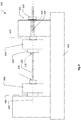
- FIG. 3 a schematic diagram is shown illustrating part of an exemplary cold spray device 300 comprising a pre-chamber 302 into which cold spray particles and pressurised gas are fed, and a cold spray nozzle 310 coupled to the pre-chamber 302.
- the nozzle 310 shown in Figure 3 is in the form of a De Laval nozzle comprising a converging zone 312, a throat 314 and a diverging zone 316.
- the nozzle 310 is configured such that the pressurised gas and cold spray particles are accelerated as they flow from the pre-chamber 302 through the nozzle 310 and are then propelled or sprayed generally along a central spray axis 320 to impinge on a surface of a substrate 330, such as a workpiece 100. At least some of the cold spray particles are accelerated to a velocity at which they undergo plastic deformation on impacting the surface and bond to the surface forming a deposition layer on the surface.
- the apparatus 400 comprises: a frame 402; a first spindle 404 rotatably coupled to the frame 402; a first coupler 406 configured to couple the first spindle 404 to a first end 106 of the workpiece 100; a second spindle 414 rotatably coupled to the frame 402; and a second coupler 416 configured to couple the second spindle 414 to a second end 116 of the workpiece 100.
- the spindles 404, 414 may each comprise one or more components, such as a drive shaft, a chuck and/or one or more bearings, for example.
- the spindles 404, 414 may be directly or indirectly coupled to the frame 402, and may be coupled to the frame 402 via one or more other components or mechanisms.
- the spindles 404, 414 may generally be limited to one degree of rotational freedom relative to the frame 402 about a common axis of rotation, but may also be configured for axial and/or lateral position adjustment in some embodiments.
- the couplers 406, 416 may each comprise one or more components, such as flexible couplers, for example.
- the couplers 406, 416 may be directly or indirectly coupled to the frame spindles 404, 414 and may be coupled to the spindles 404, 414 or the workpiece via one or more other components or mechanisms.
- the apparatus may comprise a tension meter 420 configured to measure the tension applied to the workpiece 100.
- the tension meter 420 may be disposed between any two components between the first and second spindles 404, 414, or in some embodiments, may be disposed on one of the components.
- the tension meter 420 may comprise a strain gauge fixed to a surface of one of the spindles 404, 414 or couplers 406, 416.
- the couplers 406, 416 may generally be limited to one degree of rotational freedom relative to the frame 402 about a common axis of rotation with the spindles, but may also be configured for axial and/or lateral position adjustment in some embodiments. For example, part of one or both couplers 406, 416 may be axially adjustable relative to the spindles 404, 414 to allow adjustment of the tension applied to the workpiece 100.
- couplers 406, 416 may comprise flexible couplers to allow for some degree of axial, rotational, lateral or angular deflection or movement of the workpiece 100 relative to the spindles 404, 414, to facilitate holding the workpiece under tension, to compensate for misalignments between the spindles 404, 414 or to reduce the effects of vibrations or sudden accelerations on the workpiece 100.
- a distance between the first and second couplers 406, 416 is adjustable to hold the workpiece 100 under tension between the couplers 406, 416 while the one or more operations are performed. That is, the couplers 406, 416 are configured to hold the ends 1 06, 116 of the workpiece 100 (once mounted) and apply opposing forces to the workpiece 100 in opposing directions away from one another.
- the workpiece 100 can be rotated with the couplers 406, 416 relative to the frame 402 about a common axis of rotation 440 extending between the couplers 406, 416.
- the apparatus 400 may comprise a tension adjustment actuator 422 configured to adjust the tension applied to the workpiece 100 by adjusting the distance between the first and second couplers 406, 416.
- the tension adjustment actuator 422 shown in Figure 4 comprises a threaded rod 424 coupled to the second spindle 414 via a bearing 426 to allow rotation of the spindle 414 relative to the threaded rod 424.
- the threaded rod 424 is threadedly engaged with a threaded hand wheel 428 which abuts part of the frame 402, such that turning the hand wheel 428 adjusts an axial position of the threaded rod 424 together with the second spindle 414 relative to the first spindle 404 and the frame 402, thereby adjusting the distance between the couplers 406, 416 and the tension applied to the workpiece 100.
- one of the spindles 404, 414 such as the first spindle 404 may be driven by a motor 708 ( Figure 7A ) while the other one of the spindles 404, 414 such as the second spindle 414, may be free to rotate with the couplers 406, 416, workpiece 100 and first spindle 404.
- This arrangement may be suitable for relatively stronger workpieces 100 and/or low angular accelerations. However, for particularly delicate workpieces 100 and/or higher angular accelerations, the rotational inertia and changes in angular momentum of the second spindle 414 and second coupler 416 may break or damage the workpiece 100.
- the first and second spindles 404, 414 may be configured for co-rotation with each other. That is, any rotation of the spindles 404, 414 may be controlled to be simultaneous. This may be achieved by mechanically coupling the spindles 404, 414 to each other independently of the workpiece 100, such as via a parallel shaft and gear system, for example. In such examples, rotation of the first motor 708 may also cause rotation of the second spindle 414.
- the apparatus 400 further comprises a second motor 718 ( Figure 7A ) configured to rotate the second spindle 414.
- the two motors 708, 718 are configured to drive rotation of the spindles 404, 414 independently, and are controlled to cause synchronous co-rotation of the spindles 404, 414, i.e., with any rotations of the spindles 404, 414 occurring substantially simultaneously and with substantially equal angular positions, rates and accelerations.
- the apparatus 400 may further comprise a backing plate 500 disposed on one side of the workpiece 100 and configured to assist in supporting the workpiece 100 during cold spraying.
- a backing plate 500 is shown according to some embodiments.
- the backing plate 500 may be arranged behind the workpiece 100 relative to a cold spray nozzle 310, as shown in Figure 6 , to reduce the aerodynamic forces placed on the workpiece 100 by reducing the low pressure region in the wake of the workpiece 100.
- the backing plate 500 and workpiece 100 may be arranged with a small gap therebetween. In cases where the workpiece 100 flexes a small amount due to the cold spraying forces, part of the workpiece 100 may contact and be further supported by the backing plate 500.
- the workpiece 100 may be arranged to be in contact with the backing plate 100 along at least part of the length of the workpiece 100 in order to provide further support.
- the backing plate 500 may define a concave surface 502 configured to at least partially surround one side of the workpiece 100. This arrangement may provide further support and stability to the workpiece 100 to mitigate against deflections of the workpiece 100 due to aerodynamic oscillations or a misalignment between the central spray axis 320 and the axis of rotation 440 of the workpiece 100.
- the surface 502 may be polished or coated with a non-stick film to reduce friction between the backing plate 500 and the workpiece 100 when in contact.
- the backing plate 500 shown in the drawings is particularly suited for elongate workpieces 100, but may define a different geometry for differently shaped workpieces 100.
- the workpiece 100 is shown as a 3D printed part, but could comprise any workpiece 100 to be cold sprayed as discussed above.
- the cold spraying process may comprise moving the cold spray nozzle 310 at least along one side of the workpiece 100 in a direction 600 which is substantially parallel to the axis of rotation 440 of the workpiece 100.
- the traverse speed of the nozzle 310 may be different for different applications, and could be in the range of about 0.5 mm/s to 1000 mm/s, for example.
- the nozzle may typically be oriented with the central spray axis 320 substantially perpendicular to the axis of rotation 440 of the workpiece 100, but it may not be in some embodiments.
- a standoff distance between the nozzle 310 and the workpiece may be in the range of about 1 mm to 2.00mm, for example about 15mm to 100mm, and may be adjustable in some embodiments.
- the workpiece 100 may be rotated to a selected angle, cold sprayed at that angle, rotated to a new selected angle, and cold sprayed again. This process may be repeated for a number of different selected angles as required to provide the desired coverage of the coating on the workpiece 100.
- the workpiece 100 may be rotated continuously while the cold spray nozzle 310 is moved along the workpiece 100 in the direction 600 shown in Figure 6 while cold spraying the workpiece 100.
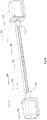
- FIG. 7A to 7C an apparatus 700 for holding a workpiece 100 under tension while one or more operations are performed on the workpiece 700, is shown, according to some embodiments. Similar components are indicated with similar reference numerals and may include similar features, as described in relation to Figure 4 .
- the apparatus 700 comprises: a frame 702 (see Figure 7C ); a first spindle 704 rotatably coupled to the frame 702; a first coupler 706 configured to couple the first spindle 704 to a first end 106 of the workpiece 100; a second spindle 714 rotatably coupled to the frame 702; and a second coupler 716 configured to couple the second spindle 714 to a second end 116 of the workpiece 100.
- the apparatus 700 further comprises a first motor 708 configured to rotate the first spindle 704 and a second motor 718 configured to rotate the second spindle 714.
- the motors 708, 718 may comprise stepper motors to allow the workpiece 100 to be rotated to a particular selected angle.
- the spindles 704, 714 comprise the drive shafts of the motors 708, 718.
- the spindles 704, 714 may be separate from and mechanically coupled to the drive shafts of the motors 708, 718.
- the motors 708, 718 may be configured for synchronous operation to affect co-rotation of the spindles 704, 714 as discussed above.
- a distance between the first and second couplers 706, 716 is adjustable to hold the workpiece 100 under tension between the couplers 706, 716 while the one or more operations are performed, and the workpiece 100 can be rotated with the couplers 706, 716 relative to the frame 702 about a common axis of rotation extending between the couplers 706, 716.
- the apparatus 700 may comprise a tension adjustment actuator 1222 ( Figure 12 ) configured to adjust the tension applied to the workpiece 100 by adjusting the distance between the first and second couplers 706, 716.
- the tension adjustment actuator 1222 may be configured to adjust an axial position of one of the couplers 706, 716 with respect to the spindles 704, 714; or to adjust an axial position of one of the spindles 704, 714 with respect to the motors 708, 718; or to adjust an axial position of one of the motors 708, 718 with respect to the frame 702.
- the frame 702 may comprise a track 703 allowing the position of one or both motors 708, 718 to be adjusted along the track for workpieces 100 of different lengths. Tension may be applied to the workpiece 100 by mounting the workpiece 100 in the apparatus 700 and then adjusting the position of one or both motors 708, 718 away from each other along the track 703.
- the tension adjustment actuator 1222 may comprise a third motor (not shown) configured to drive an adjustment mechanism such as a power screw threadedly engaged with part of a housing of one of the motors 708, 718, for example.
- the couplers 706, 716 may comprise any suitable coupling mechanisms for coupling the spindles 704, 714 to the respective ends 106, 116 of the workpiece 1 00.
- each coupler 706, 716 may define one or more bores configured to receive the corresponding spindle 704, 714 and/or the corresponding end 106, 116 of the workpiece 100, and comprise one or more grub screws configured to secure the spindle 704, 714 and/or workpiece 100 in the one or more bores.
- the couplers 706, 716 may comprise other clamping mechanisms, such as a chuck, for example.
- each of the couplers 706, 716 may comprise one or more components which cooperate to couple the workpiece 100 to the spindles 704, 714.
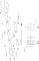
- the coupler 706 shown in Figure 10 comprises a flexible spring coupler 706a coupled to the spindle 704, and a split rod 706b configured to couple the workpiece 100 to the flexible coupler 706a.
- Different couplers 706, 716 may be used for different workpieces 100.
- some workpieces 100 may be formed with cylindrical ends 106, 116 (e.g. Figure 1 ) which may be received in cylindrical bores of the couplers 706, 716.
- Other workpieces 100 may be formed with flat plate ends 106, 116 (e.g. Figure 10 ) which may be received in a slot in the end of the coupler 706, 716 and fastened with clamping or another form of frictional engagement, such as by a grub screw, for example.
- the ends 106, 116 of the workpiece 100 may be configured to be held by the couplers, and subsequently removed from the workpiece 100 once the one or more operations are complete.
- a plurality of workpieces 100 may be mounted in the apparatus 700 together, coupled to each other end on end.
- the workpieces 100 may be joined to each other by a joiner coupler 726.
- the joiner coupler 726 may comprise a hollow sleeve with grub screws configured to clamp ends 106, 116 of adjacent workpieces 1 00 in the sleeve.
- the workpieces 100 themselves may be formed with ends 106, 116 configured to couple directly to each other.
- the workpieces 100 shown in Figure 8 define integrally formed joiner couplers 826 comprising complementary pegs and holes configured to mate with each other to couple adjacent workpieces 100 under tension.
- integral coupling portions There are a number of different integral coupling portions that may be suitable, and while the workpieces 100 shown are 3D printed workpieces 100, other types of workpieces 100 could be formed with integral complementary coupling portions.
- the ends 106, 116 of the workpiece 100 may be configured to be removed from the workpiece 100 once the one or more operations are complete.
- one or both of the couplers 706, 716 may be or comprise a flexible coupler such as a spring coupler to provide rotational flexibility between the workpiece 100 and one or both of the spindles 704, 714.
- the torsional stiffness of the or each flexible coupler may be in the range of about 10 N.m/rad to 500 N.m/rad, about 20 N.m/rad to 200 N.m/rad, or about 30 N.m/rad to 100 N.m/rad.
- Flexible couplers may also allow for some degree of axial, rotational, lateral or angular deflection of the workpiece 100 relative to the spindles 704, 714, for example to facilitate holding the workpiece under tension, to compensate for misalignments between the spindles 704, 714, or to reduce the effects of vibrations or sudden accelerations on the workpiece 100.
- any suitable flexible couplers may be used, such as the DR series of flexible couplers (e.g., model DR6.35X6.35-D18L25) supplied at oceancontrols.com.au or ibestchina.com, for example, and illustrated in Figures 9A and 9B .
- This type of coupler is defined by a hollow cylinder with a helical slot in the wall of the cylinder which forms a spring. There are bores at either end to receive the shaft of a spindle 704, 714, another coupling portion, or an end 106, 116 of the workpiece 100.
- the apparatus 700 may further comprise a cold spray device 300 which may be referred to as a cold spray gun, and a cold spray support frame (not shown) with a mechanism configured to move a nozzle 310 of the cold spray device 300 along an axis substantially parallel to the axis of rotation of the workpiece 100 to cold spray the workpiece 100 as shown in Figures 6 and 7B .
- the backing plate 500 may be fixed to the support frame on one side of the workpiece 100. After a certain amount of cold spraying, a cold spray deposition layer may build up on the backing plate 500, which may impede rotation of the workpiece 100. Therefore, it may be necessary to replace the backing plate 500 occasionally.
- the cold spray support frame mechanism may comprise one or more actuators to affect and control movement of the cold spray nozzle 310 in one, two or three spatial dimensions, such as parallel to the axis of rotation 440 of the workpiece 100, parallel to the central spray axis 320 of the cold spray nozzle 310, or in a lateral direction perpendicular to both the central spray axis 320 and the axis of rotation 440 of the workpiece 100.
- the one or more actuators may comprise one or more motors configured to adjust the position of the cold spray nozzle 310 along one or more tracks in the support frame.
- the apparatus 700 may further comprise one or more shielding plates 730 to shield one or more components of the apparatus 700 from cold spraying.
- the shielding plates 730 may be fixed to the frame 702.
- the shielding plates 730 may be held in one or more tracks in the frame 702 to allow the position of each shielding plate 730 to be adjusted to shield different components of the apparatus 700 or to move to a new shielding position when one of the components, such as a motor, is moved to a new position.
- Two shielding plates 730 are shown in Figure 7C shielding the motors 708, 718, couplers 706, 716 and spindles 704, 714. However, further shielding plates 730 may be included to shield any joining couplers 726 between adjacent workpieces 100 or other components which may require shielding.
- the apparatus 700 may further comprise a tension meter 1220 ( Figure 12 ) configured to measure the tension applied to the workpiece 100 as described in relation to apparatus 400.
- the tension adjustment actuator 1222 may be used to adjust the tension applied to the workpiece until a desired tension is achieved as observed using the tension meter 1220.
- FIG 10 part of an exemplary embodiment of the apparatus 700 is shown, with a flat plate end 104 of a 3D printed static mixer 100 mounted in a slot of a coupler 706.
- the coupler 706 comprises a the flexible coupler 706 illustrated in Figures 9A and 9B , and is configured to couple the end 104 of the workpiece 100 to a spindle 704 of a motor 708 mounted to a frame 702.
- the backing plate 500 is fixed to the frame 702 alongside the workpiece 100, and a shielding plate 730 is fixed to the frame in front of the motor 708.
- a motor control subsystem 1100 is shown according to some embodiments.
- the subsystem 1100 comprises the apparatus 700 described with reference to Figures 7A to 7C and a controller 1110 configured to control the rotation of the workpiece 100. This is achieved by controlling operation of the first and second motors 708, 718 by sending synchronised signals to first and second motor drivers 1108, 1118 respectively. In response to the synchronised signals, the first and second motor drivers 1108, 1118 regulate the supply of power to the motors 708, 718 to cause simultaneous co-rotation of the spindles 704, 714.
- the subsystem 1100 further comprises a power supply 1102, such as a 24 Volt DC power supply, to supply power to the controller 1110, motor drivers 1108, 1118 and motors 708, 718.
- the motors 708, 718 In embodiments where the motors 708, 718 are arranged in antiparallel, as shown in Figures 7A to 7C , the motors 708, 718 must be configured for counter-rotation in order to achieve co-rotation of the spindles 704, 714 in the same direction. This can be achieved by operating the controller 1110 to send equal and opposite signals to the motor drivers 1108, 1118 to effect equal and opposite rotation of the motors 708, 718, i.e., clockwise and counterclockwise, for example.
- the motor drivers 1108, 1118 may comprise digital drivers with a suitable sampling rate, such that any signal delays are rounded off to provide simultaneous signals to the motors 708, 718.
- suitable motor drivers include DM422 - 2 Phase Digital Stepper Drives, supplied by leadshine.com.
- An example of a suitable controller 1110 that can be used for controlling the motor drivers 1108, 1118 is the KTA-290 serial stepper motor controller supplied by oceancontrols.com.au.
- the subsystem 1100 may further comprise a serial interface 1120, including a serial cable, for example, to a computer 1240 ( Figure 12 ) to allow communication between the controller 1110 and the computer 1240.
- a serial interface 1120 including a serial cable, for example, to a computer 1240 ( Figure 12 ) to allow communication between the controller 1110 and the computer 1240.
- the controller 1110 and the computer 1240 may be configured to communicate via a suitable wireless communication protocol and each may include or employ suitable wireless communication subsystems for that purpose.
- a multifunction control system 1200 for holding a workpiece 100 under tension and controlling rotation of the workpiece 100 is shown, according to some embodiments.
- the system 1200 comprises the motor control subsystem 1100, a computer 1240 and an apparatus 400, 700 according to any one of the embodiments described herein; and a controller 1110 configured to control the rotation of the workpiece 100.
- the apparatus 400, 700 comprises a first motor 708 configured to cause rotation of the workpiece 100 in response to a control signal from the controller 1110.
- the control signal may be provided to the motor 708 (and re-encoded as appropriate) via a motor driver 1108 as described in relation to Figure 11 .
- the controller 1110 controls the motor 708 by regulating the supply of power to the motor 708 from the power supply 1102.
- the computer 1240 includes a computer processor 1242 configured to execute a control module 1244 stored on memory 1246 accessible to the processor 1242.
- the control module 1244 comprises executable program code that, when executed by the processor 1242, causes the processor 1242 to perform control functions in relation to apparatus 400, 700 as described herein.
- the control module 1244 is configured to provide control and monitoring functions in relation to performance of the cold spray process described herein.
- the control module 1244 (or another software application executable by processor 1242) is executable by the processor 1242 to provide a user interface to allow a user to provide input to be transmitted to the controller 1110 to control one or more operations of the apparatus 400, 700.
- the computer 1240 is communicatively coupled to the controller 1210, such as via a serial cable or a wireless connection, for example, to operate the controller 1110 via the user interface on the computer 1240.
- the apparatus 400,700 may comprise a single motor 708 configured to drive rotation of the workpiece 100 as described above in relation to apparatus 400.
- the apparatus 400, 700 may further comprise a second motor 718 configured as described in relation to apparatus 400 or 700 above, for example.
- the controller 1110 may be configured to control the first and second motors 708, 718 synchronously as described in relation to apparatus 700 above.
- the motors 708, 718 may be controlled via motor drivers 1108, 1118 as described in relation to subsystem 1100.
- controller 1110 may be further configured to control a tension adjustment actuator 1222, as described in relation to apparatus 700 above.
- the apparatus 400, 700 may comprise a tension meter 1220 configured as described in relation to apparatus 400 and 700 above.
- the controller 1110 may be configured to receive a measurement signal from the tension meter 1220 indicating the level of tension applied to the workpiece 100, and control the tension adjustment actuator 1222 to adjust the tension applied to the workpiece in a feedback loop until a selected tension is achieved.
- the controller 1110 may further be configured to control one, two or more cold spray positioning actuators 1230 to control movement of a cold spray nozzle 310 to cold spray the workpiece 100 as described in relation to apparatus 700 above.
- the apparatus 400, 700 may include three cold spray positioning actuators 1230a, 1230b and 1230c, each arranged to position the cold spray nozzle 310 in one of three different dimensions (i.e. X, Y and Z axes).
- the controller 1110 may be configured to control the actuators 1230 to control movement of the cold spray nozzle in one, two or three spatial dimensions, such as parallel to the axis of rotation of the workpiece, parallel to a central spray axis of the cold spray nozzle, or in a lateral direction perpendicular to both the central spray axis and the axis of rotation of the workpiece 100.
- the controller 1110 may further be configured to control operations of the cold spray device 300.
- the described apparatuses, systems and processes may be useful for supporting a number of different types of workpieces while one or more operations are performed on the workpiece.
- the workpiece is a static mixer.
- the static mixer may be additive manufactured or 3D printed.
- the static mixer may be an integral element for a chemical reactor chamber, for example a continuous flow chemical reactor chamber.
- the static mixer may comprise a catalytically active scaffold defining a plurality of passages configured for dispersing and mixing one or more fluidic reactants during flow and reaction thereof through the mixer.
- the static mixer may be configured as a modular insert for assembly into a continuous flow chemical reactor or chamber thereof.
- the static mixer element may be configured as an insert for an in-line continuous flow chemical reactor or chamber thereof.
- the workpiece for example an additive manufactured workpiece (e.g. static mixer), may not be particularly strong under compression, although may be relatively stronger under tension.
- the workpiece may be fragile or brittle, for example where a certain longitudinal compressive force may break, bend, deform, fracture or otherwise damage the workpiece. For example, some workpieces may be damaged by a longitudinal compressive force greater than about 5 N, about 10 N, about 50 N, or about 100 N.
- the static mixer element may be configured for enhancing mixing and heat transfer characteristics for redistributing fluid in directions transverse to the main flow, for example in radial and tangential or azimuthal directions relative to a central longitudinal axis of the static mixer element.
- the static mixer element may be configured for at least one of (i) to ensure as much catalytic surface area as possible is presented to the flow so as to activate close to a maximum number of reaction sites and (ii) to improve flow mixing so that (a) the reactant molecules contact surfaces of the static mixer element more frequently and (b) heat is transferred away from or to the fluid efficiently.
- the static mixer element may be provided with various geometric configurations or aspect ratios for correlation with particular applications.
- the static mixer elements enable fluidic reactants to be mixed and brought into close proximity with the catalytic material for activation.
- the static mixer element may be configured for use with turbulent flow rates, for example enhancing turbulence and mixing, even at or near the internal surface of the reactor chamber housing.
- the configurations may also be designed to enhance efficiency, degree of chemical reaction, or other properties such as pressure drop (whilst retaining predetermined or desired flow rates), residence time distribution or heat transfer coefficients.
- the workpiece may be a static mixer element, scaffold, or reactor chamber thereof.
- Additive manufacturing of the static mixer and subsequent catalytic coating can provide a static mixer that is configured for efficient mixing, heat transfer and catalytic reaction (of reactants in continuous flow chemical reactors), and in which the static mixer may be physically tested for reliability and performance, and optionally further re-designed and reconfigured using additive manufacturing (e.g. 3D printing) technology.
- Additive manufacturing provides flexibility in preliminary design and testing, and further re-design and re-configuration of the static mixers to facilitate development of more commercially viable and durable static mixers.
- the static mixer element may be provided in a configuration selected from one or more of the following general non-limiting example configurations:
- the static mixer may be provided in a mesh configuration having a plurality of integral units defining a plurality of passages configured for facilitating mixing of the one or more fluidic reactants.
- the static mixer element may comprise a scaffold provided by a lattice of interconnected segments configured to define a plurality of apertures for promoting mixing of fluid flowing through the reactor chamber.
- the scaffold may also be configured to promote both heat transfer as well as fluid mixing.
- the geometry or configuration may be chosen to enhance one or more characteristics of the static mixer element selected from: the specific surface area, volume displacement ratio, line-of-sight accessibility for cold-spraying, strength and stability for high flow rates, suitability for fabrication using additive manufacturing, and to achieve one or more of: a high degree of chaotic advection, turbulent mixing, catalytic interactions, and heat transfer.
- the workpiece may be configured to enhance chaotic advection or turbulent mixing, for example cross-sectional, transverse (to the flow) or localised turbulent mixing.
- the geometry of the workpiece may be configured to change the localised flow direction or to split the flow more than a certain number of times within a given length along a longitudinal axis of the static mixer element, such as more than 200 m -1 , more than 400 m -1 ., more than 800 m -1 , more than 1500 m -1 , more than 2000 m -1 , more than 2500 m - 1 , more than 3000 m -1 , or more than 5000 m -1 .
- the geometry or configuration may comprise more than a certain number of flow splitting structures within a given volume of the static mixer, such as more than 100 m -3 , more than 1000 m -3 , more than 1x10 4 m -3 , more than 1x10 6 m -3 , more than 1x10 9 m -3 , or more than 1x10 10 m -3 .
- the geometry or configuration of the workpiece may be substantially tubular or rectilinear.
- the workpiece may be formed from or comprise a plurality of segments. Some or all of the segments may be straight segments. Some or all of the segments may comprise polygonal prisms such as rectangular prisms, for example.
- the workpiece may comprise a plurality of planar surfaces.
- the straight segments may be angled relative to each other. Straight segments may be arranged at a number of different angles relative to a longitudinal axis of the scaffold, such as two, three, four, five or six different angles, for example.
- the workpiece may comprise a repeated structure.
- the workpiece may comprise a plurality of similar structures repeated periodically along the longitudinal axis of the scaffold.
- the geometry or configuration of the scaffold may be consistent along the length of the scaffold.
- the geometry of the scaffold may vary along the length of the scaffold.
- the straight segments may be connected by one or more curved segments.
- the scaffold may comprise one or more helical segments.
- the scaffold may generally define a helicoid.
- the scaffold may comprise a helicoid including a plurality of apertures in a surface of the helicoid.
- the dimensions of the workpiece may be varied depending on the application.
- the static mixer, or reactor comprising the static mixer may be tubular.
- the workpiece may, for example, have a diameter (in mm) in the range of 1 to 5000, 2 to 2500, 3 to 1000, 4 to 500, 5 to 150, or 10 to 100.
- the workpiece may, for example, have a diameter (in mm) of at least about 1, 5, 10. 25, 50, 75, 100, 250, 500, or 1000.
- the workpiece may, for example, have a diameter (in mm) of less than about 5000, 2500, 1000, 750, 500, 250, 200, 150, 100, 75, or 50.
- the aspect ratios (L/d) of the workpiece may be provided in a range suitable for industrial scale flow rates for a particular reaction.
- the aspect ratios may, for example, be in the range of about 1 to 1000, 2 to 750, 3 to 500, 4 to 250, 5 to 100, or 10 to 50.
- the aspect ratios may, for example, be less than about 1000, 750, 500, 250, 200, 150, 100, 75, 50, 25, 20, 15, 10, 9, 8, 7, 6, 5, 4, 3, or 2.
- the aspect ratios may, for example, be greater than about 1, 2, 3, 4, 5, 6, 7, 8, 9, 10, 15, 20, 25, 50, 75, or 100.
- the workpiece may be generally provided with a high specific surface area.
- the specific surface area (m 2 m -3 ) may be in the range of 100 to 40,000, 200 to 30,000, 300 to 20,000, 500 to 15,000, or 12000 to 10,000.
- the specific surface area (m 2 m -3 ) may be at least 100, 200, 300, 400, 500, 750, 1000, 2000, 3000, 4000, 5000, 7500, 10000, 12500, 15000, 17500, or 20000. It will be appreciated that the specific surface areas can be measured by a number of techniques including the BET isotherm techniques.
- the workpiece may be configured for enhancing properties, such as mixing and heat transfer, for laminar flow rates or turbulent flow rates.
- properties such as mixing and heat transfer
- the static mixer elements may be configured for laminar or turbulent flow rates to provide enhanced properties selected from one or more of mixing, degree of reaction, heat transfer, and pressure drop. It will be appreciated that further enhancing a particular type of chemical reaction will require its own specific considerations.
- the static mixer element may be generally configured for operating at a Re of at least 0.01, 0.1, 1, 5, 50, 100, 150, 200, 250, 300, 350, 400, 550, 600, 650,700,750,800,850,900,950,1000,1100,1200,1300,1400,1500,1600,1700,1800, 1900, 2000, 2500, 3000, 3500, 4000, 4500, 5000, 5500, 6000, 6500, 7000, 7500, 8000, 8500, 9000, 9500, 10000.
- the static mixer element may be configured for operating in a generally laminar flow Re range of about 0.1 to 2000, 1 to 1000, 10 to 800, or 20 to 500.
- the static mixer element may be configured for operating in a generally turbulent flow Re ranges of about 1000 to 15000, 1500 to 10000, 2000 to 8000, or 2500 to 6000.
- the volume displacement % of the static mixer relative to a reactor chamber for containing the mixer is in the range of 1 to 40, 2 to 35, 3 to 30, 4 to 25, 5 to 20, or 10 to 15.
- the volume displacement % of the static mixer relative to a reactor chamber for containing the mixer may be less than 40%, 35%, 30%, 25%, 20%, 15%, 10%, or 5%.
- the configurations of the static mixers may be provided to enhance cross-sectional microscopic turbulence.
- the turbulent length scales may, for example, be in the range of microscopic length scales.
- the configurations of the static mixers may be provided to enhance heat transfer properties in the reactor, for example a reduced temperature differential at the exit cross-section.
- the static mixer may be configured such that, in use, the pressure drop (i.e. pressure differential or back pressure) across the static mixer (in Pa/m) is in a range of about 0.1 to 1,000,000 Pa/m (or 1 MPa/m).
- the static mixers may be configured to provide a lower pressure drop relative to a specific flow rate.
- the static mixers, reactor, system, and processes, as described herein may be provided with parameters suitable for industrial application.
- the above pressure drops may be maintained where the volumetric flow rate is at least 0.1, 0.5, 1, 1.5, 2, 2.5, 3, 3.5, 4, 4.5, 5, 6, 7, 8, 9, 10, 20, 30, 40, 50 ml/min.
- the workpiece for example the static mixer, may be made by the additive manufacture (i.e. 3D printing) techniques.
- 3D printing i.e. 3D printing
- an electron beam 3D printer or a laser beam 3D printer may be used.
- the additive material for the 3D printing may be, for example, titanium alloy based powders (e.g. 45-105 micrometre diameter range) or the cobalt-chrome alloy based powders (e.g. FSX-414) or stainless steel or aluminium-silicon alloy.
- the powder diameters associated with the laser beam printers are typically lower than those used with electron beam printers.
- 3D printing is well understood and refers to processes that sequentially deposit material onto a powder bed via fusion facilitated by the heat supplied by a beam, or by extrusion and sintering-based processes.
- 3D printable models are typically created with a computer aided design (CAD) package.
- CAD computer aided design
- STL file Before printing a 3D model from an STL file, it is typically examined for manifold errors and corrections applied. Once that is done, the .STL file is processed by software called a "slicer,” which converts the model into a series of thin layers and produces a G-code file containing instructions tailored to a specific type of 3D printer.
- the 3D printing process is advantageous for use in preparing the static mixer elements since it eliminates the restrictions to product design imposed by traditional manufacturing routes. Consequently, the design freedom inherited from 3D printing allows a static mixer geometry to be further optimised for performance than it otherwise would have been.
- the workpiece e.g. static mixer or scaffold thereof
- the workpiece may be formed from a catalytic material.
- a catalyst material may be intercalated, interspersed and/or embedded with at least part of the scaffold.
- the catalyst material of the scaffold or cold spray coating on the scaffold may be selected and varied based on a particular reaction or application required.
- the catalyst material may be selected to provide for heterogeneous catalysis reactions in a continuous flow reactor environment.
- a wide range of heterogeneous catalysis chemical reactions may be provided for by selection from a wide range of catalytic materials, including but not limited to the following: hydrogenations using hydrogen gas, transfer hydrogenations using a liquid hydrogen donor, catalytic oxidations, reductive animations, carbon-carbon couplings including Suzuki, Sonogashira, Heck, Stille, Negishi, Ullmann, Kumada couplings and other metal catalysed organic transformations.
- the workpiece or scaffold of the static mixer may comprise or consist of at least one of a metal, metal alloy, cermet and metal oxide.
- the scaffold may be a metal scaffold, for example formed from metals or metal alloys.
- the scaffold may be formed from a metal or metal alloy capable of catalytic reactions, such as palladium.
- the metal scaffold may be prepared from a material suitable for additive manufacturing (i.e. 3D printing).
- the metal scaffold may be prepared from a material suitable for further surface modification to provide or enhance catalytic reactivity, for example a metal including nickel, titanium, palladium, platinum, gold, copper, aluminium or their alloys and others, including metal alloys such as stainless steel.
- the metal for the scaffold may comprise or consist of titanium, stainless steel, and an alloy of cobalt and chromium. In another embodiment, the metal for the scaffold may comprise or consist of stainless steel and cobalt chromium alloy.
- the metal scaffold can be specifically designed to perform two major tasks: a) to act as a catalytic layer or a substrate for a catalytic layer, b) to act as a flow guide for optimal mixing performance during the chemical reaction and subsequently assist transfer of exothermic heat to the walls of the reactor tube (single phase liquid stream or multiphase stream) inside the reactor.
- the catalytic material for forming the workpiece or for cold spray coating of the workpiece may comprise or consist of a metal selected from at least one of iron, aluminium, cobalt, copper, zinc, nickel, palladium, platinum, gold, silver, ruthenium, iridium, rhodium, titanium vanadium, zirconium, niobium, tantalum, and chromium, or a metal alloy, cermet or metal oxide thereof.
- the catalytic material may comprise or consist of titanium, aluminium, nickel, iron, silver, cobalt, chromium, or an alloy thereof.
- the catalytic material may comprise or consist of titanium, titanium alloy or stainless steel.
- the titanium alloy may comprise aluminium and vanadium, for example.
- Non-limiting examples of other transition metals that may be used in metal alloys are zirconium, niobium and tantalum.
- the catalytic material for forming the workpiece or for cold spray coating of the workpiece may comprise at least one of a metal, semi-metal and metal oxide.
- the catalytic material may comprise one or more of the following:
- a catalytic material may refer to a catalyst by itself or to a material or composition comprising a catalyst.
- the catalytic material may be provided in a composition with one or more additives, such as binders, to facilitate coating of the catalyst to the workpiece.
- the catalyst or coating thereof may be provided as a partial coating or a complete layer on the workpiece.
- the additives may include catalysts or promoters to enhance reaction rates at the static mixer surface.
- the catalyst material may include a dissociation catalyst, which may be chosen from the group consisting of molybdenum, tungsten, iron, ruthenium, cobalt, boron, chromium, tantalum, nickel, and alloys, compounds and mixtures thereof.
- the workpiece e.g. static mixer
- the workpiece comprises or consists of titanium, nickel, aluminium, stainless steel, cobalt, chromium, any alloy thereof, or any combination thereof.
- the workpiece e.g. static mixer
- the cold spray coating may comprise a metal selected from platinum or nickel.
- the weight % of the coating, based on total weight of the workpiece (e.g. static mixer), may be in the range of 1 to 40%, 2 to 35%, 5 to 30%, 10 to 25 %, or 15 to 20%.
Description
- The present application claims priority from Australian Provisional Patent Application No
2015905354 filed on 23 December 2015 2016903998 filed on 3 October 2016 - The present disclosure relates to apparatuses and systems for holding a workpiece while one or more operations are performed on the workpiece, as well as processes involving holding a workpiece while one or more operations are performed on the workpiece. The embodiments described herein may be particularly suited to holding brittle, delicate or fragile workpieces during cold spraying processes, for example.
- When performing operations on elongate workpieces that are rotated during performance of the operations, the workpiece is typically mounted or held between two points under compression in a device such as a lathe, for example. The workpiece may be clamped at one or both ends to rotatable couplers such as chucks which hold the workpiece firmly in position while allowing for, or in some cases driving, rotation of the workpiece with the couplers.
- However, in some cases, the compressive force required to hold the workpiece in position may break, bend, buckle or otherwise damage the workpiece.
- It is desired to address or ameliorate one or more shortcomings or disadvantages associated with existing apparatuses and systems for holding a workpiece, or to at least provide a useful alternative thereto.
- Any discussion of documents, acts, materials, devices, articles or the like which has been included in the present specification is not to be taken as an admission that any or all of these matters form part of the prior art base or were common general knowledge in the field relevant to the present disclosure as it existed before the priority date of each claim of this application.
-
FR2770156 - The invention relates to an apparatus for holding a workpiece under tension while the workpiece is coated using a cold spraying process according to
claim 1. - In some embodiments, the apparatus may further comprise a tension adjustment actuator configured to adjust the tension applied to the workpiece by adjusting the distance between the first and second couplers. The tension applied to the workpiece will vary between applications, and may be in the range of about 10 N to 500 N, about 20 N to 300 N, about 30 N to 300 N, about 50 N to 200 N, or about 60 N to 100 N.
- In some embodiments, one or both of the couplers may comprise a flexible coupler, such as a spring coupler, for example, to provide rotational flexibility between the workpiece and one or both of the spindles. The torsional stiffness of the or each flexible coupler may be in the range of about 10 N.m/rad to 500 N.m/rad, about 20 N.m/rad to 200 N.m/rad, or about 30 N.m/rad to 100 N.m/rad. In some embodiments, one or both of the couplers may comprise a flexible coupler, such as a spring coupler, for example, to provide longitudinal or axial flexibility between the workpiece and one or both of the spindles. The axial stiffness of the or each flexible coupler may be in the range of about 0.01 N/m to 1 N/m, about 0.05 N/m to 0.5 N/m, about 0.05 N/m to 0.25 N/m, or about 0.05 N/m to 0.15 N/m.
- The couplers may be configured to support the workpiece while it is coated using a cold spraying process. The apparatus may further comprise a backing plate disposed on one side of the workpiece and configured to assist in supporting the workpiece during cold spraying. The backing plate may define a concave surface configured to at least partially surround one side of the workpiece. For example, the concave surface may define a concave channel within which the workpiece extends and within which the workpiece is at least partially received when mounted for rotation. The apparatus, couplers and/or backing plate may be particularly configured to support elongate static mixer elements during cold spraying.
- In some embodiments, the apparatus may further comprise one or more shielding plates to shield one or more components of the apparatus from cold spraying.
- In some embodiments, the apparatus may further comprise a cold spray device and a cold spray support frame with a mechanism configured to move a nozzle of the cold spray device along an axis substantially parallel to the axis of rotation of the workpiece to cold spray the workpiece. A standoff distance between the cold spray nozzle and the workpiece may be adjustable. A lateral position of the cold spray nozzle may be adjustable in a direction perpendicular to the standoff distance and the axis of rotation of the workpiece. The cold spray support frame mechanism may comprise one or more actuators to affect and control movement of the cold spray nozzle in one, two or three spatial dimensions, such as parallel to the axis of rotation of the workpiece, parallel to a central spray axis of the cold spray nozzle, or in a lateral direction perpendicular to both the central spray axis and the axis of rotation of the workpiece.
- In some embodiments, the apparatus may further comprise a tension meter configured to measure the tension applied to the workpiece. The tension meter may be coupled to any one or more of the frame, spindles, and couplers, and may be configured to be directly coupled to the workpiece.
- The invention also relates to a system for holding a workpiece under tension and controlling rotation of the workpiece while the workpiece is coated using a cold spraying process, the system comprising: an apparatus according to any one of the embodiments described herein; and a controller configured to control the rotation of the workpiece.
- In some embodiments, the controller may be configured to control one or more motors to affect and control rotation of the workpiece. In some embodiments, the system may be configured for controlling cold spraying of the workpiece.
- In some embodiments, the controller may be further configured to control the tension adjustment actuator to adjust the tension applied to the workpiece. In some embodiments, the controller may be configured to control the tension adjustment actuator to adjust the tension applied to the workpiece to a selected tension, in response to receiving a signal from the tension meter, until the selected tension is achieved.
- In some embodiments, the controller may be further configured to control one or more actuators associated with the mechanism of the cold spray support frame to control movement of the cold spray nozzle relative to the workpiece. The controller may be configured to control the actuators to control movement of the cold spray nozzle in one, two or three spatial dimensions, such as parallel to the axis of rotation of the workpiece, parallel to a central spray axis of the cold spray nozzle, or in a lateral direction perpendicular to both the central spray axis and the axis of rotation of the workpiece.
- The system may further comprise a computer processor configured to execute software stored on memory accessible to the processor to provide a user interface to allow a user to provide input to be transmitted to the controller to control one or more operations of the apparatus.
- The invention also relates to a process according to claim 9, the process comprising: rotating a workpiece held under tension; and performing one or more operations on the workpiece.
- The process also comprises: mounting the workpiece between two couplers; adjusting a distance between the two couplers to apply tension to the workpiece; rotating the workpiece; and performing one or more operations on the workpiece while the workpiece is held between the two couplers under tension.
- Mounting the workpiece comprises mounting the workpiece in an apparatus according to and of
claims 1 to 6.. In some embodiments, the process may comprise using a system according to any one of the described embodiments to perform at least part of the process. - Rotating the workpiece may comprise rotating the workpiece to a selected angle and subsequently performing one or more operations on the workpiece, or rotating the workpiece continuously while performing one or more operations on the workpiece. The rate of rotation of the workpiece may be varied for different applications, and may be in the range of about 1 rpm to about 2000 rpm, about 10 rpm to about 1000 rpm, or about 50 rpm to about 500 rpm.
- In some embodiments, the process may further comprise progressively ramping up the rate of rotation of the workpiece to a selected continuous rotation rate. The magnitude of angular acceleration of the workpiece may be kept below a particular value of angular acceleration to avoid applying excessive torsional forces to the workpiece. For example, the magnitude of angular acceleration of the workpiece may be kept below about 300 rad.s-2, below about 100 rad.s-2, below about 50 rad.s-2, below about 10 rad.s-2, below about 5 rad.s-2, below about 1 rad.s-2, or below about 0.1 rad.s-2. In some embodiments, the magnitude of angular acceleration of the workpiece may be kept within a range of about 0.05 rad.s-2 to 25 rad.s-2, for example.
- In some embodiments, there may be removable end portions at each end of the workpiece to be held by the couplers. In some embodiments, the workpiece may comprise a plurality of workpiece elements (each of which may be considered to be a workpiece in its own right) coupled together end to end by joiner couplers. The joiner couplers may be
- In some embodiments, there may be removable end portions at each end of the workpiece to be held by the couplers. In some embodiments, the workpiece may comprise a plurality of workpiece elements (each of which may be considered to be a workpiece in its own right) coupled together end to end by joiner couplers. The joiner couplers may be integrally formed with the workpiece elements. The joiner couplers may be configured to be removable from the workpiece elements. For example, the joiner couplers may be separable from the workpiece elements at pre-formed points or areas of weakness.
- In some embodiments, the workpiece may comprise any one or more of: an elongate object, a delicate object, a fragile object, a brittle object, a 3D printed object, a porous object, a static mixer, or a series of concatenated static mixer elements joined end on end.
- In some embodiments, the one or more operations may comprise any one or more of: coating, painting, spray painting, surface treating, heat treating, polishing, sand blasting, or cold spraying.
- In some embodiments, the process may comprise cold spraying the workpiece using any one or more of: high pressure cold spraying, low pressure cold spraying, kinetic metallisation, pulsed gas dynamic spraying, and vacuum cold spraying.
- In some embodiments, the process may comprise cold spraying the workpiece with cold spray particles comprising at least one of a metal, metal alloy, cermet and metal oxide. For example, the cold spray particles may comprise a catalytic material selected from at least one of iron, aluminium, cobalt, copper, zinc, nickel, palladium, platinum, gold, silver, ruthenium, iridium, rhodium, titanium vanadium, zirconium, niobium, tantalum, and chromium, or a metal alloy, cermet or metal oxide thereof. In some embodiments, the cold spraying may be controlled to form a rough or porous deposition layer on a surface of the workpiece.
- In some embodiments, the process may comprise causing the workpiece to rotate while simultaneously causing a cold spray nozzle to move along an axis substantially parallel to an axis of rotation of the workpiece to coat at least part of the workpiece.
- Exemplary embodiments will now be described in detail with respect to the drawings, in which:
-
Figure 1 shows some examples of 3D printed static mixers; -
Figure 2 shows a further example of a 3D printed static mixer; -
Figure 3 is a schematic diagram of a cold spray nozzle and spray impinging on a surface of a substrate; -
Figure 4 is a schematic diagram of a workpiece mounted in an apparatus, according to some embodiments; -
Figure 5A is a perspective view of a backing plate, according to some embodiments; -
Figure 5B is a cross-sectional view of the backing plate ofFigure 5A ; -
Figure 6 is a perspective view of a cold spray nozzle, workpiece and backing plate illustrating a cold spraying arrangement, according to some embodiments; -
Figure 7A is a perspective view of a workpiece mounted in an apparatus, according to some embodiments; -
Figure 7B is a plan view of the workpiece and apparatus ofFigure 7A further illustrating a cold spraying arrangement according to some embodiments; -
Figure 7C is a perspective view of the cold spraying arrangement of 7B showing further features of the apparatus ofFigure 7A , according to some embodiments; -
Figure 8 is a perspective view of a plurality of workpiece elements joined together and mounted under tension between flexible couplers, according to some embodiments; -
Figure 9A is a side view of a flexible coupler, according to some embodiments; -
Figure 9B is an end view of the flexible coupler ofFigure 9A ; -
Figure 10 is a perspective view showing part of an apparatus with a static mixer mounted in the apparatus, according to some embodiments; -
Figure 11 is a block diagram showing a motor control subsystem, according to some embodiments; and -
Figure 12 is a block diagram showing a cold-spraying control system, according to some embodiments. - Embodiments generally relate to apparatuses and systems for holding a workpiece while one or more operations are performed on the workpiece, as well as processes involving holding a workpiece while one or more operations are performed on the workpiece. The embodiments described herein may be particularly suited to holding brittle, delicate or fragile workpieces during cold spraying processes, for example.
- As described in the related applications cross-referenced above, static mixers for continuous flow chemical reactors can be designed with complex geometries to promote mixing of one or more fluids. The advent of additive manufacturing and 3D printing has allowed for the design and manufacture of static mixers defining different geometries that may otherwise be difficult or impossible to produce. Some exemplary static mixers are shown in
Figures 1 and 2 and9 . - The cross-referenced applications also describe coating static mixers with a catalytic material to provide efficient catalytic reaction of reactants in continuous flow chemical reactors, and one method for applying such a coating is by cold spraying the catalytic material onto the surfaces of the static mixers.
- Cold spray coating techniques generally involve accelerating solid particles to supersonic velocities through a cold spray nozzle (see
Figure 3 ) to achieve ballistic impingement on the surface of a substrate such that the particles adhere to and coat the surface forming a deposition layer of material. Various metal powders may be used for cold spraying onto a surface, and there are a number of different types of cold spraying methods and systems including high pressure cold spray, low pressure cold spray, kinetic metallisation, pulsed gas dynamic spraying, and vacuum cold spray, for example. The particles and/or gas may or may not be preheated, but the temperature of the particles generally remains below the melting point of the particles. The particles may be accelerated to speeds in the range of 300 ms-1 to 1400 ms-1 and when they impinge on the surface, the particles plastically deform and bond to the surface. - The particles may be accelerated by feeding them through a converging-diverging nozzle with pressurised gas from a high pressure side of the nozzle to a low pressure side of the nozzle, thereby forming a supersonic gas jet with a stream of supersonic solid particles. In some cases, the solid particles may be fed into the gas jet on the low pressure side of the nozzle. The nozzle may be in the form of a de Laval nozzle as shown in
Figure 3 . - Cold spray techniques typically result in a dense layer of material forming on the surface of the substrate. However, if the cold spray conditions are carefully controlled a rough or porous coating suitable for catalysis can be formed on a suitable substrate such as a static mixer scaffold. The increased roughness may enhance micro-scale turbulent mixing of the fluidic reactants near the surface of the catalytic layer, and may provide a larger surface area of catalytic material on which catalytic reactions can occur. In some applications, it may be preferable to deposit the catalytic material on the scaffold in order to form a more porous catalytic layer, or a catalytic layer with increased roughness compared to that achieved using electro-deposition or other deposition techniques.
- One important consideration with cold spraying a surface is the significant force of the impinging jet of gas and spray particles on the object, against which the object must be sufficiently supported. Another important consideration is that there must be a direct line of sight from the cold spray nozzle to the surface, and the angular spread of effective cold spray adhesion is typically less than about 15° deviation from a central axis of the spray. Therefore, for complete coverage, most objects will need to be sprayed from multiple different angles by moving the cold spray nozzle to different positions and/or rotating the object itself.
- This could be done by fixedly mounting the object or workpiece in a clamp or holding jig, cold spraying one side of the workpiece, then dismounting the workpiece, remounting the workpiece in a different orientation to cold spray another side and repeating the process until the desired coating coverage is achieved. However, remounting a workpiece multiple times is very time consuming.
- Another possibility is to mount the workpiece between two couplers or chucks of a lathe to simplify the rotation of the workpiece or to allow for continuous rotation of the workpiece during cold spraying. Some workpieces may be held at one end only, in a single chuck, but others must be held at both ends to be sufficiently supported while operations are performed on them. Elongate workpieces are typically mounted in lathes under compression when such support is required. However, the compressive force required to support brittle, delicate or fragile workpieces against processing forces, such as the forces associated with cold spraying, may break, bend, deform, fracture or otherwise damage the workpiece.
- When performing operations such as cold spraying on fragile, brittle or delicate workpieces which are stronger in tension than in compression, this problem may be addressed by holding the workpiece in tension rather than applying a longitudinal compressive load to it.
- Furthermore, holding such a workpiece under tension in a way which allows for continuous or stepped rotation of the workpiece avoids the need for remounting the workpiece between cold spraying operations.
- Referring to
Figures 1 and 2 , a number ofexemplary workpieces 100 are shown. Theworkpieces 100 shown inFigures 1 and 2 are static mixers, which were produced using additive manufacturing or 3D printing. Due to their size and geometry, these static mixers are too delicate, and particularly too brittle, to be mounted in a conventional lathe under compression. - As discussed above, static mixers may be coated with a catalytic material to promote efficient catalytic reactions in a chemical flow reactor. One method for depositing a catalytic material on the surface of a static mixer is by cold spraying.
- Referring to
Figure 3 , a schematic diagram is shown illustrating part of an exemplarycold spray device 300 comprising a pre-chamber 302 into which cold spray particles and pressurised gas are fed, and acold spray nozzle 310 coupled to the pre-chamber 302. Thenozzle 310 shown inFigure 3 is in the form of a De Laval nozzle comprising a convergingzone 312, athroat 314 and a divergingzone 316. Thenozzle 310 is configured such that the pressurised gas and cold spray particles are accelerated as they flow from the pre-chamber 302 through thenozzle 310 and are then propelled or sprayed generally along acentral spray axis 320 to impinge on a surface of asubstrate 330, such as aworkpiece 100. At least some of the cold spray particles are accelerated to a velocity at which they undergo plastic deformation on impacting the surface and bond to the surface forming a deposition layer on the surface. - Referring to
Figure 4 , anapparatus 400 for holding aworkpiece 100 under tension while one or more operations are performed on theworkpiece 100, is shown, according to some embodiments. Theapparatus 400 comprises: aframe 402; afirst spindle 404 rotatably coupled to theframe 402; afirst coupler 406 configured to couple thefirst spindle 404 to afirst end 106 of theworkpiece 100; asecond spindle 414 rotatably coupled to theframe 402; and asecond coupler 416 configured to couple thesecond spindle 414 to asecond end 116 of theworkpiece 100. - The
spindles spindles frame 402, and may be coupled to theframe 402 via one or more other components or mechanisms. Thespindles frame 402 about a common axis of rotation, but may also be configured for axial and/or lateral position adjustment in some embodiments. - The
couplers couplers frame spindles spindles tension meter 420 configured to measure the tension applied to theworkpiece 100. Thetension meter 420 may be disposed between any two components between the first andsecond spindles tension meter 420 may comprise a strain gauge fixed to a surface of one of thespindles couplers - The
couplers frame 402 about a common axis of rotation with the spindles, but may also be configured for axial and/or lateral position adjustment in some embodiments. For example, part of one or bothcouplers spindles workpiece 100. In some embodiments,couplers workpiece 100 relative to thespindles spindles workpiece 100. - A distance between the first and
second couplers workpiece 100 under tension between thecouplers couplers ends 1 06, 116 of the workpiece 100 (once mounted) and apply opposing forces to theworkpiece 100 in opposing directions away from one another. Theworkpiece 100 can be rotated with thecouplers frame 402 about a common axis ofrotation 440 extending between thecouplers - The
apparatus 400 may comprise atension adjustment actuator 422 configured to adjust the tension applied to theworkpiece 100 by adjusting the distance between the first andsecond couplers tension adjustment actuator 422 shown inFigure 4 comprises a threadedrod 424 coupled to thesecond spindle 414 via abearing 426 to allow rotation of thespindle 414 relative to the threadedrod 424. The threadedrod 424 is threadedly engaged with a threadedhand wheel 428 which abuts part of theframe 402, such that turning thehand wheel 428 adjusts an axial position of the threadedrod 424 together with thesecond spindle 414 relative to thefirst spindle 404 and theframe 402, thereby adjusting the distance between thecouplers workpiece 100. - In some embodiments, one of the
spindles first spindle 404 may be driven by a motor 708 (Figure 7A ) while the other one of thespindles second spindle 414, may be free to rotate with thecouplers workpiece 100 andfirst spindle 404. This arrangement may be suitable for relativelystronger workpieces 100 and/or low angular accelerations. However, for particularlydelicate workpieces 100 and/or higher angular accelerations, the rotational inertia and changes in angular momentum of thesecond spindle 414 andsecond coupler 416 may break or damage theworkpiece 100. - In order to avoid this issue, in some unclaimed examples, the first and
second spindles spindles spindles workpiece 100, such as via a parallel shaft and gear system, for example. In such examples, rotation of thefirst motor 708 may also cause rotation of thesecond spindle 414. - In the invention, the
apparatus 400 further comprises a second motor 718 (Figure 7A ) configured to rotate thesecond spindle 414. The twomotors spindles spindles spindles - As discussed above, cold spraying involves high velocities and in some cases, the aerodynamic forces on the
workpiece 100 may be high enough to break, bend, deform, fracture or otherwise damage theworkpiece 100. Therefore, in some embodiments, theapparatus 400 may further comprise abacking plate 500 disposed on one side of theworkpiece 100 and configured to assist in supporting theworkpiece 100 during cold spraying. - Referring to
Figures 5A and 5B , abacking plate 500 is shown according to some embodiments. Thebacking plate 500 may be arranged behind theworkpiece 100 relative to acold spray nozzle 310, as shown inFigure 6 , to reduce the aerodynamic forces placed on theworkpiece 100 by reducing the low pressure region in the wake of theworkpiece 100. In some embodiments, thebacking plate 500 andworkpiece 100 may be arranged with a small gap therebetween. In cases where theworkpiece 100 flexes a small amount due to the cold spraying forces, part of theworkpiece 100 may contact and be further supported by thebacking plate 500. In some embodiments, theworkpiece 100 may be arranged to be in contact with thebacking plate 100 along at least part of the length of theworkpiece 100 in order to provide further support. - The
backing plate 500 may define aconcave surface 502 configured to at least partially surround one side of theworkpiece 100. This arrangement may provide further support and stability to theworkpiece 100 to mitigate against deflections of theworkpiece 100 due to aerodynamic oscillations or a misalignment between thecentral spray axis 320 and the axis ofrotation 440 of theworkpiece 100. Thesurface 502 may be polished or coated with a non-stick film to reduce friction between thebacking plate 500 and theworkpiece 100 when in contact. Thebacking plate 500 shown in the drawings is particularly suited forelongate workpieces 100, but may define a different geometry for differently shapedworkpieces 100. - Referring to
Figure 6 , an arrangement of thecold spray nozzle 310,workpiece 100 andbacking plate 500 is shown according to some embodiments. Theworkpiece 100 is shown as a 3D printed part, but could comprise anyworkpiece 100 to be cold sprayed as discussed above. The cold spraying process may comprise moving thecold spray nozzle 310 at least along one side of theworkpiece 100 in adirection 600 which is substantially parallel to the axis ofrotation 440 of theworkpiece 100. The traverse speed of thenozzle 310 may be different for different applications, and could be in the range of about 0.5 mm/s to 1000 mm/s, for example. - The nozzle may typically be oriented with the
central spray axis 320 substantially perpendicular to the axis ofrotation 440 of theworkpiece 100, but it may not be in some embodiments. A standoff distance between thenozzle 310 and the workpiece may be in the range of about 1 mm to 2.00mm, for example about 15mm to 100mm, and may be adjustable in some embodiments. - In some embodiments, the
workpiece 100 may be rotated to a selected angle, cold sprayed at that angle, rotated to a new selected angle, and cold sprayed again. This process may be repeated for a number of different selected angles as required to provide the desired coverage of the coating on theworkpiece 100. - In some embodiments, the
workpiece 100 may be rotated continuously while thecold spray nozzle 310 is moved along theworkpiece 100 in thedirection 600 shown inFigure 6 while cold spraying theworkpiece 100. - Referring to
Figures 7A to 7C , anapparatus 700 for holding aworkpiece 100 under tension while one or more operations are performed on theworkpiece 700, is shown, according to some embodiments. Similar components are indicated with similar reference numerals and may include similar features, as described in relation toFigure 4 . - The
apparatus 700 comprises: a frame 702 (seeFigure 7C ); afirst spindle 704 rotatably coupled to theframe 702; afirst coupler 706 configured to couple thefirst spindle 704 to afirst end 106 of theworkpiece 100; asecond spindle 714 rotatably coupled to theframe 702; and asecond coupler 716 configured to couple thesecond spindle 714 to asecond end 116 of theworkpiece 100. - The
apparatus 700 further comprises afirst motor 708 configured to rotate thefirst spindle 704 and asecond motor 718 configured to rotate thesecond spindle 714. Themotors workpiece 100 to be rotated to a particular selected angle. In theapparatus 700 shown inFigures 7A to 7C , thespindles motors spindles motors motors spindles - A distance between the first and
second couplers workpiece 100 under tension between thecouplers workpiece 100 can be rotated with thecouplers frame 702 about a common axis of rotation extending between thecouplers - The
apparatus 700 may comprise a tension adjustment actuator 1222 (Figure 12 ) configured to adjust the tension applied to theworkpiece 100 by adjusting the distance between the first andsecond couplers couplers spindles spindles motors motors frame 702. - The
frame 702 may comprise atrack 703 allowing the position of one or bothmotors workpieces 100 of different lengths. Tension may be applied to theworkpiece 100 by mounting theworkpiece 100 in theapparatus 700 and then adjusting the position of one or bothmotors track 703. The tension adjustment actuator 1222 may comprise a third motor (not shown) configured to drive an adjustment mechanism such as a power screw threadedly engaged with part of a housing of one of themotors - The
couplers spindles workpiece 1 00. For example, eachcoupler corresponding spindle corresponding end workpiece 100, and comprise one or more grub screws configured to secure thespindle workpiece 100 in the one or more bores. In other embodiments, thecouplers couplers workpiece 100 to thespindles coupler 706 shown inFigure 10 comprises aflexible spring coupler 706a coupled to thespindle 704, and asplit rod 706b configured to couple theworkpiece 100 to theflexible coupler 706a. -
Different couplers different workpieces 100. For example, someworkpieces 100 may be formed withcylindrical ends 106, 116 (e.g.Figure 1 ) which may be received in cylindrical bores of thecouplers Other workpieces 100 may be formed with flat plate ends 106, 116 (e.g.Figure 10 ) which may be received in a slot in the end of thecoupler ends workpiece 100 may be configured to be held by the couplers, and subsequently removed from theworkpiece 100 once the one or more operations are complete. - In some embodiments, a plurality of
workpieces 100 may be mounted in theapparatus 700 together, coupled to each other end on end. For example, theworkpieces 100 may be joined to each other by ajoiner coupler 726. Thejoiner coupler 726 may comprise a hollow sleeve with grub screws configured to clamp ends 106, 116 ofadjacent workpieces 1 00 in the sleeve. - In some embodiments, the
workpieces 100 themselves may be formed withends workpieces 100 shown inFigure 8 , define integrally formedjoiner couplers 826 comprising complementary pegs and holes configured to mate with each other to coupleadjacent workpieces 100 under tension. There are a number of different integral coupling portions that may be suitable, and while theworkpieces 100 shown are 3D printedworkpieces 100, other types ofworkpieces 100 could be formed with integral complementary coupling portions. In some embodiments, theends workpiece 100 may be configured to be removed from theworkpiece 100 once the one or more operations are complete. - In some embodiments, one or both of the
couplers workpiece 100 and one or both of thespindles workpiece 100 relative to thespindles spindles workpiece 100. - Any suitable flexible couplers may be used, such as the DR series of flexible couplers (e.g., model DR6.35X6.35-D18L25) supplied at oceancontrols.com.au or ibestchina.com, for example, and illustrated in
Figures 9A and 9B . This type of coupler is defined by a hollow cylinder with a helical slot in the wall of the cylinder which forms a spring. There are bores at either end to receive the shaft of aspindle end workpiece 100. - The
apparatus 700 may further comprise acold spray device 300 which may be referred to as a cold spray gun, and a cold spray support frame (not shown) with a mechanism configured to move anozzle 310 of thecold spray device 300 along an axis substantially parallel to the axis of rotation of theworkpiece 100 to cold spray theworkpiece 100 as shown inFigures 6 and7B . Thebacking plate 500 may be fixed to the support frame on one side of theworkpiece 100. After a certain amount of cold spraying, a cold spray deposition layer may build up on thebacking plate 500, which may impede rotation of theworkpiece 100. Therefore, it may be necessary to replace thebacking plate 500 occasionally. - The cold spray support frame mechanism may comprise one or more actuators to affect and control movement of the
cold spray nozzle 310 in one, two or three spatial dimensions, such as parallel to the axis ofrotation 440 of theworkpiece 100, parallel to thecentral spray axis 320 of thecold spray nozzle 310, or in a lateral direction perpendicular to both thecentral spray axis 320 and the axis ofrotation 440 of theworkpiece 100. For example, the one or more actuators may comprise one or more motors configured to adjust the position of thecold spray nozzle 310 along one or more tracks in the support frame. - In some embodiments, the
apparatus 700 may further comprise one ormore shielding plates 730 to shield one or more components of theapparatus 700 from cold spraying. The shieldingplates 730 may be fixed to theframe 702. In some embodiments, the shieldingplates 730 may be held in one or more tracks in theframe 702 to allow the position of each shieldingplate 730 to be adjusted to shield different components of theapparatus 700 or to move to a new shielding position when one of the components, such as a motor, is moved to a new position. Two shieldingplates 730 are shown inFigure 7C shielding themotors couplers spindles plates 730 may be included to shield any joiningcouplers 726 betweenadjacent workpieces 100 or other components which may require shielding. - In some embodiments, the
apparatus 700 may further comprise a tension meter 1220 (Figure 12 ) configured to measure the tension applied to theworkpiece 100 as described in relation toapparatus 400. The tension adjustment actuator 1222 may be used to adjust the tension applied to the workpiece until a desired tension is achieved as observed using thetension meter 1220. - Referring to
Figure 10 , part of an exemplary embodiment of theapparatus 700 is shown, with aflat plate end 104 of a 3D printedstatic mixer 100 mounted in a slot of acoupler 706. Thecoupler 706 comprises a theflexible coupler 706 illustrated inFigures 9A and 9B , and is configured to couple theend 104 of theworkpiece 100 to aspindle 704 of amotor 708 mounted to aframe 702. Thebacking plate 500 is fixed to theframe 702 alongside theworkpiece 100, and ashielding plate 730 is fixed to the frame in front of themotor 708. - Referring to
Figure 11 , amotor control subsystem 1100 is shown according to some embodiments. Thesubsystem 1100 comprises theapparatus 700 described with reference toFigures 7A to 7C and acontroller 1110 configured to control the rotation of theworkpiece 100. This is achieved by controlling operation of the first andsecond motors second motor drivers second motor drivers motors spindles subsystem 1100 further comprises apower supply 1102, such as a 24 Volt DC power supply, to supply power to thecontroller 1110,motor drivers motors - In embodiments where the
motors Figures 7A to 7C , themotors spindles controller 1110 to send equal and opposite signals to themotor drivers motors - In order to ensure that the co-rotation of the
spindles motors 708, 718), themotor drivers motors suitable controller 1110 that can be used for controlling themotor drivers - The
subsystem 1100 may further comprise aserial interface 1120, including a serial cable, for example, to a computer 1240 (Figure 12 ) to allow communication between thecontroller 1110 and thecomputer 1240. Alternatively, thecontroller 1110 and thecomputer 1240 may be configured to communicate via a suitable wireless communication protocol and each may include or employ suitable wireless communication subsystems for that purpose. - Referring to
Figure 12 , amultifunction control system 1200 for holding aworkpiece 100 under tension and controlling rotation of theworkpiece 100 is shown, according to some embodiments. Thesystem 1200 comprises themotor control subsystem 1100, acomputer 1240 and anapparatus controller 1110 configured to control the rotation of theworkpiece 100. - The
apparatus first motor 708 configured to cause rotation of theworkpiece 100 in response to a control signal from thecontroller 1110. The control signal may be provided to the motor 708 (and re-encoded as appropriate) via amotor driver 1108 as described in relation toFigure 11 . Thecontroller 1110 controls themotor 708 by regulating the supply of power to themotor 708 from thepower supply 1102. - The
computer 1240 includes acomputer processor 1242 configured to execute acontrol module 1244 stored onmemory 1246 accessible to theprocessor 1242. Thecontrol module 1244 comprises executable program code that, when executed by theprocessor 1242, causes theprocessor 1242 to perform control functions in relation toapparatus control module 1244 is configured to provide control and monitoring functions in relation to performance of the cold spray process described herein. The control module 1244 (or another software application executable by processor 1242) is executable by theprocessor 1242 to provide a user interface to allow a user to provide input to be transmitted to thecontroller 1110 to control one or more operations of theapparatus computer 1240 is communicatively coupled to the controller 1210, such as via a serial cable or a wireless connection, for example, to operate thecontroller 1110 via the user interface on thecomputer 1240. - In some embodiments, the apparatus 400,700 may comprise a
single motor 708 configured to drive rotation of theworkpiece 100 as described above in relation toapparatus 400. In some embodiments, theapparatus second motor 718 configured as described in relation toapparatus controller 1110 may be configured to control the first andsecond motors apparatus 700 above. Themotors motor drivers subsystem 1100. - In some embodiments, the
controller 1110 may be further configured to control a tension adjustment actuator 1222, as described in relation toapparatus 700 above. - In some embodiments, the
apparatus tension meter 1220 configured as described in relation toapparatus controller 1110 may be configured to receive a measurement signal from thetension meter 1220 indicating the level of tension applied to theworkpiece 100, and control the tension adjustment actuator 1222 to adjust the tension applied to the workpiece in a feedback loop until a selected tension is achieved. - In some embodiments, the
controller 1110 may further be configured to control one, two or more cold spray positioning actuators 1230 to control movement of acold spray nozzle 310 to cold spray theworkpiece 100 as described in relation toapparatus 700 above. For example, theapparatus spray positioning actuators cold spray nozzle 310 in one of three different dimensions (i.e. X, Y and Z axes). Thecontroller 1110 may be configured to control the actuators 1230 to control movement of the cold spray nozzle in one, two or three spatial dimensions, such as parallel to the axis of rotation of the workpiece, parallel to a central spray axis of the cold spray nozzle, or in a lateral direction perpendicular to both the central spray axis and the axis of rotation of theworkpiece 100. In some embodiments, thecontroller 1110 may further be configured to control operations of thecold spray device 300. - As described above, while the exemplary embodiments are focussed on cold spraying delicate elongate workpieces such as 3D printed static mixer elements, the described apparatuses, systems and processes may be useful for supporting a number of different types of workpieces while one or more operations are performed on the workpiece.
- In one particular embodiment, the workpiece is a static mixer. The static mixer may be additive manufactured or 3D printed. The static mixer may be an integral element for a chemical reactor chamber, for example a continuous flow chemical reactor chamber. The static mixer may comprise a catalytically active scaffold defining a plurality of passages configured for dispersing and mixing one or more fluidic reactants during flow and reaction thereof through the mixer. The static mixer may be configured as a modular insert for assembly into a continuous flow chemical reactor or chamber thereof. The static mixer element may be configured as an insert for an in-line continuous flow chemical reactor or chamber thereof.
- The workpiece, for example an additive manufactured workpiece (e.g. static mixer), may not be particularly strong under compression, although may be relatively stronger under tension. The workpiece may be fragile or brittle, for example where a certain longitudinal compressive force may break, bend, deform, fracture or otherwise damage the workpiece. For example, some workpieces may be damaged by a longitudinal compressive force greater than about 5 N, about 10 N, about 50 N, or about 100 N.
- The static mixer element may be configured for enhancing mixing and heat transfer characteristics for redistributing fluid in directions transverse to the main flow, for example in radial and tangential or azimuthal directions relative to a central longitudinal axis of the static mixer element. The static mixer element may be configured for at least one of (i) to ensure as much catalytic surface area as possible is presented to the flow so as to activate close to a maximum number of reaction sites and (ii) to improve flow mixing so that (a) the reactant molecules contact surfaces of the static mixer element more frequently and (b) heat is transferred away from or to the fluid efficiently. The static mixer element may be provided with various geometric configurations or aspect ratios for correlation with particular applications. The static mixer elements enable fluidic reactants to be mixed and brought into close proximity with the catalytic material for activation. The static mixer element may be configured for use with turbulent flow rates, for example enhancing turbulence and mixing, even at or near the internal surface of the reactor chamber housing. The configurations may also be designed to enhance efficiency, degree of chemical reaction, or other properties such as pressure drop (whilst retaining predetermined or desired flow rates), residence time distribution or heat transfer coefficients.
- The workpiece may be a static mixer element, scaffold, or reactor chamber thereof. Additive manufacturing of the static mixer and subsequent catalytic coating can provide a static mixer that is configured for efficient mixing, heat transfer and catalytic reaction (of reactants in continuous flow chemical reactors), and in which the static mixer may be physically tested for reliability and performance, and optionally further re-designed and reconfigured using additive manufacturing (e.g. 3D printing) technology. Additive manufacturing provides flexibility in preliminary design and testing, and further re-design and re-configuration of the static mixers to facilitate development of more commercially viable and durable static mixers.
- The static mixer element may be provided in a configuration selected from one or more of the following general non-limiting example configurations:
- open configurations with helices;
- open configurations with blades;
- corrugated-plates;
- multilayer designs;
- closed configurations with channels or holes.
- The static mixer may be provided in a mesh configuration having a plurality of integral units defining a plurality of passages configured for facilitating mixing of the one or more fluidic reactants. The static mixer element may comprise a scaffold provided by a lattice of interconnected segments configured to define a plurality of apertures for promoting mixing of fluid flowing through the reactor chamber. The scaffold may also be configured to promote both heat transfer as well as fluid mixing.
- In various embodiments, the geometry or configuration may be chosen to enhance one or more characteristics of the static mixer element selected from: the specific surface area, volume displacement ratio, line-of-sight accessibility for cold-spraying, strength and stability for high flow rates, suitability for fabrication using additive manufacturing, and to achieve one or more of: a high degree of chaotic advection, turbulent mixing, catalytic interactions, and heat transfer.
- The workpiece (e.g. static mixer) may be configured to enhance chaotic advection or turbulent mixing, for example cross-sectional, transverse (to the flow) or localised turbulent mixing. The geometry of the workpiece (e.g. static mixer) may be configured to change the localised flow direction or to split the flow more than a certain number of times within a given length along a longitudinal axis of the static mixer element, such as more than 200 m-1, more than 400 m-1., more than 800 m-1, more than 1500 m-1, more than 2000 m-1, more than 2500 m- 1, more than 3000 m-1, or more than 5000 m-1. The geometry or configuration may comprise more than a certain number of flow splitting structures within a given volume of the static mixer, such as more than 100 m-3, more than 1000 m-3, more than 1x10⁴ m-3, more than 1x10⁶ m-3, more than 1x10⁹ m-3, or more than 1x10¹⁰ m-3.
- The geometry or configuration of the workpiece (e.g. static mixer or scaffold thereof) may be substantially tubular or rectilinear. The workpiece may be formed from or comprise a plurality of segments. Some or all of the segments may be straight segments. Some or all of the segments may comprise polygonal prisms such as rectangular prisms, for example. The workpiece may comprise a plurality of planar surfaces. The straight segments may be angled relative to each other. Straight segments may be arranged at a number of different angles relative to a longitudinal axis of the scaffold, such as two, three, four, five or six different angles, for example. The workpiece may comprise a repeated structure. The workpiece may comprise a plurality of similar structures repeated periodically along the longitudinal axis of the scaffold. The geometry or configuration of the scaffold may be consistent along the length of the scaffold. The geometry of the scaffold may vary along the length of the scaffold. The straight segments may be connected by one or more curved segments. The scaffold may comprise one or more helical segments. The scaffold may generally define a helicoid. The scaffold may comprise a helicoid including a plurality of apertures in a surface of the helicoid.
- The dimensions of the workpiece (e.g. static mixer) may be varied depending on the application. The static mixer, or reactor comprising the static mixer, may be tubular. The workpiece may, for example, have a diameter (in mm) in the range of 1 to 5000, 2 to 2500, 3 to 1000, 4 to 500, 5 to 150, or 10 to 100. The workpiece may, for example, have a diameter (in mm) of at least about 1, 5, 10. 25, 50, 75, 100, 250, 500, or 1000. The workpiece may, for example, have a diameter (in mm) of less than about 5000, 2500, 1000, 750, 500, 250, 200, 150, 100, 75, or 50. The aspect ratios (L/d) of the workpiece may be provided in a range suitable for industrial scale flow rates for a particular reaction. The aspect ratios may, for example, be in the range of about 1 to 1000, 2 to 750, 3 to 500, 4 to 250, 5 to 100, or 10 to 50. The aspect ratios may, for example, be less than about 1000, 750, 500, 250, 200, 150, 100, 75, 50, 25, 20, 15, 10, 9, 8, 7, 6, 5, 4, 3, or 2. The aspect ratios may, for example, be greater than about 1, 2, 3, 4, 5, 6, 7, 8, 9, 10, 15, 20, 25, 50, 75, or 100.
- The workpiece may be generally provided with a high specific surface area. The specific surface area (m2 m-3) may be in the range of 100 to 40,000, 200 to 30,000, 300 to 20,000, 500 to 15,000, or 12000 to 10,000. The specific surface area (m2 m-3) may be at least 100, 200, 300, 400, 500, 750, 1000, 2000, 3000, 4000, 5000, 7500, 10000, 12500, 15000, 17500, or 20000. It will be appreciated that the specific surface areas can be measured by a number of techniques including the BET isotherm techniques.
- The workpiece (e.g. static mixer elements) may be configured for enhancing properties, such as mixing and heat transfer, for laminar flow rates or turbulent flow rates. It will be appreciated that for Newtonian fluids flowing in a hollow pipe, the correlation of laminar and turbulent flows with Reynolds number (Re) values would typically provide laminar flow rates where Re is <2300, transient where 2300< Re <4000, and generally turbulent where Re is >4000. The static mixer elements may be configured for laminar or turbulent flow rates to provide enhanced properties selected from one or more of mixing, degree of reaction, heat transfer, and pressure drop. It will be appreciated that further enhancing a particular type of chemical reaction will require its own specific considerations.
- In one embodiment, the static mixer element may be generally configured for operating at a Re of at least 0.01, 0.1, 1, 5, 50, 100, 150, 200, 250, 300, 350, 400, 550, 600, 650,700,750,800,850,900,950,1000,1100,1200,1300,1400,1500,1600,1700,1800, 1900, 2000, 2500, 3000, 3500, 4000, 4500, 5000, 5500, 6000, 6500, 7000, 7500, 8000, 8500, 9000, 9500, 10000. The static mixer element may be configured for operating in a generally laminar flow Re range of about 0.1 to 2000, 1 to 1000, 10 to 800, or 20 to 500. The static mixer element may be configured for operating in a generally turbulent flow Re ranges of about 1000 to 15000, 1500 to 10000, 2000 to 8000, or 2500 to 6000.
- The volume displacement % of the static mixer relative to a reactor chamber for containing the mixer is in the range of 1 to 40, 2 to 35, 3 to 30, 4 to 25, 5 to 20, or 10 to 15. The volume displacement % of the static mixer relative to a reactor chamber for containing the mixer may be less than 40%, 35%, 30%, 25%, 20%, 15%, 10%, or 5%.
- The configurations of the static mixers may be provided to enhance cross-sectional microscopic turbulence. The turbulent length scales may, for example, be in the range of microscopic length scales. The configurations of the static mixers may be provided to enhance heat transfer properties in the reactor, for example a reduced temperature differential at the exit cross-section.
- The static mixer may be configured such that, in use, the pressure drop (i.e. pressure differential or back pressure) across the static mixer (in Pa/m) is in a range of about 0.1 to 1,000,000 Pa/m (or 1 MPa/m). The static mixers may be configured to provide a lower pressure drop relative to a specific flow rate. In this regard, the static mixers, reactor, system, and processes, as described herein, may be provided with parameters suitable for industrial application. The above pressure drops may be maintained where the volumetric flow rate is at least 0.1, 0.5, 1, 1.5, 2, 2.5, 3, 3.5, 4, 4.5, 5, 6, 7, 8, 9, 10, 20, 30, 40, 50 ml/min.
- The workpiece, for example the static mixer, may be made by the additive manufacture (i.e. 3D printing) techniques. For example, an
electron beam 3D printer or alaser beam 3D printer may be used. The additive material for the 3D printing may be, for example, titanium alloy based powders (e.g. 45-105 micrometre diameter range) or the cobalt-chrome alloy based powders (e.g. FSX-414) or stainless steel or aluminium-silicon alloy. The powder diameters associated with the laser beam printers are typically lower than those used with electron beam printers. - 3D printing is well understood and refers to processes that sequentially deposit material onto a powder bed via fusion facilitated by the heat supplied by a beam, or by extrusion and sintering-based processes. 3D printable models are typically created with a computer aided design (CAD) package. Before printing a 3D model from an STL file, it is typically examined for manifold errors and corrections applied. Once that is done, the .STL file is processed by software called a "slicer," which converts the model into a series of thin layers and produces a G-code file containing instructions tailored to a specific type of 3D printer. The 3D printing process is advantageous for use in preparing the static mixer elements since it eliminates the restrictions to product design imposed by traditional manufacturing routes. Consequently, the design freedom inherited from 3D printing allows a static mixer geometry to be further optimised for performance than it otherwise would have been.
- The workpiece (e.g. static mixer or scaffold thereof) may be formed from a catalytic material. For example, a catalyst material may be intercalated, interspersed and/or embedded with at least part of the scaffold.
- It will be appreciated that the catalyst material of the scaffold or cold spray coating on the scaffold may be selected and varied based on a particular reaction or application required. The catalyst material may be selected to provide for heterogeneous catalysis reactions in a continuous flow reactor environment. A wide range of heterogeneous catalysis chemical reactions may be provided for by selection from a wide range of catalytic materials, including but not limited to the following: hydrogenations using hydrogen gas, transfer hydrogenations using a liquid hydrogen donor, catalytic oxidations, reductive animations, carbon-carbon couplings including Suzuki, Sonogashira, Heck, Stille, Negishi, Ullmann, Kumada couplings and other metal catalysed organic transformations.
- The workpiece or scaffold of the static mixer may comprise or consist of at least one of a metal, metal alloy, cermet and metal oxide. The scaffold may be a metal scaffold, for example formed from metals or metal alloys. The scaffold may be formed from a metal or metal alloy capable of catalytic reactions, such as palladium. The metal scaffold may be prepared from a material suitable for additive manufacturing (i.e. 3D printing). The metal scaffold may be prepared from a material suitable for further surface modification to provide or enhance catalytic reactivity, for example a metal including nickel, titanium, palladium, platinum, gold, copper, aluminium or their alloys and others, including metal alloys such as stainless steel. In one embodiment the metal for the scaffold may comprise or consist of titanium, stainless steel, and an alloy of cobalt and chromium. In another embodiment, the metal for the scaffold may comprise or consist of stainless steel and cobalt chromium alloy. Using additive manufacturing techniques, i.e. 3D metal printing, the metal scaffold can be specifically designed to perform two major tasks: a) to act as a catalytic layer or a substrate for a catalytic layer, b) to act as a flow guide for optimal mixing performance during the chemical reaction and subsequently assist transfer of exothermic heat to the walls of the reactor tube (single phase liquid stream or multiphase stream) inside the reactor.
- The catalytic material for forming the workpiece or for cold spray coating of the workpiece may comprise or consist of a metal selected from at least one of iron, aluminium, cobalt, copper, zinc, nickel, palladium, platinum, gold, silver, ruthenium, iridium, rhodium, titanium vanadium, zirconium, niobium, tantalum, and chromium, or a metal alloy, cermet or metal oxide thereof. The catalytic material may comprise or consist of titanium, aluminium, nickel, iron, silver, cobalt, chromium, or an alloy thereof. The catalytic material may comprise or consist of titanium, titanium alloy or stainless steel. The titanium alloy may comprise aluminium and vanadium, for example. Non-limiting examples of other transition metals that may be used in metal alloys are zirconium, niobium and tantalum.
- In an embodiment, the catalytic material for forming the workpiece or for cold spray coating of the workpiece may comprise at least one of a metal, semi-metal and metal oxide. For example, the catalytic material may comprise one or more of the following:
- a metal selected from iron, cobalt, chromium, aluminium, vanadium, copper, zinc, nickel, palladium, platinum, gold, silver, ruthenium, iridium, and rhodium, or alloys or mixtures thereof;
- a semimetal selected from Bi, CdTe, HgCdTe, GaAs, or mixtures thereof; and
- a metal oxide selected from PbO, PbO2, ZnO, TiO2, CoO, Al2O3, or mixtures thereof.
- A catalytic material may refer to a catalyst by itself or to a material or composition comprising a catalyst. The catalytic material may be provided in a composition with one or more additives, such as binders, to facilitate coating of the catalyst to the workpiece. The catalyst or coating thereof may be provided as a partial coating or a complete layer on the workpiece. The additives may include catalysts or promoters to enhance reaction rates at the static mixer surface. The catalyst material may include a dissociation catalyst, which may be chosen from the group consisting of molybdenum, tungsten, iron, ruthenium, cobalt, boron, chromium, tantalum, nickel, and alloys, compounds and mixtures thereof.
- In one embodiment, the workpiece (e.g. static mixer) comprises or consists of titanium, nickel, aluminium, stainless steel, cobalt, chromium, any alloy thereof, or any combination thereof. In another embodiment, the workpiece (e.g. static mixer) comprises a stainless steel scaffold or a cobalt chromium alloy scaffold. The cold spray coating may comprise a metal selected from platinum or nickel. The weight % of the coating, based on total weight of the workpiece (e.g. static mixer), may be in the range of 1 to 40%, 2 to 35%, 5 to 30%, 10 to 25 %, or 15 to 20%.
- It will be appreciated by persons skilled in the art that numerous variations and/or modifications may be made to the above-described embodiments, without departing from the broad general scope of the present disclosure. The present embodiments are, therefore, to be considered in all respects as illustrative and not restrictive.
Claims (15)
- An apparatus (44) for holding a workpiece (100) under tension while the workpiece (100) is coated using a cold spraying process, the apparatus comprising:a frame (402);a first spindle (404) rotatably coupled to the frame (402);a first coupler (406) configured to couple the first spindle (404) to a first end of the workpiece (100);a second spindle (414) rotatably coupled to the frame (402);a second coupler (416) configured to couple the second spindle (414) to a second end (116) of the workpiece (100);a backing plate (500) fixed to the frame (402) and configured to be disposed on one side of the workpiece (100) and configured to assist in supporting the workpiece (100) during the cold spraying process;a first motor (708) configured to rotate the first spindle (404); anda second motor (718) configure to rotate the second spindle (414),wherein a distance between the first and second couplers (406, 416) is adjustable to hold the workpiece (100) under tension between the couplers (406, 416) while the one or more operations are performed, andwherein the workpiece (100) is rotatable with the couplers (406, 416) and the spindles (404, 416) relative to the frame (402) and the backing plate (500) about a common axis of rotation extending between the couplers (406, 416) andwherein the first motor (708) and the second motor (718) are configured to operate substantially synchronously in opposite rotational directions to affect substantially simultaneous co-rotation of the first and second spindles (404, 414).
- An apparatus according to claim 1, further comprising a tension adjustment actuator (122) configured to adjust the tension applied to the workpiece (100) by adjusting the distance between the first and second couplers (406, 416).
- An apparatus according claims 1 or 2, wherein one or both of the couplers comprises a flexible coupler (706, 716) to provide rotational flexibility between the workpiece (100) and one or both of the spindles.
- An apparatus according to claim 3, wherein the torsional stiffness of the or each flexible coupler is in the range of 20 N.m/rad to 200 N.m/rad.
- An apparatus according to any one of claims 1 to 4, wherein the backing plate (500) is coated with a non-stick film to reduce friction between the backing plate (500) and the workpiece (100) when in contact, or
wherein the backing plate (500) defines a concave surface (502) configured to at least partially surround one side of the workpiece (100). - An apparatus according to any one of claims 1 to 5, further comprising a cold spray device (300) and a cold spray support frame with a mechanism configured to move a nozzle (310) of the cold spray device (300) along an axis substantially parallel to the axis of rotation of the workpiece (100) to cold spray the workpiece (100).
- A system for holding a workpiece (100) under tension and controlling rotation of the workpiece (100) while the workpiece (100) is coated using a cold spraying process, the system comprising:an apparatus (400, 700) according to any one of claims 1 to 6; anda controller (1110) configured to control the rotation of the workpiece (100).
- A system according to claim 7 when directly or indirectly dependent on claim 2, wherein the apparatus (400, 700) further comprises a tension meter (1220) configured to measure the tension applied to the workpiece, and wherein the controller (1110) is configured to control the tension adjustment actuator (1222) to adjust the tension applied to the workpiece (100) to a selected tension, in response to receiving a signal from the tension meter (1220), until the selected tension is achieved.
- A process comprising:mounting a workpiece (100) between two couplers (406, 416);adjusting a distance between the two couplers (406, 416) to apply tension to the workpiece (100);rotating the workpiece (100); andperforming a cold spraying process on the workpiece (100) while the workpiece (100) is held between the two couplers (406, 416) under tension,
wherein mounting the workpiece (100) comprises mounting the workpiece (100) in an apparatus (44) according to any one of claims 1 to 6. - A process according to claim 9, wherein rotating the workpiece (100) comprises rotating the workpiece (100) continuously while performing the cold spraying process on the workpiece (100).
- A process according to claim 9 or 10 , wherein the magnitude of angular acceleration of the workpiece (100) is kept below about 300 rad.s-2.
- A process according to any one of claims 9 to 11, wherein the workpiece (100) comprises a plurality of workpiece elements coupled together end to end by joiner couplers (826),
wherein the joiner couplers (826) are integrally formed with the workpiece elements, and
wherein the joiner couplers (826) are configured to be removable from the workpiece elements. - A process according to any one of claims 9 to 12, wherein the workpiece (100) comprises an elongate 3D printed object or a static mixer.
- A process according to any one of claims 9 to 13, further comprising cold spraying the workpiece (100) with cold spray particles comprising at least one of a metal, metal alloy, cermet, metal oxide, and a catalytic material selected from at least one of iron, aluminium, cobalt, copper, zinc, nickel, palladium, platinum, gold, silver, ruthenium, iridium, rhodium, titanium vanadium, zirconium, niobium, tantalum, and chromium, or a metal alloy, cermet or metal oxide thereof.
- A process according to any one of claims 9 to 14, comprising causing the workpiece (100) to rotate while simultaneously causing a cold spray nozzle (310) to move along an axis substantially parallel to an axis of rotation of the workpiece (100) to coat at least part of the workpiece (100).
Applications Claiming Priority (3)
| Application Number | Priority Date | Filing Date | Title |
|---|---|---|---|
| AU2015905354A AU2015905354A0 (en) | 2015-12-23 | Static mixers for continuous flow catalytic reactors | |
| AU2016903998A AU2016903998A0 (en) | 2016-10-03 | Static mixers for continuous flow catalytic reactors | |
| PCT/AU2016/051266 WO2017106915A1 (en) | 2015-12-23 | 2016-12-21 | A rotary device |
Publications (3)
| Publication Number | Publication Date |
|---|---|
| EP3393675A1 EP3393675A1 (en) | 2018-10-31 |
| EP3393675A4 EP3393675A4 (en) | 2019-07-31 |
| EP3393675B1 true EP3393675B1 (en) | 2021-05-26 |
Family
ID=59088671
Family Applications (2)
| Application Number | Title | Priority Date | Filing Date |
|---|---|---|---|
| EP16877004.8A Active EP3393675B1 (en) | 2015-12-23 | 2016-12-21 | A rotary device |
| EP16877005.5A Active EP3393643B1 (en) | 2015-12-23 | 2016-12-21 | Static mixers for continuous flow catalytic reactors |
Family Applications After (1)
| Application Number | Title | Priority Date | Filing Date |
|---|---|---|---|
| EP16877005.5A Active EP3393643B1 (en) | 2015-12-23 | 2016-12-21 | Static mixers for continuous flow catalytic reactors |
Country Status (8)
| Country | Link |
|---|---|
| US (2) | US10758927B2 (en) |
| EP (2) | EP3393675B1 (en) |
| JP (2) | JP7019575B2 (en) |
| KR (1) | KR102191883B1 (en) |
| CN (2) | CN108602084B (en) |
| AU (3) | AU2016374658B2 (en) |
| CA (1) | CA3008443A1 (en) |
| WO (2) | WO2017106916A1 (en) |
Families Citing this family (24)
| Publication number | Priority date | Publication date | Assignee | Title |
|---|---|---|---|---|
| NL2020804B1 (en) * | 2018-04-20 | 2019-10-28 | 3D Cat B V | Modular Additive Manufactured Reactor System |
| EP3735318A1 (en) | 2018-01-05 | 2020-11-11 | 3D-Cat B.V. | Modular additive manufactured reactor system |
| JP7343191B2 (en) | 2019-01-17 | 2023-09-12 | 日本分光株式会社 | Static mixer for liquid chromatography |
| EP3999233A4 (en) * | 2019-06-21 | 2023-08-30 | Commonwealth Scientific and Industrial Research Organisation | Processes for catalytically coating scaffolds |
| US20220259773A1 (en) * | 2019-07-15 | 2022-08-18 | University Of Pittsburgh - Of The Commonwealth System Of Higher Education | Processing Method and Apparatus for Micro-Structured Rope-Like Material |
| KR102244893B1 (en) * | 2019-10-04 | 2021-04-26 | 포항공과대학교 산학협력단 | Modular numbering-up microreactor for increasing the production of pharmaceuticals |
| EP3812037A1 (en) * | 2019-10-25 | 2021-04-28 | University College Dublin, National University of Ireland, Dublin | A printed processing unit for use in mixing biological or chemical materials, and a method of fabricating the same |
| US20210154627A1 (en) * | 2019-11-21 | 2021-05-27 | Halliburton Energy Services, Inc. | Fluid mixing systems and methods to dynamically adjust a density of a fluid mixture |
| CN111298808B (en) * | 2020-04-02 | 2022-07-12 | 万华化学集团股份有限公司 | Preparation method and application of core-shell catalyst |
| CN116615281A (en) * | 2020-07-09 | 2023-08-18 | 联邦科学技术研究组织 | Method for producing a catalytically active scaffold |
| US20220089557A1 (en) * | 2020-09-24 | 2022-03-24 | The Boeing Company | Reductive dimerization of furfural via a continuous process |
| CN112156932B (en) * | 2020-11-04 | 2023-04-18 | 吉林大学 | Temperature control spraying device for preparing large-scale rotation body bionic microstructure resistance reduction surface |
| USD1009221S1 (en) * | 2020-12-18 | 2023-12-26 | Commonwealth Scientific And Industrial Research Organisation | Static mixer |
| USD1009216S1 (en) * | 2020-12-18 | 2023-12-26 | Commonwealth Scientific And Industrial Research Organisation | Static mixer |
| USD992691S1 (en) * | 2020-12-18 | 2023-07-18 | Commonwealth Scientific And Industrial Research Organisation | Static mixer |
| USD1009222S1 (en) * | 2020-12-18 | 2023-12-26 | Commonwealth Scientific And Industrial Research Organisation | Static mixer |
| USD1008418S1 (en) * | 2020-12-18 | 2023-12-19 | Commonwealth Scientific And Industrial Research Organisation | Static mixer |
| USD1008485S1 (en) * | 2020-12-18 | 2023-12-19 | Commonwealth Scientific And Industrial Research Organisation | Static mixer |
| USD1008417S1 (en) * | 2020-12-18 | 2023-12-19 | Commonwealth Scientific And Industrial Research Organisation | Static mixer |
| FR3122103A1 (en) | 2021-04-27 | 2022-10-28 | Ipsomedic | Cascade of Gas - Liquid - Solid reactor for the realization of chemical reactions in continuous flow under high pressure |
| CN113351401B (en) * | 2021-06-02 | 2022-12-16 | 广东粤电新会发电有限公司 | Paint spraying supporting device for natural gas outer pipeline |
| CN113996761A (en) * | 2021-11-29 | 2022-02-01 | 江门市联益金属制品有限公司 | Manufacturing process of mixing core of static mixer |
| CN114146671B (en) * | 2021-12-01 | 2022-11-29 | 南京工业大学 | Novel reactor and processing method thereof |
| FR3134996A1 (en) | 2022-04-27 | 2023-11-03 | Ipsomedic | Gas-Liquid-Solid and Liquid-Solid reactor cascade for carrying out chemical reactions in continuous flow under pressure or high pressure |
Family Cites Families (41)
| Publication number | Priority date | Publication date | Assignee | Title |
|---|---|---|---|---|
| JPS5115678B2 (en) | 1972-04-28 | 1976-05-18 | ||
| CA1008667A (en) | 1972-06-30 | 1977-04-19 | Foster Wheeler Corporation | Catalytic steam reforming |
| US4062524A (en) | 1973-06-06 | 1977-12-13 | Bayer Aktiengesellschaft | Apparatus for the static mixing of fluid streams |
| DE2522106C3 (en) | 1975-05-17 | 1982-04-15 | Bayer Ag, 5090 Leverkusen | Device for the continuous mixing of flowable substances and method for producing a mixing insert |
| DE2532355C3 (en) | 1975-07-19 | 1979-06-07 | Bayer Ag, 5090 Leverkusen | Device for static mixing of flowable substances |
| DE2658892A1 (en) * | 1976-12-24 | 1978-07-06 | Degussa | DEVICE FOR CATALYTIC CLEANING OF EXHAUST GASES |
| US4397893A (en) * | 1981-09-08 | 1983-08-09 | Bottoms Clifford C | System for flame spray coating of a rod |
| GB8705271D0 (en) | 1987-03-06 | 1987-04-08 | Coated Electrodes Internationa | Coating carbon articles |
| DE3813017A1 (en) | 1988-04-19 | 1989-11-02 | Wiederaufarbeitung Von Kernbre | DEVICE FOR THE ELECTROCHEMICAL TREATMENT OF RADIOACTIVE FUEL SOLUTIONS |
| JP2794427B2 (en) * | 1988-11-25 | 1998-09-03 | 秀雄 亀山 | Oxidation combustion method using heat conductive catalyst |
| FI82670C (en) * | 1989-01-27 | 1991-04-10 | Kemira Oy | Process for producing hydrogen peroxide |
| JPH03181338A (en) * | 1989-12-11 | 1991-08-07 | Gebr Sulzer Ag | Catalytic element and reactor for use for catalytic reaction |
| US6066760A (en) * | 1994-03-31 | 2000-05-23 | Elf Atochem North America, Inc. | Process for the preparation of alkane sulfonic acid and alkane sulfonyl chloride |
| EP0894523B1 (en) * | 1997-07-28 | 2003-10-01 | Siemens Aktiengesellschaft | Use of a static mixer as catalyst for hydrolysis and the use thereof for an exhaust duct for a combustion system |
| FR2770156B1 (en) * | 1997-10-27 | 1999-12-24 | Rosenmund Ag | METHOD AND DEVICE FOR MAKING A SLEEPING BAR USABLE IN THE PAPER INDUSTRY |
| US6102561A (en) * | 1998-01-05 | 2000-08-15 | Komax Systems, Inc. | Device for enhancing heat transfer and uniformity of a fluid stream with layers of helical vanes |
| WO1999061385A2 (en) | 1998-05-26 | 1999-12-02 | J. Michael Richarde, Llc | System and method for manufacturing a carbon fiber composite |
| JP4658436B2 (en) | 2000-04-04 | 2011-03-23 | パニポル オイ | Method and apparatus for producing polyaniline |
| US6942767B1 (en) | 2001-10-12 | 2005-09-13 | T-Graphic, Llc | Chemical reactor system |
| US6832577B2 (en) | 2002-07-08 | 2004-12-21 | Dimension Bond Corporation | Apparatus and method for simultaneously coating and measuring parts |
| EP1868714A1 (en) | 2005-03-23 | 2007-12-26 | Velocys, Inc. | Surface features in microprocess technology |
| CN101309747A (en) | 2005-03-23 | 2008-11-19 | 维罗西股份有限公司 | Surface features in microprocess technology |
| WO2007070939A1 (en) | 2005-12-23 | 2007-06-28 | Commonwealth Scientific And Industrial Research Organisation | Manufacture of printing cylinders |
| EP1837070A1 (en) | 2006-03-24 | 2007-09-26 | StaMixCo Technology AG | Static mixer, and method of manufacturing the same |
| US20070237692A1 (en) | 2006-04-10 | 2007-10-11 | United Technologies Corporation | Catalytic reactor with tube inserts |
| US8069814B2 (en) * | 2006-05-04 | 2011-12-06 | Advanced Cardiovascular Systems, Inc. | Stent support devices |
| GB0620925D0 (en) * | 2006-10-20 | 2006-11-29 | Renewable Holdings Ltd | Biodiesel synthesis |
| EP2011562A1 (en) | 2007-07-06 | 2009-01-07 | StaMixCo Technology AG | Mixer insert, static mixing device and method for manufacturing a static mixer insert |
| US7887764B2 (en) * | 2007-09-18 | 2011-02-15 | Jernberg Gary R | Mixer with a catalytic surface |
| WO2009047141A1 (en) | 2007-10-08 | 2009-04-16 | Basf Se | Use of moulded bodies with catalytic properties as reactor fittings |
| WO2009109016A1 (en) | 2008-03-06 | 2009-09-11 | Commonwealth Scientific And Industrial Research Organisation | Manufacture of pipes |
| EP2260937A1 (en) * | 2009-06-12 | 2010-12-15 | DSM IP Assets B.V. | Device for processing and conditioning of material transported through the device |
| US8261444B2 (en) * | 2009-10-07 | 2012-09-11 | General Electric Company | Turbine rotor fabrication using cold spraying |
| CA2835727C (en) | 2011-06-06 | 2020-07-21 | Axine Water Technologies Inc. | Efficient treatment of wastewater using electrochemical cell |
| CN102443110B (en) * | 2011-09-16 | 2014-04-23 | 上海华谊聚合物有限公司 | Bulk polymerization production process of ABS (Acrylonitrile Butadiene Styrene) resin and application of static mixer |
| EP2838654A1 (en) | 2012-04-18 | 2015-02-25 | DSM IP Assets B.V. | Device useful for hydrogenation reactions (ii) |
| US20140072481A1 (en) * | 2012-09-13 | 2014-03-13 | John Scahill | Catalytic static mixing reactor |
| US9236620B2 (en) | 2012-11-05 | 2016-01-12 | Battelle Memorial Institute | Composite separators and redox flow batteries based on porous separators |
| WO2014116256A1 (en) * | 2013-01-28 | 2014-07-31 | United Technologies Corporation | Solid state metal powder consolidation for structural components |
| KR101478155B1 (en) * | 2013-02-20 | 2015-01-07 | 한국기계연구원 | Tube shape scaffold manufacturing device and scaffold made by the device |
| US10940537B2 (en) | 2014-04-15 | 2021-03-09 | Commonwealth Scientific And Industrial Research Organisation | Process for producing a preform using cold spray |
-
2016
- 2016-12-21 CN CN201680081352.1A patent/CN108602084B/en active Active
- 2016-12-21 EP EP16877004.8A patent/EP3393675B1/en active Active
- 2016-12-21 EP EP16877005.5A patent/EP3393643B1/en active Active
- 2016-12-21 US US16/064,958 patent/US10758927B2/en active Active
- 2016-12-21 CA CA3008443A patent/CA3008443A1/en active Pending
- 2016-12-21 JP JP2018533253A patent/JP7019575B2/en active Active
- 2016-12-21 AU AU2016374658A patent/AU2016374658B2/en active Active
- 2016-12-21 WO PCT/AU2016/051267 patent/WO2017106916A1/en active Application Filing
- 2016-12-21 AU AU2016374659A patent/AU2016374659B2/en active Active
- 2016-12-21 US US16/064,995 patent/US11541412B2/en active Active
- 2016-12-21 CN CN201680081341.3A patent/CN108778476A/en active Pending
- 2016-12-21 KR KR1020187020648A patent/KR102191883B1/en active IP Right Grant
- 2016-12-21 WO PCT/AU2016/051266 patent/WO2017106915A1/en active Application Filing
-
2022
- 2022-02-02 JP JP2022014685A patent/JP7326509B2/en active Active
- 2022-02-28 AU AU2022201368A patent/AU2022201368A1/en active Pending
Non-Patent Citations (1)
| Title |
|---|
| None * |
Also Published As
| Publication number | Publication date |
|---|---|
| CN108602084B (en) | 2021-08-10 |
| EP3393675A4 (en) | 2019-07-31 |
| AU2016374658B2 (en) | 2022-03-31 |
| AU2016374659B2 (en) | 2020-10-22 |
| AU2022201368A1 (en) | 2023-09-14 |
| EP3393643A4 (en) | 2019-12-25 |
| CA3008443A1 (en) | 2017-06-29 |
| KR102191883B1 (en) | 2020-12-17 |
| US20190388859A1 (en) | 2019-12-26 |
| EP3393643A1 (en) | 2018-10-31 |
| US10758927B2 (en) | 2020-09-01 |
| KR20180100579A (en) | 2018-09-11 |
| CN108602084A (en) | 2018-09-28 |
| US20180369848A1 (en) | 2018-12-27 |
| WO2017106915A1 (en) | 2017-06-29 |
| EP3393643B1 (en) | 2024-01-31 |
| AU2016374659A1 (en) | 2018-07-05 |
| EP3393675A1 (en) | 2018-10-31 |
| CN108778476A (en) | 2018-11-09 |
| US11541412B2 (en) | 2023-01-03 |
| WO2017106916A1 (en) | 2017-06-29 |
| JP7326509B2 (en) | 2023-08-15 |
| AU2016374658A1 (en) | 2018-07-05 |
| JP2019501764A (en) | 2019-01-24 |
| JP7019575B2 (en) | 2022-02-15 |
| JP2022078026A (en) | 2022-05-24 |
Similar Documents
| Publication | Publication Date | Title |
|---|---|---|
| EP3393675B1 (en) | A rotary device | |
| Singh et al. | A comprehensive review of the methods and mechanisms for powder feedstock handling in directed energy deposition | |
| US11311959B2 (en) | Solid-state additive manufacturing system and material compositions and structures | |
| JP4363495B2 (en) | Fullerene crystal manufacturing method and manufacturing apparatus, and fuel cell film manufacturing method | |
| RU2670923C2 (en) | Extrusion apparatus and method | |
| EP3040187B1 (en) | System for digital fabrication of graded, hierarchical material structures | |
| US20170216962A1 (en) | Fabrication tools for exerting normal forces on feedstock | |
| US8747699B2 (en) | Method for producing metal microparticles, and metal colloidal solution containing the metal microparticles | |
| US10906105B2 (en) | Uniformly controlled nanoscale oxide dispersion strengthened alloys | |
| US8052030B2 (en) | Apparatus for friction stir welding using spindle-in-spindle | |
| US8056793B2 (en) | Apparatus and method for friction surfacing using a consumable pin tool | |
| JP2009144250A5 (en) | ||
| CN110919001B (en) | Molding material co-mixing feeding type aluminum matrix composite material 3D printing device and printing method | |
| WO2019079497A1 (en) | Binder jetting in additive manufacturing of inhomogeneous three-dimensional parts | |
| IL186719A (en) | Catalyst-coated support, method for producing the same, reactor comprising the same and use thereof | |
| US9505566B2 (en) | Powder feeder method and system | |
| WO2012014530A1 (en) | Process for producing fine particles with regulated particle diameter | |
| JP2023536965A (en) | Ancillary equipment for solid additive manufacturing systems that enable printing of large composite parts | |
| WO2007019390A2 (en) | Enhancement of surface-active solid-phase heterogeneous catalysts | |
| CN206796102U (en) | A kind of desktop level composite material 3D printing device | |
| KR101810843B1 (en) | Laser cladding equipment comprising a powder supply device | |
| CN115415551A (en) | High-precision 3D printer for titanium alloy for aviation and printing method thereof | |
| WO2013125552A1 (en) | Method for producing microparticles |
Legal Events
| Date | Code | Title | Description |
|---|---|---|---|
| STAA | Information on the status of an ep patent application or granted ep patent |
Free format text: STATUS: THE INTERNATIONAL PUBLICATION HAS BEEN MADE |
|
| PUAI | Public reference made under article 153(3) epc to a published international application that has entered the european phase |
Free format text: ORIGINAL CODE: 0009012 |
|
| STAA | Information on the status of an ep patent application or granted ep patent |
Free format text: STATUS: REQUEST FOR EXAMINATION WAS MADE |
|
| 17P | Request for examination filed |
Effective date: 20180712 |
|
| AK | Designated contracting states |
Kind code of ref document: A1 Designated state(s): AL AT BE BG CH CY CZ DE DK EE ES FI FR GB GR HR HU IE IS IT LI LT LU LV MC MK MT NL NO PL PT RO RS SE SI SK SM TR |
|
| AX | Request for extension of the european patent |
Extension state: BA ME |
|
| DAV | Request for validation of the european patent (deleted) | ||
| DAX | Request for extension of the european patent (deleted) | ||
| A4 | Supplementary search report drawn up and despatched |
Effective date: 20190701 |
|
| RIC1 | Information provided on ipc code assigned before grant |
Ipc: B05B 13/02 20060101AFI20190625BHEP Ipc: C23C 4/16 20160101ALI20190625BHEP Ipc: C23C 24/04 20060101ALI20190625BHEP |
|
| STAA | Information on the status of an ep patent application or granted ep patent |
Free format text: STATUS: EXAMINATION IS IN PROGRESS |
|
| 17Q | First examination report despatched |
Effective date: 20200518 |
|
| GRAP | Despatch of communication of intention to grant a patent |
Free format text: ORIGINAL CODE: EPIDOSNIGR1 |
|
| STAA | Information on the status of an ep patent application or granted ep patent |
Free format text: STATUS: GRANT OF PATENT IS INTENDED |
|
| INTG | Intention to grant announced |
Effective date: 20201210 |
|
| GRAS | Grant fee paid |
Free format text: ORIGINAL CODE: EPIDOSNIGR3 |
|
| GRAA | (expected) grant |
Free format text: ORIGINAL CODE: 0009210 |
|
| STAA | Information on the status of an ep patent application or granted ep patent |
Free format text: STATUS: THE PATENT HAS BEEN GRANTED |
|
| AK | Designated contracting states |
Kind code of ref document: B1 Designated state(s): AL AT BE BG CH CY CZ DE DK EE ES FI FR GB GR HR HU IE IS IT LI LT LU LV MC MK MT NL NO PL PT RO RS SE SI SK SM TR |
|
| REG | Reference to a national code |
Ref country code: GB Ref legal event code: FG4D |
|
| REG | Reference to a national code |
Ref country code: CH Ref legal event code: EP |
|
| REG | Reference to a national code |
Ref country code: DE Ref legal event code: R096 Ref document number: 602016058602 Country of ref document: DE |
|
| REG | Reference to a national code |
Ref country code: AT Ref legal event code: REF Ref document number: 1395692 Country of ref document: AT Kind code of ref document: T Effective date: 20210615 |
|
| REG | Reference to a national code |
Ref country code: IE Ref legal event code: FG4D |
|
| REG | Reference to a national code |
Ref country code: LT Ref legal event code: MG9D |
|
| REG | Reference to a national code |
Ref country code: AT Ref legal event code: MK05 Ref document number: 1395692 Country of ref document: AT Kind code of ref document: T Effective date: 20210526 |
|
| PG25 | Lapsed in a contracting state [announced via postgrant information from national office to epo] |
Ref country code: FI Free format text: LAPSE BECAUSE OF FAILURE TO SUBMIT A TRANSLATION OF THE DESCRIPTION OR TO PAY THE FEE WITHIN THE PRESCRIBED TIME-LIMIT Effective date: 20210526 Ref country code: LT Free format text: LAPSE BECAUSE OF FAILURE TO SUBMIT A TRANSLATION OF THE DESCRIPTION OR TO PAY THE FEE WITHIN THE PRESCRIBED TIME-LIMIT Effective date: 20210526 Ref country code: AT Free format text: LAPSE BECAUSE OF FAILURE TO SUBMIT A TRANSLATION OF THE DESCRIPTION OR TO PAY THE FEE WITHIN THE PRESCRIBED TIME-LIMIT Effective date: 20210526 Ref country code: BG Free format text: LAPSE BECAUSE OF FAILURE TO SUBMIT A TRANSLATION OF THE DESCRIPTION OR TO PAY THE FEE WITHIN THE PRESCRIBED TIME-LIMIT Effective date: 20210826 Ref country code: HR Free format text: LAPSE BECAUSE OF FAILURE TO SUBMIT A TRANSLATION OF THE DESCRIPTION OR TO PAY THE FEE WITHIN THE PRESCRIBED TIME-LIMIT Effective date: 20210526 |
|
| REG | Reference to a national code |
Ref country code: NL Ref legal event code: MP Effective date: 20210526 |
|
| PG25 | Lapsed in a contracting state [announced via postgrant information from national office to epo] |
Ref country code: RS Free format text: LAPSE BECAUSE OF FAILURE TO SUBMIT A TRANSLATION OF THE DESCRIPTION OR TO PAY THE FEE WITHIN THE PRESCRIBED TIME-LIMIT Effective date: 20210526 Ref country code: SE Free format text: LAPSE BECAUSE OF FAILURE TO SUBMIT A TRANSLATION OF THE DESCRIPTION OR TO PAY THE FEE WITHIN THE PRESCRIBED TIME-LIMIT Effective date: 20210526 Ref country code: PT Free format text: LAPSE BECAUSE OF FAILURE TO SUBMIT A TRANSLATION OF THE DESCRIPTION OR TO PAY THE FEE WITHIN THE PRESCRIBED TIME-LIMIT Effective date: 20210927 Ref country code: NO Free format text: LAPSE BECAUSE OF FAILURE TO SUBMIT A TRANSLATION OF THE DESCRIPTION OR TO PAY THE FEE WITHIN THE PRESCRIBED TIME-LIMIT Effective date: 20210826 Ref country code: PL Free format text: LAPSE BECAUSE OF FAILURE TO SUBMIT A TRANSLATION OF THE DESCRIPTION OR TO PAY THE FEE WITHIN THE PRESCRIBED TIME-LIMIT Effective date: 20210526 Ref country code: GR Free format text: LAPSE BECAUSE OF FAILURE TO SUBMIT A TRANSLATION OF THE DESCRIPTION OR TO PAY THE FEE WITHIN THE PRESCRIBED TIME-LIMIT Effective date: 20210827 Ref country code: IS Free format text: LAPSE BECAUSE OF FAILURE TO SUBMIT A TRANSLATION OF THE DESCRIPTION OR TO PAY THE FEE WITHIN THE PRESCRIBED TIME-LIMIT Effective date: 20210926 Ref country code: LV Free format text: LAPSE BECAUSE OF FAILURE TO SUBMIT A TRANSLATION OF THE DESCRIPTION OR TO PAY THE FEE WITHIN THE PRESCRIBED TIME-LIMIT Effective date: 20210526 |
|
| PG25 | Lapsed in a contracting state [announced via postgrant information from national office to epo] |
Ref country code: NL Free format text: LAPSE BECAUSE OF FAILURE TO SUBMIT A TRANSLATION OF THE DESCRIPTION OR TO PAY THE FEE WITHIN THE PRESCRIBED TIME-LIMIT Effective date: 20210526 |
|
| PG25 | Lapsed in a contracting state [announced via postgrant information from national office to epo] |
Ref country code: ES Free format text: LAPSE BECAUSE OF FAILURE TO SUBMIT A TRANSLATION OF THE DESCRIPTION OR TO PAY THE FEE WITHIN THE PRESCRIBED TIME-LIMIT Effective date: 20210526 Ref country code: RO Free format text: LAPSE BECAUSE OF FAILURE TO SUBMIT A TRANSLATION OF THE DESCRIPTION OR TO PAY THE FEE WITHIN THE PRESCRIBED TIME-LIMIT Effective date: 20210526 Ref country code: DK Free format text: LAPSE BECAUSE OF FAILURE TO SUBMIT A TRANSLATION OF THE DESCRIPTION OR TO PAY THE FEE WITHIN THE PRESCRIBED TIME-LIMIT Effective date: 20210526 Ref country code: EE Free format text: LAPSE BECAUSE OF FAILURE TO SUBMIT A TRANSLATION OF THE DESCRIPTION OR TO PAY THE FEE WITHIN THE PRESCRIBED TIME-LIMIT Effective date: 20210526 Ref country code: CZ Free format text: LAPSE BECAUSE OF FAILURE TO SUBMIT A TRANSLATION OF THE DESCRIPTION OR TO PAY THE FEE WITHIN THE PRESCRIBED TIME-LIMIT Effective date: 20210526 Ref country code: SK Free format text: LAPSE BECAUSE OF FAILURE TO SUBMIT A TRANSLATION OF THE DESCRIPTION OR TO PAY THE FEE WITHIN THE PRESCRIBED TIME-LIMIT Effective date: 20210526 Ref country code: SM Free format text: LAPSE BECAUSE OF FAILURE TO SUBMIT A TRANSLATION OF THE DESCRIPTION OR TO PAY THE FEE WITHIN THE PRESCRIBED TIME-LIMIT Effective date: 20210526 |
|
| REG | Reference to a national code |
Ref country code: DE Ref legal event code: R097 Ref document number: 602016058602 Country of ref document: DE |
|
| PLBE | No opposition filed within time limit |
Free format text: ORIGINAL CODE: 0009261 |
|
| STAA | Information on the status of an ep patent application or granted ep patent |
Free format text: STATUS: NO OPPOSITION FILED WITHIN TIME LIMIT |
|
| 26N | No opposition filed |
Effective date: 20220301 |
|
| PG25 | Lapsed in a contracting state [announced via postgrant information from national office to epo] |
Ref country code: IS Free format text: LAPSE BECAUSE OF FAILURE TO SUBMIT A TRANSLATION OF THE DESCRIPTION OR TO PAY THE FEE WITHIN THE PRESCRIBED TIME-LIMIT Effective date: 20210926 Ref country code: AL Free format text: LAPSE BECAUSE OF FAILURE TO SUBMIT A TRANSLATION OF THE DESCRIPTION OR TO PAY THE FEE WITHIN THE PRESCRIBED TIME-LIMIT Effective date: 20210526 |
|
| PG25 | Lapsed in a contracting state [announced via postgrant information from national office to epo] |
Ref country code: MC Free format text: LAPSE BECAUSE OF FAILURE TO SUBMIT A TRANSLATION OF THE DESCRIPTION OR TO PAY THE FEE WITHIN THE PRESCRIBED TIME-LIMIT Effective date: 20210526 Ref country code: IT Free format text: LAPSE BECAUSE OF FAILURE TO SUBMIT A TRANSLATION OF THE DESCRIPTION OR TO PAY THE FEE WITHIN THE PRESCRIBED TIME-LIMIT Effective date: 20210526 |
|
| REG | Reference to a national code |
Ref country code: BE Ref legal event code: MM Effective date: 20211231 |
|
| PG25 | Lapsed in a contracting state [announced via postgrant information from national office to epo] |
Ref country code: IE Free format text: LAPSE BECAUSE OF NON-PAYMENT OF DUE FEES Effective date: 20211221 Ref country code: LU Free format text: LAPSE BECAUSE OF NON-PAYMENT OF DUE FEES Effective date: 20211221 |
|
| PG25 | Lapsed in a contracting state [announced via postgrant information from national office to epo] |
Ref country code: FR Free format text: LAPSE BECAUSE OF NON-PAYMENT OF DUE FEES Effective date: 20211231 Ref country code: BE Free format text: LAPSE BECAUSE OF NON-PAYMENT OF DUE FEES Effective date: 20211231 |
|
| PGFP | Annual fee paid to national office [announced via postgrant information from national office to epo] |
Ref country code: CH Payment date: 20230103 Year of fee payment: 7 |
|
| PG25 | Lapsed in a contracting state [announced via postgrant information from national office to epo] |
Ref country code: CY Free format text: LAPSE BECAUSE OF FAILURE TO SUBMIT A TRANSLATION OF THE DESCRIPTION OR TO PAY THE FEE WITHIN THE PRESCRIBED TIME-LIMIT Effective date: 20210526 |
|
| P01 | Opt-out of the competence of the unified patent court (upc) registered |
Effective date: 20230524 |
|
| PG25 | Lapsed in a contracting state [announced via postgrant information from national office to epo] |
Ref country code: HU Free format text: LAPSE BECAUSE OF FAILURE TO SUBMIT A TRANSLATION OF THE DESCRIPTION OR TO PAY THE FEE WITHIN THE PRESCRIBED TIME-LIMIT; INVALID AB INITIO Effective date: 20161221 |
|
| PGFP | Annual fee paid to national office [announced via postgrant information from national office to epo] |
Ref country code: GB Payment date: 20231208 Year of fee payment: 8 |
|
| PGFP | Annual fee paid to national office [announced via postgrant information from national office to epo] |
Ref country code: DE Payment date: 20231214 Year of fee payment: 8 |