EP2011562A1 - Mixer insert, static mixing device and method for manufacturing a static mixer insert - Google Patents
Mixer insert, static mixing device and method for manufacturing a static mixer insert Download PDFInfo
- Publication number
- EP2011562A1 EP2011562A1 EP07112131A EP07112131A EP2011562A1 EP 2011562 A1 EP2011562 A1 EP 2011562A1 EP 07112131 A EP07112131 A EP 07112131A EP 07112131 A EP07112131 A EP 07112131A EP 2011562 A1 EP2011562 A1 EP 2011562A1
- Authority
- EP
- European Patent Office
- Prior art keywords
- sub
- mixer
- mixing elements
- mixer insert
- insert
- Prior art date
- Legal status (The legal status is an assumption and is not a legal conclusion. Google has not performed a legal analysis and makes no representation as to the accuracy of the status listed.)
- Withdrawn
Links
Images


Classifications
-
- B—PERFORMING OPERATIONS; TRANSPORTING
- B01—PHYSICAL OR CHEMICAL PROCESSES OR APPARATUS IN GENERAL
- B01F—MIXING, e.g. DISSOLVING, EMULSIFYING OR DISPERSING
- B01F25/00—Flow mixers; Mixers for falling materials, e.g. solid particles
- B01F25/40—Static mixers
- B01F25/42—Static mixers in which the mixing is affected by moving the components jointly in changing directions, e.g. in tubes provided with baffles or obstructions
- B01F25/43—Mixing tubes, e.g. wherein the material is moved in a radial or partly reversed direction
- B01F25/431—Straight mixing tubes with baffles or obstructions that do not cause substantial pressure drop; Baffles therefor
- B01F25/4316—Straight mixing tubes with baffles or obstructions that do not cause substantial pressure drop; Baffles therefor the baffles being flat pieces of material, e.g. intermeshing, fixed to the wall or fixed on a central rod
- B01F25/43161—Straight mixing tubes with baffles or obstructions that do not cause substantial pressure drop; Baffles therefor the baffles being flat pieces of material, e.g. intermeshing, fixed to the wall or fixed on a central rod composed of consecutive sections of flat pieces of material
-
- B—PERFORMING OPERATIONS; TRANSPORTING
- B01—PHYSICAL OR CHEMICAL PROCESSES OR APPARATUS IN GENERAL
- B01F—MIXING, e.g. DISSOLVING, EMULSIFYING OR DISPERSING
- B01F25/00—Flow mixers; Mixers for falling materials, e.g. solid particles
- B01F25/40—Static mixers
- B01F25/42—Static mixers in which the mixing is affected by moving the components jointly in changing directions, e.g. in tubes provided with baffles or obstructions
- B01F25/43—Mixing tubes, e.g. wherein the material is moved in a radial or partly reversed direction
- B01F25/431—Straight mixing tubes with baffles or obstructions that do not cause substantial pressure drop; Baffles therefor
- B01F25/43197—Straight mixing tubes with baffles or obstructions that do not cause substantial pressure drop; Baffles therefor characterised by the mounting of the baffles or obstructions
- B01F25/431974—Support members, e.g. tubular collars, with projecting baffles fitted inside the mixing tube or adjacent to the inner wall
-
- B—PERFORMING OPERATIONS; TRANSPORTING
- B01—PHYSICAL OR CHEMICAL PROCESSES OR APPARATUS IN GENERAL
- B01F—MIXING, e.g. DISSOLVING, EMULSIFYING OR DISPERSING
- B01F35/00—Accessories for mixers; Auxiliary operations or auxiliary devices; Parts or details of general application
- B01F35/56—General build-up of the mixers
- B01F35/561—General build-up of the mixers the mixer being built-up from a plurality of modules or stacked plates comprising complete or partial elements of the mixer
Definitions
- FIG. 1 shows a side view of a partial view of a first sub-mixer insert 2a comprising a longitudinal ridge L extending in the longitudinal direction 3a with four visible, each spaced over a respective space Za arranged Mixing elements 4.
- the mixing elements 4 have mutually parallel base webs 6,6a, 6b and mutually parallel additional webs 7,7a, 7b, wherein the base webs 6,6a, 6b and the additional webs 7,7a, 7b are crossed each other.
- a partial mixer insert usually has between two and ten mixing elements 4.
- the illustrated sub-mixer insert 2a could be made of plastic as an injection molding or of metal in a suitable casting process. For reasons of casting technology, the mixing elements 4 are connected in the illustrated arrangement to the longitudinal rib 3a, in order to produce the partial mixer insert 2a by injection molding with an "open-close" tool.
- the mixing element 4 could also be formed by more than three sub-mixer inserts 2a, 2b, 2c arranged one above the other, for example by four, five, six or more sub-mixer inserts 2a, 2b, 2c. Such a mixing element 4 could therefore also have a corresponding plurality of webs 6, 6a, 6b, 7, 7a, 7b lying next to one another on the end side.
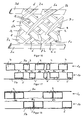
- This structure of longitudinally L successive and spaced intermediate mixing elements 4 could, for example, with the in FIG. 2 illustrated sub-mixer insert 2b with mixing elements 5 or with the in FIG. 7 shown sub-mixer insert 2c and 2d, forming the mixer elements 5, to be assembled.
- the mixer elements 4 and 5 can also be created by the same number of sub-mixer inserts, as in the Figures 1 and 2 shown with a sub-mixer insert 2a, 2b, or as in FIG. 13 shown with two sub-mixer inserts 2a, 2b; 2c, 2d, or as in FIG. 15 only partially visible, each with three sub-mixer inserts 2a, 2b, 2c and not apparent sub-mixer inserts 2d, 2e, 2f.
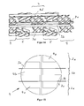
- This in FIG. 15 shown mixing element 4 has a substantially cylindrical outer contour on, for example, in FIG. 2 in the direction L outer contour shown.
- the mixing elements 4,5 in the longitudinal direction L are designed to be substantially as long or slightly shorter than the spaces Za, Zb, so that the mixing elements 4,5 in the interstices Za, For example, are insertable.
- the FIGS. 17 and 18 schematically show two sub-mixer inserts 2a, 2b with longitudinal webs 3a, 3b, on which mixing elements are arranged 4.5.
- no such opening 3e is formed, wherein the webs 6,6a, 6b, 7,7a, 7b are configured so flexible, and for example made of plastic, that the webs 6,6a, 6b, 7,7a , 7b slightly distort where the longitudinal webs 3a, 3b, 3c, 3d are arranged to provide this space.
- the additional webs 7, 7a, 7b could also be designed such that they are connected at their tips, where possible, also with the respective longitudinal web 3a, 3b, 3c, 3d.
Abstract
Description
Die Erfindung betrifft einen Mischereinsatz für einen statischen Mischer gemäss dem Oberbegriff von Anspruch 1. Die Erfindung betrifft weiter einen statischen Mischer gemäss dem Oberbegriff von Anspruch 15. Die Erfindung betrifft weiter ein Verfahren zum Herstellen eines Mischereinsatzes gemäss dem Oberbegriff von Anspruch 16.The invention relates to a mixer insert for a static mixer according to the preamble of claim 1. The invention further relates to a static mixer according to the preamble of claim 15. The invention further relates to a method for producing a mixer insert according to the preamble of claim 16.
Die Druckschrift
Es ist Aufgabe der vorliegenden Erfindung einen wirtschaftlich vorteilhafteren Mischereinsatz, einen vorteilhafteren statischen Mischer sowie ein vorteilhafteres Verfahren zum Herstellen eines Mischereinsatzes vorzuschlagen.It is an object of the present invention to propose a more economically advantageous mixer insert, a more advantageous static mixer and a more advantageous method for producing a mixer insert.
Diese Aufgabe wird gelöst mit einem Mischereinsatz aufweisend die Merkmale von Anspruch 1. Die Unteransprüche 2 bis 14 betreffen weitere, vorteilhaft ausgestaltete Mischereinsätze. Die Aufgabe wird weiter gelöst mit einem statischen Mischer aufweisend die Merkmale von Anspruch 15 sowie mit einem Verfahren zum Herstellen eines Mischereinsatzes aufweisend die Merkmale von Anspruch 16.This object is achieved with a mixer insert having the features of claim 1. The
Die Aufgabe wird insbesondere gelöst mit einem Mischereinsatz für einen statischen Mischer, umfassend eine Mehrzahl von entlang einer Längsachse nacheinander folgend angeordneten Mischelementen, welche aus sich kreuzenden Stegen bestehen, wobei der Mischereinsatz aus zumindest zwei Teilmischereinsätzen besteht, wobei jeder Teilmischereinsatz einen in Richtung der Längsachse verlaufenden Längssteg und Mischelemente umfasst, wobei der Längssteg peripher zu den Mischelementen angeordneten ist und fest mit den Mischelementen verbunden ist, wobei die Mischelemente des ersten Teilmischereinsatzes in Richtung der Längsachse unter Ausbildung von Zwischenräumen beabstandet sind, und wobei die Mischelemente des zweiten Teilmischereinsatzes in Richtung der Längsachse unter Ausbildung von Zwischenräumen beabstandet sind, wobei die Zwischenräume zumindest derart lang ausgestaltet sind, dass die Mischelemente des zweiten Teilmischereinsatzes in die Zwischenräume des ersten Teilmischereinsatzes einführbar sind, und dass die Mischelemente des ersten Teilmischereinsatzes in die Zwischenräume des zweiten Teilmischereinsatzes einführbar sind, um derart die Teilmischereinsätze und deren Mischelemente entlang einer gemeinsamen Längsachse nacheinander folgend anzuordnen.The object is achieved in particular with a mixer insert for a static mixer, comprising a plurality of mixing elements arranged one after the other along a longitudinal axis, which consist of intersecting webs, wherein the mixer insert consists of at least two sub-mixer inserts, each sub-mixer insert comprises a longitudinal web extending in the longitudinal axis and mixing elements, wherein the longitudinal web is arranged peripherally to the mixing elements and fixedly connected to the mixing elements, wherein the mixing elements the first sub-mixer insert are spaced in the direction of the longitudinal axis with the formation of intermediate spaces, and wherein the mixing elements of the second sub-mixer insert are spaced in the direction of the longitudinal axis with the formation of gaps, wherein the interstices are at least designed so long that the mixing elements of the second sub-mixer insert in the interstices of the first sub-mixer insert are insertable, and that the mixing elements of the first sub-mixer insert are insertable into the interstices of the second sub-mixer insert to the sub-mixer inserts and d Heen mixing elements along a common longitudinal axis successively to arrange.
Der erfindungsgemässe Mischereinsatz weist den Vorteil auf, dass dieser ausgehend von einer Mehrzahl vorgegebener Teilmischereinsätzen sehr schnell zusammengestellt werden kann, indem die Teilmischereinsätze entsprechend miteinander verbunden werden. In der einfachsten Ausführungsform besteht der Mischereinsatz aus zwei Teilmischereinsätzen, wobei die Mischelemente des ersten Teilmischereinsatzes in die Zwischenräume des zweiten Teilmischereinsatzes eingeführt werden, und umgekehrt, indem die Mischelemente des zweiten Teilmischereinsatzes in die Zwischenräume des ersten Teilmischereinsatzes eingeführt werden. Da die Mischelemente jedes Teilmischereinsatzes fest mit einem Längssteg verbunden sind, ist die Lage der Mischelemente jedes Teilmischereinsatzes vorgegeben, sodass die Teilmischereinsätze sehr einfach zum Mischeinsatz zusammengebaut werden können. Ein Mischereinsatz umfasst vorzugsweise vier bis sechzehn in Längsrichtung hintereinander angeordnete Mischelemente und ist beispielsweise mit zwei, vier, sechs oder acht Teilmischereinsätzen zusammenbaubar. Ein derartiger Mischereinsatz kann in sehr kurzer Zeit zusammenbaut werden. Zudem ist sichergestellt, dass alle Mischelemente um denselben Winkel bezüglich der Längsachse gegenseitig verdreht angeordnet sind, üblicherweise um 90 Grad, und auch bei einer Bewegung des Mischers während der Montage sich in der Lage nicht verändern.The mixer insert according to the invention has the advantage that, starting from a plurality of predetermined sub-mixer inserts, it can be assembled very quickly by connecting the sub-mixer inserts accordingly. In the simplest embodiment, the mixer insert consists of two sub-mixer inserts, wherein the mixing elements of the first sub-mixer insert are introduced into the interspaces of the second sub-mixer insert, and vice versa, by introducing the mixing elements of the second sub-mixer insert into the interspaces of the first sub-mixer insert. Since the mixing elements of each sub-mixer insert are fixedly connected to a longitudinal web, the position of the mixing elements is each Partial mixer insert predetermined, so that the sub-mixer inserts can be easily assembled to the mixing insert. A mixer insert preferably comprises four to sixteen mixing elements arranged one behind the other in the longitudinal direction and can be assembled, for example, with two, four, six or eight partial mixer inserts. Such a mixer insert can be assembled in a very short time. In addition, it is ensured that all mixing elements are mutually rotated by the same angle with respect to the longitudinal axis, usually by 90 degrees, and even in a movement of the mixer during assembly in the situation does not change.
Die Teilmischereinsätze bestehen vorzugsweise aus Kunststoff oder Metall und werden vorzugsweise im Spritzgussverfahren, im Präzisionsgussverfahren (Wachsausschmelzverfahren) oder im Druckgussverfahren hergestellt. Die Mischelemente weisen sich kreuzende Stege auf, weshalb zur Herstellung der Teilmischereinsätze in einem möglichen Herstellungsverfahren aufwendige, sehr teure, mehrteilige Werkzeuge mit Schiebereinsätzen erforderlich sind, um die Mischelemente mit ineinander greifenden Stegen herzustellen. In einer besonders vorteilhaften Ausführungsform wird daher darauf geachtet, dass die Teilmischereinsätze derart geometrisch ausgestaltet sind, dass diese sehr kostengünstig durch Spritzgiessen herstellbar sind. Ein kostengünstiger Spritzguss wird insbesondere dadurch erreicht, dass ein einfaches "Auf-Zu-Werkzeug" verwendet wird, wobei unter einem "Auf-Zu-Werkzeug" ein Werkzeug verstanden wird, welches zum Herstellen des Teilmischereinsatzes nur mittels einer Linearbewegung geöffnet und geschlossen werden muss. Mit solchen einfachen Werkzeugen können bei der Produktion in der Regel auch kurze Zykluszeiten und somit eine hohe Produktivität erzielt werden. Mit anderen Worten bedeutet dies, dass der gesamte Mischereinsatz in derart geometrisch ausgestaltete Teilmischereinsätze unterteil wird, dass die einzelnen Teilmischereinsätze sehr kostengünstig herstellbar sind, insbesondere durch Spritzguss mit einem "Auf-Zu-Werkzeug". In einer vorteilhaften Ausgestaltung bildet jeder Teilmischereinsatz nur ein Teilmischelement aus, wobei das Zusammenfügen mehrerer Teilmischereinsätze aus den jeweiligen Teilmischelementen das vollständige Mischelement ausbildet. Dies ermöglicht es durch Kombination beziehungsweise durch Zusammenbauen der kostengünstig hergestellten Teilmischelemente beliebig komplex ausgestaltete Mischelemente beziehungsweise Mischereinsätze mit sich kreuzenden Stegen herzustellen. Ein derartiger Mischereinsatz kann aus einer Vielzahl von Teilmischelementen bestehen, welche kostengünstig durch Spritzguss herstellbar sind. Trotz dieser möglichen Vielzahl an Teilmischelementen ist der Mischereinsatz sehr einfach zusammenbaubar, weil jeweils eine Mehrzahl von Teilmischelementen fest mit dem Längssteg verbunden sind, und derart einen Teilmischereinsatz ausbilden, wobei der gegenseitige Abstand als auch die Ausrichtung der Teilmischelemente durch den Verlauf des Längssteges vorgegeben ist. Ein Mischereinsatz besteht vorzugsweise aus insgesamt aus zwei, vier, sechs oder acht Teilmischelementen, und besteht somit aus einer geringen Anzahl von Einzelteilen, die zusammengebaut werden müssen.The sub-mixer inserts are preferably made of plastic or metal and are preferably produced by injection molding, precision casting (lost wax) or die casting. The mixing elements have intersecting webs, which is why expensive, very expensive, multi-part tools with slide inserts are required to produce the mixing elements with interlocking webs to produce the sub-mixer inserts in a possible manufacturing process. In a particularly advantageous embodiment, therefore, care is taken that the sub-mixer inserts are designed geometrically such that they are very inexpensive to produce by injection molding. Cost-effective injection molding is achieved, in particular, by using a simple "open-close tool", whereby a "open-close tool" is understood to be a tool which only has to be opened and closed to produce the sub-mixer insert by means of a linear movement , With such simple tools, production times can generally also be short cycle times and thus high productivity be achieved. In other words, this means that the entire mixer insert is subdivided into such geometrically configured sub-mixer inserts, that the individual sub-mixer inserts are very inexpensive to produce, in particular by injection molding with an "open-to-tool". In an advantageous embodiment, each sub-mixer insert forms only one sub-mixing element, wherein the joining of several sub-mixer inserts from the respective sub-mixing elements forms the complete mixing element. This makes it possible by combination or by assembling the cost-effectively produced sub-mixing elements arbitrarily complex designed mixing elements or mixer inserts with intersecting webs produce. Such a mixer insert may consist of a plurality of sub-mixing elements, which are inexpensive to produce by injection molding. Despite this possible variety of sub-mixing elements of the mixer insert is very easy to assemble, because a plurality of sub-mixing elements are firmly connected to the longitudinal web, and so form a sub-mixer insert, the mutual distance and the orientation of the sub-mixing elements is determined by the course of the longitudinal web. A mixer insert preferably consists of a total of two, four, six or eight sub-mixing elements, and thus consists of a small number of items that need to be assembled.
Der erfindungsgemässe Mischereinsatz kann somit sehr einfach aus kostengünstig herstellbaren Teilmischereinsätzen zusammengebaut werden, wobei die Mischelemente üblicherweise eine Vielzahl von sich kreuzenden Stegen aufweisen. Der erfindungsgemässe Mischereinsatz weist das vorteilhafte Mischverhalten eines statischen Mischers mit sich kreuzenden Stegen auf, ist jedoch wesentlich billiger herzustellen als bisher bekannte statische Mischer mit sich kreuzenden Stegen. Der erfindungsgemässe Mischereinsatz ist daher insbesondere auch als Wegwerfmischer geeignet.The mixer insert according to the invention can thus be assembled very easily from cost-effectively manufacturable partial mixer inserts, wherein the mixing elements usually have a multiplicity of intersecting webs. The inventive mixer insert has the advantageous mixing behavior of a static Mischers with intersecting webs, but is much cheaper to produce than previously known static mixer with intersecting webs. The mixer insert according to the invention is therefore particularly suitable as a disposable mixer.
Die Längsstege der Teilmischereinsätze weisen zudem den Vorteil auf, dass diese in Längsrichtung wirkende Kräfte ableiten, und insbesondere auf ein Aussengehäuse übertragen, sodass die in Längsrichtung wirkenden Kräfte nicht einzig von den Mischelementen übertragen werden müssen, wie dies aus dem Stand der Technik bekannt ist, sondern teilweise oder mehrheitlich von den Längsstegen übernommen werden. Dies ergibt die Vorteile, dass die Mischelemente beziehungsweise deren Stege mit geringerer Materialstärke gebildet werden können, was die Material- und Herstellungskosten reduziert, dass der Leervolumenanteil im statischen Mischer vergrössert ist, da der Mischereinsatz ein geringeres Materialvolumen aufweist, und dass dadurch der Mischereinsatz einen geringeren Strömungswiderstand aufweist.The longitudinal webs of the sub-mixer inserts also have the advantage that these derive longitudinal forces, and in particular transferred to an outer housing, so that the forces acting in the longitudinal direction must not be transmitted solely from the mixing elements, as is known in the prior art, but partially or majority of the longitudinal webs are taken. This results in the advantages that the mixing elements or their webs can be formed with lower material thickness, which reduces the material and manufacturing costs that the void volume fraction is increased in the static mixer, since the mixer insert has a lower volume of material, and thereby the mixer use a smaller Has flow resistance.
Die Erfindung wird nachfolgend anhand von Ausführungsbeispielen näher erläutert. Die Figuren zeigen:
- Fig. 1
- eine Seitenansicht eines ersten Teilmischereinsatzes;
- Fig. 2
- eine Seitenansicht eines zweiten Teilmischereinsatzes;
- Fig. 3
- ein zusammengestellter Mischereinsatz;
- Fig. 4
- eine Darstellung der Rückseite des in
Figur 3 dargestellten Mischereinsatzes; - Fig. 5
- eine Frontansicht des in
Figur 1 dargestellten Teilmischereinsatzes aus Richtung A; - Fig. 6
- eine Frontansicht des in
Figur 2 - Fig. 7
- eine Seitenansicht von zwei Teilmischereinsätzen;
- Fig. 8
- eine Frontansicht des in
Figur 7 dargestellten Teilmischereinsatzes aus Richtung C; - Fig. 9
- eine Detailansicht des in
Figur 7 dargestellten Teilmischereinsatzes; - Fig. 10
- eine Draufsicht auf die in
Figur 9 - Fig. 11
- eine dreidimensionale Detailansicht der in
Figur 7 dargestellten Teilmischereinsätze; - Fig. 12
- einen noch nicht zusammengestellten Mischereinsatz umfassend vier Teilmischereinsätze;
- Fig. 13
- eine Frontansicht des in
Figur 12 dargestellten Teilmischereinsatzes aus Richtung D; - Fig. 14
- eine dreidimensionale Detailansicht der in
Figur 12 dargestellten Teilmischereinsätze; - Fig. 15
- eine Frontansicht eines Mischereinsatzes umfassend drei übereinander angeordnete Teilmischereinsätze;
- Fig. 16
- eine dreidimensionale Detailansicht von zwei Teilmischereinsätzen aufweisend Einraststellen;
- Fig. 17
- schematisch ein Ausführungsbeispiel einer möglichen Anordnung von Mischelementen im Mischereinsatz;
- Fig. 18
- schematisch ein Ausführungsbeispiel einer weiteren möglichen Anordnung von Mischelementen im Mischereinsatz;
- Fig. 1
- a side view of a first part mixer insert;
- Fig. 2
- a side view of a second sub-mixer insert;
- Fig. 3
- a composite mixer insert;
- Fig. 4
- a representation of the back of the in
FIG. 3 illustrated mixer insert; - Fig. 5
- a front view of the in
FIG. 1 illustrated sub-mixer insert from direction A; - Fig. 6
- a front view of the in
FIG. 2 illustrated sub-mixer insert from direction B; - Fig. 7
- a side view of two sub-mixer inserts;
- Fig. 8
- a front view of the in
FIG. 7 illustrated sub-mixer insert from direction C; - Fig. 9
- a detailed view of the in
FIG. 7 illustrated sub-mixer insert; - Fig. 10
- a top view of the in
FIG. 9 illustrated detail view of a sub-mixer insert; - Fig. 11
- a three-dimensional detail view of in
FIG. 7 shown sub-mixer inserts; - Fig. 12
- a not yet assembled mixer insert comprising four sub-mixer inserts;
- Fig. 13
- a front view of the in
FIG. 12 shown sub-mixer insert from direction D; - Fig. 14
- a three-dimensional detail view of in
FIG. 12 shown sub-mixer inserts; - Fig. 15
- a front view of a mixer insert comprising three stacked sub-mixer inserts;
- Fig. 16
- a three-dimensional detail view of two sub-mixer inserts having latching points;
- Fig. 17
- schematically an embodiment of a possible arrangement of mixing elements in the mixer insert;
- Fig. 18
- schematically an embodiment of another possible arrangement of mixing elements in the mixer insert;
In
Die in den
Der in
Übereinander angeordnete Teilmischereinsätze 2c,2d können nicht nur wie in
Die
Es kann sich, wie in
Bisher wurden nur Ausführungsformen von Teilmischereinsätzen 2a,2b,2c,2d gezeigt, deren Mischelemente 4,5 in Längsrichtung L im wesentlichen ebenso lang oder leicht kürzer ausgestaltet sind wie die Zwischenräume Za,Zb, sodass die Mischelemente 4,5 in die Zwischenräume Za,Zb einführbar sind. Die
Es kann sich als vorteilhaft erweisen Grund- und Zusatzstege 6,6a,6b,7,7a,7b, welche zu einem Längssteg 3a,3b,3c,3d hin angeordnet sind, an deren Peripherie geringfügig zu kürzen, sodass, der Teilmischereinsatz 2a,2b, wie in
In einer weiteren vorteilhaften Ausgestaltung ist keine derartige Öffnung 3e ausgebildet, wobei die Stege 6,6a,6b,7,7a,7b derart flexibel ausgestaltet sind, und beispielsweise aus Kunststoff bestehen, dass sich die Stege 6,6a,6b,7,7a,7b an denjenigen Stellen leicht verkrümmen, wo die Längsstege 3a,3b,3c,3d angeordnet sind, um diesen Platz zu schaffen. Die Zusatzstege 7,7a,7b könnten auch derart ausgestaltet sein, dass diese an deren Spitzen, wo möglich, auch mit dem jeweiligen Längssteg 3a,3b,3c,3d verbunden sind.In a further advantageous embodiment, no such opening 3e is formed, wherein the
Claims (17)
Priority Applications (1)
| Application Number | Priority Date | Filing Date | Title |
|---|---|---|---|
| EP07112131A EP2011562A1 (en) | 2007-07-06 | 2007-07-10 | Mixer insert, static mixing device and method for manufacturing a static mixer insert |
Applications Claiming Priority (2)
| Application Number | Priority Date | Filing Date | Title |
|---|---|---|---|
| EP07111997 | 2007-07-06 | ||
| EP07112131A EP2011562A1 (en) | 2007-07-06 | 2007-07-10 | Mixer insert, static mixing device and method for manufacturing a static mixer insert |
Publications (1)
| Publication Number | Publication Date |
|---|---|
| EP2011562A1 true EP2011562A1 (en) | 2009-01-07 |
Family
ID=39427609
Family Applications (1)
| Application Number | Title | Priority Date | Filing Date |
|---|---|---|---|
| EP07112131A Withdrawn EP2011562A1 (en) | 2007-07-06 | 2007-07-10 | Mixer insert, static mixing device and method for manufacturing a static mixer insert |
Country Status (1)
| Country | Link |
|---|---|
| EP (1) | EP2011562A1 (en) |
Cited By (5)
| Publication number | Priority date | Publication date | Assignee | Title |
|---|---|---|---|---|
| WO2010066457A1 (en) * | 2008-12-10 | 2010-06-17 | Technische Universiteit Eindhoven | Static mixer comprising a static mixing element, method of mixing a fluid in a conduit and a formula for designing such a static mixing element |
| DE102015121351A1 (en) | 2015-12-08 | 2017-06-08 | Stamixco Ag | Mixer insert, static mixer and manufacturing process |
| US9675943B2 (en) | 2013-03-14 | 2017-06-13 | Dow Global Technologies Llc | Two part molded part useful as a mixer for viscous curable materials |
| EP2566628B1 (en) | 2010-05-07 | 2017-09-06 | Dürr Systems AG | Atomizer with a lattice mixer |
| US10758927B2 (en) | 2015-12-23 | 2020-09-01 | Commonwealth Scientific And Industrial Research Organisation | Rotary device |
Citations (2)
| Publication number | Priority date | Publication date | Assignee | Title |
|---|---|---|---|---|
| CH642564A5 (en) * | 1979-10-26 | 1984-04-30 | Sulzer Ag | STATIC MIXING DEVICE. |
| CH678284A5 (en) * | 1988-11-03 | 1991-08-30 | Sulzer Ag | Static mixer assembly requiring no cleaning - in which inner face of tube segments bear ridges which cross each other diagonally with respect to tubular axis |
-
2007
- 2007-07-10 EP EP07112131A patent/EP2011562A1/en not_active Withdrawn
Patent Citations (2)
| Publication number | Priority date | Publication date | Assignee | Title |
|---|---|---|---|---|
| CH642564A5 (en) * | 1979-10-26 | 1984-04-30 | Sulzer Ag | STATIC MIXING DEVICE. |
| CH678284A5 (en) * | 1988-11-03 | 1991-08-30 | Sulzer Ag | Static mixer assembly requiring no cleaning - in which inner face of tube segments bear ridges which cross each other diagonally with respect to tubular axis |
Cited By (13)
| Publication number | Priority date | Publication date | Assignee | Title |
|---|---|---|---|---|
| WO2010066457A1 (en) * | 2008-12-10 | 2010-06-17 | Technische Universiteit Eindhoven | Static mixer comprising a static mixing element, method of mixing a fluid in a conduit and a formula for designing such a static mixing element |
| EP2566628B2 (en) † | 2010-05-07 | 2020-06-24 | Dürr Systems AG | Atomizer with a lattice mixer |
| EP2566628B1 (en) | 2010-05-07 | 2017-09-06 | Dürr Systems AG | Atomizer with a lattice mixer |
| US9675943B2 (en) | 2013-03-14 | 2017-06-13 | Dow Global Technologies Llc | Two part molded part useful as a mixer for viscous curable materials |
| US10265666B2 (en) | 2013-03-14 | 2019-04-23 | Dow Global Technologies Llc | Two part molded part useful as a mixer for viscous curable materials |
| CN105026025B (en) * | 2013-03-14 | 2017-11-21 | 陶氏环球技术有限责任公司 | It is suitable for the two-piece molded part of the blender of sticky curable materials |
| CN108367258A (en) * | 2015-12-08 | 2018-08-03 | 斯塔米克斯科股份有限公司 | Mixer plug-in unit, static mixer and manufacturing method |
| WO2017097860A1 (en) | 2015-12-08 | 2017-06-15 | Stamixco Ag | Mixer insert, static mixer and production method |
| DE102015121351A1 (en) | 2015-12-08 | 2017-06-08 | Stamixco Ag | Mixer insert, static mixer and manufacturing process |
| US10882014B2 (en) | 2015-12-08 | 2021-01-05 | Stamixco Ag | Mixer insert, static mixer and production method |
| CN108367258B (en) * | 2015-12-08 | 2021-09-24 | 斯塔米克斯科-Gpx-H有限公司 | Mixer insert, static mixer and method of manufacture |
| US10758927B2 (en) | 2015-12-23 | 2020-09-01 | Commonwealth Scientific And Industrial Research Organisation | Rotary device |
| US11541412B2 (en) | 2015-12-23 | 2023-01-03 | Commonwealth Scientific And Industrial Research Organisation | Static mixers for continuous flow catalytic reactors |
Similar Documents
| Publication | Publication Date | Title |
|---|---|---|
| EP3386617B1 (en) | Mixing insert, static mixer and productionmethod | |
| EP1815904B1 (en) | Mixing element for static mixer, static mixer and method of production of such a mixing element | |
| DE2826732C2 (en) | ||
| EP2548634B1 (en) | Mixing element for static mixer | |
| EP1216747B1 (en) | Static mixer | |
| DE1236479B (en) | Device for mixing flowing media, with stationary guide elements | |
| EP1510247B1 (en) | Static mixer with polymorphous structure | |
| EP3408014A1 (en) | Hollow chamber x-mixer heat exchanger | |
| EP2011562A1 (en) | Mixer insert, static mixing device and method for manufacturing a static mixer insert | |
| WO2007110316A1 (en) | Static mixer and process for producing it | |
| EP3495036B1 (en) | Mixer insert for static mixer, static mixer and method of manufacturing | |
| EP2714229B1 (en) | Filtering device for highly viscous fluids | |
| WO2017211528A1 (en) | Fiber-reinforced plastic component and method for producing same | |
| EP1133594A1 (en) | Bar assembly | |
| DE102013113679A1 (en) | Actuating device for a sliding sleeve in a manual transmission | |
| DE3718693A1 (en) | Bush-shaped injection-moulded component, particularly a roller bearing cage | |
| EP1837070A1 (en) | Static mixer, and method of manufacturing the same | |
| DE102016201263A1 (en) | fastening system | |
| DE202006012130U1 (en) | Helical static mixer is made up of rectangular, especially square plates, each of which is turned through angle with respect to preceding one, mixer being mounted in pipe | |
| AT408024B (en) | CONNECTING ELEMENT | |
| DE102017128116B4 (en) | Mixer component, static mixer and process for their preparation | |
| DE3900492C1 (en) | Rolling bearing for linear rolling-contact guideways | |
| DE10236068B4 (en) | Longitudinal adjuster for a vehicle seat | |
| DE202015105397U1 (en) | Static mixer and mixing device with such a mixer | |
| EP3338882A1 (en) | Mixing element with high strength and mixing effect |
Legal Events
| Date | Code | Title | Description |
|---|---|---|---|
| PUAI | Public reference made under article 153(3) epc to a published international application that has entered the european phase |
Free format text: ORIGINAL CODE: 0009012 |
|
| AK | Designated contracting states |
Kind code of ref document: A1 Designated state(s): AT BE BG CH CY CZ DE DK EE ES FI FR GB GR HU IE IS IT LI LT LU LV MC MT NL PL PT RO SE SI SK TR |
|
| AX | Request for extension of the european patent |
Extension state: AL BA HR MK RS |
|
| AKX | Designation fees paid | ||
| REG | Reference to a national code |
Ref country code: DE Ref legal event code: 8566 |
|
| STAA | Information on the status of an ep patent application or granted ep patent |
Free format text: STATUS: THE APPLICATION IS DEEMED TO BE WITHDRAWN |
|
| 18D | Application deemed to be withdrawn |
Effective date: 20090708 |