EP3393393B1 - Zahnmedizinisches und/oder chirurgisches instrument mit einer kartusche und entsprechende patrone - Google Patents
Zahnmedizinisches und/oder chirurgisches instrument mit einer kartusche und entsprechende patrone Download PDFInfo
- Publication number
- EP3393393B1 EP3393393B1 EP16708178.5A EP16708178A EP3393393B1 EP 3393393 B1 EP3393393 B1 EP 3393393B1 EP 16708178 A EP16708178 A EP 16708178A EP 3393393 B1 EP3393393 B1 EP 3393393B1
- Authority
- EP
- European Patent Office
- Prior art keywords
- dental
- surgical instrument
- cartridge
- head
- rotor
- Prior art date
- Legal status (The legal status is an assumption and is not a legal conclusion. Google has not performed a legal analysis and makes no representation as to the accuracy of the status listed.)
- Active
Links
Images

Classifications
-
- A—HUMAN NECESSITIES
- A61—MEDICAL OR VETERINARY SCIENCE; HYGIENE
- A61C—DENTISTRY; APPARATUS OR METHODS FOR ORAL OR DENTAL HYGIENE
- A61C1/00—Dental machines for boring or cutting ; General features of dental machines or apparatus, e.g. hand-piece design
- A61C1/08—Machine parts specially adapted for dentistry
- A61C1/14—Tool-holders, i.e. operating tool holders, e.g. burr holders
- A61C1/141—Tool-holders, i.e. operating tool holders, e.g. burr holders in an angled handpiece
-
- A—HUMAN NECESSITIES
- A61—MEDICAL OR VETERINARY SCIENCE; HYGIENE
- A61C—DENTISTRY; APPARATUS OR METHODS FOR ORAL OR DENTAL HYGIENE
- A61C1/00—Dental machines for boring or cutting ; General features of dental machines or apparatus, e.g. hand-piece design
- A61C1/08—Machine parts specially adapted for dentistry
- A61C1/18—Flexible shafts; Clutches or the like; Bearings or lubricating arrangements; Drives or transmissions
- A61C1/181—Bearings or lubricating arrangements, e.g. air-cushion bearings
-
- F—MECHANICAL ENGINEERING; LIGHTING; HEATING; WEAPONS; BLASTING
- F16—ENGINEERING ELEMENTS AND UNITS; GENERAL MEASURES FOR PRODUCING AND MAINTAINING EFFECTIVE FUNCTIONING OF MACHINES OR INSTALLATIONS; THERMAL INSULATION IN GENERAL
- F16C—SHAFTS; FLEXIBLE SHAFTS; ELEMENTS OR CRANKSHAFT MECHANISMS; ROTARY BODIES OTHER THAN GEARING ELEMENTS; BEARINGS
- F16C35/00—Rigid support of bearing units; Housings, e.g. caps, covers
- F16C35/04—Rigid support of bearing units; Housings, e.g. caps, covers in the case of ball or roller bearings
- F16C35/06—Mounting or dismounting of ball or roller bearings; Fixing them onto shaft or in housing
- F16C35/07—Fixing them on the shaft or housing with interposition of an element
- F16C35/077—Fixing them on the shaft or housing with interposition of an element between housing and outer race ring
-
- A—HUMAN NECESSITIES
- A61—MEDICAL OR VETERINARY SCIENCE; HYGIENE
- A61B—DIAGNOSIS; SURGERY; IDENTIFICATION
- A61B17/00—Surgical instruments, devices or methods
- A61B17/068—Surgical staplers, e.g. containing multiple staples or clamps
- A61B17/072—Surgical staplers, e.g. containing multiple staples or clamps for applying a row of staples in a single action, e.g. the staples being applied simultaneously
- A61B2017/07214—Stapler heads
- A61B2017/07271—Stapler heads characterised by its cartridge
-
- A—HUMAN NECESSITIES
- A61—MEDICAL OR VETERINARY SCIENCE; HYGIENE
- A61C—DENTISTRY; APPARATUS OR METHODS FOR ORAL OR DENTAL HYGIENE
- A61C1/00—Dental machines for boring or cutting ; General features of dental machines or apparatus, e.g. hand-piece design
- A61C1/08—Machine parts specially adapted for dentistry
- A61C1/14—Tool-holders, i.e. operating tool holders, e.g. burr holders
- A61C1/145—Instruments or accessories for tool holders
-
- F—MECHANICAL ENGINEERING; LIGHTING; HEATING; WEAPONS; BLASTING
- F16—ENGINEERING ELEMENTS AND UNITS; GENERAL MEASURES FOR PRODUCING AND MAINTAINING EFFECTIVE FUNCTIONING OF MACHINES OR INSTALLATIONS; THERMAL INSULATION IN GENERAL
- F16C—SHAFTS; FLEXIBLE SHAFTS; ELEMENTS OR CRANKSHAFT MECHANISMS; ROTARY BODIES OTHER THAN GEARING ELEMENTS; BEARINGS
- F16C19/00—Bearings with rolling contact, for exclusively rotary movement
- F16C19/54—Systems consisting of a plurality of bearings with rolling friction
- F16C19/546—Systems with spaced apart rolling bearings including at least one angular contact bearing
- F16C19/547—Systems with spaced apart rolling bearings including at least one angular contact bearing with two angular contact rolling bearings
-
- F—MECHANICAL ENGINEERING; LIGHTING; HEATING; WEAPONS; BLASTING
- F16—ENGINEERING ELEMENTS AND UNITS; GENERAL MEASURES FOR PRODUCING AND MAINTAINING EFFECTIVE FUNCTIONING OF MACHINES OR INSTALLATIONS; THERMAL INSULATION IN GENERAL
- F16C—SHAFTS; FLEXIBLE SHAFTS; ELEMENTS OR CRANKSHAFT MECHANISMS; ROTARY BODIES OTHER THAN GEARING ELEMENTS; BEARINGS
- F16C2316/00—Apparatus in health or amusement
- F16C2316/10—Apparatus in health or amusement in medical appliances, e.g. in diagnosis, dentistry, instruments, prostheses, medical imaging appliances
- F16C2316/13—Dental machines
Definitions
- the present invention relates to the field of medical instruments, more particularly dental and / or surgical instruments. More specifically, the present application relates to an improvement in the design of the dental and / or surgical instrument.
- the expression “instrument” is used as a generic term designating any working tool of a practitioner, in particular of a dentist or a surgeon.
- the expression “motor” universally designates any device capable of creating a mechanical movement (in particular a rotary, linear, oscillatory, ultrasonic movement, etc.)
- the expression “handpiece” generally designates the device which transmits or transforms such a mechanical movement
- the expression “head” designates the part of the handpiece consisting of the elements for transmitting the movement at a predefined angle, the guide elements, and the clamping elements of the tool .
- Dental and / or surgical instruments are already known comprising handpieces of the “turbine” type (with an air drive) or of the “contra-angle” type (with a motor and gear drive).
- the handpieces essentially comprise a system for clamping (and driving) the tool which is generally mounted on ball bearings.
- EP 0 527 473 An example of a document illustrating the solutions known to date and exhibiting the aforementioned defects is EP 0 527 473 where a large geometric error can occur in the alignment and concentricity of the ball bearings.
- EP 1 378 207 the two ball bearings are guided on two different bores, thus creating a risk of poor concentricity, and having a fairly complex ball bearing preload mechanism in terms of the number of components, the assembly kinematics, the qualification of the special staff and tools.
- FROM 43 24 493 also presents a preloading mechanism of the ball bearings rather complex in terms of the number of components, the assembly kinematics, the qualification of the personnel and the special tools, then also with a great susceptibility to shocks.
- an aim of the present invention is to provide a novel dental and / or surgical instrument which does not exhibit these defects of instruments known to date. More specifically, an aim of the present invention is to provide a dental and / or surgical instrument making it possible to reduce geometric errors as much as possible, to improve the distribution of the preload force of the bearings and the quality of engagement of the bearings. , provide superior impact resistance, reduce the number of precise parts to be machined and then assembled, and ultimately improve flexibility for after-sales service.
- the present invention consists essentially in pre-assembling the elements of the head in a “cartridge” (or in a “capsule”), the geometry of the cartridge being designed so as to optimize the positioning of the axes of transmission of the movement and alignment of the tool guiding and clamping elements.
- a cartridge according to the present invention can also be easily replaced, without resorting to special tools or methods.
- a removable cartridge which can be inserted into the head of a dental and / or surgical instrument according to the characteristics of claim 1, comprising a sleeve with a single cylindrical internal bore and a lateral opening, and a sub-assembly with a rotor, a first ball bearing, a second ball bearing, as well as a tool holder.
- the lateral opening of the sleeve is adapted for the connection between a driving shaft of a dental and / or surgical instrument and the rotor driving the tool holder in rotation, and the rotor comprises an external toothing capable of meshing with a corresponding toothing of the leading tree.
- the present invention relates to a dental and / or surgical instrument comprising a motor driving a tool through a tool holder located in the head of the dental and / or surgical instrument, as well as such removable cartridge, such that the tool holder is supported in the head of the dental and / or surgical instrument by the first ball bearing and the second ball bearing of the removable cartridge.
- Such a complete dental instrument provided with such a removable cartridge conferring improved guiding properties further reflects the modular configuration conferred by the present invention.
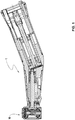
- a dental and / or surgical instrument 1 according to one embodiment of the present invention is shown schematically on figure 1 and a detail of its structure in figures 2 and 3 .
- it is in particular a “contra-angle” rotary dental and / or surgical instrument, therefore an instrument used to carry and drive a dental bur which is then used to remove the softened tooth tissue. by decay.
- This dental instrument 1 comprises in particular a cartridge 10 according to an embodiment of the present invention which will be described in more detail below.
- the present invention also relates to surgical instruments having the same structure.
- An important aim of the present invention is the provision of a dental and / or surgical instrument in which the geometric error is greatly reduced compared to existing solutions.
- the bearings which carry the tool clamping and guiding system in particular the milling cutter
- the present invention proposes to mount and guide the two bearings in the same bore (that is to say in a cylinder), which results in a minimization of the geometric error and other advantages mentioned below. . Otherwise, each additional staff or piece can double this relative error.
- the present invention proposes to create this cylinder for mounting and guiding the ball bearings in a socket called the diffuser and for mounting the motion transmission elements, as well as the guiding and clamping elements of the tool in this socket. Then the sleeve with the mounted elements is closed and secured before it is inserted into the head of the dental and / or surgical instrument.
- FIG. 2 with the sub- figures 2A to 2E shows the sequence of mounting the cartridge according to one embodiment of the present invention.
- a socket 11 is first made available as illustrated in figure 2A .
- This socket 11 contains a cylindrical bore 80 inside, as well as a side opening (illustrated by an arrow) which serves to connect the rotor 23 of the cartridge 10 to the driving shaft 41 of the dental instrument and / or surgical 1 (shown on figure 3 ).
- This cylindrical bore 80 serves to mount and guide both the first ball bearing and the second ball bearing which will be described later.
- the sub-assembly 20 with a rotor 23 is mounted in parallel, as can be seen at figure 2C .
- This sub-assembly 20 comprises the two ball bearings 21, 22, as well as the clamping and guiding elements of the tool (or a tool holder) 24, 25, 27.
- An external toothing (or pinion) 26 is provided on the rotor 23.
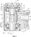
- This external toothing 26 meshes with the corresponding toothing 42 of the driving shaft 41 in order to drive this sub-assembly 20, and therefore also the tool when the dental and / or surgical instrument 1 is in operation. function, in rotation (cf. figure 3 ).
- This toothing 26 can form an integral part of the rotor 23, but can also be produced as a separate part and driven on the rotor 23.
- Figure 3 shows the head of the dental and / or surgical instrument 1 in the mounted state. It is visible that the cartridge 10 is inserted into the free space created by the wall 30 of the head, then blocked in the head by a standard locking mechanism 31. It is also visible at the bottom. figure 3 that the toothing (the pinion) 42 of the driving shaft 41 (which is driven by a motor which is not shown) meshes with the toothing 26 in the cartridge 10 in order to drive the clamping and guide elements of the 'tool 24, 25, 27 supported by the rotating ball bearings 21, 22. This drive shaft 41 is also supported by the ball bearings, only one of which (reference no. 43) is visible at the figure 3 .
- the end of the driving shaft 41 also serves for positioning and locking the cartridge 10. Indeed, and as visible at figure 3 , the end of the drive shaft 41 fits into the side opening (illustrated by an arrow at the figure 2A ) and can thus lock the cartridge 10 in the correct position.
- the dental and / or surgical instrument 1 in addition to the improvement of the geometry and the reduction of the corresponding error, also exhibits an improvement in the preload. bearings. Indeed, this point is closely linked to the geometric error cited above. If the two ball bearings 21, 22 are not concentric, the force applied for the preload will not be distributed evenly over the components of each bearing 21, 22. Rather, this force will split into components which can cause stress. parasites accelerating the degradation of each bearing 21, 22 in dynamics.
- the quality of engagement is also improved in a dental and / or surgical instrument 1 according to the present invention.
- the perpendicularity of the two transmission axes 41, 23 is also linked to the precision obtained in the machining of the sleeve (or of the diffuser) 11. The precision of this part will therefore directly influence the relative positioning between the two. transmission axes 41, 23 and thus improve the quality of meshing.
- Another advantage of the dental and / or surgical instrument 1 according to the present invention is the improvement in impact resistance.
- the contact zone of instrument 1 is very often its distal end.
- the impact energy will first be absorbed by the material of the head (i.e. by the outer shell) 30, then by the material of the cartridge 10 itself (therefore the wall 11).
- the chosen solution therefore makes it possible to obtain a multilayer effect thanks to the various rigidities of the materials and thus reduce the propagation of deformations which can destroy the ball bearings 21, 22.
Landscapes
- Health & Medical Sciences (AREA)
- Oral & Maxillofacial Surgery (AREA)
- Epidemiology (AREA)
- Dentistry (AREA)
- Life Sciences & Earth Sciences (AREA)
- Animal Behavior & Ethology (AREA)
- General Health & Medical Sciences (AREA)
- Public Health (AREA)
- Veterinary Medicine (AREA)
- General Engineering & Computer Science (AREA)
- Engineering & Computer Science (AREA)
- Mechanical Engineering (AREA)
- Dental Tools And Instruments Or Auxiliary Dental Instruments (AREA)
Claims (7)
- Lösbares Modul (10), eingerichtet um in den Kopf eines dentalen und/oder chirurgischen Instruments (1) eingeführt zu werden, umfassend:eine Hülse (11) mit einer einzigen zylindrischen inneren Bohrung (80) und einer seitlichen Öffnung, undeine Untereinheit (20) mit einem Rotor (23), einem ersten Kugellager (21), einem zweiten Kugellager (22) und einem Werkzeughalter (24, 25, 27), wobei die seitliche Öffnung der Hülse (11) eingerichtet ist für die Verbindung zwischen einer Antriebswelle (41) und einem dentalen und/oder chirurgischen Instrument (1) und der Rotor (23) den Werkzeughalter (24, 25, 27) in Drehung versetzt, wobei der Rotor (23) eine Aussenverzahnung (26) aufweist, welche mit einer zur Verzahnung der Antriebswelle (41) korrespondierenden Aussenverzahnung in Eingriff gebracht werden kann.
- Lösbares Modul (10) nach Anspruch 1, dadurch gekennzeichnet, dass die Bohrung (80) zumindest eine erste Nut (83) und eine zweite Nut (84) aufweist, wobei die erste Nut (83) vorgesehen ist, um eine erste Dämpfungsdichtung (12) aufzunehmen und die zweite Nut (84) vorgesehen ist, um eine zweite Dämpfungsdichtung (13) aufzunehmen.
- Dentales und/oder chirurgisches Instrument (1), welches einen Motor zum Antreiben eines Werkzeughalters (24, 25, 27) umfasst, angeordnet in dem Kopf des dentalen und/oder chirurgischen Instruments (1) und ein lösbares Modul (10) nach Anspruch 1, so dass der Werkzeughalter (24, 25, 27) in dem Kopf des dentalen und/oder chirurgischen Instruments (1) von dem ersten Kugellager (21) und dem zweiten Kugellager (22) des lösbaren Moduls (10) gehalten ist.
- Dentales und/oder chirurgisches Instrument (1) nach Anspruch 3, dadurch gekennzeichnet, dass das Modul (10) von einer Mutter (18) arretiert ist.
- Dentales und/oder chirurgisches Instrument (1) nach einem der Ansprüche 3 oder 4, dadurch gekennzeichnet, dass das Modul (10) in dem Kopf des dentalen und/oder chirurgischen Instruments (1) mittels dem Ende der Antriebswelle (41) positioniert und arretiert ist.
- Dentales und/oder chirurgisches Instrument (1) nach einem der Ansprüche 3 bis 5, dadurch gekennzeichnet, dass die zentrale Achse der Antriebswelle (41) senkrecht zu der Welle des Rotors (23) ist.
- Dentales und/oder chirurgisches Instrument (1) nach einem der Ansprüche 3 bis 5, dadurch gekennzeichnet, dass das Aussengehäuse (30) des dentalen und/oder chirurgischen Instruments (1) aus einem anderen Material gefertigt ist als das Material des Moduls (10).
Applications Claiming Priority (2)
| Application Number | Priority Date | Filing Date | Title |
|---|---|---|---|
| CH3152015 | 2015-03-07 | ||
| PCT/EP2016/054796 WO2016142342A1 (fr) | 2015-03-07 | 2016-03-07 | Instrument dentaire et/ou chirurgical avec une cartouche et une cartouche correspondante |
Publications (2)
| Publication Number | Publication Date |
|---|---|
| EP3393393A1 EP3393393A1 (de) | 2018-10-31 |
| EP3393393B1 true EP3393393B1 (de) | 2021-06-02 |
Family
ID=53871785
Family Applications (1)
| Application Number | Title | Priority Date | Filing Date |
|---|---|---|---|
| EP16708178.5A Active EP3393393B1 (de) | 2015-03-07 | 2016-03-07 | Zahnmedizinisches und/oder chirurgisches instrument mit einer kartusche und entsprechende patrone |
Country Status (5)
| Country | Link |
|---|---|
| US (1) | US10285779B2 (de) |
| EP (1) | EP3393393B1 (de) |
| JP (1) | JP6737820B2 (de) |
| CN (1) | CN107567318B (de) |
| WO (1) | WO2016142342A1 (de) |
Families Citing this family (3)
| Publication number | Priority date | Publication date | Assignee | Title |
|---|---|---|---|---|
| DE102017209613A1 (de) * | 2017-06-07 | 2018-12-13 | Sirona Dental Systems Gmbh | Dentales Hand- oder Winkelstück mit einem rotierenden Werkzeug |
| DE102019129940A1 (de) * | 2019-11-06 | 2021-05-06 | Gebr. Reinfurt Gmbh & Co. Kg | Dentalhandstück |
| DE102021204812A1 (de) * | 2021-05-12 | 2022-11-17 | Minebea Mitsumi Inc. | Kopflagerbaugruppe für ein dentalmedizinisches oder chirurgisches Handstück und dentalmedizinisches oder chirurgisches Handstück mit einer solchen Kopflagerbaugruppe |
Family Cites Families (14)
| Publication number | Priority date | Publication date | Assignee | Title |
|---|---|---|---|---|
| US3418715A (en) * | 1957-09-03 | 1968-12-31 | Ritter Pfaudler Corp | Dental handpiece drive mechanism and dental tool holder |
| GB1367733A (en) * | 1972-04-04 | 1974-09-25 | Dental Mfg Eng Ltd | High speed turbines |
| JPS5150891U (de) * | 1974-10-17 | 1976-04-17 | ||
| JPS5588757U (de) * | 1978-12-15 | 1980-06-19 | ||
| JPS56166014U (de) * | 1980-05-15 | 1981-12-09 | ||
| JPS6026693B2 (ja) * | 1980-05-27 | 1985-06-25 | 積水化成品工業株式会社 | 屈曲フイルムの製造方法 |
| JPH0714397B2 (ja) * | 1991-08-12 | 1995-02-22 | 株式会社中西歯科器械製作所 | 歯科用ハンドピース |
| AT400510B (de) | 1992-08-12 | 1996-01-25 | Buermoos Dentalwerk | Spannvorrichtung für ein dentales winkelstück |
| JPH0838509A (ja) * | 1994-07-28 | 1996-02-13 | Iwata Denko Kk | 歯科用ハンドピース |
| JP3014379U (ja) * | 1995-02-06 | 1995-08-08 | 株式会社中西歯科器械製作所 | 歯科用ハンドピースのカートリッジ |
| JPH09117458A (ja) * | 1995-10-25 | 1997-05-06 | Osada Res Inst Ltd | 歯科用ハンドピース |
| DE10229649A1 (de) | 2002-07-02 | 2004-01-22 | Kaltenbach & Voigt Gmbh & Co. Kg | Medizinisches oder dentalmedizinisches Handstück mit einer Drucktaste zum Lösen eines Werkzeugs |
| FR2882917B1 (fr) * | 2005-03-14 | 2008-07-04 | Micro Mega Int Mfg Sa | "dispositif d'accrochage d'un intrument dentaire sur une piece a main forme d'un ensemble axe tournant, ressort d'accrochage et bouton poussoir" |
| CH699665A2 (fr) * | 2008-10-07 | 2010-04-15 | Bien Air Holding Sa | Piece a main a usage dentaire ou chirurgical. |
-
2016
- 2016-03-07 EP EP16708178.5A patent/EP3393393B1/de active Active
- 2016-03-07 CN CN201680014396.2A patent/CN107567318B/zh active Active
- 2016-03-07 WO PCT/EP2016/054796 patent/WO2016142342A1/fr not_active Ceased
- 2016-03-07 JP JP2017564953A patent/JP6737820B2/ja active Active
- 2016-03-07 US US15/552,628 patent/US10285779B2/en active Active
Non-Patent Citations (1)
| Title |
|---|
| None * |
Also Published As
| Publication number | Publication date |
|---|---|
| JP6737820B2 (ja) | 2020-08-12 |
| US10285779B2 (en) | 2019-05-14 |
| WO2016142342A1 (fr) | 2016-09-15 |
| CN107567318A (zh) | 2018-01-09 |
| JP2018510745A (ja) | 2018-04-19 |
| CN107567318B (zh) | 2020-11-10 |
| EP3393393A1 (de) | 2018-10-31 |
| US20180021105A1 (en) | 2018-01-25 |
Similar Documents
| Publication | Publication Date | Title |
|---|---|---|
| EP3827186B1 (de) | Planetengetriebe für gasturbine | |
| EP1701019A1 (de) | Zweiwellenturbomaschine mit Antriebsmodul auf Niederdruck- und Hochdruckrotoren, Antriebsmodul für die Turbomaschine und Montageverfahren der Turbomaschine | |
| EP3649373B1 (de) | Zahnkranz für ein epizyklisches- oder planetenuntersetzungsgetriebe einer turbomaschine | |
| EP3209458B1 (de) | Verbesserte vibrationsbearbeitungsvorrichtung | |
| EP3393393A1 (de) | Zahnmedizinisches und/oder chirurgisches instrument mit einer kartusche und entsprechende patrone | |
| EP3313623A1 (de) | Tragbares elektrowerkzeug mit einem epizyklischen untersetzungsgetriebe | |
| EP3649378A1 (de) | Zahnkranz für ein epizyklisches- oder planetenuntersetzungsgetriebe einer turbomaschine | |
| FR3018712A1 (fr) | Outil de percage a deux moteurs coaxiaux | |
| EP1954447A1 (de) | Winkelkopf-schraubendrehwerkzeug mit einem an der ausgangswelle angebrachten drehmomentsensor und entsprechendes kraftübertragungsmodul | |
| FR2720264A1 (fr) | Matériel d'implant dentaire et dispositif pour sa mise en place. | |
| EP1674761B1 (de) | Planetenrad Getriebeaufbau | |
| EP1995009A1 (de) | Fräsmaschinenkopf | |
| FR2897133A1 (fr) | Procede de fabrication d'un reducteur, reducteur et robot incorporant un tel reducteur | |
| FR3006617A1 (fr) | Dispositif d'usinage vibratoire | |
| EP3803159A1 (de) | Verfahren zum zusammenbau eines untersetzungsgetriebes und anlage zur durchführung des verfahrens | |
| CH703961B1 (fr) | Méthode d'assemblage d'une pièce en matériau dur sur un axe et ensemble comprenant une telle pièce assemblée sur un axe. | |
| EP2365784A1 (de) | Handstück für dentale oder chirurgische anwendungen | |
| FR3075898A1 (fr) | Arbre de transmission pour une turbomachine | |
| EP2488921B1 (de) | Energiequelle für ein schlagwerk und uhr mit einer derartigen energiequelle | |
| FR3038954A1 (fr) | Boite de transmission de puissance et aeronef | |
| EP4375522B1 (de) | Geräuscharmes mechanisches untersetzungsgetriebe-satellitengleitlager | |
| EP0281847A1 (de) | Zahnärztliches Handstück | |
| WO2012004544A1 (fr) | Pompe a eau a entrainement reversible | |
| WO2024052005A1 (fr) | Instrument endodontique comprenant une portion d'assemblage améliorée | |
| CH721805A2 (fr) | Masse oscillante annulaire et pièce d'horlogerie comportant une telle masse oscillante |
Legal Events
| Date | Code | Title | Description |
|---|---|---|---|
| STAA | Information on the status of an ep patent application or granted ep patent |
Free format text: STATUS: THE INTERNATIONAL PUBLICATION HAS BEEN MADE |
|
| STAA | Information on the status of an ep patent application or granted ep patent |
Free format text: STATUS: THE APPLICATION IS DEEMED TO BE WITHDRAWN |
|
| PUAI | Public reference made under article 153(3) epc to a published international application that has entered the european phase |
Free format text: ORIGINAL CODE: 0009012 |
|
| STAA | Information on the status of an ep patent application or granted ep patent |
Free format text: STATUS: REQUEST FOR EXAMINATION WAS MADE |
|
| 17P | Request for examination filed |
Effective date: 20180413 |
|
| AK | Designated contracting states |
Kind code of ref document: A1 Designated state(s): AL AT BE BG CH CY CZ DE DK EE ES FI FR GB GR HR HU IE IS IT LI LT LU LV MC MK MT NL NO PL PT RO RS SE SI SK SM TR |
|
| AX | Request for extension of the european patent |
Extension state: BA ME |
|
| RIN1 | Information on inventor provided before grant (corrected) |
Inventor name: JUILLERAT, SEBASTIEN Inventor name: SCHENK, MARC |
|
| STAA | Information on the status of an ep patent application or granted ep patent |
Free format text: STATUS: EXAMINATION IS IN PROGRESS |
|
| 17Q | First examination report despatched |
Effective date: 20200407 |
|
| GRAP | Despatch of communication of intention to grant a patent |
Free format text: ORIGINAL CODE: EPIDOSNIGR1 |
|
| STAA | Information on the status of an ep patent application or granted ep patent |
Free format text: STATUS: GRANT OF PATENT IS INTENDED |
|
| DAV | Request for validation of the european patent (deleted) | ||
| DAX | Request for extension of the european patent (deleted) | ||
| INTG | Intention to grant announced |
Effective date: 20201102 |
|
| GRAJ | Information related to disapproval of communication of intention to grant by the applicant or resumption of examination proceedings by the epo deleted |
Free format text: ORIGINAL CODE: EPIDOSDIGR1 |
|
| STAA | Information on the status of an ep patent application or granted ep patent |
Free format text: STATUS: EXAMINATION IS IN PROGRESS |
|
| INTC | Intention to grant announced (deleted) | ||
| GRAS | Grant fee paid |
Free format text: ORIGINAL CODE: EPIDOSNIGR3 |
|
| STAA | Information on the status of an ep patent application or granted ep patent |
Free format text: STATUS: GRANT OF PATENT IS INTENDED |
|
| GRAP | Despatch of communication of intention to grant a patent |
Free format text: ORIGINAL CODE: EPIDOSNIGR1 |
|
| GRAA | (expected) grant |
Free format text: ORIGINAL CODE: 0009210 |
|
| STAA | Information on the status of an ep patent application or granted ep patent |
Free format text: STATUS: THE PATENT HAS BEEN GRANTED |
|
| INTG | Intention to grant announced |
Effective date: 20210421 |
|
| REG | Reference to a national code |
Ref country code: CH Ref legal event code: EP |
|
| AK | Designated contracting states |
Kind code of ref document: B1 Designated state(s): AL AT BE BG CH CY CZ DE DK EE ES FI FR GB GR HR HU IE IS IT LI LT LU LV MC MK MT NL NO PL PT RO RS SE SI SK SM TR |
|
| REG | Reference to a national code |
Ref country code: GB Ref legal event code: FG4D Free format text: NOT ENGLISH |
|
| REG | Reference to a national code |
Ref country code: AT Ref legal event code: REF Ref document number: 1397730 Country of ref document: AT Kind code of ref document: T Effective date: 20210615 |
|
| REG | Reference to a national code |
Ref country code: IE Ref legal event code: FG4D Free format text: LANGUAGE OF EP DOCUMENT: FRENCH |
|
| REG | Reference to a national code |
Ref country code: DE Ref legal event code: R096 Ref document number: 602016058771 Country of ref document: DE |
|
| REG | Reference to a national code |
Ref country code: LT Ref legal event code: MG9D |
|
| PG25 | Lapsed in a contracting state [announced via postgrant information from national office to epo] |
Ref country code: BG Free format text: LAPSE BECAUSE OF FAILURE TO SUBMIT A TRANSLATION OF THE DESCRIPTION OR TO PAY THE FEE WITHIN THE PRESCRIBED TIME-LIMIT Effective date: 20210902 Ref country code: HR Free format text: LAPSE BECAUSE OF FAILURE TO SUBMIT A TRANSLATION OF THE DESCRIPTION OR TO PAY THE FEE WITHIN THE PRESCRIBED TIME-LIMIT Effective date: 20210602 Ref country code: FI Free format text: LAPSE BECAUSE OF FAILURE TO SUBMIT A TRANSLATION OF THE DESCRIPTION OR TO PAY THE FEE WITHIN THE PRESCRIBED TIME-LIMIT Effective date: 20210602 Ref country code: LT Free format text: LAPSE BECAUSE OF FAILURE TO SUBMIT A TRANSLATION OF THE DESCRIPTION OR TO PAY THE FEE WITHIN THE PRESCRIBED TIME-LIMIT Effective date: 20210602 |
|
| REG | Reference to a national code |
Ref country code: NL Ref legal event code: MP Effective date: 20210602 |
|
| PG25 | Lapsed in a contracting state [announced via postgrant information from national office to epo] |
Ref country code: LV Free format text: LAPSE BECAUSE OF FAILURE TO SUBMIT A TRANSLATION OF THE DESCRIPTION OR TO PAY THE FEE WITHIN THE PRESCRIBED TIME-LIMIT Effective date: 20210602 Ref country code: GR Free format text: LAPSE BECAUSE OF FAILURE TO SUBMIT A TRANSLATION OF THE DESCRIPTION OR TO PAY THE FEE WITHIN THE PRESCRIBED TIME-LIMIT Effective date: 20210903 Ref country code: NO Free format text: LAPSE BECAUSE OF FAILURE TO SUBMIT A TRANSLATION OF THE DESCRIPTION OR TO PAY THE FEE WITHIN THE PRESCRIBED TIME-LIMIT Effective date: 20210902 Ref country code: PL Free format text: LAPSE BECAUSE OF FAILURE TO SUBMIT A TRANSLATION OF THE DESCRIPTION OR TO PAY THE FEE WITHIN THE PRESCRIBED TIME-LIMIT Effective date: 20210602 Ref country code: RS Free format text: LAPSE BECAUSE OF FAILURE TO SUBMIT A TRANSLATION OF THE DESCRIPTION OR TO PAY THE FEE WITHIN THE PRESCRIBED TIME-LIMIT Effective date: 20210602 Ref country code: SE Free format text: LAPSE BECAUSE OF FAILURE TO SUBMIT A TRANSLATION OF THE DESCRIPTION OR TO PAY THE FEE WITHIN THE PRESCRIBED TIME-LIMIT Effective date: 20210602 |
|
| PG25 | Lapsed in a contracting state [announced via postgrant information from national office to epo] |
Ref country code: SM Free format text: LAPSE BECAUSE OF FAILURE TO SUBMIT A TRANSLATION OF THE DESCRIPTION OR TO PAY THE FEE WITHIN THE PRESCRIBED TIME-LIMIT Effective date: 20210602 Ref country code: SK Free format text: LAPSE BECAUSE OF FAILURE TO SUBMIT A TRANSLATION OF THE DESCRIPTION OR TO PAY THE FEE WITHIN THE PRESCRIBED TIME-LIMIT Effective date: 20210602 Ref country code: CZ Free format text: LAPSE BECAUSE OF FAILURE TO SUBMIT A TRANSLATION OF THE DESCRIPTION OR TO PAY THE FEE WITHIN THE PRESCRIBED TIME-LIMIT Effective date: 20210602 Ref country code: EE Free format text: LAPSE BECAUSE OF FAILURE TO SUBMIT A TRANSLATION OF THE DESCRIPTION OR TO PAY THE FEE WITHIN THE PRESCRIBED TIME-LIMIT Effective date: 20210602 Ref country code: PT Free format text: LAPSE BECAUSE OF FAILURE TO SUBMIT A TRANSLATION OF THE DESCRIPTION OR TO PAY THE FEE WITHIN THE PRESCRIBED TIME-LIMIT Effective date: 20211004 Ref country code: NL Free format text: LAPSE BECAUSE OF FAILURE TO SUBMIT A TRANSLATION OF THE DESCRIPTION OR TO PAY THE FEE WITHIN THE PRESCRIBED TIME-LIMIT Effective date: 20210602 Ref country code: RO Free format text: LAPSE BECAUSE OF FAILURE TO SUBMIT A TRANSLATION OF THE DESCRIPTION OR TO PAY THE FEE WITHIN THE PRESCRIBED TIME-LIMIT Effective date: 20210602 Ref country code: ES Free format text: LAPSE BECAUSE OF FAILURE TO SUBMIT A TRANSLATION OF THE DESCRIPTION OR TO PAY THE FEE WITHIN THE PRESCRIBED TIME-LIMIT Effective date: 20210602 |
|
| REG | Reference to a national code |
Ref country code: DE Ref legal event code: R097 Ref document number: 602016058771 Country of ref document: DE |
|
| PLBE | No opposition filed within time limit |
Free format text: ORIGINAL CODE: 0009261 |
|
| STAA | Information on the status of an ep patent application or granted ep patent |
Free format text: STATUS: NO OPPOSITION FILED WITHIN TIME LIMIT |
|
| PG25 | Lapsed in a contracting state [announced via postgrant information from national office to epo] |
Ref country code: DK Free format text: LAPSE BECAUSE OF FAILURE TO SUBMIT A TRANSLATION OF THE DESCRIPTION OR TO PAY THE FEE WITHIN THE PRESCRIBED TIME-LIMIT Effective date: 20210602 |
|
| 26N | No opposition filed |
Effective date: 20220303 |
|
| PG25 | Lapsed in a contracting state [announced via postgrant information from national office to epo] |
Ref country code: AL Free format text: LAPSE BECAUSE OF FAILURE TO SUBMIT A TRANSLATION OF THE DESCRIPTION OR TO PAY THE FEE WITHIN THE PRESCRIBED TIME-LIMIT Effective date: 20210602 |
|
| PG25 | Lapsed in a contracting state [announced via postgrant information from national office to epo] |
Ref country code: IT Free format text: LAPSE BECAUSE OF FAILURE TO SUBMIT A TRANSLATION OF THE DESCRIPTION OR TO PAY THE FEE WITHIN THE PRESCRIBED TIME-LIMIT Effective date: 20210602 |
|
| PG25 | Lapsed in a contracting state [announced via postgrant information from national office to epo] |
Ref country code: MC Free format text: LAPSE BECAUSE OF FAILURE TO SUBMIT A TRANSLATION OF THE DESCRIPTION OR TO PAY THE FEE WITHIN THE PRESCRIBED TIME-LIMIT Effective date: 20210602 |
|
| GBPC | Gb: european patent ceased through non-payment of renewal fee |
Effective date: 20220307 |
|
| REG | Reference to a national code |
Ref country code: BE Ref legal event code: MM Effective date: 20220331 |
|
| REG | Reference to a national code |
Ref country code: AT Ref legal event code: UEP Ref document number: 1397730 Country of ref document: AT Kind code of ref document: T Effective date: 20210602 |
|
| PG25 | Lapsed in a contracting state [announced via postgrant information from national office to epo] |
Ref country code: LU Free format text: LAPSE BECAUSE OF NON-PAYMENT OF DUE FEES Effective date: 20220307 Ref country code: IE Free format text: LAPSE BECAUSE OF NON-PAYMENT OF DUE FEES Effective date: 20220307 Ref country code: GB Free format text: LAPSE BECAUSE OF NON-PAYMENT OF DUE FEES Effective date: 20220307 |
|
| PG25 | Lapsed in a contracting state [announced via postgrant information from national office to epo] |
Ref country code: BE Free format text: LAPSE BECAUSE OF NON-PAYMENT OF DUE FEES Effective date: 20220331 |
|
| P01 | Opt-out of the competence of the unified patent court (upc) registered |
Effective date: 20230530 |
|
| PG25 | Lapsed in a contracting state [announced via postgrant information from national office to epo] |
Ref country code: HU Free format text: LAPSE BECAUSE OF FAILURE TO SUBMIT A TRANSLATION OF THE DESCRIPTION OR TO PAY THE FEE WITHIN THE PRESCRIBED TIME-LIMIT; INVALID AB INITIO Effective date: 20160307 |
|
| PG25 | Lapsed in a contracting state [announced via postgrant information from national office to epo] |
Ref country code: MK Free format text: LAPSE BECAUSE OF FAILURE TO SUBMIT A TRANSLATION OF THE DESCRIPTION OR TO PAY THE FEE WITHIN THE PRESCRIBED TIME-LIMIT Effective date: 20210602 Ref country code: CY Free format text: LAPSE BECAUSE OF FAILURE TO SUBMIT A TRANSLATION OF THE DESCRIPTION OR TO PAY THE FEE WITHIN THE PRESCRIBED TIME-LIMIT Effective date: 20210602 |
|
| PG25 | Lapsed in a contracting state [announced via postgrant information from national office to epo] |
Ref country code: MT Free format text: LAPSE BECAUSE OF FAILURE TO SUBMIT A TRANSLATION OF THE DESCRIPTION OR TO PAY THE FEE WITHIN THE PRESCRIBED TIME-LIMIT Effective date: 20210602 |
|
| PGFP | Annual fee paid to national office [announced via postgrant information from national office to epo] |
Ref country code: CH Payment date: 20250401 Year of fee payment: 10 |
|
| PG25 | Lapsed in a contracting state [announced via postgrant information from national office to epo] |
Ref country code: TR Free format text: LAPSE BECAUSE OF FAILURE TO SUBMIT A TRANSLATION OF THE DESCRIPTION OR TO PAY THE FEE WITHIN THE PRESCRIBED TIME-LIMIT Effective date: 20210602 |
|
| REG | Reference to a national code |
Ref country code: CH Ref legal event code: U11 Free format text: ST27 STATUS EVENT CODE: U-0-0-U10-U11 (AS PROVIDED BY THE NATIONAL OFFICE) Effective date: 20260401 |
|
| PGFP | Annual fee paid to national office [announced via postgrant information from national office to epo] |
Ref country code: DE Payment date: 20260319 Year of fee payment: 11 |
|
| PGFP | Annual fee paid to national office [announced via postgrant information from national office to epo] |
Ref country code: AT Payment date: 20260320 Year of fee payment: 11 |
|
| PGFP | Annual fee paid to national office [announced via postgrant information from national office to epo] |
Ref country code: FR Payment date: 20260320 Year of fee payment: 11 |