EP3393295B1 - Wheeled luggage comprising a retractable rod - Google Patents
Wheeled luggage comprising a retractable rod Download PDFInfo
- Publication number
- EP3393295B1 EP3393295B1 EP16826128.7A EP16826128A EP3393295B1 EP 3393295 B1 EP3393295 B1 EP 3393295B1 EP 16826128 A EP16826128 A EP 16826128A EP 3393295 B1 EP3393295 B1 EP 3393295B1
- Authority
- EP
- European Patent Office
- Prior art keywords
- tubes
- suitcase
- wheeled
- tube
- baggage
- Prior art date
- Legal status (The legal status is an assumption and is not a legal conclusion. Google has not performed a legal analysis and makes no representation as to the accuracy of the status listed.)
- Active
Links
- 230000035939 shock Effects 0.000 claims description 9
- 230000000295 complement effect Effects 0.000 claims description 4
- 238000005304 joining Methods 0.000 claims description 2
- 208000031968 Cadaver Diseases 0.000 description 10
- 238000005096 rolling process Methods 0.000 description 9
- 230000006378 damage Effects 0.000 description 5
- 238000013016 damping Methods 0.000 description 2
- 239000000463 material Substances 0.000 description 2
- 230000003014 reinforcing effect Effects 0.000 description 2
- 235000004443 Ricinus communis Nutrition 0.000 description 1
- 238000004026 adhesive bonding Methods 0.000 description 1
- 230000001627 detrimental effect Effects 0.000 description 1
- 210000003141 lower extremity Anatomy 0.000 description 1
- 238000004519 manufacturing process Methods 0.000 description 1
- 239000002184 metal Substances 0.000 description 1
- 239000000203 mixture Substances 0.000 description 1
- 238000000465 moulding Methods 0.000 description 1
- 230000002787 reinforcement Effects 0.000 description 1
- 238000009877 rendering Methods 0.000 description 1
Images


Classifications
-
- A—HUMAN NECESSITIES
- A45—HAND OR TRAVELLING ARTICLES
- A45C—PURSES; LUGGAGE; HAND CARRIED BAGS
- A45C13/00—Details; Accessories
- A45C13/26—Special adaptations of handles
- A45C13/262—Special adaptations of handles for wheeled luggage
-
- A—HUMAN NECESSITIES
- A45—HAND OR TRAVELLING ARTICLES
- A45C—PURSES; LUGGAGE; HAND CARRIED BAGS
- A45C13/00—Details; Accessories
- A45C13/26—Special adaptations of handles
-
- A—HUMAN NECESSITIES
- A45—HAND OR TRAVELLING ARTICLES
- A45C—PURSES; LUGGAGE; HAND CARRIED BAGS
- A45C5/00—Rigid or semi-rigid luggage
- A45C5/03—Suitcases
-
- A—HUMAN NECESSITIES
- A45—HAND OR TRAVELLING ARTICLES
- A45C—PURSES; LUGGAGE; HAND CARRIED BAGS
- A45C5/00—Rigid or semi-rigid luggage
- A45C5/14—Rigid or semi-rigid luggage with built-in rolling means
-
- A—HUMAN NECESSITIES
- A45—HAND OR TRAVELLING ARTICLES
- A45C—PURSES; LUGGAGE; HAND CARRIED BAGS
- A45C5/00—Rigid or semi-rigid luggage
- A45C5/03—Suitcases
- A45C2005/037—Suitcases with a hard shell, i.e. rigid shell as volume creating element
-
- A—HUMAN NECESSITIES
- A45—HAND OR TRAVELLING ARTICLES
- A45C—PURSES; LUGGAGE; HAND CARRIED BAGS
- A45C13/00—Details; Accessories
- A45C13/26—Special adaptations of handles
- A45C13/262—Special adaptations of handles for wheeled luggage
- A45C2013/267—Special adaptations of handles for wheeled luggage the handle being slidable, extractable and lockable in one or more positions
Definitions
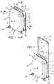
- the baggage shown on the figure 1 is of the "trolley” type and comprises a luggage body 1 comprising two half-shells 2 and 3 of substantially rectangular section, connected together by a hinge 4 which runs substantially over the entire height of the body 1 of the luggage, on one side 5 of the luggage (or side face 5).
- the half-shells are assembled together by their free edges 7 by means of a zipper 6 running all along the free edges 7 of the two half-shells 2 and 3.
- the double telescopic rod 16 also comprises a handle 18, connecting the two free ends 19 of the two arms 17.
Description
La présente invention est relative à un bagage roulant comportant un corps de bagage monté sur roulettes et une canne double reliée à une poignée, la canne double étant montée mobile sur le corps entre une position déployée permettant à un utilisateur de tracter manuellement le bagage et une position escamotée dans le corps.The present invention relates to a rolling baggage comprising a baggage body mounted on wheels and a double rod connected to a handle, the double rod being movably mounted on the body between a deployed position allowing a user to manually tow the baggage and a stowed position in the body.
Usuellement, une double canne mobile est réalisée sous la forme d'au moins deux bras, reliés par une poignée, les deux bras étant des tubes rigides montés coulissants respectivement dans deux tubes solidaires du corps du bagage. Le document
Les tubes recevant les bras sont positionnés à l'intérieur du bagage.The tubes receiving the arms are positioned inside the baggage.
Ce montage représente un certain volume qui est perdu pour l'utilisateur du bagage, et nécessite par ailleurs des pièces de renfort et de fixation qui nuisent à l'aspect esthétique et impliquent un surpoids, les tubes et les pièces de renfort et de fixation doivent typiquement être masquées pour un meilleur rendu esthétique, par exemple au moyen d'une doublure en toile.This assembly represents a certain volume which is lost for the user of the luggage, and moreover requires reinforcement and fixing parts which are detrimental to the aesthetic appearance and involve overweight, the tubes and the reinforcing and fixing parts must typically be hidden for a better aesthetic rendering, for example by means of a canvas lining.
Ce montage peut également conduire à la réalisation de parties en saillie sur les faces du corps du bagage, ce qui est inesthétique.This assembly can also lead to the production of projecting parts on the faces of the body of the baggage, which is unsightly.
Par ailleurs, le montage alourdit la masse du bagage, ce qui peut présenter un inconvénient pour l'utilisateur qui doit tracter son bagage et qui doit notamment respecter une limitation de poids de bagage imposée par les compagnies aériennes.Furthermore, the assembly increases the weight of the baggage, which can present a drawback for the user who must tow his baggage and who must in particular comply with a baggage weight limitation imposed by the airlines.
Les documents
La présente invention a notamment pour but de palier tout ou partie des inconvénients susmentionnés.The object of the present invention is in particular to overcome all or part of the aforementioned drawbacks.
A cet effet, l'invention propose un bagage roulant comportant :
- o un corps de bagage rigide ou semi-rigide, monté sur roulettes, ledit corps comportant au moins trois faces latérales rigides ou semi-rigides séparées par deux arêtes, et
- o une canne double télescopique comportant deux bras, une poignée et deux tubes, les bras étant reliés à la poignée et montés coulissants dans les deux tubes.
- o a rigid or semi-rigid baggage body, mounted on wheels, said body comprising at least three rigid or semi-rigid side faces separated by two ridges, and
- o a double telescopic rod with two arms, one handle and two tubes, the arms being connected to the handle and slidably mounted in the two tubes.
Conformément à l'invention, le bagage est remarquable en ce que les deux tubes sont disposés le long des deux arêtes à l'extérieur du corps dudit bagage.According to the invention, the baggage is remarkable in that the two tubes are arranged along the two ridges outside the body of said baggage.
En positionnant les tubes à l'extérieur du corps du bagage, le volume intérieur utile du bagage n'est pas réduit et le fond du bagage est plat. De plus, en positionnant les tubes le long des arêtes, la double canne s'adapte à une partie du contour d'une face du bagage. Ainsi, les tubes ne forment aucune saillie sur une face du bagage, ce qui rend l'ensemble du bagage esthétique.By positioning the tubes outside the body of the luggage, the useful internal volume of the luggage is not reduced and the bottom of the luggage is flat. In addition, by positioning the tubes along the ridges, the double rod adapts to part of the contour of one side of the luggage. Thus, the tubes do not form any protrusion on one side of the baggage, which makes the whole baggage aesthetic.
Conformément à l'invention, chacune des deux arêtes est conformée en creux, présentant une concavité tournée vers l'extérieur du corps du bagage, les tubes étant reçus dans les arêtes en creux.According to the invention, each of the two ridges is shaped as a hollow, having a concavity turned towards the outside of the body of the baggage, the tubes being received in the hollow ridges.
Conformément à plusieurs modes de réalisation qui seront décrits par la suite, le bagage conforme à l'invention peut comporter les caractéristiques suivantes, prises séparément ou en combinaison :
- chacun des tubes présente un profilé avec une section définie par une portion extérieure et une portion intérieure, la portion extérieure définissant un arc présentant deux extrémités, les deux extrémités joignant tangentiellement deux faces latérales contigües à l'arête dans laquelle le tube est reçu, la portion intérieure étant configurée pour épouser sensiblement la concavité de ladite arête en creux dans laquelle le tube est reçu,
- les tubes sont fixés aux deux arêtes par des rivets ou des vis,
- les tubes présentent des extrémités ouvertes par lesquels les bras sont introduits, et une pièce intermédiaire rigide est positionnée entre les tubes et s'étend de l'extrémité ouverte d'un tube à l'extrémité ouverte de l'autre tube,
- l'une des faces latérales est une face arrière de corps de bagage, et ledit corps de bagage comporte une face de dessus séparée de la face arrière par une arête supérieure de corps de bagage, ladite arête supérieure étant conformée en creux, présentant une concavité tournée vers l'extérieur du corps du bagage, la pièce intermédiaire rigide étant de forme complémentaire à la concavité de l'arête supérieure et la pièce intermédiaire étant fixée dans ladite arête supérieure,
- la poignée est mobile entre une position rétractée et une position déployée et comprend, sur au moins une portion de sa longueur, une section définie par une portion extérieure de poignée et une portion intérieure de poignée, la portion extérieure de poignée définissant un arc présentant deux extrémités, les deux extrémités se trouvant dans le prolongement de plans définis par, respectivement, une face latérale du corps du bagage et la face de dessus du corps du bagage,
- le bagage comporte un espace libre entre la poignée et la pièce intermédiaire rigide en position rétractée de la poignée,
- le bagage comprend en outre au moins deux dispositifs à roulettes montés pivotants autour de deux axes de pivotement respectifs, lesdits dispositifs à roulettes étant rapportés sur une face du dessous du corps du bagage,
- les tubes présentent une extrémité de tube située au voisinage d'un dispositif à roulettes, ladite extrémité de tube présentant un bord délimitant un espace interne au tube, et l'axe de pivotement du dispositif à roulettes se prolonge dans ledit espace interne au tube,
- chaque dispositif à roulettes est fixé au voisinage d'un tube auquel il est associé, et chacun des deux axes de pivotement est parallèle à un axe principal de tube auquel ledit dispositif à roulettes est associé, un axe de pivotement d'un dispositif à roulettes étant espacé d'un axe principal de tube qui lui est associé d'une distance inférieure à 20 millimètres, de préférence nulle,
- chacun des dispositifs à roulettes est fixé à un élément rapporté sur un tube,
- le bagage comporte des dispositifs amortisseurs de choc,
- les dispositifs amortisseurs de chocs sont des pièces rapportées sur une face latérale dudit corps dudit bagage, au voisinage des tubes,
- les tubes comportent lesdits dispositifs amortisseurs de choc.
- each of the tubes has a profile with a section defined by an outer portion and an inner portion, the outer portion defining an arc having two ends, the two ends tangentially joining two side faces contiguous to the edge in which the tube is received, the inner portion being configured to substantially match the concavity of said hollow ridge in which the tube is received,
- the tubes are fixed to the two edges by rivets or screws,
- the tubes have open ends through which the arms are introduced, and a rigid intermediate piece is positioned between the tubes and extends from the open end of one tube to the open end of the other tube,
- one of the side faces is a rear face of the luggage body, and said luggage body has a top face separated from the rear face by an upper edge of the luggage body, said upper edge being shaped as a hollow, having a concavity facing the outside of the body of the baggage, the rigid intermediate piece being of a shape complementary to the concavity of the upper edge and the intermediate piece being fixed in said upper edge,
- the handle is movable between a retracted position and a deployed position and comprises, over at least a portion of its length, a section defined by an outer handle portion and an inner handle portion, the outer handle portion defining an arc having two ends, the two ends being in the extension of planes defined by, respectively, a side face of the body of the baggage and the top face of the body of the baggage,
- the baggage has a free space between the handle and the rigid intermediate piece in the retracted position of the handle,
- the baggage further comprises at least two roller devices mounted to pivot about two respective pivot axes, said roller devices being attached to a face of the underside of the body of the baggage,
- the tubes have a tube end located in the vicinity of a roller device, said tube end having an edge delimiting a space internal to the tube, and the pivot axis of the roller device extends into said space internal to the tube,
- each roller device is fixed in the vicinity of a tube with which it is associated, and each of the two pivot axes is parallel to a main tube axis with which said roller device is associated, a pivot axis of a roller device being spaced from a main tube axis associated with it by a distance of less than 20 millimeters, preferably zero,
- each of the rolling devices is attached to an element attached to a tube,
- the luggage has shock absorbing devices,
- shock-absorbing devices are attached parts on a lateral face of said body of said baggage, in the vicinity of the tubes,
- the tubes include said shock absorbing devices.
D'autres caractéristiques et avantages de l'invention apparaîtront au cours de la description suivante de plusieurs formes de réalisation, données à titre d'exemples non limitatifs, en regard des dessins joints.Other characteristics and advantages of the invention will become apparent from the following description of several embodiments, given by way of non-limiting examples, with reference to the accompanying drawings.
Sur les dessins :
- la
figure 1 est une vue en perspective d'un bagage roulant conforme à l'invention, dont la double canne est en position rétractée, - la
figure 2 est une vue en perspective du bagage montré enfigure 1 , dont la double canne est en position déployée, - la
figure 3 est une vue en perspective d'une partie du bagage montré enfigure 2 , dévoilant l'intérieur du bagage et notamment du fond du bagage portant la double canne, - la
figure 4 est une vue de derrière du bagage illustré sur lafigure 2 , - la
figure 5 est une vue de côté du bagage illustré sur lafigure 2 , - la
figure 6 est une vue de face du bagage montré enfigure 1 , - la
figure 7 est une vue de dessus du bagage montré enfigure 1 , - la
figure 8 est une vue partielle de derrière du bagage, avec la double canne en position rétractée, - la
figure 9 est une vue en coupe partielle d'une partie supérieure du bagage selon le plan IX-IX montré enfigure 1 , - et la
figure 10 est une vue en coupe partielle d'une partie latérale du bagage selon le plan X-X montré enfigure 1 .
- the
figure 1 is a perspective view of a rolling baggage according to the invention, the double rod of which is in the retracted position, - the
figure 2 is a perspective view of the baggage shown infigure 1 , whose double rod is in the deployed position, - the
figure 3 is a perspective view of part of the baggage shown infigure 2 , revealing the inside of the luggage and in particular the bottom of the luggage carrying the double rod, - the
figure 4 is a rear view of the baggage shown on thefigure 2 , - the
figure 5 is a side view of the baggage illustrated onfigure 2 , - the
figure 6 is a front view of the baggage shown infigure 1 , - the
figure 7 is a top view of the luggage shown infigure 1 , - the
figure 8 is a partial rear view of the baggage, with the double rod in the retracted position, - the
figure 9 is a partial sectional view of an upper part of the baggage according to the plan IX-IX shown infigure 1 , - and the
figure 10 is a partial sectional view of a side part of the baggage according to the plane XX shown infigure 1 .
Les figures qui vont être décrites montrent un mode de réalisation d'un bagage conforme à l'invention.The figures which will be described show an embodiment of a piece of luggage according to the invention.
Sur les différentes figures, les mêmes références désignent des éléments identiques ou similaires. De plus, les termes « inférieur », « supérieur », « haut », « bas », « avant », « arrière » etc... sont utilisés en référence aux dessins pour une plus grande facilité de compréhension. Ils ne doivent pas être compris comme étant des limitations de la portée de l'invention.In the various figures, the same references designate identical or similar elements. In addition, the terms "lower", "upper", "top", "bottom", "front", "rear" etc ... are used with reference to the drawings for ease of understanding. They should not be understood as being limitations on the scope of the invention.
Le bagage représenté sur la
Les demi-coques 2 et 3 sont des coques rigides ou semi-rigides, par exemple obtenues au moins en partie par moulage.The half-
Les demi-coques sont assemblées ensemble par leur bords libres 7 au moyen d'une fermeture à glissière 6 courant tout du long des bords libres 7 des deux demi-coques 2 et 3.The half-shells are assembled together by their
On comprendra par « bord libre 7 » le bord de chacune des demi-coques qui n'est pas relié à la charnière 4. La
Les deux demi-coques 2 et 3 assemblées forment les six faces latérales du bagage roulant : deux faces latérales 5, une face avant 8, une face arrière 9, une face de dessus 10 et une face de dessous 11.The two assembled half-
Les deux faces latérales 5, la face de dessus 10 et la face de dessous 11 sont formées par deux bords latéraux des demi-coques assemblés entre eux par la charnière 4 ou par la fermeture à glissière 6.The two side faces 5, the
Les faces avant 8 et arrière 9 constituent également des faces latérales du bagage quand le corps 1 est positionné debout (voir sur les
Les faces latérales 5, 8 et 9 (comprenant les faces avant et arrière), de dessus et de dessous sont délimitées par des arêtes 12, 13 ou 14 du corps 1.The side faces 5, 8 and 9 (comprising the front and rear faces), above and below are delimited by
La demi-coque 2 comporte les quatre arêtes de la face avant du corps 1 du bagage. Les arêtes 12 sont de forme arrondie. Dans les exemples illustrés par les figures, deux éléments de renfort 15 sont fixés aux coins supérieurs de la demi-coque 2.The half-
La demi-coque 3 formant l'arrière du corps 1 du bagage présente deux arêtes latérales 13 en creux, le creux formant une concavité, et la concavité étant tournée vers l'extérieur du corps du bagage. L'arête en creux peut également être appelée arête à bords tombés.The half-
La demi-coque 3 présente également une arête 14 supérieure de corps de bagage, séparant la face arrière 9 de la face de dessus 10 du corps du bagage. L'arête 14 supérieure est également réalisée en creux, dont la concavité est tournée vers l'extérieur du corps 1 du bagage. L'arête séparant la face de dessous 11 de la face arrière 9 est une arête 12 de forme arrondie, comme les arêtes de la demi-coque formant l'avant du corps 1 du bagage.The half-
Le corps 1 du bagage est monté sur quatre jeux de dispositifs à roulettes 30, chaque dispositif comportant deux roulettes.The
Il devra être entendu que les dispositifs à roulettes pourraient être différents sans sortir du cadre de l'invention ; par exemple, les dispositifs pourraient ne comporter qu'une seule roulette ou plus de deux roulettes.It should be understood that the devices with wheels could be different without departing from the scope of the invention; for example, the devices could have only one castor or more than two casters.
Chaque dispositif à roulettes 30 est rapporté et fixé à un coin de la face inférieure 11 du corps 1 du bagage.Each
Chacun des dispositifs à roulettes est monté mobile autour d'un axe X1 qui est parallèle à la direction des arêtes 12 ou 13 du corps 1 du bagage.Each of the rolling devices is movably mounted around an axis X1 which is parallel to the direction of the
Il devra être entendu que l'invention n'est pas limitée à la présence de quatre dispositifs à roulettes : en effet, le bagage pourrait ne comporter que deux dispositifs à roulettes, sans sortir du cadre de l'invention.It should be understood that the invention is not limited to the presence of four devices with wheels: indeed, the baggage could include only two devices with wheels, without departing from the scope of the invention.
Dans l'exemple illustré, deux des quatre dispositifs à roulettes sont associés aux deux tubes 21 en étant fixés sous les extrémités inférieures des deux tubes 21.In the example illustrated, two of the four roller devices are associated with the two
Les extrémités inférieures 39 (
Dans le cadre du mode de réalisation illustré (voir
Un autre mode de réalisation (non illustré) pourrait également être prévu, suivant lequel chaque dispositif à roulettes est fixé au voisinage d'un tube auquel il est associé, et chacun des deux axes de pivotement est parallèle à un axe principal X de tube auquel ledit dispositif à roulettes est associé, un axe de pivotement X1 d'un dispositif à roulettes étant espacé d'un axe principal X de tube qui lui est associé d'une distance inférieure à 20 millimètres.Another embodiment (not shown) could also be provided, according to which each roller device is fixed in the vicinity of a tube with which it is associated, and each of the two pivot axes is parallel to a main axis X of the tube to which said roller device is associated, a pivot axis X1 of a roller device being spaced from a main tube axis X which is associated with it by a distance of less than 20 millimeters.
Dans un tel cas, l'axe de pivotement des dispositifs à roulette est déporté de l'axe des tubes.In such a case, the pivot axis of the roller devices is offset from the axis of the tubes.
De préférence, la distance entre l'axe de pivotement X1 d'un dispositif à roulettes et l'axe principal X du tube qui lui est associé peut être choisie nulle.Preferably, the distance between the pivot axis X1 of a device with wheels and the main axis X of the tube associated with it can be chosen zero.
Il pourrait également être prévu, sans sortir du cadre de l'invention, que chacun des dispositifs à roulettes soit fixé à un élément rapporté sur un tube 21.Provision could also be made, without departing from the scope of the invention, for each of the roller devices to be fixed to an element attached to a
Conformément à l'invention, le bagage roulant comporte une canne double télescopique 16, fixée sur le corps 1 du bagage, et pouvant adopter une multitude de positions entre deux positions extrêmes : une position escamotée montrée sur les
La canne double télescopique 16 comporte deux bras 17 parallèles, réalisés chacun à partir d'une ou plusieurs tiges assemblées ensemble.The double
La canne double télescopique 16 comporte également une poignée 18, reliant les deux extrémités libres 19 des deux bras 17.The double
La poignée peut être équipée d'un bouton de déverrouillage 20 de la canne double lorsqu'elle est en position rétractée (ou escamotée) de manière à autoriser un passage de la position rétractée à la position déployée.The handle can be equipped with a
Les deux bras 17 de la canne double 16 sont montés coulissants dans deux tubes 21, et les deux tubes 21 sont fixés le long des arêtes 13 de la demi coque 3 formant l'arrière du corps 1 du bagage à l'extérieur de la demi-coque 3 et donc du corps 1 du bagage (voir
De cette façon, et comme on peut le voir en particulier sur la
Plus précisément, les tubes sont profilés avec une section définie par une portion extérieure 22 et une portion intérieure 23 (voir
La portion extérieure 22 définit un arc (ou autrement dit une courbe) dont les extrémités 24 et 25 joignent tangentiellement les faces latérale 5 et arrière 9 du corps 1 du bagage (les faces 5 et 9 étant contiguës).The
De cette façon, la portion extérieure 22 du tube 21 semble prolonger la face latérale 5 et la face arrière 9. Ainsi, visuellement, les tubes 21 s'inscrivent dans le prolongement des faces du bagage et se fondent dans l'encombrement du bagage, l'encombrement du bagage étant délimité latéralement par les faces 5, 9 et 8 du bagage.In this way, the
De cette façon, les tubes 21 n'encombrent pas le volume intérieur du bagage . En effet, si les tubes 21 étaient disposés à l'intérieur du bagage, comme il est usuel, ils pourraient détériorer les éléments contenus dans le bagage.In this way, the
On peut ainsi noter que le volume utile du bagage (c'est-à-dire le volume interne du bagage pouvant accueillir des objets correspond à au moins 80 % du volume délimité par la surface extérieure du bagage.It can thus be noted that the useful volume of the baggage (that is to say the internal volume of the baggage that can accommodate objects corresponds to at least 80% of the volume delimited by the outer surface of the baggage.
Par ailleurs, les tubes 21 ne nuisent pas à esthétique extérieure du bagage.Furthermore, the
Enfin, ils ne sont pas saillants à l'extérieur du bagage, et ainsi moins fragiles.Finally, they are not protruding outside the baggage, and thus less fragile.
De façon générale, la surface extérieure (c'est-à-dire visible) des tubes 21 engagés dans les creux 13, forment des arêtes de bagage qui sont de forme et de taille sensiblement identiques aux arêtes 12. Ainsi, le corps du bagage est compact et présente une forme extérieure régulière, symétrique, ce qui donne au bagage une forme élégante et esthétique attendue par le consommateur.In general, the outer surface (that is to say visible) of the
Par ailleurs, comme montré en
Les tubes 21 sont fixés dans les arêtes en creux 13, par exemple au moyen de rivets ou de vis 26 (voir
Le fait que les tubes soient rapportés à l'extérieur du bagage par rivetage ou par vissage facilite l'assemblage du bagage.The fact that the tubes are attached to the outside of the baggage by riveting or by screwing facilitates assembly of the baggage.
Par ailleurs, les moyens de fixation des tubes de cannes ne nuisent pas à l'intégrité des éléments contenus dans le bagage. En effet, ils sont peu nombreux (deux par tube) et placés sensiblement aux extrémités des tubes et des arêtes du bagage.Furthermore, the means for fixing the rod tubes do not harm the integrity of the elements contained in the baggage. Indeed, they are few (two per tube) and placed substantially at the ends of the tubes and edges of the baggage.
Il est à rappeler que les parois formant les faces des bagages sont rigides ou semi-rigides. Aussi, il n'est pas nécessaire de prévoir deux traverses reliant les tubes que l'on trouve classiquement sur les bagages de type « trolley ».It should be remembered that the walls forming the faces of the luggage are rigid or semi-rigid. Also, it is not necessary to provide two cross members connecting the tubes that are conventionally found on luggage of the “trolley” type.
A la place de telles traverses, le bagage conforme à l'invention présente une pièce intermédiaire rigide, fixée dans l'arête en creux supérieure qui permet d'apporter une rigidité entre les deux tubes 21 en partie supérieure du bagage (voir
La pièce intermédiaire rigide 27 est placée entre les extrémités ouvertes 28 des tubes (les extrémités ouvertes 28 des tubes recevant les bras 17 de la canne double 16), de manière à maintenir les distance entre ces deux extrémités. En effet, sans cette pièce, la paroi formant la face arrière du corps 1 du bagage pourrait se déformer si l'utilisateur était amené à tirer le bagage en exerçant une traction sur un côté de la poignée 18 ou sur un bras 17, et la poignée pourrait alors rester bloquée dans une position intermédiaire entre la position déployée et la position escamotée, par un phénomène d'arc-boutement voire de déformation des bras ou des tubes.The rigid
La pièce intermédiaire 27 assure donc une rigidité de la partie supérieure du bagage.The
La pièce intermédiaire 27 est illustrée en
On peut également prévoir d'autres feuilles courbes rigides dans le fond des creux des arêtes en creux 13, entre le fond des arêtes en creux et les tubes 21.It is also possible to provide other rigid curved sheets in the bottom of the hollows of the
De tels feuilles courbes rigides sont fines et leur masse n'alourdit presque pas le bagage : dans tous les cas, beaucoup moins que la masse des traverses présentes usuellement dans les bagages type « trolley ».Such rigid curved sheets are thin and their mass hardly weighs down the baggage: in all cases, much less than the mass of the sleepers usually present in “trolley” type baggage.
Le bagage reste ainsi léger et élégant.The luggage thus remains light and elegant.
La poignée 18 est également conformée de sorte que, quand la poignée est en position rétractée (
Pour ce faire, la poignée présente une section (montrée en
La portion extérieure 31 définit un arc (ou une courbe) qui présente deux extrémités 33 et 34. Quand la poignée 18 est en position rétractée, les extrémités 33 et 34 forment des portions d'arc dont les tangentes extrêmes se trouvent dans le prolongement des plans définis par, respectivement, la face arrière 9 du bagage et la face de dessus 10 du bagage.The
Quant à la portion intérieure 32, elle est configurée de sorte que, quand la poignée 18 est en position rétractée (
Cet espace libre 29 permet de glisser les doigts sous la poignée afin de pouvoir la saisir et la faire passer de la position rétractée à la position déployée.This
Comme on peut le voir sur les
La poignée fixe supérieure 35 offre à l'utilisateur un élément de préhension pour déplacer le bagage manuellement sans avoir à déployer la canne double 16.The upper fixed
La poignée fixe latérale 36 offre à l'utilisateur un élément de préhension pour saisir le bagage manuellement par le côté latéral du bagage (par exemple pour monter ou descendre un escalier).The side fixed
Les tubes 21 peuvent être réalisés en métal ou tout autre matériau de préférence léger et résistant. Afin de ne pas abîmer ou déformer les tubes, il peut être prévu des dispositifs permettant d'amortir les chocs au voisinage de tubes.The
Les
Les éléments amortisseurs peuvent être réalisés en plastique ou en gomme.The damping elements can be made of plastic or rubber.
De tels éléments pourraient être également prévus directement sur les tubes 21. Suivant encore une variante de réalisation, les tubes 21 eux même pourraient être réalisés dans un matériau apte à amortir les chocs.Such elements could also be provided directly on the
On comprend de la description qui précède comment l'invention permet de disposer d'un bagage élégant, compact, résistant et fonctionnel.It will be understood from the preceding description how the invention makes it possible to have an elegant, compact, resistant and functional luggage.
Ainsi réalisé, le bagage comporte une canne double 16 qui est discrète car elle est se confond dans le contour du bagage. La canne 16 permet non seulement de tracter le bagage mais également, grâce à sa disposition, elle apporte une rigidité supplémentaire sur trois des arêtes du bagage. Un autre avantage procuré par la disposition de la canne est que les deux tubes eux-mêmes peuvent procurer une protection contre les chocs, par exemple les chocs qui peuvent endommager la structure basse du bagage, lorsque celui-ci est par exemple tiré pour monter des marches de trottoirs ou d'escaliers.Thus produced, the baggage comprises a
Il devra toutefois être entendu que l'invention n'est pas spécifiquement limitée au mode de réalisation présenté sur les figures mais qu'elle est définie par les revendications annexées.It should however be understood that the invention is not specifically limited to the embodiment shown in the figures but that it is defined by the appended claims.
Claims (14)
- A wheeled suitcase comprising:o a rigid or semi-rigid suitcase body (1), mounted on wheels (30), said body (1) comprising at least three rigid or semi-rigid lateral faces (5, 9) separated by two edges (13), ando a telescopic twin rod (16) comprising two arms (17), a handle and two tubes (21), the arms (17) being connected to the handle (18) and slidingly mounted in both tubes (21),wherein the two tubes (21) are disposed along the two edges (13) outside the body (1) of said suitcase,
said suitcase being characterized in that, in said suitcase, each of the two edges (13) is recessed, presenting a concavity facing the outside of the suitcase body (1),
and wherein the tubes (21) are received in the recessed edges (13). - The wheeled suitcase according to claim 1, wherein each of the tubes (21) presents a profile with a cross section defined by an outer portion (22) and an inner portion (23), the outer portion (22) defining an arch presenting two ends (24, 25), the two ends (24, 25) tangentially joining two lateral faces (9, 5) contiguous to the edge (13) in which the tube (21) is received, the inner portion (23) being configured to substantially follow the concavity of said recessed edge (13) in which the tube (21) is received.
- The wheeled suitcase according to claims 1 or 2, wherein the tubes (21) are attached to the two edges (13) by rivets or screws (26).
- The wheeled suitcase according to any one of the previous claims, wherein the tubes (21) present open ends (28) by which the arms (17) are introduced, and
wherein a rigid intermediate part (27) is positioned between the tubes (21) and extends from the open end (28) of one tube (21) to the open end (28) of the other tube (21). - The wheeled suitcase according to claim 4, wherein one of the lateral faces (5, 9) is a back face (9) of the suitcase body (1), andwherein said suitcase body (1) comprises a top face (10) separated from the back face (9) by an upper edge (14) of the suitcase body,said upper edge (14) being recessed, presenting a concavity facing the outside of the suitcase body (1),the rigid intermediate part (27) having a shape complementary to the concavity of the upper edge (14) andthe intermediate part (27) being fixed in said upper edge (14).
- The wheeled suitcase according to claim 5, wherein the handle (18) is movable between a retracted position and an extended position and comprises, over at least one portion of its length, a cross section defined by the outer handle portion (31) and an inner handle portion (32),the outer handle portion (31) defining an arch presenting two ends (33, 34),the two ends (33, 34) being found in the extension of the planes defined by, respectively, a lateral face (9) of the suitcase body (1) and the top face (10) of the suitcase body (1).
- The wheeled suitcase according to claim 6, comprising a free space (29) between the handle (18) and the rigid intermediate part (27) in the retracted position of the handle (18).
- The wheeled suitcase according to any one of the previous claims, also comprising at least two wheeled devices (30) which are rotatable around two respective pivot axes (X1), said wheeled devices (30) being mounted on a bottom face (11) of the suitcase body (1).
- The wheeled suitcase according to claim 9, wherein the tubes (21) present a tube (21) end (39) situated in the vicinity of a wheeled device (30), said tube (21) end (39) presenting an edge defining an inner space of the tube (21), and wherein the pivot axis (X1) of the wheeled device (30) extends in said inner space of the tube (21).
- The wheeled suitcase according to claim 8 or claim 9, wherein each wheeled device (30) is attached in the vicinity of a tube (21) with which it is associated, andeach of the two pivot axes (X1) is parallel to a main axis (X) of the tube (21) with which said wheeled device (30) is associated,a pivot axis (X1) of a wheeled device (30) being spaced apart from an associated main tube axis (X) by a distance of less than 20 millimeters, preferably zero millimeters.
- The wheeled suitcase according to any one of claims 8 to 10, wherein each of the wheeled devices (30) is fixed to an element mounted on a tube (21).
- The suitcase according to any one of the previous claims, comprising shock absorbing devices (37).
- The suitcase according to claim 12, wherein the shock absorbing devices (37) are parts mounted on a lateral face of said body of said suitcase, in the vicinity of the tubes (21).
- The suitcase according to claim 12, wherein the tubes (21) comprise said shock absorbing devices.
Applications Claiming Priority (2)
| Application Number | Priority Date | Filing Date | Title |
|---|---|---|---|
| FR1563299A FR3046033B1 (en) | 2015-12-24 | 2015-12-24 | ROLLING LUGGAGE COMPRISING A RETRACTABLE ROD |
| PCT/FR2016/053591 WO2017109397A1 (en) | 2015-12-24 | 2016-12-20 | Wheeled luggage comprising a retractable rod |
Publications (2)
| Publication Number | Publication Date |
|---|---|
| EP3393295A1 EP3393295A1 (en) | 2018-10-31 |
| EP3393295B1 true EP3393295B1 (en) | 2021-09-01 |
Family
ID=55486881
Family Applications (1)
| Application Number | Title | Priority Date | Filing Date |
|---|---|---|---|
| EP16826128.7A Active EP3393295B1 (en) | 2015-12-24 | 2016-12-20 | Wheeled luggage comprising a retractable rod |
Country Status (11)
| Country | Link |
|---|---|
| US (1) | US11185141B2 (en) |
| EP (1) | EP3393295B1 (en) |
| JP (1) | JP7012644B2 (en) |
| KR (1) | KR102584217B1 (en) |
| CN (1) | CN108882786B (en) |
| AU (1) | AU2016375670B2 (en) |
| BR (1) | BR112018012845B1 (en) |
| FR (1) | FR3046033B1 (en) |
| RU (1) | RU2733575C2 (en) |
| TW (1) | TWI755373B (en) |
| WO (1) | WO2017109397A1 (en) |
Families Citing this family (19)
| Publication number | Priority date | Publication date | Assignee | Title |
|---|---|---|---|---|
| US11685573B2 (en) | 2017-06-12 | 2023-06-27 | Yeti Coolers, Llc | Carry strap for container |
| CA178734S (en) | 2017-06-12 | 2019-05-31 | Yeti Coolers Llc | Container |
| CN113753399B (en) | 2017-06-12 | 2023-07-18 | 野醍冷却器有限责任公司 | Container and latch system |
| TWI721278B (en) * | 2017-06-15 | 2021-03-11 | 大陸商天津瑞奇外科器械股份有限公司 | Ultrasonic surgical instruments |
| CA178412S (en) * | 2017-12-01 | 2019-11-27 | Charles Simon Inc | Suitcase |
| FR3084822B1 (en) * | 2018-08-10 | 2022-01-07 | Vuitton Louis Sa | METHOD FOR MAKING LUGGAGE, IN PARTICULAR A SOFT OR SEMI-RIGID TRAVEL BAG |
| USD904829S1 (en) | 2018-12-11 | 2020-12-15 | Yeti Coolers, Llc | Container accessories |
| USD907445S1 (en) | 2018-12-11 | 2021-01-12 | Yeti Coolers, Llc | Container accessories |
| USD912983S1 (en) * | 2019-02-20 | 2021-03-16 | Louis Vuitton Malletier | Trunk luggage |
| GB2582896A (en) * | 2019-02-28 | 2020-10-14 | Amity Luggage And Bags Ltd | Luggage item |
| DE102020001207A1 (en) | 2020-02-21 | 2021-08-26 | Marco Fritz Kirmse | Multipurpose trolley case with cushioning elements |
| USD951643S1 (en) | 2020-06-30 | 2022-05-17 | Yeti Coolers, Llc | Luggage |
| USD963344S1 (en) | 2020-06-30 | 2022-09-13 | Yeti Coolers, Llc | Luggage |
| USD954436S1 (en) | 2020-06-30 | 2022-06-14 | Yeti Coolers, Llc | Luggage |
| USD961926S1 (en) | 2020-06-30 | 2022-08-30 | Yeti Coolers, Llc | Luggage |
| USD960648S1 (en) | 2020-12-16 | 2022-08-16 | Yeti Coolers, Llc | Container accessory |
| USD985937S1 (en) | 2020-12-16 | 2023-05-16 | Yeti Coolers, Llc | Container |
| USD994438S1 (en) | 2020-12-16 | 2023-08-08 | Yeti Coolers, Llc | Container |
| USD1018044S1 (en) * | 2023-03-28 | 2024-03-19 | Shenzhen Sunrise International Trading Co., Ltd. | Luggage case |
Family Cites Families (28)
| Publication number | Priority date | Publication date | Assignee | Title |
|---|---|---|---|---|
| US4261447A (en) * | 1980-01-28 | 1981-04-14 | Arias Antonio M | Suitcase cart |
| US5116289A (en) * | 1991-03-29 | 1992-05-26 | Porter Case, Inc. | Carry-on case having wheels and an extendable handle |
| US5435423A (en) * | 1993-10-08 | 1995-07-25 | Royalox International, Inc. | Rolling catalog case with pull-out handle |
| US5377795A (en) * | 1994-05-06 | 1995-01-03 | Vt International Ltd. | Two-way towable luggage |
| JP3158916B2 (en) * | 1994-12-27 | 2001-04-23 | ブラザー工業株式会社 | Cap device for inkjet recording device |
| GB2337986B (en) | 1996-02-24 | 2000-06-28 | Moveasy Int Ltd | Improvements in or relating to a collapsible trolley |
| GB9603965D0 (en) | 1996-02-24 | 1996-04-24 | Moveasy Int Ltd | Improvements in or relating to collapsible luggage trolleys |
| US6357568B1 (en) * | 2000-09-27 | 2002-03-19 | Shou Mao Chen | Structure for protecting a luggage shell |
| CN2574466Y (en) * | 2002-09-17 | 2003-09-24 | 中山皇冠皮件有限公司 | Luggage box |
| FR2870693B1 (en) | 2004-06-01 | 2006-09-01 | Louis Vuitton Malletier Sa | ROLLING LUGGAGE COMPRISING A TELESCOPIC ROD |
| GB0517720D0 (en) * | 2005-08-31 | 2005-10-05 | Lee Paul T H | Improved luggage |
| GB2441580B (en) * | 2006-07-17 | 2010-01-27 | Landor & Hawa Int Ltd | Luggage construction |
| GB2440206B (en) * | 2006-07-17 | 2009-06-10 | Landor & Hawa Int Ltd | Luggage towing handle construction |
| US9220326B2 (en) * | 2006-07-17 | 2015-12-29 | It Luggage Limited | Luggage construction |
| DE202007000894U1 (en) * | 2007-01-16 | 2008-05-29 | Puma Aktiengesellschaft Rudolf Dassler Sport | rolling suitcase |
| JP2008272316A (en) | 2007-05-02 | 2008-11-13 | Watanabe Kk | Bag with four wheels |
| JP4761225B2 (en) * | 2007-08-27 | 2011-08-31 | 株式会社日乃本大阪 | Carry Bag |
| JP4276695B1 (en) * | 2008-01-28 | 2009-06-10 | 株式会社スワニー | Caster with casters |
| JP5285552B2 (en) * | 2009-09-04 | 2013-09-11 | 本田技研工業株式会社 | Work machine handle structure |
| CN201700587U (en) * | 2010-05-21 | 2011-01-12 | 嘉兴市晨阳箱包有限公司 | Light case |
| EP2522244A1 (en) * | 2011-05-12 | 2012-11-14 | Akram Aga | Suitcase |
| CN202760417U (en) * | 2012-08-10 | 2013-03-06 | 怀来迦南酒业有限公司 | Hard suitcase |
| US20140311845A1 (en) * | 2013-04-19 | 2014-10-23 | Renny T. Ling | Case comprising a handle |
| FR3010283A1 (en) * | 2013-09-09 | 2015-03-13 | Tewfik Guerroudj | TELESCOPIC TRACTION HANDLE DEVICE FOR TROLLEY CASE, BACKPACKS AND OTHER CONTAINERS WITH CASTERS |
| WO2015063752A1 (en) | 2013-10-28 | 2015-05-07 | Travel Light Ltd | Wheeled luggage case |
| WO2015174966A1 (en) | 2014-05-13 | 2015-11-19 | Innovative Luggage, Llc | Carrying case and method of using same |
| CN104223688A (en) * | 2014-09-18 | 2014-12-24 | 钟鸣 | Luggage capable of saving storage space |
| CN204091228U (en) * | 2014-10-09 | 2015-01-14 | 嘉兴优耐迪箱包有限公司 | Folding pull rod box bracket |
-
2015
- 2015-12-24 FR FR1563299A patent/FR3046033B1/en active Active
-
2016
- 2016-12-20 WO PCT/FR2016/053591 patent/WO2017109397A1/en active Application Filing
- 2016-12-20 AU AU2016375670A patent/AU2016375670B2/en active Active
- 2016-12-20 KR KR1020187019195A patent/KR102584217B1/en active IP Right Grant
- 2016-12-20 JP JP2018533124A patent/JP7012644B2/en active Active
- 2016-12-20 CN CN201680080392.4A patent/CN108882786B/en active Active
- 2016-12-20 EP EP16826128.7A patent/EP3393295B1/en active Active
- 2016-12-20 US US16/065,875 patent/US11185141B2/en active Active
- 2016-12-20 BR BR112018012845-7A patent/BR112018012845B1/en active IP Right Grant
- 2016-12-20 RU RU2018126844A patent/RU2733575C2/en active
- 2016-12-23 TW TW105143011A patent/TWI755373B/en active
Also Published As
| Publication number | Publication date |
|---|---|
| AU2016375670B2 (en) | 2022-03-03 |
| CN108882786A (en) | 2018-11-23 |
| WO2017109397A1 (en) | 2017-06-29 |
| CN108882786B (en) | 2021-01-29 |
| TWI755373B (en) | 2022-02-21 |
| RU2733575C2 (en) | 2020-10-05 |
| US20190008254A1 (en) | 2019-01-10 |
| JP7012644B2 (en) | 2022-01-28 |
| RU2018126844A (en) | 2020-01-27 |
| BR112018012845B1 (en) | 2022-12-06 |
| FR3046033A1 (en) | 2017-06-30 |
| RU2018126844A3 (en) | 2020-04-09 |
| KR20180097607A (en) | 2018-08-31 |
| KR102584217B1 (en) | 2023-10-04 |
| EP3393295A1 (en) | 2018-10-31 |
| TW201726027A (en) | 2017-08-01 |
| AU2016375670A1 (en) | 2018-07-12 |
| JP2019503763A (en) | 2019-02-14 |
| FR3046033B1 (en) | 2018-01-12 |
| US11185141B2 (en) | 2021-11-30 |
| BR112018012845A2 (en) | 2018-12-04 |
Similar Documents
| Publication | Publication Date | Title |
|---|---|---|
| EP3393295B1 (en) | Wheeled luggage comprising a retractable rod | |
| EP2780219B1 (en) | Three part folding scooter with retractable wheels | |
| EP0379439B1 (en) | Rigid or semi-rigid suitcase made of plastics | |
| WO2010034953A1 (en) | Automobile glove compartment | |
| FR2758058A1 (en) | MONTE BAG WITH CASTERS | |
| EP3412171B1 (en) | Expandable luggage | |
| WO2015118245A1 (en) | Luggage with a collapsible structure | |
| EP1458257A2 (en) | Pivotable telescopic handle | |
| EP1651506B1 (en) | Unit comprising a recipient and deployable subunits making it possible to form a scooter-type wheel vehicle | |
| EP2536592B1 (en) | Separation device having simultaneously stowable plates and being intended for an area of a system | |
| FR2948265A1 (en) | Towable hand luggage, has retractable support system for moving between folded position and deployed position, and two parallel uprights including intermediate portion, which is integrated into box | |
| FR2948103A1 (en) | Foldable receptacle for use in passenger compartment of transport unit i.e. motor vehicle, has movable receiving part moving with respect to fixed part, where fixed part is entirely placed in movable receiving part in folded up position | |
| WO2000013543A1 (en) | Suitcase with rollers and central frame | |
| EP1109470A1 (en) | Suitcase with rollers | |
| WO2014013163A1 (en) | Luggage, suitcase or container on wheels | |
| FR2861263A1 (en) | Trolley case for traveler, has container placed on carriage and made up of molded thermoplastic material, and telescopic arm connected to chassis of carriage, where arm has handle and is extended perpendicular to plate | |
| EP1634509A1 (en) | Cover for an elongated sport article | |
| WO2021063816A1 (en) | Handbag comprising an interchangeable flap | |
| BE1009972A3 (en) | Suitcase. | |
| FR2905714A1 (en) | ARTICLE, TYPE TENT OR SHELTER, REPLIABLE | |
| WO2007048905A1 (en) | Garden tunnel element | |
| EP3569092A1 (en) | Suitcase including a device for folding into reduced volume | |
| FR3020649A1 (en) | SWIMMING POOL WITH TELESCOPIC MODULES COMPRISING AN IMPROVED DISPLACEMENT MECHANISM OF THE MODULES | |
| FR3117074A1 (en) | MULTI-POSITION MOBILE SHELF SUPPORT DEVICE AND STORAGE MODULE EQUIPPED WITH SUCH A DEVICE | |
| FR2863466A1 (en) | Child transporting device, has backrest taking support against one main side of trolley case, and fixation unit fixing seat on trolley case such that seat takes support on transversal side of trolley case |
Legal Events
| Date | Code | Title | Description |
|---|---|---|---|
| STAA | Information on the status of an ep patent application or granted ep patent |
Free format text: STATUS: UNKNOWN |
|
| STAA | Information on the status of an ep patent application or granted ep patent |
Free format text: STATUS: THE INTERNATIONAL PUBLICATION HAS BEEN MADE |
|
| PUAI | Public reference made under article 153(3) epc to a published international application that has entered the european phase |
Free format text: ORIGINAL CODE: 0009012 |
|
| STAA | Information on the status of an ep patent application or granted ep patent |
Free format text: STATUS: REQUEST FOR EXAMINATION WAS MADE |
|
| 17P | Request for examination filed |
Effective date: 20180713 |
|
| AK | Designated contracting states |
Kind code of ref document: A1 Designated state(s): AL AT BE BG CH CY CZ DE DK EE ES FI FR GB GR HR HU IE IS IT LI LT LU LV MC MK MT NL NO PL PT RO RS SE SI SK SM TR |
|
| AX | Request for extension of the european patent |
Extension state: BA ME |
|
| DAV | Request for validation of the european patent (deleted) | ||
| DAX | Request for extension of the european patent (deleted) | ||
| REG | Reference to a national code |
Ref country code: HK Ref legal event code: DE Ref document number: 1263137 Country of ref document: HK |
|
| STAA | Information on the status of an ep patent application or granted ep patent |
Free format text: STATUS: EXAMINATION IS IN PROGRESS |
|
| 17Q | First examination report despatched |
Effective date: 20200220 |
|
| STAA | Information on the status of an ep patent application or granted ep patent |
Free format text: STATUS: EXAMINATION IS IN PROGRESS |
|
| GRAP | Despatch of communication of intention to grant a patent |
Free format text: ORIGINAL CODE: EPIDOSNIGR1 |
|
| STAA | Information on the status of an ep patent application or granted ep patent |
Free format text: STATUS: GRANT OF PATENT IS INTENDED |
|
| INTG | Intention to grant announced |
Effective date: 20210324 |
|
| GRAS | Grant fee paid |
Free format text: ORIGINAL CODE: EPIDOSNIGR3 |
|
| GRAA | (expected) grant |
Free format text: ORIGINAL CODE: 0009210 |
|
| STAA | Information on the status of an ep patent application or granted ep patent |
Free format text: STATUS: THE PATENT HAS BEEN GRANTED |
|
| AK | Designated contracting states |
Kind code of ref document: B1 Designated state(s): AL AT BE BG CH CY CZ DE DK EE ES FI FR GB GR HR HU IE IS IT LI LT LU LV MC MK MT NL NO PL PT RO RS SE SI SK SM TR |
|
| REG | Reference to a national code |
Ref country code: GB Ref legal event code: FG4D Free format text: NOT ENGLISH |
|
| REG | Reference to a national code |
Ref country code: CH Ref legal event code: EP Ref country code: AT Ref legal event code: REF Ref document number: 1425270 Country of ref document: AT Kind code of ref document: T Effective date: 20210915 |
|
| REG | Reference to a national code |
Ref country code: DE Ref legal event code: R096 Ref document number: 602016063212 Country of ref document: DE |
|
| REG | Reference to a national code |
Ref country code: IE Ref legal event code: FG4D Free format text: LANGUAGE OF EP DOCUMENT: FRENCH |
|
| REG | Reference to a national code |
Ref country code: LT Ref legal event code: MG9D |
|
| REG | Reference to a national code |
Ref country code: NL Ref legal event code: MP Effective date: 20210901 |
|
| PG25 | Lapsed in a contracting state [announced via postgrant information from national office to epo] |
Ref country code: NO Free format text: LAPSE BECAUSE OF FAILURE TO SUBMIT A TRANSLATION OF THE DESCRIPTION OR TO PAY THE FEE WITHIN THE PRESCRIBED TIME-LIMIT Effective date: 20211201 Ref country code: HR Free format text: LAPSE BECAUSE OF FAILURE TO SUBMIT A TRANSLATION OF THE DESCRIPTION OR TO PAY THE FEE WITHIN THE PRESCRIBED TIME-LIMIT Effective date: 20210901 Ref country code: FI Free format text: LAPSE BECAUSE OF FAILURE TO SUBMIT A TRANSLATION OF THE DESCRIPTION OR TO PAY THE FEE WITHIN THE PRESCRIBED TIME-LIMIT Effective date: 20210901 Ref country code: ES Free format text: LAPSE BECAUSE OF FAILURE TO SUBMIT A TRANSLATION OF THE DESCRIPTION OR TO PAY THE FEE WITHIN THE PRESCRIBED TIME-LIMIT Effective date: 20210901 Ref country code: BG Free format text: LAPSE BECAUSE OF FAILURE TO SUBMIT A TRANSLATION OF THE DESCRIPTION OR TO PAY THE FEE WITHIN THE PRESCRIBED TIME-LIMIT Effective date: 20211201 Ref country code: LT Free format text: LAPSE BECAUSE OF FAILURE TO SUBMIT A TRANSLATION OF THE DESCRIPTION OR TO PAY THE FEE WITHIN THE PRESCRIBED TIME-LIMIT Effective date: 20210901 Ref country code: SE Free format text: LAPSE BECAUSE OF FAILURE TO SUBMIT A TRANSLATION OF THE DESCRIPTION OR TO PAY THE FEE WITHIN THE PRESCRIBED TIME-LIMIT Effective date: 20210901 Ref country code: RS Free format text: LAPSE BECAUSE OF FAILURE TO SUBMIT A TRANSLATION OF THE DESCRIPTION OR TO PAY THE FEE WITHIN THE PRESCRIBED TIME-LIMIT Effective date: 20210901 |
|
| REG | Reference to a national code |
Ref country code: AT Ref legal event code: MK05 Ref document number: 1425270 Country of ref document: AT Kind code of ref document: T Effective date: 20210901 |
|
| PG25 | Lapsed in a contracting state [announced via postgrant information from national office to epo] |
Ref country code: PL Free format text: LAPSE BECAUSE OF FAILURE TO SUBMIT A TRANSLATION OF THE DESCRIPTION OR TO PAY THE FEE WITHIN THE PRESCRIBED TIME-LIMIT Effective date: 20210901 Ref country code: LV Free format text: LAPSE BECAUSE OF FAILURE TO SUBMIT A TRANSLATION OF THE DESCRIPTION OR TO PAY THE FEE WITHIN THE PRESCRIBED TIME-LIMIT Effective date: 20210901 Ref country code: GR Free format text: LAPSE BECAUSE OF FAILURE TO SUBMIT A TRANSLATION OF THE DESCRIPTION OR TO PAY THE FEE WITHIN THE PRESCRIBED TIME-LIMIT Effective date: 20211202 |
|
| PG25 | Lapsed in a contracting state [announced via postgrant information from national office to epo] |
Ref country code: AT Free format text: LAPSE BECAUSE OF FAILURE TO SUBMIT A TRANSLATION OF THE DESCRIPTION OR TO PAY THE FEE WITHIN THE PRESCRIBED TIME-LIMIT Effective date: 20210901 |
|
| PG25 | Lapsed in a contracting state [announced via postgrant information from national office to epo] |
Ref country code: IS Free format text: LAPSE BECAUSE OF FAILURE TO SUBMIT A TRANSLATION OF THE DESCRIPTION OR TO PAY THE FEE WITHIN THE PRESCRIBED TIME-LIMIT Effective date: 20220101 Ref country code: SM Free format text: LAPSE BECAUSE OF FAILURE TO SUBMIT A TRANSLATION OF THE DESCRIPTION OR TO PAY THE FEE WITHIN THE PRESCRIBED TIME-LIMIT Effective date: 20210901 Ref country code: SK Free format text: LAPSE BECAUSE OF FAILURE TO SUBMIT A TRANSLATION OF THE DESCRIPTION OR TO PAY THE FEE WITHIN THE PRESCRIBED TIME-LIMIT Effective date: 20210901 Ref country code: RO Free format text: LAPSE BECAUSE OF FAILURE TO SUBMIT A TRANSLATION OF THE DESCRIPTION OR TO PAY THE FEE WITHIN THE PRESCRIBED TIME-LIMIT Effective date: 20210901 Ref country code: PT Free format text: LAPSE BECAUSE OF FAILURE TO SUBMIT A TRANSLATION OF THE DESCRIPTION OR TO PAY THE FEE WITHIN THE PRESCRIBED TIME-LIMIT Effective date: 20220103 Ref country code: NL Free format text: LAPSE BECAUSE OF FAILURE TO SUBMIT A TRANSLATION OF THE DESCRIPTION OR TO PAY THE FEE WITHIN THE PRESCRIBED TIME-LIMIT Effective date: 20210901 Ref country code: EE Free format text: LAPSE BECAUSE OF FAILURE TO SUBMIT A TRANSLATION OF THE DESCRIPTION OR TO PAY THE FEE WITHIN THE PRESCRIBED TIME-LIMIT Effective date: 20210901 Ref country code: CZ Free format text: LAPSE BECAUSE OF FAILURE TO SUBMIT A TRANSLATION OF THE DESCRIPTION OR TO PAY THE FEE WITHIN THE PRESCRIBED TIME-LIMIT Effective date: 20210901 Ref country code: AL Free format text: LAPSE BECAUSE OF FAILURE TO SUBMIT A TRANSLATION OF THE DESCRIPTION OR TO PAY THE FEE WITHIN THE PRESCRIBED TIME-LIMIT Effective date: 20210901 |
|
| REG | Reference to a national code |
Ref country code: DE Ref legal event code: R097 Ref document number: 602016063212 Country of ref document: DE |
|
| PLBE | No opposition filed within time limit |
Free format text: ORIGINAL CODE: 0009261 |
|
| STAA | Information on the status of an ep patent application or granted ep patent |
Free format text: STATUS: NO OPPOSITION FILED WITHIN TIME LIMIT |
|
| PG25 | Lapsed in a contracting state [announced via postgrant information from national office to epo] |
Ref country code: MC Free format text: LAPSE BECAUSE OF FAILURE TO SUBMIT A TRANSLATION OF THE DESCRIPTION OR TO PAY THE FEE WITHIN THE PRESCRIBED TIME-LIMIT Effective date: 20210901 Ref country code: DK Free format text: LAPSE BECAUSE OF FAILURE TO SUBMIT A TRANSLATION OF THE DESCRIPTION OR TO PAY THE FEE WITHIN THE PRESCRIBED TIME-LIMIT Effective date: 20210901 |
|
| 26N | No opposition filed |
Effective date: 20220602 |
|
| PG25 | Lapsed in a contracting state [announced via postgrant information from national office to epo] |
Ref country code: SI Free format text: LAPSE BECAUSE OF FAILURE TO SUBMIT A TRANSLATION OF THE DESCRIPTION OR TO PAY THE FEE WITHIN THE PRESCRIBED TIME-LIMIT Effective date: 20210901 |
|
| REG | Reference to a national code |
Ref country code: BE Ref legal event code: MM Effective date: 20211231 |
|
| PG25 | Lapsed in a contracting state [announced via postgrant information from national office to epo] |
Ref country code: LU Free format text: LAPSE BECAUSE OF NON-PAYMENT OF DUE FEES Effective date: 20211220 Ref country code: IE Free format text: LAPSE BECAUSE OF NON-PAYMENT OF DUE FEES Effective date: 20211220 |
|
| PG25 | Lapsed in a contracting state [announced via postgrant information from national office to epo] |
Ref country code: BE Free format text: LAPSE BECAUSE OF NON-PAYMENT OF DUE FEES Effective date: 20211231 |
|
| PGFP | Annual fee paid to national office [announced via postgrant information from national office to epo] |
Ref country code: IT Payment date: 20221122 Year of fee payment: 7 |
|
| PGFP | Annual fee paid to national office [announced via postgrant information from national office to epo] |
Ref country code: CH Payment date: 20230101 Year of fee payment: 7 |
|
| PG25 | Lapsed in a contracting state [announced via postgrant information from national office to epo] |
Ref country code: CY Free format text: LAPSE BECAUSE OF FAILURE TO SUBMIT A TRANSLATION OF THE DESCRIPTION OR TO PAY THE FEE WITHIN THE PRESCRIBED TIME-LIMIT Effective date: 20210901 |
|
| PG25 | Lapsed in a contracting state [announced via postgrant information from national office to epo] |
Ref country code: HU Free format text: LAPSE BECAUSE OF FAILURE TO SUBMIT A TRANSLATION OF THE DESCRIPTION OR TO PAY THE FEE WITHIN THE PRESCRIBED TIME-LIMIT; INVALID AB INITIO Effective date: 20161220 |
|
| PGFP | Annual fee paid to national office [announced via postgrant information from national office to epo] |
Ref country code: GB Payment date: 20231121 Year of fee payment: 8 |
|
| PGFP | Annual fee paid to national office [announced via postgrant information from national office to epo] |
Ref country code: FR Payment date: 20231122 Year of fee payment: 8 Ref country code: DE Payment date: 20231121 Year of fee payment: 8 |