EP3393053B1 - Verfahren und vorrichtung zum senden und empfangen von daten in einem mimo-system - Google Patents
Verfahren und vorrichtung zum senden und empfangen von daten in einem mimo-system Download PDFInfo
- Publication number
- EP3393053B1 EP3393053B1 EP18170742.3A EP18170742A EP3393053B1 EP 3393053 B1 EP3393053 B1 EP 3393053B1 EP 18170742 A EP18170742 A EP 18170742A EP 3393053 B1 EP3393053 B1 EP 3393053B1
- Authority
- EP
- European Patent Office
- Prior art keywords
- sig
- vht
- field
- bits
- data
- Prior art date
- Legal status (The legal status is an assumption and is not a legal conclusion. Google has not performed a legal analysis and makes no representation as to the accuracy of the status listed.)
- Active
Links
Images


















Classifications
-
- H—ELECTRICITY
- H04—ELECTRIC COMMUNICATION TECHNIQUE
- H04B—TRANSMISSION
- H04B7/00—Radio transmission systems, i.e. using radiation field
- H04B7/02—Diversity systems; Multi-antenna system, i.e. transmission or reception using multiple antennas
- H04B7/04—Diversity systems; Multi-antenna system, i.e. transmission or reception using multiple antennas using two or more spaced independent antennas
- H04B7/0413—MIMO systems
- H04B7/0452—Multi-user MIMO systems
-
- H—ELECTRICITY
- H04—ELECTRIC COMMUNICATION TECHNIQUE
- H04B—TRANSMISSION
- H04B7/00—Radio transmission systems, i.e. using radiation field
- H04B7/02—Diversity systems; Multi-antenna system, i.e. transmission or reception using multiple antennas
- H04B7/04—Diversity systems; Multi-antenna system, i.e. transmission or reception using multiple antennas using two or more spaced independent antennas
- H04B7/0413—MIMO systems
-
- H—ELECTRICITY
- H04—ELECTRIC COMMUNICATION TECHNIQUE
- H04L—TRANSMISSION OF DIGITAL INFORMATION, e.g. TELEGRAPHIC COMMUNICATION
- H04L1/00—Arrangements for detecting or preventing errors in the information received
- H04L1/0078—Avoidance of errors by organising the transmitted data in a format specifically designed to deal with errors, e.g. location
- H04L1/0083—Formatting with frames or packets; Protocol or part of protocol for error control
-
- H—ELECTRICITY
- H04—ELECTRIC COMMUNICATION TECHNIQUE
- H04L—TRANSMISSION OF DIGITAL INFORMATION, e.g. TELEGRAPHIC COMMUNICATION
- H04L1/00—Arrangements for detecting or preventing errors in the information received
- H04L1/08—Arrangements for detecting or preventing errors in the information received by repeating transmission, e.g. Verdan system
-
- H—ELECTRICITY
- H04—ELECTRIC COMMUNICATION TECHNIQUE
- H04W—WIRELESS COMMUNICATION NETWORKS
- H04W28/00—Network traffic management; Network resource management
- H04W28/02—Traffic management, e.g. flow control or congestion control
- H04W28/04—Error control
-
- H—ELECTRICITY
- H04—ELECTRIC COMMUNICATION TECHNIQUE
- H04W—WIRELESS COMMUNICATION NETWORKS
- H04W84/00—Network topologies
- H04W84/02—Hierarchically pre-organised networks, e.g. paging networks, cellular networks, WLAN [Wireless Local Area Network] or WLL [Wireless Local Loop]
- H04W84/10—Small scale networks; Flat hierarchical networks
- H04W84/12—WLAN [Wireless Local Area Networks]
-
- H—ELECTRICITY
- H04—ELECTRIC COMMUNICATION TECHNIQUE
- H04L—TRANSMISSION OF DIGITAL INFORMATION, e.g. TELEGRAPHIC COMMUNICATION
- H04L1/00—Arrangements for detecting or preventing errors in the information received
- H04L1/02—Arrangements for detecting or preventing errors in the information received by diversity reception
- H04L1/06—Arrangements for detecting or preventing errors in the information received by diversity reception using space diversity
- H04L1/0618—Space-time coding
- H04L1/0637—Properties of the code
- H04L1/0643—Properties of the code block codes
-
- H—ELECTRICITY
- H04—ELECTRIC COMMUNICATION TECHNIQUE
- H04L—TRANSMISSION OF DIGITAL INFORMATION, e.g. TELEGRAPHIC COMMUNICATION
- H04L5/00—Arrangements affording multiple use of the transmission path
- H04L5/0001—Arrangements for dividing the transmission path
- H04L5/0003—Two-dimensional division
- H04L5/0005—Time-frequency
- H04L5/0007—Time-frequency the frequencies being orthogonal, e.g. OFDM(A) or DMT
-
- H—ELECTRICITY
- H04—ELECTRIC COMMUNICATION TECHNIQUE
- H04L—TRANSMISSION OF DIGITAL INFORMATION, e.g. TELEGRAPHIC COMMUNICATION
- H04L5/00—Arrangements affording multiple use of the transmission path
- H04L5/003—Arrangements for allocating sub-channels of the transmission path
-
- H—ELECTRICITY
- H04—ELECTRIC COMMUNICATION TECHNIQUE
- H04W—WIRELESS COMMUNICATION NETWORKS
- H04W28/00—Network traffic management; Network resource management
- H04W28/02—Traffic management, e.g. flow control or congestion control
- H04W28/06—Optimizing the usage of the radio link, e.g. header compression, information sizing, discarding information
Definitions
- the present invention relates to a method and apparatus for transmitting and receiving data and, more particularly, to a method and apparatus for transmitting and receiving data in a multiple input multiple output (MIMO) system.
- MIMO multiple input multiple output
- a wireless local area network basically supports a basic service set (BSS) mode including an access point (AP) serving as a connection point of a distribution system (DS) and a plurality of stations (STAs), however, not APs, or an independent BSS (IBSS) mode including only stations (STAs) (hereinafter, AP and STA will be referred to as a 'terminal').
- BSS basic service set
- AP access point
- DS distribution system
- STAs stations
- IBSS independent BSS
- a channel capacity is increased according to an increase in the number of antennas, and frequency efficiency can be enhanced accordingly.
- the MIMO system may be classified into the following two types of systems: a first one is a single user (SU)-MIMO, in which multiple streams are transmitted only to a single user, and a second one is a multi-user (MU)-MIMO in which multiple streams are transmitted to multiple users by canceling interference between users by an AP.
- SU single user
- MU multi-user
- the MU-MIMO is advantageous in that it can obtain even a multi-user diversity gain along with the increase in channel capacity. Also, the MU-MIMO scheme can simultaneously transmit multiple streams to multiple users by using the same frequency band, increasing throughput in comparison to an existing communication scheme. In general, throughput of the wireless communication system can be increased by increasing the frequency band, but a system cost is disadvantageously increased according to the increase in the frequency band. Meanwhile, the MU-MIMO scheme does not increase the frequency band but its complexity is drastically increased in comparison to the existing communication scheme. Thus, in the standard such as 802.11ac, methods for simultaneously employing the MU-MIMO technique while using a variable frequency according to a surrounding situation have been researched.
- a data field and a signal field including information regarding the corresponding data field are transmitted.
- the signal field is divided into the following two types of fields.
- the first is a common signal field including information commonly applied to users.
- the second is a dedicated signal field including information individually applied to each user.
- the common signal field may be recognized by every user who belongs to a common user group or who may not belong to the common user group.
- the common signal field is used for auto-detection for discriminating by which communication system a transmitted data frame has been generated (namely, it is used for auto-detection for discriminating a communication system by which a transmitted data frame was generated), so that, the common signal field is required to have compatibility.
- the common signal field is transmitted through a simple iterative structure to an SNR gain and a frequency diversity gain.
- the dedicated signal field cannot obtain both the SNR gain and the frequency diversity gain although such a simple iterative structure as that of the common signal field is used.
- HONGYUAN ZHANG (MARVELL): "802.1 lac preamble discussions; 11-09-1174-00 00ac-802-llac-preamble-discussions", IEEE DRAFT;11-09-1174-00-00AC-802-11AC-PREAMBLE DISCUSSIONS, IEEE-SA MENTOR,PISCATAWAY, NJ USA, vol. 802.1 lac, 17 November 2009 (2009-11 17), pages 1-10,XP017678101, (retrieved on 2009-11-17 ]; relates to the preamble of the standard 802.1 lac. [8]
- the present invention provides a method and apparatus for effectively transmitting a signal field which is transmitted together when a transmission terminal transmits data to a reception terminal in a multiple input multiple output (MIMO) system.
- MIMO multiple input multiple output
- a signal field which is transmitted together when a transmission terminal transmits data to a reception terminal in a MIMO system, can be effectively transmitted.
- the performance of the signal field is enhanced and a transmission time is reduced by utilizing a user's frequency band and the number of streams, whereby a large amount of information can be effectively transmitted by using the signal field.
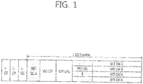
- FIG. 1 shows the structure of a data frame used in a data transmission/reception method according to an embodiment of the present invention.
- L-STF and L-LTF, training fields, and L-SIG, a signal field are the same as those of a data frame used in an existing 802.11.
- the frame illustrated in FIG. 1 further includes fields dedicated for high speed wireless communication, i.e., very high throughput (VHT).
- VHT-STF and VHT-LTF are VHT-dedicated training fields
- VHT-SIG A and VHT-SIG B are VHT-dedicated signal fields.
- the data frame of FIG. 1 includes data fields VHT-DATA including data transmitted to several users, respectively.
- VHT-SIG B includes information regarding each of the data fields.
- VHT-SIG B may include information regarding the length of useful data included in the VHT-DATA field, information regarding a modulation and coding scheme (MCS) of the VHT-DATA field, and the like. Since the VHT-SIG B field includes information regarding each user, it corresponds to a dedicated signal field. Meanwhile, the VHT-SIG A field is a common signal field transmitted to be recognized by every user.
- MCS modulation and coding scheme
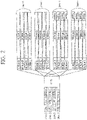
- FIG. 2 shows an embodiment in which an access point (AP) transmits four streams through MU-MIMO beamforming by using four antennas in an 80 MHz frequency band and two stations (STA) receive the streams by using two antennas, respectively.
- AP access point
- STA stations
- VHT-SIG A field a common signal field, is iterated four times so as to be transmitted as one stream, and MU-MIMO is not applied to this transmission.
- the presence of the L-SIG field in front of VHT-SIG A field is to maintain backward compatibility with existing legacy equipment.
- a VHT-TF field is used to perform channel estimation in using MU-MIMO beamforming, and may have a resolvable or non-resolvable form.
- VHT-SIG A includes common information commonly applied to two stations (STA). Also, VHT-SIG A, having a different structure from a signal field generated in legacy equipment, is used for auto-detection of VHT equipment. Here, VHT-SIG A is simply iteratively transmitted in units of 20 MHz frequency, whereby both an SNR gain and a frequency diversity gain can be obtained.
- VHT-SIG B a dedicated-signal field, including information applied to each of the stations STA.
- VHT-SIG B is not required to be transmitted by using the simple iterative structure like the VHT-SIG A does.
- VHT-SIG B cannot obtain both an SNR gain and a frequency diversity gain.
- the present invention provides a method, apparatus, and a data field configuration capable of enhancing transmission efficiency by using a new method, rather than the simple iterative method like the existing VHT-SIG A field in transmitting the VHG-SIG B field.
- FIG 3 shows a structure of the VHT-SIG B field when a station (STA) receives one stream in a 20 MHz frequency band.
- the VHT-SIG B (referred to as an 'SIG B', hereinafter) is modulated according to BPSK and has one OFDM symbol.
- STA station
- FIG 3 since there is only one SIG B, it may be transmitted as it is.
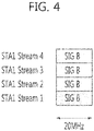
- FIG. 4 shows a structure of the VHT-SIG B field when a station (STA) receives four streams in a 20 MHz frequency band.
- STA station
- four SIG Bs are transmitted.
- the SIG B is transmitted in a simple iterative manner like the VHT-SIG A
- the iterative four bits are all placed in the same situation.
- an SNR gain according to the iteration four times may be obtained, but a frequency diversity effect cannot be obtained.
- different interleaving is applied to the SIG Bs of the stream 1 to stream 4.
- the same bits of a coded codeword of the SIG Bs is included in a different subcarrier of a different stream and transmitted, both the SNR gain and the frequency diversity gain can be obtained, improving transmission performance.
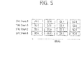
- FIG. 5 shows a structure of the VHT-SIG B field when a station (STA) receives four streams in an 80 MHz frequency band.
- STA station
- FIG. 5 shows a structure of the VHT-SIG B field when a station (STA) receives four streams in an 80 MHz frequency band.
- SIG B is simply iterated in a frequency band, both the SNR gain and the frequency diversity gain can be obtained.
- maximum performance can be obtained by simply iterating the scheme applied to the four streams in the embodiment of FIG. 4 .
- the method described with reference to FIGS. 4 and 5 may be applied in the same manner to 40 MHz frequency band or 160 MHz band and when the number of streams is two or three.
- VHT-SIG B field information included in the VHT-SIG B field is required to be stably transmitted compared with information included in the VHT-DATA field.
- the VHT-SIG B field is transmitted by using a BPSK modulation and a low coding rate, or the like, thus being protected.
- the method described with reference to FIGS. 4 and 5 may protect the VHT-SIG B more than necessary.
- VHT-SIG A In the case of VHT-SIG A, it must be necessarily recognized in units of 20 MHz at a receiver (or a receiving end). Thus, the VHT-SIG A must be iteratively transmitted by a corresponding symbol length regardless of the number of symbols. However, iteratively transmitting the VHT-SIG B by a corresponding symbol length may be problematic in terms of the foregoing transmission performance and efficiency.
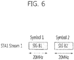
- FIG 6 shows a structure of the VHT-SIG B field having two symbols when a station (STA) receives one stream in a 20 MHz frequency band.
- the SIG B is modulated according to BPSK and has two OFDM symbols.
- it since there is only one SIG B, it may be transmitted as it is.
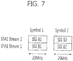
- FIG. 7 shows a structure of a VHT-SIG B field having two symbols when a station (STA) receives four streams in a 20 MHz frequency band.
- STA station
- both SNR gain and frequency diversity gain can be obtained by applying different interleaving to streams.
- the method of FIG. 7 may not be an effective transmission because the SIG B is transmitted over two symbols. Thus, the following transmission method is considered.
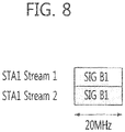
- FIG. 8 shows a structure of the VHT-SIG B field having one symbol when a station (STA) receives four streams in a 20 MHz frequency band.
- the SIG B information which has occupied two symbols when transmitted as one stream in the 20 MHz frequency band, can be effectively transmitted by only one symbol.
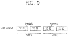
- FIG. 9 shows an embodiment in which SIG Bs are transmitted over two symbols in a similar manner to that of a VHT-SIG A when a station (STA) receives one stream in a 40 MHz frequency band.
- STA station
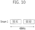
- FIG. 10 shows a structure of the VHT-SIG B field having one symbol when a station (STA) receives one stream in a 40 MHz frequency band.
- STA station
- the SIG B information which has occupied two symbols when transmitted as one stream in the 40 MHz frequency band, can be effectively transmitted through one symbol.
- the VHT-SIG B when the VHT-SIG B has two symbols when transmitted as one stream in the 20 MHz frequency band, even though the number of streams is increased or the frequency band extends, the VHT-SIG B can be effectively transmitted by using one symbol. Also, the foregoing methods may extend as follows.
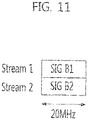
- FIG 11 shows an embodiment of applying the data transmission method according to the present invention to a case in which a station (STA) receives two streams in a 20 MHz frequency band.
- FIG. 12 shows an embodiment of applying the data transmission method according to the present invention to a case in which a station (STA) receives three streams in a 20 MHz frequency band.
- stream 3 is configured of B1 corresponding to an even number bit of a codeword of the SIG B1 and B2 corresponding to an odd number bit of a codeword of SIG B2.
- the stream 3 transmitted thusly may be combined at a receiver.
- FIG. 13 shows an embodiment of applying the data transmission method according to the present invention to a case in which a station (STA) receives four streams in a 20 MHz frequency band.
- SIG B1 is iterated in streams 1 and 3
- SIG B2 is iterated in streams 2 and 4.
- a simple iteration cannot obtain a frequency diversity gain, so different interleaving may be applied to each stream in order to enhance transmission performance as mentioned above.
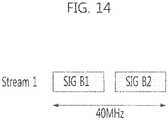
- FIG 14 shows an embodiment of applying the data transmission method according to the present invention to a case in which a station (STA) receives one stream in a 40 MHz frequency band.
- FIG. 15 shows an embodiment of applying the data transmission method according to the present invention to a case in which a station (STA) receives two streams in a 40 MHz frequency band.
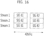
- FIG. 16 shows an embodiment of applying the data transmission method according to the present invention to a case in which a station (STA) receives three streams in a 40 MHz frequency band.
- Different interleaving may be applied to each stream of FIGS. 14 , 15 , and 16 .
- FIG. 17 shows an embodiment of applying the data transmission method according to the present invention to a case in which a station (STA) receives one stream in an 80 MHz frequency band.
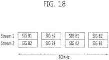
- FIG. 18 shows an embodiment of applying the data transmission method according to the present invention to a case in which a station (STA) receives two streams in an 80 MHz frequency band.
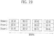
- FIG. 19 shows an embodiment of applying the data transmission method according to the present invention to a case in which a station (STA) receives three streams in an 80 MHz frequency band.
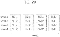
- FIG. 20 shows an embodiment of applying the data transmission method according to the present invention to a case in which a station (STA) receives four streams in an 80 MHz frequency band.
- Different interleaving may be applied to each stream of FIGS. 17 , 18 , 19 , and 20 .
- FIG. 21 shows an embodiment of applying the data transmission method according to the present invention to a case in which a station (STA) receives one stream in a 160 MHz frequency band.
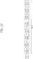
- FIG. 22 shows an embodiment of applying the data transmission method according to the present invention to a case in which a station (STA) receives two streams in a 160 MHz frequency band.
- FIG. 23 shows an embodiment of applying the data transmission method according to the present invention to a case in which a station (STA) receives three streams in a 160 MHz frequency band.
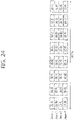
- FIG. 24 shows an embodiment of applying the data transmission method according to the present invention to a case in which a station (STA) receives four streams in a 160 MHz frequency band.
- Different interleaving may be applied to each stream of FIGS. 21 , 22 , 23 , and 24 .
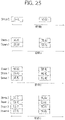
- FIG. 25 shows an embodiment of applying the data transmission method according to the present invention to a case in which data is transmitted via two non-contiguous multi-channels in an 80 MHz frequency band.
- FIG. 26 shows an embodiment of applying the data transmission method according to the present invention to a case in which data is transmitted via three non-contiguous multi-channels in an 80 MHz frequency band. Different interleaving may be applied to each stream of FIGS. 25 and 26 .
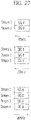
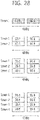
- FIG. 27 shows an embodiment of applying the data transmission method according to the present invention to a case in which data is transmitted by using one QPSK symbol in a 20 MHz frequency band.
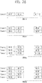
- FIG. 28 shows an embodiment of applying the data transmission method according to the present invention to a case in which data is transmitted by using one QPSK symbol in a 40 MHz frequency band.
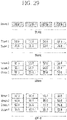
- FIG. 29 shows an embodiment of applying the data transmission method according to the present invention to a case in which data is transmitted by using one QPSK symbol in an 80 MHz frequency band.
- FIG. 30 shows an embodiment of applying the data transmission method according to the present invention to a case in which data is transmitted via two non-contiguous multi-channels by using one QPSK symbol in an 80 MHz frequency band.
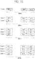
- FIG. 31 shows an embodiment of applying the data transmission method according to the present invention to a case in which data is transmitted via three non-contiguous multi-channels by using one QPSK symbol in an 80 MHz frequency band.
- Different interleaving may be applied to each stream of FIGS. 27 , 28 , 29 , 30 , and 31 .
- the transmission method according to an embodiment of the present invention as described above can be applicable when one stream is transmitted as a space-time block code (STBC) (or an Alamouti code) through two antennas.
- STBC space-time block code
- the VHT-SIG B field may be transmitted as the STBC in the same manner as that of the data field, or the VHT-SIG B field may be transmitted by using one of two space-time streams.
- STBC-related information should be included in the VHT-SIG A in advance and transmitted, and in the latter case, the STBC-related information may be included in the VHT-SIG B and transmitted.
- FIG. 32 shows an embodiment of applying the data transmission method according to the present invention to a case in which a first stream is transmitted by using two space-time streams and a second stream is transmitted as it is in a 20 MHz frequency band.
- FIG. 33 shows an embodiment of applying a data transmission method according to the present invention to a case in which a first stream is transmitted by using two space-time streams and a second stream is transmitted as it is in a 40 MHz frequency band.
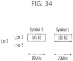
- FIG. 34 shows an embodiment of applying the data transmission method according to the present invention to a case in which one stream is transmitted by using two space-time streams in a 20 MHz frequency band.
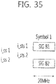
- FIG. 35 shows an embodiment of applying the data transmission method according to the present invention to a case in which a first stream is transmitted by using two space-time streams and a second stream is transmitted as it is in a 20 MHz frequency band.
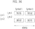
- FIG 36 shows an embodiment of applying the data transmission method according to the present invention to a case in which a first stream is transmitted by using two space-time streams and a second stream is transmitted as it is in a 40 MHz frequency band.
- the streams can be effectively transmitted by using one symbol.
- the data transmission method according to an embodiment of the present invention as described above may also be applicable when only a portion of a stream is transmitted by using the STBC.
- the data transmission method according to an embodiment of the present invention as described above may also be applicable when the VHT-SIG B uses three or more OFDM symbols in transmitting one stream in a 20 MHz band.
- a dedicated signal field is iteratively effectively transmitted in a frequency or stream domain, to thus obtain a maximum diversity gain.
- This method can be applicable to a case in which a frame is transmitted by using channel bonding in a 40 MHz or 80 MHz bandwidth.
- a portion of a frequency tone which is generally used as a guard band, or the like, can be used as a frequency tone for a data transmission.
- the number of data transmission frequency tones in the 20 MHz band is 52
- the number of data transmission frequency tones in the 40 MHz band is 108.
- the use of channel bonding results in an increase in the number of four data transmission frequency tones in the 40 MHz band.
- the number of transmission frequency tones can be further increased in an 80 MHz band by using channel bonding based on the same principle.
- the foregoing VHT-SIG B field transmission scheme of the present invention can be applicable to a frame transmission using channel bonding.
- the increased data transmission frequency tones can be used to increase the amount of data included in a signal field or the iteration number of signal fields.
- the method according to the present invention can be applicable even to a case in which the number of bits of the SIG B in the 40 MHz band or the 80 MHz band is greater than the number of bits of the SIG B in the 20 MHz band.
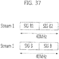
- FIG. 37 shows an embodiment of applying the data transmission method according to the present invention to a case in which a station (STA) receives one stream in a 40 MHz frequency band.
- FIG 38 shows an embodiment of applying the data transmission method according to the present invention to a case in which a station (STA) receives two streams in a 40 MHz frequency band.
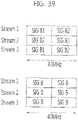
- FIG. 39 shows an embodiment of applying the data transmission method according to the present invention to a case in which a station (STA) receives three streams in a 40 MHz frequency band.
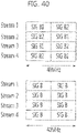
- FIG 40 shows an embodiment of applying the data transmission method according to the present invention to a case in which a station (STA) receives four streams in a 40 MHz frequency band.
- Different interleaving may be applied to each stream of FIGS. 37 , 38 , 39 , and 40 .
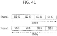
- FIG. 41 shows an embodiment of applying the data transmission method according to the present invention to a case in which a station (STA) receives one stream in an 80 MHz frequency band.
- FIG. 42 shows an embodiment of applying the data transmission method according to the present invention to a case in which a station (STA) receives two streams in an 80 MHz frequency band.
- FIG 43 shows an embodiment of applying the data transmission method according to the present invention to a case in which a station (STA) receives three streams in an 80 MHz frequency band.
- FIG. 44 shows an embodiment of applying the data transmission method according to the present invention to a case in which a station (STA) receives four streams in an 80 MHz frequency band.
- Different interleaving maybe applied to each stream of FIGS. 41 , 42 , 43 , and 44 .
- the number of bits of the SIG B and the number of frequency tones used in transmission are not in a mutually multiple relationship, some frequency tones may remain after iterating the SIG B.
- a method of iterating only a portion of the SIG B or padding may be used. This method can be applicable when the information of SIG B is increased according to an increase in the frequency bandwidth from 20 MHz to 40 MHz and to 80 MHz.
- the frequency bandwidth when the frequency bandwidth is increased, the amount of data transmitted in the same duration is increased. Accordingly, when length information of transmitted data, or the like, is included in the VHT-SIG B and transmitted, the length of the VHT-SIG B itself is increased.
- a bit allocation of the VHT-SIG B is changed by frequency bandwidth and the VHT-SIG B may be iterated according to the number of transmittable frequency tones, thus enhancing transmission efficiency. For example, it is assumed that the number of available data tones in a 20 MHz band is 26 bits, the number of available data tones in a 40 MHz band is 54 bits, and the number of available data tones in an 80 MHz band is 117 bits. In this case, the length of the VHT-SIG B is 26 bits in the 20 MHz band, 27 bits in the 40 MHz band, and 29 bits in the 80 MHz band.
- FIG. 45 shows a bit allocation in this case.
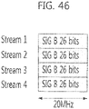
- FIG. 46 shows an embodiment of applying the data transmission method according to the present invention to a case in which a station (STA) receives four streams in a 20 MHz frequency band, when the numbers of bits of the VHT-SIG B are allocated as shown in FIG. 45 .
- FIG 47 shows an embodiment of applying the data transmission method according to the present invention to a case in which a station (STA) receives four streams in a 40 MHz frequency band, when the numbers of bits of the VHT-SIG B are allocated as shown in FIG. 45 .
- FIG. 46 shows an embodiment of applying the data transmission method according to the present invention to a case in which a station (STA) receives four streams in a 40 MHz frequency band, when the numbers of bits of the VHT-SIG B are allocated as shown in FIG. 45 .
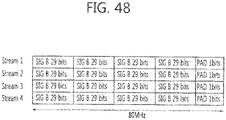
- FIG. 48 shows an embodiment of applying the data transmission method according to the present invention to a case in which a station (STA) receives four streams in an 80 MHz frequency band, when the numbers of bits of the VHT-SIG B are allocated as shown in FIG. 45 .
- STA station
- Different interleaving may be applied to each stream of FIGS. 46 , 47 , and 48 .
- the present invention can be applicable even when the number of transmitted streams is changed in the embodiments of FIGS. 46 , 47 , and 48 .
- the bit allocation of VHT-SIG B in FIG. 45 includes tail bits for a convolutional code.
- the VHT-SIG B of FIG 45 does not include CRC bits for determining whether or not a codeword has an error, making it difficult to obtain reliability of data.
- some (4 to 8 bits) of the reserved bits included in a service field of a data field may be used as the CRC bit as shown in FIG 49 .
- the CRC is simultaneously applied to the SIG B and a scrambler seed.
- CRC calculation with respect to a variable length is required for each frequency band.
- the VHT-SIG B field uses a low modulations scheme and coding rate (BPSK 1/2), and is available for an iterative coding to frequency and an antenna domain, so it has high reliability.
- the service field uses the modulation scheme and coding rate used for transmission of data, as it is, so its reliability is relatively variable and generally has low reliability compared with the VHT-SIG B.
- the use of a CRC can detect an error of information included in the VHT-SIG B field and an error of a scrambler seed.
- the operation of PHY and MAC layers can be stopped, obtaining an effect of reducing power consumption.
- the foregoing method can be applicable to SU-MIMO.
- the VHT-SIG A may relatively have extra bits.
- the MCS bits, which are included in the VHT-SIG B field can be included in the VHT-SIG A field.
- the number of antennas in use may be increased, so the number of bits of the field indicating a data length may be increased.
- FIG. 50 shows a bit allocation of the VHT-SIG B when the VHT-SIG B has a length of 26 bits in a 20 MHz band, 27 bits in a 40 MHz band, and 29 bits in a 80 MHz band in SU-MIMO.
- FIG. 51 shows an embodiment of applying a data transmission method according to the present invention to a case in which a station (STA) receives four streams in a 20 MHz frequency band, when the numbers of bits of the VHT-SIG B are allocated as shown in FIG. 50 .
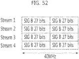
- FIG. 52 shows an embodiment of applying a data transmission method according to the present invention to a case in which a station (STA) receives four streams in a 40 MHz frequency band, when the numbers of bits of the VHT-SIG B are allocated as shown in FIG. 50 .
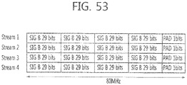
- FIG 53 shows an embodiment of applying a data transmission method according to the present invention to a case in which a station (STA) receives four streams in an 80 MHz frequency band, when the numbers of bits of the VHT-SIG B are allocated as shown in FIG. 50 .
- STA station
- Different interleaving may be applied to each stream of FIGS. 51 , 52 , and 53 .
- the present invention can be applicable even when the number of transmitted streams is changed in the embodiments of FIGS. 51 , 52 , and 53 .
- the VHT-SIG B field includes tail bits for a convolutional code.
- the VHT-SIG B of FIG. 50 does not include a CRC bits for determining whether or not a codeword has an error, making it difficult to obtain reliability of data.
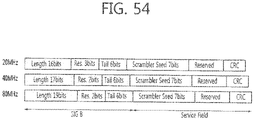
- some (4 to 8 bits) of the reserved bits included in a service field of a data field may be used as the CRC bit as shown in FIG. 54 .
- the CRC is simultaneously applied to the SIG B and a scrambler seed.
- CRC calculation with respect to a variable length is required for each frequency band.
- the VHT-SIG B field uses a low modulations scheme and coding rate (BPSK 1/2), and is available for an iterative coding to frequency and an antenna domain, so it has high reliability.
- the service field uses the modulation scheme and coding rate used for transmission of data, as it is, so its reliability is relatively variable and generally has low reliability compared with the VHT-SIG B.
- the use of a CRC can detect an error of information included in the VHT-SIG B field and an error of a scrambler seed.
- the operation of PHY and MAC layers can be stopped, obtaining an effect of reducing power consumption.
- cyclic delay diversity (CDD) technique may be used to transmit the VHT-SIG B field, without applying different interleaving to each transmission stream.
- CDD cyclic delay diversity
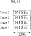
- FIG. 55 shows an embodiment of applying the data transmission method according to the present invention to a case in which a station (STA) receives four streams in a 20 MHz frequency band, when cyclic delay diversity (CDD) technique is used and different delay is applied to each antenna.
- FIG. 56 shows an embodiment of applying the data transmission method according to the present invention to a case in which a station (STA) receives four streams in a 40 MHz frequency band, when a CDD technique is used and different delay is applied to each antenna.
- FIG. 57 shows an embodiment of applying the data transmission method according to the present invention to a case in which a station (STA) receives four streams in an 80 MHz frequency band, when a CDD technique is used and different delay is applied to each antenna. Different delay is applied to each stream of FIGS. 55 , 56 , and 57 .
- the present invention can be applicable even when the number of transmitted streams is changed in the embodiments of FIGS. 55 , 56 , and 57 .
- spreading matrix to the antenna domain having a size of may be additionally applicable to the VHT-SIG B transmission scheme of the present invention.
- the spreading matrix when multi-stream is applied can be applicable, and when each stream is transmitted by applying delay thereto, the spreading matrix when a single stream is applied can be applicable.
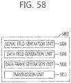
- FIG. 58 shows the configuration of a transmission terminal according to an embodiment of the present invention.
- a transmission terminal 5802 includes a signal field generation unit 5804, a data field generation unit 5806, a data frame generation unit 5808, and a transmission unit 5810.
- the signal field generation unit 5804 iteratively generates a signal field according to a frequency band applied to transmission of a data frame.
- the data field generation unit 5806 generates a data field including data to be transmitted to a reception terminal.
- the data frame generation unit 5808 generates a data frame including the signal field generated by the signal field generation unit 5804 and the data field generated by the data field generation unit 5806.
- the transmission unit 5810 transmits the data frame generated by the data frame generation unit 5808 to the reception terminal.
- the signal field may include a length field indicating the length of a data field, and the length field may have a length which differs according to a frequency band applied to transmission of a data frame.
- the signal field may include a modulation and coding scheme (MCS) field indicating a modulation method and a coding method of the data field.
- MCS modulation and coding scheme
- the signal field may be a dedicated signal field for transferring information regarding each user.
- the data frame may include a cyclic redundancy check (CRC) field for detecting an error of the signal field.
- CRC cyclic redundancy check
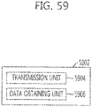
- FIG 59 shows the configuration of a reception terminal according to an embodiment of the present invention.
- a reception terminal 5902 includes a reception unit 5904 and a data obtaining unit 5906.
- the reception unit 5904 receives a data frame including a signal field and a data field.
- the signal field may include a length field indicating the length of a data field, and the length field may have a length which differs according to a frequency band applied to transmission of a data frame.
- the signal field may include a modulation and coding scheme (MCS) field indicating a modulation method and a coding method of the data field.
- MCS modulation and coding scheme
- the signal field may be a dedicated signal field for transferring information regarding each user.
- the data frame may include a cyclic redundancy check (CRC) field for detecting an error of the signal field.
- CRC cyclic redundancy check
- the data obtaining unit 5906 obtains data included in the data field by using the signal field included in the received data frame.
- the data obtaining unit 5906 may obtain the data by using the length field, the MCS field, or the like, included in the signal field.
- the data obtaining unit 5906 may detect an error of the signal field by using the CRC field included in the data frame.
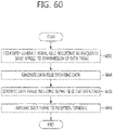
- FIG. 60 is a flow chart illustrating the process of a method for transmitting data by a transmission terminal according to an embodiment of the present invention.
- a signal field is iteratively generated according to a frequency band applied to transmission of a data frame (6002). Also, a data field including data to be transmitted to a reception terminal is generated (6004). And then, a data frame including the generated signal field and data field is generated (6006). Thereafter, the generated data frame is transmitted to a reception terminal (6008).
- the signal field may include a length field indicating the length of the data field, and the length field may have a length which differs according to a frequency band applied to transmission of the data frame.
- the signal field may include a modulation and coding scheme (MCS) field indicating a modulation method and a coding method of the data field.
- MCS modulation and coding scheme
- the signal field may be a dedicated signal field for transferring information regarding each user.
- the data frame may include a cyclic redundancy check (CRC) field for detecting an error of the signal field.
- CRC cyclic redundancy check
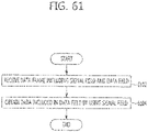
- FIG. 61 is a flow chart illustrating the process of a method for receiving data by a reception terminal according to an embodiment of the present invention.
- a data frame including a signal field and a data field is received (6102).
- the signal field may include a length field indicating the length of the data field, and the length field may have a length which differs according to a frequency band applied to transmission of the data frame.
- the signal field may include a modulation and coding scheme (MCS) field indicating a modulation method and a coding method of the data field.
- MCS modulation and coding scheme
- the signal field may be a dedicated signal field for transferring information regarding each user.
- the data frame may include a cyclic redundancy check (CRC) field for detecting an error of the signal field.
- CRC cyclic redundancy check
- data included in the data field is obtained by using the signal field included in the received data frame (6104).
- the reception terminal may obtain data by using the length field, the MCS field, or the like, included in the signal field. Also, the reception terminal may detect an error of the signal field by using a CRC field included in the data frame.
- the performance of the signal field is enhanced and a transmission time is reduced by utilizing the user frequency band and the number of streams, whereby a large amount of information can be effectively transmitted by using the signal field.
Landscapes
- Engineering & Computer Science (AREA)
- Signal Processing (AREA)
- Computer Networks & Wireless Communication (AREA)
- Radio Transmission System (AREA)
- Mobile Radio Communication Systems (AREA)
Claims (9)
- Verfahren für ein drahtloses Nahbereichsnetz, wobei das Verfahren umfasst:Empfangen durch einen Empfänger eines Datenrahmens, der ein Signalfeld und ein Datenfeld enthält, wobei ein Signalfeld mehrere "Very High Throughput Signal A"-Felder (VHT-SIG-A-Felder) und ein "Very High Throughput Signal B"-Feld (VHT-SIG-B-Feld) enthält, wobei die mehreren VHT-SIG-A-Felder und das VHT-SIG-B-Feld auf einem Betriebsband empfangen werden, wobei das Betriebsband mehrere 20 MHz-Bänder umfasst;Erhalten von Daten von dem Datenfeld anhand des VHT-SIG-B-Feldes, wobei:
das VHT-SIG-B-Feld über die gesamte Bandbreite in einem OFDM-Symbol nach den mehr als einem OFDM-Symbol, in denen die mehreren VHT-SIG-A-Felder gesendet werden, gesendet wird; dadurch gekennzeichnet, dass:die mehreren VHT-SIG-A-Felder ein erstes VHT-SIG-A-Feld und ein zweites VHT-SIG-A-Feld enthalten;das erste VHT-SIG-A-Feld auf einem ersten 20 MHz-Band unter den mehreren 20 MHz-Bändern gesendet wird;das zweite VHT-SIG-A-Feld auf einem zweiten 20 MHz-Band unter den mehreren 20 MHz-Bändern gesendet wird;das VHT-SIG-B-Feld einen ersten Teil von Bits umfasst, wobei der erste Teil von Bits in dem VHT-SIG-B-Feld wiederholt wird;der erste Teil von Bits einen Längenindikator umfasst, der sich auf eine Länge des Datenfeldes bezieht;eine Anzahl von Wiederholungen des ersten Teils von Bits anhand der Bandbreite des Betriebsbandes bestimmt wird, wobei sich die Anzahl von Wiederholungen erhöht, wenn die Bandbreite des Betriebsbandes zunimmt;undeine erste Anzahl von Bits, die den Längenindikator repräsentieren, wenn das Betriebsband 40 MHz ist, 2 Bits kürzer als eine zweite Anzahl von Bits ist, die den Längenindikator repräsentieren, wenn das Betriebsband gleich 80 MHz ist. - Verfahren nach Anspruch 1, wobei der erste Teil von Bits aus 27 Bits besteht und die erste Anzahl von Bits, die den Längenindikator repräsentieren, 17 ist, wenn die Bandbreite des Betriebsbandes 40 MHz ist.
- Verfahren nach Anspruch 1, wobei der erste Teil von Bits aus 29 Bits besteht und die zweite Anzahl von Bits, die den Längenindikator repräsentieren, 19 ist, wenn die Bandbreite des Betriebsbandes gleich 80 MHz ist.
- Verfahren nach Anspruch 1, das ferner umfasst:
Empfangen eines Datenfeldes, wobei das Datenfeld ein Feld einer zyklischen Redundanzüberprüfung (CRC-Feld) enthält, das verwendet wird, um einen Fehler des VHT-SIG-B-Feldes zu detektieren. - Drahtlose Kommunikationsvorrichtung, die umfasst:einen Prozessor; undeinen Speicher, der an den Prozessor betriebstechnisch gekoppelt ist und Anweisungen speichert, die dann, wenn sie durch den Prozessor ausgeführt werden,einen Datenrahmen empfangen, der ein Signalfeld und ein Datenfeld enthält, wobei ein Signalfeld mehrere "Very High Throughput Signal A"-Felder (VHT-SIG-A-Felder) und ein "Very High Throughput Signal B"-Feld (VHT-SIG-B-Feld) enthält, wobei die mehreren VHT-SIG-A-Felder und das VHT-SIG-B-Feld auf einem Betriebsband empfangen werden, wobei das Betriebsband mehrere 20 MHz-Bänder umfasst;Daten von dem Datenfeld anhand des VHT-SIG-B-Feldes erhalten, wobei:
das VHT-SIG-B-Feld über die gesamte Bandbreite in einem OFDM-Symbol nach den mehr als einem OFDM-Symbol, in denen die mehreren VHT-SIG-A-Felder gesendet werden, gesendet wird; dadurch gekennzeichnet, dass:die mehreren VHT-SIG-A-Felder ein erstes VHT-SIG-A-Feld und ein zweites VHT-SIG-A-Feld enthalten;das erste VHT-SIG-A-Feld auf einem ersten 20 MHz-Band unter den mehreren 20 MHz-Bändern gesendet wird;das zweite VHT-SIG-A-Feld auf einem zweiten 20 MHz-Band unter den mehreren 20 MHz-Bändern gesendet wird;das VHT-SIG-B-Feld einen ersten Teil von Bits umfasst, wobei der erste Teil von Bits in dem VHT-SIG-B-Feld wiederholt wird;der erste Teil von Bits einen Längenindikator umfasst, der sich auf eine Länge des Datenfeldes bezieht;eine Anzahl von Wiederholungen des ersten Teils von Bits anhand der Bandbreite des Betriebsbandes bestimmt wird, wobei sich die Anzahl von Wiederholungen erhöht, wenn die Bandbreite des Betriebsbandes zunimmt;undeine erste Anzahl von Bits, die den Längenindikator repräsentieren, wenn das Betriebsband 40 MHz ist, 2 Bits kürzer als eine zweite Anzahl von Bits ist, die den Längenindikator repräsentieren, wenn das Betriebsband gleich 80 MHz ist. - Vorrichtung nach Anspruch 5, wobei das VHT-SIG-A-Feld erste Informationen enthält, die allen der mehreren Empfänger gemeinsam sind, und das VHT-SIG-B-Feld zweite Informationen enthält, die für den Empfänger spezifisch sind.
- Vorrichtung nach Anspruch 5, wobei:der erste Teil von Bits einen Index bezüglich eines Modulations- und Codierschemas (MCS), den Längenindikator und Endbits enthält; undder Index bezüglich des MCS 4 Bits lang ist, die Endbits 6 Bits lang sind und der Längenindikator kürzer als 20 Bits ist.
- Vorrichtung nach Anspruch 5, wobei der erste Teil von Bits aus 27 Bits besteht und die erste Anzahl von Bits, die den Längenindikator repräsentieren, 17 ist, wenn die Bandbreite des Betriebsbandes 40 MHz ist.
- Vorrichtung nach Anspruch 5, wobei der erste Teil von Bits aus 29 Bits besteht und die zweite Anzahl von Bits, die den Längenindikator repräsentieren, 19 ist, wenn die Bandbreite des Betriebsbandes gleich 80 MHz ist.
Priority Applications (2)
| Application Number | Priority Date | Filing Date | Title |
|---|---|---|---|
| EP25174014.8A EP4586526A3 (de) | 2010-03-12 | 2011-03-11 | Verfahren und vorrichtung zum senden und empfangen von daten in einem mimo-system |
| EP22152196.6A EP4020830B1 (de) | 2010-03-12 | 2011-03-11 | Verfahren und Vorrichtung zum Senden nd Empfangen von Daten in einem MIMO-System |
Applications Claiming Priority (8)
| Application Number | Priority Date | Filing Date | Title |
|---|---|---|---|
| KR20100022122 | 2010-03-12 | ||
| KR20100065898 | 2010-07-08 | ||
| KR20100066458 | 2010-07-09 | ||
| KR20100068167 | 2010-07-14 | ||
| KR20100072506 | 2010-07-27 | ||
| PCT/KR2011/001742 WO2011112054A2 (ko) | 2010-03-12 | 2011-03-11 | Mimo 시스템에서 데이터를 송수신하는 방법 및 장치 |
| EP11753658.1A EP2547002B1 (de) | 2010-03-12 | 2011-03-11 | Verfahren und vorrichtung zum senden und empfangen von daten in einem mimo-system |
| EP14199757.7A EP2911313B1 (de) | 2010-03-12 | 2011-03-11 | Verfahren und Vorrichtung zum Senden und Empfangen von Daten in einem MIMO-System |
Related Parent Applications (3)
| Application Number | Title | Priority Date | Filing Date |
|---|---|---|---|
| EP14199757.7A Division EP2911313B1 (de) | 2010-03-12 | 2011-03-11 | Verfahren und Vorrichtung zum Senden und Empfangen von Daten in einem MIMO-System |
| EP14199757.7A Division-Into EP2911313B1 (de) | 2010-03-12 | 2011-03-11 | Verfahren und Vorrichtung zum Senden und Empfangen von Daten in einem MIMO-System |
| EP11753658.1A Division EP2547002B1 (de) | 2010-03-12 | 2011-03-11 | Verfahren und vorrichtung zum senden und empfangen von daten in einem mimo-system |
Related Child Applications (3)
| Application Number | Title | Priority Date | Filing Date |
|---|---|---|---|
| EP22152196.6A Division-Into EP4020830B1 (de) | 2010-03-12 | 2011-03-11 | Verfahren und Vorrichtung zum Senden nd Empfangen von Daten in einem MIMO-System |
| EP22152196.6A Division EP4020830B1 (de) | 2010-03-12 | 2011-03-11 | Verfahren und Vorrichtung zum Senden nd Empfangen von Daten in einem MIMO-System |
| EP25174014.8A Division EP4586526A3 (de) | 2010-03-12 | 2011-03-11 | Verfahren und vorrichtung zum senden und empfangen von daten in einem mimo-system |
Publications (2)
| Publication Number | Publication Date |
|---|---|
| EP3393053A1 EP3393053A1 (de) | 2018-10-24 |
| EP3393053B1 true EP3393053B1 (de) | 2022-05-11 |
Family
ID=44564033
Family Applications (5)
| Application Number | Title | Priority Date | Filing Date |
|---|---|---|---|
| EP14199757.7A Active EP2911313B1 (de) | 2010-03-12 | 2011-03-11 | Verfahren und Vorrichtung zum Senden und Empfangen von Daten in einem MIMO-System |
| EP22152196.6A Active EP4020830B1 (de) | 2010-03-12 | 2011-03-11 | Verfahren und Vorrichtung zum Senden nd Empfangen von Daten in einem MIMO-System |
| EP11753658.1A Active EP2547002B1 (de) | 2010-03-12 | 2011-03-11 | Verfahren und vorrichtung zum senden und empfangen von daten in einem mimo-system |
| EP18170742.3A Active EP3393053B1 (de) | 2010-03-12 | 2011-03-11 | Verfahren und vorrichtung zum senden und empfangen von daten in einem mimo-system |
| EP25174014.8A Pending EP4586526A3 (de) | 2010-03-12 | 2011-03-11 | Verfahren und vorrichtung zum senden und empfangen von daten in einem mimo-system |
Family Applications Before (3)
| Application Number | Title | Priority Date | Filing Date |
|---|---|---|---|
| EP14199757.7A Active EP2911313B1 (de) | 2010-03-12 | 2011-03-11 | Verfahren und Vorrichtung zum Senden und Empfangen von Daten in einem MIMO-System |
| EP22152196.6A Active EP4020830B1 (de) | 2010-03-12 | 2011-03-11 | Verfahren und Vorrichtung zum Senden nd Empfangen von Daten in einem MIMO-System |
| EP11753658.1A Active EP2547002B1 (de) | 2010-03-12 | 2011-03-11 | Verfahren und vorrichtung zum senden und empfangen von daten in einem mimo-system |
Family Applications After (1)
| Application Number | Title | Priority Date | Filing Date |
|---|---|---|---|
| EP25174014.8A Pending EP4586526A3 (de) | 2010-03-12 | 2011-03-11 | Verfahren und vorrichtung zum senden und empfangen von daten in einem mimo-system |
Country Status (13)
| Country | Link |
|---|---|
| US (7) | US8654881B2 (de) |
| EP (5) | EP2911313B1 (de) |
| JP (5) | JP2013522950A (de) |
| KR (1) | KR101202197B1 (de) |
| CN (2) | CN105227267B (de) |
| AU (1) | AU2011224961B2 (de) |
| BR (1) | BR112012022749B1 (de) |
| CA (1) | CA2792929C (de) |
| DE (1) | DE112011100890T5 (de) |
| ES (3) | ES2535604T3 (de) |
| MX (1) | MX2012010564A (de) |
| PL (3) | PL4020830T3 (de) |
| WO (1) | WO2011112054A2 (de) |
Families Citing this family (38)
| Publication number | Priority date | Publication date | Assignee | Title |
|---|---|---|---|---|
| JP2013522950A (ja) | 2010-03-12 | 2013-06-13 | エレクトロニクス アンド テレコミュニケーションズ リサーチ インスチチュート | Mimoシステムにおけるデータを送受信する方法及び装置 |
| US8718169B2 (en) * | 2010-06-15 | 2014-05-06 | Qualcomm Incorporated | Using a field format on a communication device |
| KR101883892B1 (ko) * | 2011-10-13 | 2018-08-01 | 한국전자통신연구원 | 통신 시스템에서 데이터 송수신 장치 및 방법 |
| KR102068282B1 (ko) * | 2012-06-13 | 2020-01-20 | 한국전자통신연구원 | 다중 대역폭을 지원하는 무선랜 시스템의 통신 방법 및 장치 |
| CA2877484C (en) | 2012-07-09 | 2017-09-19 | Lg Electronics Inc. | Method and apparatus for transreceiving operating channel information in wireless communication system |
| US20140254389A1 (en) * | 2013-03-05 | 2014-09-11 | Qualcomm Incorporated | Systems and methods for monitoring wireless communications |
| US10439773B2 (en) * | 2013-04-15 | 2019-10-08 | Qualcomm Incorporated | Systems and methods for backwards-compatible preamble formats for multiple access wireless communication |
| US9729285B2 (en) * | 2013-06-13 | 2017-08-08 | Avago Technologies General Ip (Singapore) Pte. Ltd | Flexible OFDMA packet structure for wireless communications |
| RU2665050C2 (ru) * | 2014-06-08 | 2018-08-28 | ЭлДжи ЭЛЕКТРОНИКС ИНК. | Способ многопользовательской передачи по восходящей линии связи в системе беспроводной lan и устройство для его осуществления |
| US20170222769A1 (en) * | 2014-08-26 | 2017-08-03 | Intel IP Corporation | Apparatus, method, and computer readable medium for transmitting a high-efficiency wireless local-area network signal field for small and large bandwidth allocations |
| US10075269B2 (en) | 2014-09-12 | 2018-09-11 | Lg Electronics Inc. | Method for transmitting data in WLAN system, and device for same |
| US9398571B2 (en) | 2014-09-12 | 2016-07-19 | Newracom, Inc. | System and method for packet information indication in communication systems |
| US9906391B2 (en) * | 2014-09-16 | 2018-02-27 | Qualcomm Incorporated | Methods and apparatus for packet acquisition in mixed-rate wireless communication networks |
| US20160087825A1 (en) * | 2014-09-19 | 2016-03-24 | Qualcomm Incorporated | Methods and apparatus for early detection of high efficiency wireless packets in wireless communication |
| US9974053B2 (en) * | 2014-10-09 | 2018-05-15 | Lg Electronics Inc. | Method and apparatus for allocating wireless resources according to resource allocation setting in WLAN |
| US9877323B1 (en) * | 2014-10-28 | 2018-01-23 | Newracom, Inc. | OFDMA mapping for clients with various bandwidths |
| DE102015115777B4 (de) * | 2014-10-29 | 2020-01-30 | Intel IP Corporation | Gerät, Verfahren und Computer-lesbares Medium für das Übertragen eines Hoch-Effizienz-Drahtlos-Lokalnetzwerk-Signalfeldes für schmale und grosse Bandbreiten-Zuweisungen |
| US10419233B2 (en) * | 2014-11-21 | 2019-09-17 | Telefonaktiebolaget Lm Ericsson (Publ) | Method and apparatus for multimedia broadcast multicast service transmission |
| US9954595B2 (en) * | 2014-11-25 | 2018-04-24 | Qualcomm Incorporated | Frame format for low latency channel bonding |
| JP6450005B2 (ja) * | 2014-12-02 | 2019-01-09 | エルジー エレクトロニクス インコーポレイティド | 無線lanシステムにおける広帯域フレームのリソース割当て方法及びそのための装置 |
| US20160204915A1 (en) | 2015-01-14 | 2016-07-14 | Xiaogang Chen | Apparatus, computer readable medium, and method for generating and receiving signal fields in a high efficiency wireless local-area network |
| WO2016126034A1 (en) * | 2015-02-02 | 2016-08-11 | Lg Electronics Inc. | Methods and apparatus for transmitting/receiving he-sig b |
| JP6484346B2 (ja) * | 2015-03-04 | 2019-03-20 | エルジー エレクトロニクス インコーポレイティド | 無線lanシステムにおける制御情報を含む無線フレーム伝送方法及びそのための装置 |
| WO2016159737A1 (ko) | 2015-04-03 | 2016-10-06 | 엘지전자 주식회사 | 무선랜 시스템에서 시그널 필드를 구성하는 방법 및 장치 |
| US10021695B2 (en) * | 2015-04-14 | 2018-07-10 | Qualcomm Incorporated | Apparatus and method for generating and transmitting data frames |
| US10779264B2 (en) * | 2015-05-06 | 2020-09-15 | Lg Electronics Inc. | Method for transmitting wireless frame including multiple signaling fields, and device therefor |
| US10057924B2 (en) * | 2015-05-27 | 2018-08-21 | Intel IP Corporation | High efficiency signal field in high efficiency wireless local area network |
| CN112491501B (zh) | 2015-06-03 | 2024-05-14 | 苹果公司 | 集合物理层协议数据单元的传输装置和传输方法 |
| EP3331209B1 (de) * | 2015-07-28 | 2022-06-01 | LG Electronics Inc. | Drahtloses rahmenübertragungsverfahren auf der basis von signalisierungsfeldsortierung jedes bandes und vorrichtung dafür |
| CN110601805B (zh) * | 2015-11-04 | 2021-11-16 | 松下知识产权经营株式会社 | 无线通信系统中的控制信令的通信装置和通信方法 |
| US11178661B2 (en) | 2016-02-04 | 2021-11-16 | Lg Electronics Inc. | Method and device for generating STF signals by means of binary sequence in wireless LAN system |
| EP4072091B1 (de) | 2016-05-12 | 2025-09-10 | Panasonic Intellectual Property Corporation of America | Vorrichtung und verfahren zur diversitätsübertragung in einem drahtloskommunikationssystem |
| US10356784B2 (en) * | 2016-06-14 | 2019-07-16 | Lg Electronics Inc. | Method and apparatus for constructing control field including information regarding resource unit in wireless local area network system |
| US10700793B2 (en) * | 2017-09-12 | 2020-06-30 | Astronics Aerosat | Information transfer using discrete-frequency signals and instantaneous frequency measurement |
| US11303504B2 (en) | 2020-06-09 | 2022-04-12 | T-Mobile Usa, Inc. | Data link error feedback signaling |
| CN113259348A (zh) * | 2021-05-12 | 2021-08-13 | 深圳信息职业技术学院 | 异构数据处理方法、装置、计算机设备及存储介质 |
| EP4360243A1 (de) * | 2021-06-25 | 2024-05-01 | InterDigital Patent Holdings, Inc. | Aktivierung einer verbesserten subkanalselektiven übertragung in wlan-systemen |
| US12634750B2 (en) * | 2021-07-19 | 2026-05-19 | Huawei Technologies Co., Ltd. | Error protection of data unit service field in wireless local area network transmissions |
Family Cites Families (52)
| Publication number | Priority date | Publication date | Assignee | Title |
|---|---|---|---|---|
| US5287556A (en) * | 1990-09-28 | 1994-02-15 | Motorola, Inc. | Interference reduction using an adaptive receiver filter, signal strength, and BER sensing |
| AU768016B2 (en) | 2000-07-05 | 2003-11-27 | Lg Electronics Inc. | Method of configuring transmission in mobile communication system |
| US7194009B2 (en) | 2001-04-14 | 2007-03-20 | John Wai Tsang Eng | Full-service broadband cable modem system |
| US7062703B1 (en) | 2003-07-28 | 2006-06-13 | Cisco Technology, Inc | Early detection of false start-of-packet triggers in a wireless network node |
| ES2714800T3 (es) * | 2004-01-08 | 2019-05-30 | Sony Corp | Dispositivos de comunicación inalámbrica |
| US7324605B2 (en) | 2004-01-12 | 2008-01-29 | Intel Corporation | High-throughput multicarrier communication systems and methods for exchanging channel state information |
| US7055086B2 (en) | 2004-04-06 | 2006-05-30 | Cisco Technology, Inc. | Method and apparatus for protecting parts of a packet in a wireless network |
| EP1592160B1 (de) | 2004-04-29 | 2008-03-26 | Matsushita Electric Industrial Co., Ltd. | Fehlerkodierung in einem Überrahmen für digitalen Hörfunk (DAB) |
| RU2372721C2 (ru) | 2004-06-16 | 2009-11-10 | Конинклейке Филипс Электроникс Н.В. | Распределенное резервирование ресурсов в беспроводной специальной сети |
| DE102004038834B4 (de) | 2004-08-10 | 2006-11-02 | Siemens Ag | Verfahren zum Erzeugen von Präambel- und Signalisierungsstrukturen in einem MIMO-OFDM-Übertragungssystem |
| TWI385943B (zh) | 2004-08-11 | 2013-02-11 | Interdigital Tech Corp | 改善系統性能之頻道發聲 |
| WO2006034577A1 (en) | 2004-09-30 | 2006-04-06 | Nortel Networks Limited | Channel sounding in ofdma system |
| US9385843B2 (en) | 2004-12-22 | 2016-07-05 | Qualcomm Incorporated | Method and apparatus for using multiple modulation schemes for a single packet |
| US7577438B2 (en) | 2005-04-25 | 2009-08-18 | Interdigital Technology Corporation | Method and system for efficient addressing and power savings in wireless systems |
| JP4316646B2 (ja) * | 2005-05-10 | 2009-08-19 | 三菱電機株式会社 | 端末制御装置及び無線lanシステム |
| JP2007081702A (ja) * | 2005-09-13 | 2007-03-29 | Toshiba Corp | 無線受信装置及び無線受信方法 |
| JP4583319B2 (ja) | 2006-02-08 | 2010-11-17 | 株式会社エヌ・ティ・ティ・ドコモ | 移動局及び基地局 |
| KR100924684B1 (ko) | 2006-07-18 | 2009-11-03 | 삼성전자주식회사 | 광대역 무선통신시스템에서 통신 장치 및 방법 |
| JP4378368B2 (ja) * | 2006-09-13 | 2009-12-02 | 京セラ株式会社 | 移動体通信システム、基地局装置、移動局装置、およびマルチキャリア通信方法 |
| US8306060B2 (en) | 2006-11-07 | 2012-11-06 | Samsung Electronics Co., Ltd. | System and method for wireless communication of uncompressed video having a composite frame format |
| ZA200905127B (en) | 2007-02-14 | 2010-09-29 | Ericsson Telefon Ab L M | Codeword to layer mapping in a system implementing HARQ |
| CN101136894B (zh) * | 2007-03-23 | 2012-11-28 | 中兴通讯股份有限公司 | 可扩展的ofdm及ofdma带宽分配的方法和系统 |
| US20090031185A1 (en) * | 2007-07-23 | 2009-01-29 | Texas Instruments Incorporated | Hybrid arq systems and methods for packet-based networks |
| US8503283B2 (en) * | 2008-06-12 | 2013-08-06 | Nokia Corporation | Channel access protocol for wireless communication |
| US8891350B2 (en) * | 2008-07-07 | 2014-11-18 | Mediatek Inc. | Method and apparatus of data transmission over guard sub-carriers in multi-carrier OFDM systems |
| CN101646198B (zh) * | 2008-08-07 | 2013-10-30 | 夏普株式会社 | LTE-Advanced系统下行链路的实现方法、基站和用户设备 |
| US8351519B2 (en) * | 2008-08-15 | 2013-01-08 | Qualcomm Incorporated | Embedding information in an 802.11 signal field |
| US8295395B2 (en) | 2008-09-30 | 2012-10-23 | Apple Inc. | Methods and apparatus for partial interference reduction within wireless networks |
| US8665691B2 (en) | 2009-02-05 | 2014-03-04 | Sony Corporation | Frame and data pattern structure for multi-carrier systems |
| CN102396186B (zh) * | 2009-04-13 | 2014-12-10 | 马维尔国际贸易有限公司 | 用于wlan的物理层帧格式 |
| US9485783B2 (en) * | 2009-05-07 | 2016-11-01 | Qualcomm Incorporated | Enhanced multichannel access for very high throughput |
| US8526351B2 (en) * | 2009-06-05 | 2013-09-03 | Broadcom Corporation | Channel characterization and training within multiple user, multiple access, and/or MIMO wireless communications |
| US8599804B2 (en) | 2009-08-07 | 2013-12-03 | Broadcom Corporation | Distributed signal field for communications within multiple user, multiple access, and/or MIMO wireless communications |
| KR20110027533A (ko) | 2009-09-09 | 2011-03-16 | 엘지전자 주식회사 | 다중 안테나 시스템에서 제어정보 전송 방법 및 장치 |
| KR101783926B1 (ko) * | 2009-10-23 | 2017-10-23 | 마벨 월드 트레이드 리미티드 | Wlαn을 위한 스트림 개수 지시자 |
| US9480018B2 (en) | 2009-11-03 | 2016-10-25 | Marvell World Trade Ltd. | Phy data unit format for MIMO |
| US8325644B2 (en) | 2009-11-06 | 2012-12-04 | Qualcomm Incorporated | Mixed mode preamble design for signaling number of streams per client |
| US8681757B2 (en) * | 2009-11-09 | 2014-03-25 | Lg Electronics Inc. | Method and apparatus for transmitting PLCP frame in wireless local area network system |
| US8675575B2 (en) | 2009-12-23 | 2014-03-18 | Intel Corporation | Scheduling mechanisms for media access control protection and channel sounding |
| AU2011215058B2 (en) * | 2010-02-12 | 2014-05-01 | Lg Electronics Inc. | Method for transmitting control information and apparatus for the same |
| US8417253B2 (en) * | 2010-02-23 | 2013-04-09 | Intel Corporation | Bandwidth and channel notification for wide-channel wireless communication |
| US8472537B2 (en) | 2010-03-02 | 2013-06-25 | Harris Corporation | Systems and associated methods to reduce signal field symbol peak-to-average power ratio (PAPR) |
| US9794032B2 (en) * | 2010-03-05 | 2017-10-17 | Lg Electronics Inc. | PPDU receiving method and apparatus based on the MIMO technique in a WLAN system |
| JP2013522950A (ja) | 2010-03-12 | 2013-06-13 | エレクトロニクス アンド テレコミュニケーションズ リサーチ インスチチュート | Mimoシステムにおけるデータを送受信する方法及び装置 |
| US8873582B2 (en) * | 2010-04-08 | 2014-10-28 | Lg Electronics Inc. | Method for transmitting PPDU in wireless local area network and apparatus for the same |
| US9397785B1 (en) * | 2010-04-12 | 2016-07-19 | Marvell International Ltd. | Error detection in a signal field of a WLAN frame header |
| US9025428B2 (en) * | 2010-04-14 | 2015-05-05 | Qualcomm Incorporated | Allocating and receiving tones for a frame |
| US8867574B2 (en) * | 2010-06-02 | 2014-10-21 | Qualcomm Incorporated | Format of VHT-SIG-B and service fields in IEEE 802.11AC |
| US8718169B2 (en) | 2010-06-15 | 2014-05-06 | Qualcomm Incorporated | Using a field format on a communication device |
| EP3425841A1 (de) * | 2010-07-01 | 2019-01-09 | Marvell International Ltd. | Modulation eines signalfeldes bei einem frame-header in einem wlan |
| US9860037B2 (en) | 2010-07-21 | 2018-01-02 | Qualcomm, Incorporated | Method and apparatus for ordering sub-fields of VHT-SIG-A and VIT-SIG-B fields |
| US8465905B2 (en) * | 2011-04-04 | 2013-06-18 | Eastman Kodak Company | Printing conductive lines |
-
2011
- 2011-03-11 JP JP2012556993A patent/JP2013522950A/ja active Pending
- 2011-03-11 ES ES11753658.1T patent/ES2535604T3/es active Active
- 2011-03-11 BR BR112012022749-1A patent/BR112012022749B1/pt active IP Right Grant
- 2011-03-11 PL PL22152196.6T patent/PL4020830T3/pl unknown
- 2011-03-11 EP EP14199757.7A patent/EP2911313B1/de active Active
- 2011-03-11 ES ES22152196T patent/ES3040212T3/es active Active
- 2011-03-11 DE DE112011100890T patent/DE112011100890T5/de active Pending
- 2011-03-11 CA CA2792929A patent/CA2792929C/en active Active
- 2011-03-11 CN CN201510656792.2A patent/CN105227267B/zh active Active
- 2011-03-11 ES ES18170742T patent/ES2924198T3/es active Active
- 2011-03-11 EP EP22152196.6A patent/EP4020830B1/de active Active
- 2011-03-11 WO PCT/KR2011/001742 patent/WO2011112054A2/ko not_active Ceased
- 2011-03-11 EP EP11753658.1A patent/EP2547002B1/de active Active
- 2011-03-11 AU AU2011224961A patent/AU2011224961B2/en active Active
- 2011-03-11 CN CN201180023647.0A patent/CN102893535B/zh active Active
- 2011-03-11 PL PL18170742.3T patent/PL3393053T3/pl unknown
- 2011-03-11 PL PL11753658T patent/PL2547002T3/pl unknown
- 2011-03-11 MX MX2012010564A patent/MX2012010564A/es active IP Right Grant
- 2011-03-11 KR KR1020110022084A patent/KR101202197B1/ko active Active
- 2011-03-11 EP EP18170742.3A patent/EP3393053B1/de active Active
- 2011-03-11 EP EP25174014.8A patent/EP4586526A3/de active Pending
-
2012
- 2012-03-29 US US13/434,681 patent/US8654881B2/en active Active
-
2014
- 2014-01-03 US US14/147,447 patent/US9900067B2/en active Active
-
2015
- 2015-05-18 JP JP2015101327A patent/JP6342363B2/ja active Active
-
2017
- 2017-02-27 JP JP2017035293A patent/JP6532904B2/ja active Active
-
2018
- 2018-02-15 US US15/897,986 patent/US10374668B2/en active Active
-
2019
- 2019-03-25 JP JP2019057099A patent/JP6741814B2/ja active Active
- 2019-07-28 US US16/524,093 patent/US10931337B2/en active Active
-
2020
- 2020-07-27 JP JP2020126629A patent/JP7095032B2/ja active Active
- 2020-12-19 US US17/128,013 patent/US11496187B2/en active Active
-
2022
- 2022-10-19 US US17/968,797 patent/US12074665B2/en active Active
-
2024
- 2024-08-21 US US18/810,615 patent/US20240413862A1/en active Pending
Also Published As
Similar Documents
| Publication | Publication Date | Title |
|---|---|---|
| US20230038272A1 (en) | Method and apparatus for transmitting and receiving data in a mimo system | |
| US10123341B2 (en) | Method and apparatus for transmitting data in very high throughput wireless local area network system | |
| US8873582B2 (en) | Method for transmitting PPDU in wireless local area network and apparatus for the same | |
| KR20200097672A (ko) | 무선랜 시스템에서의 무선 통신 방법 및 무선 통신 장치 |
Legal Events
| Date | Code | Title | Description |
|---|---|---|---|
| PUAI | Public reference made under article 153(3) epc to a published international application that has entered the european phase |
Free format text: ORIGINAL CODE: 0009012 |
|
| STAA | Information on the status of an ep patent application or granted ep patent |
Free format text: STATUS: THE APPLICATION HAS BEEN PUBLISHED |
|
| AC | Divisional application: reference to earlier application |
Ref document number: 2547002 Country of ref document: EP Kind code of ref document: P Ref document number: 2911313 Country of ref document: EP Kind code of ref document: P |
|
| AK | Designated contracting states |
Kind code of ref document: A1 Designated state(s): AL AT BE BG CH CY CZ DE DK EE ES FI FR GB GR HR HU IE IS IT LI LT LU LV MC MK MT NL NO PL PT RO RS SE SI SK SM TR |
|
| STAA | Information on the status of an ep patent application or granted ep patent |
Free format text: STATUS: REQUEST FOR EXAMINATION WAS MADE |
|
| 17P | Request for examination filed |
Effective date: 20190424 |
|
| RBV | Designated contracting states (corrected) |
Designated state(s): AL AT BE BG CH CY CZ DE DK EE ES FI FR GB GR HR HU IE IS IT LI LT LU LV MC MK MT NL NO PL PT RO RS SE SI SK SM TR |
|
| STAA | Information on the status of an ep patent application or granted ep patent |
Free format text: STATUS: EXAMINATION IS IN PROGRESS |
|
| 17Q | First examination report despatched |
Effective date: 20200116 |
|
| GRAP | Despatch of communication of intention to grant a patent |
Free format text: ORIGINAL CODE: EPIDOSNIGR1 |
|
| STAA | Information on the status of an ep patent application or granted ep patent |
Free format text: STATUS: GRANT OF PATENT IS INTENDED |
|
| INTG | Intention to grant announced |
Effective date: 20211029 |
|
| RIN1 | Information on inventor provided before grant (corrected) |
Inventor name: LEE, SOK-KYU Inventor name: CHEONG, MINHO Inventor name: OH, JONG-EE |
|
| GRAS | Grant fee paid |
Free format text: ORIGINAL CODE: EPIDOSNIGR3 |
|
| GRAA | (expected) grant |
Free format text: ORIGINAL CODE: 0009210 |
|
| STAA | Information on the status of an ep patent application or granted ep patent |
Free format text: STATUS: THE PATENT HAS BEEN GRANTED |
|
| AC | Divisional application: reference to earlier application |
Ref document number: 2547002 Country of ref document: EP Kind code of ref document: P Ref document number: 2911313 Country of ref document: EP Kind code of ref document: P |
|
| AK | Designated contracting states |
Kind code of ref document: B1 Designated state(s): AL AT BE BG CH CY CZ DE DK EE ES FI FR GB GR HR HU IE IS IT LI LT LU LV MC MK MT NL NO PL PT RO RS SE SI SK SM TR |
|
| REG | Reference to a national code |
Ref country code: GB Ref legal event code: FG4D |
|
| REG | Reference to a national code |
Ref country code: CH Ref legal event code: EP |
|
| REG | Reference to a national code |
Ref country code: AT Ref legal event code: REF Ref document number: 1492376 Country of ref document: AT Kind code of ref document: T Effective date: 20220515 |
|
| REG | Reference to a national code |
Ref country code: DE Ref legal event code: R096 Ref document number: 602011072898 Country of ref document: DE |
|
| REG | Reference to a national code |
Ref country code: IE Ref legal event code: FG4D |
|
| REG | Reference to a national code |
Ref country code: NL Ref legal event code: FP |
|
| REG | Reference to a national code |
Ref country code: LT Ref legal event code: MG9D |
|
| REG | Reference to a national code |
Ref country code: ES Ref legal event code: FG2A Ref document number: 2924198 Country of ref document: ES Kind code of ref document: T3 Effective date: 20221005 |
|
| REG | Reference to a national code |
Ref country code: AT Ref legal event code: MK05 Ref document number: 1492376 Country of ref document: AT Kind code of ref document: T Effective date: 20220511 |
|
| PG25 | Lapsed in a contracting state [announced via postgrant information from national office to epo] |
Ref country code: SE Free format text: LAPSE BECAUSE OF FAILURE TO SUBMIT A TRANSLATION OF THE DESCRIPTION OR TO PAY THE FEE WITHIN THE PRESCRIBED TIME-LIMIT Effective date: 20220511 Ref country code: PT Free format text: LAPSE BECAUSE OF FAILURE TO SUBMIT A TRANSLATION OF THE DESCRIPTION OR TO PAY THE FEE WITHIN THE PRESCRIBED TIME-LIMIT Effective date: 20220912 Ref country code: NO Free format text: LAPSE BECAUSE OF FAILURE TO SUBMIT A TRANSLATION OF THE DESCRIPTION OR TO PAY THE FEE WITHIN THE PRESCRIBED TIME-LIMIT Effective date: 20220811 Ref country code: LT Free format text: LAPSE BECAUSE OF FAILURE TO SUBMIT A TRANSLATION OF THE DESCRIPTION OR TO PAY THE FEE WITHIN THE PRESCRIBED TIME-LIMIT Effective date: 20220511 Ref country code: HR Free format text: LAPSE BECAUSE OF FAILURE TO SUBMIT A TRANSLATION OF THE DESCRIPTION OR TO PAY THE FEE WITHIN THE PRESCRIBED TIME-LIMIT Effective date: 20220511 Ref country code: GR Free format text: LAPSE BECAUSE OF FAILURE TO SUBMIT A TRANSLATION OF THE DESCRIPTION OR TO PAY THE FEE WITHIN THE PRESCRIBED TIME-LIMIT Effective date: 20220812 Ref country code: FI Free format text: LAPSE BECAUSE OF FAILURE TO SUBMIT A TRANSLATION OF THE DESCRIPTION OR TO PAY THE FEE WITHIN THE PRESCRIBED TIME-LIMIT Effective date: 20220511 Ref country code: BG Free format text: LAPSE BECAUSE OF FAILURE TO SUBMIT A TRANSLATION OF THE DESCRIPTION OR TO PAY THE FEE WITHIN THE PRESCRIBED TIME-LIMIT Effective date: 20220811 Ref country code: AT Free format text: LAPSE BECAUSE OF FAILURE TO SUBMIT A TRANSLATION OF THE DESCRIPTION OR TO PAY THE FEE WITHIN THE PRESCRIBED TIME-LIMIT Effective date: 20220511 |
|
| PG25 | Lapsed in a contracting state [announced via postgrant information from national office to epo] |
Ref country code: RS Free format text: LAPSE BECAUSE OF FAILURE TO SUBMIT A TRANSLATION OF THE DESCRIPTION OR TO PAY THE FEE WITHIN THE PRESCRIBED TIME-LIMIT Effective date: 20220511 Ref country code: LV Free format text: LAPSE BECAUSE OF FAILURE TO SUBMIT A TRANSLATION OF THE DESCRIPTION OR TO PAY THE FEE WITHIN THE PRESCRIBED TIME-LIMIT Effective date: 20220511 Ref country code: IS Free format text: LAPSE BECAUSE OF FAILURE TO SUBMIT A TRANSLATION OF THE DESCRIPTION OR TO PAY THE FEE WITHIN THE PRESCRIBED TIME-LIMIT Effective date: 20220911 |
|
| PG25 | Lapsed in a contracting state [announced via postgrant information from national office to epo] |
Ref country code: SM Free format text: LAPSE BECAUSE OF FAILURE TO SUBMIT A TRANSLATION OF THE DESCRIPTION OR TO PAY THE FEE WITHIN THE PRESCRIBED TIME-LIMIT Effective date: 20220511 Ref country code: SK Free format text: LAPSE BECAUSE OF FAILURE TO SUBMIT A TRANSLATION OF THE DESCRIPTION OR TO PAY THE FEE WITHIN THE PRESCRIBED TIME-LIMIT Effective date: 20220511 Ref country code: RO Free format text: LAPSE BECAUSE OF FAILURE TO SUBMIT A TRANSLATION OF THE DESCRIPTION OR TO PAY THE FEE WITHIN THE PRESCRIBED TIME-LIMIT Effective date: 20220511 Ref country code: EE Free format text: LAPSE BECAUSE OF FAILURE TO SUBMIT A TRANSLATION OF THE DESCRIPTION OR TO PAY THE FEE WITHIN THE PRESCRIBED TIME-LIMIT Effective date: 20220511 Ref country code: DK Free format text: LAPSE BECAUSE OF FAILURE TO SUBMIT A TRANSLATION OF THE DESCRIPTION OR TO PAY THE FEE WITHIN THE PRESCRIBED TIME-LIMIT Effective date: 20220511 Ref country code: CZ Free format text: LAPSE BECAUSE OF FAILURE TO SUBMIT A TRANSLATION OF THE DESCRIPTION OR TO PAY THE FEE WITHIN THE PRESCRIBED TIME-LIMIT Effective date: 20220511 |
|
| REG | Reference to a national code |
Ref country code: DE Ref legal event code: R097 Ref document number: 602011072898 Country of ref document: DE |
|
| PLBE | No opposition filed within time limit |
Free format text: ORIGINAL CODE: 0009261 |
|
| STAA | Information on the status of an ep patent application or granted ep patent |
Free format text: STATUS: NO OPPOSITION FILED WITHIN TIME LIMIT |
|
| PG25 | Lapsed in a contracting state [announced via postgrant information from national office to epo] |
Ref country code: AL Free format text: LAPSE BECAUSE OF FAILURE TO SUBMIT A TRANSLATION OF THE DESCRIPTION OR TO PAY THE FEE WITHIN THE PRESCRIBED TIME-LIMIT Effective date: 20220511 |
|
| 26N | No opposition filed |
Effective date: 20230214 |
|
| PG25 | Lapsed in a contracting state [announced via postgrant information from national office to epo] |
Ref country code: SI Free format text: LAPSE BECAUSE OF FAILURE TO SUBMIT A TRANSLATION OF THE DESCRIPTION OR TO PAY THE FEE WITHIN THE PRESCRIBED TIME-LIMIT Effective date: 20220511 |
|
| P01 | Opt-out of the competence of the unified patent court (upc) registered |
Effective date: 20230727 |
|
| PG25 | Lapsed in a contracting state [announced via postgrant information from national office to epo] |
Ref country code: MC Free format text: LAPSE BECAUSE OF FAILURE TO SUBMIT A TRANSLATION OF THE DESCRIPTION OR TO PAY THE FEE WITHIN THE PRESCRIBED TIME-LIMIT Effective date: 20220511 |
|
| REG | Reference to a national code |
Ref country code: CH Ref legal event code: PL |
|
| REG | Reference to a national code |
Ref country code: BE Ref legal event code: MM Effective date: 20230331 |
|
| PG25 | Lapsed in a contracting state [announced via postgrant information from national office to epo] |
Ref country code: LU Free format text: LAPSE BECAUSE OF NON-PAYMENT OF DUE FEES Effective date: 20230311 |
|
| REG | Reference to a national code |
Ref country code: IE Ref legal event code: MM4A |
|
| PG25 | Lapsed in a contracting state [announced via postgrant information from national office to epo] |
Ref country code: LI Free format text: LAPSE BECAUSE OF NON-PAYMENT OF DUE FEES Effective date: 20230331 Ref country code: IE Free format text: LAPSE BECAUSE OF NON-PAYMENT OF DUE FEES Effective date: 20230311 Ref country code: CH Free format text: LAPSE BECAUSE OF NON-PAYMENT OF DUE FEES Effective date: 20230331 |
|
| PG25 | Lapsed in a contracting state [announced via postgrant information from national office to epo] |
Ref country code: BE Free format text: LAPSE BECAUSE OF NON-PAYMENT OF DUE FEES Effective date: 20230331 |
|
| PG25 | Lapsed in a contracting state [announced via postgrant information from national office to epo] |
Ref country code: BG Free format text: LAPSE BECAUSE OF FAILURE TO SUBMIT A TRANSLATION OF THE DESCRIPTION OR TO PAY THE FEE WITHIN THE PRESCRIBED TIME-LIMIT Effective date: 20220511 |
|
| PG25 | Lapsed in a contracting state [announced via postgrant information from national office to epo] |
Ref country code: BG Free format text: LAPSE BECAUSE OF FAILURE TO SUBMIT A TRANSLATION OF THE DESCRIPTION OR TO PAY THE FEE WITHIN THE PRESCRIBED TIME-LIMIT Effective date: 20220511 |
|
| PG25 | Lapsed in a contracting state [announced via postgrant information from national office to epo] |
Ref country code: CY Free format text: LAPSE BECAUSE OF FAILURE TO SUBMIT A TRANSLATION OF THE DESCRIPTION OR TO PAY THE FEE WITHIN THE PRESCRIBED TIME-LIMIT; INVALID AB INITIO Effective date: 20110311 |
|
| PG25 | Lapsed in a contracting state [announced via postgrant information from national office to epo] |
Ref country code: HU Free format text: LAPSE BECAUSE OF FAILURE TO SUBMIT A TRANSLATION OF THE DESCRIPTION OR TO PAY THE FEE WITHIN THE PRESCRIBED TIME-LIMIT; INVALID AB INITIO Effective date: 20110311 |
|
| PG25 | Lapsed in a contracting state [announced via postgrant information from national office to epo] |
Ref country code: TR Free format text: LAPSE BECAUSE OF FAILURE TO SUBMIT A TRANSLATION OF THE DESCRIPTION OR TO PAY THE FEE WITHIN THE PRESCRIBED TIME-LIMIT Effective date: 20220511 |
|
| PGFP | Annual fee paid to national office [announced via postgrant information from national office to epo] |
Ref country code: NL Payment date: 20260220 Year of fee payment: 16 |
|
| PGFP | Annual fee paid to national office [announced via postgrant information from national office to epo] |
Ref country code: GB Payment date: 20260224 Year of fee payment: 16 |
|
| PGFP | Annual fee paid to national office [announced via postgrant information from national office to epo] |
Ref country code: DE Payment date: 20260220 Year of fee payment: 16 |
|
| PGFP | Annual fee paid to national office [announced via postgrant information from national office to epo] |
Ref country code: IT Payment date: 20260223 Year of fee payment: 16 |
|
| PGFP | Annual fee paid to national office [announced via postgrant information from national office to epo] |
Ref country code: FR Payment date: 20260224 Year of fee payment: 16 |
|
| PGFP | Annual fee paid to national office [announced via postgrant information from national office to epo] |
Ref country code: PL Payment date: 20260223 Year of fee payment: 16 |
|
| PGFP | Annual fee paid to national office [announced via postgrant information from national office to epo] |
Ref country code: ES Payment date: 20260421 Year of fee payment: 16 |