EP3392886A1 - Heat-resistant insulated wire and electrodeposition liquid used to form insulating layer therefor - Google Patents
Heat-resistant insulated wire and electrodeposition liquid used to form insulating layer therefor Download PDFInfo
- Publication number
- EP3392886A1 EP3392886A1 EP15910722.6A EP15910722A EP3392886A1 EP 3392886 A1 EP3392886 A1 EP 3392886A1 EP 15910722 A EP15910722 A EP 15910722A EP 3392886 A1 EP3392886 A1 EP 3392886A1
- Authority
- EP
- European Patent Office
- Prior art keywords
- insulating layer
- heat
- particles
- resin
- resistant
- Prior art date
- Legal status (The legal status is an assumption and is not a legal conclusion. Google has not performed a legal analysis and makes no representation as to the accuracy of the status listed.)
- Granted
Links
Images

Classifications
-
- H—ELECTRICITY
- H01—ELECTRIC ELEMENTS
- H01B—CABLES; CONDUCTORS; INSULATORS; SELECTION OF MATERIALS FOR THEIR CONDUCTIVE, INSULATING OR DIELECTRIC PROPERTIES
- H01B7/00—Insulated conductors or cables characterised by their form
- H01B7/17—Protection against damage caused by external factors, e.g. sheaths or armouring
- H01B7/29—Protection against damage caused by extremes of temperature or by flame
-
- H—ELECTRICITY
- H01—ELECTRIC ELEMENTS
- H01B—CABLES; CONDUCTORS; INSULATORS; SELECTION OF MATERIALS FOR THEIR CONDUCTIVE, INSULATING OR DIELECTRIC PROPERTIES
- H01B7/00—Insulated conductors or cables characterised by their form
- H01B7/17—Protection against damage caused by external factors, e.g. sheaths or armouring
- H01B7/29—Protection against damage caused by extremes of temperature or by flame
- H01B7/292—Protection against damage caused by extremes of temperature or by flame using material resistant to heat
-
- C—CHEMISTRY; METALLURGY
- C09—DYES; PAINTS; POLISHES; NATURAL RESINS; ADHESIVES; COMPOSITIONS NOT OTHERWISE PROVIDED FOR; APPLICATIONS OF MATERIALS NOT OTHERWISE PROVIDED FOR
- C09D—COATING COMPOSITIONS, e.g. PAINTS, VARNISHES OR LACQUERS; FILLING PASTES; CHEMICAL PAINT OR INK REMOVERS; INKS; CORRECTING FLUIDS; WOODSTAINS; PASTES OR SOLIDS FOR COLOURING OR PRINTING; USE OF MATERIALS THEREFOR
- C09D5/00—Coating compositions, e.g. paints, varnishes or lacquers, characterised by their physical nature or the effects produced; Filling pastes
- C09D5/44—Coating compositions, e.g. paints, varnishes or lacquers, characterised by their physical nature or the effects produced; Filling pastes for electrophoretic applications
- C09D5/4488—Cathodic paints
- C09D5/4492—Cathodic paints containing special additives, e.g. grinding agents
-
- C—CHEMISTRY; METALLURGY
- C09—DYES; PAINTS; POLISHES; NATURAL RESINS; ADHESIVES; COMPOSITIONS NOT OTHERWISE PROVIDED FOR; APPLICATIONS OF MATERIALS NOT OTHERWISE PROVIDED FOR
- C09D—COATING COMPOSITIONS, e.g. PAINTS, VARNISHES OR LACQUERS; FILLING PASTES; CHEMICAL PAINT OR INK REMOVERS; INKS; CORRECTING FLUIDS; WOODSTAINS; PASTES OR SOLIDS FOR COLOURING OR PRINTING; USE OF MATERIALS THEREFOR
- C09D7/00—Features of coating compositions, not provided for in group C09D5/00; Processes for incorporating ingredients in coating compositions
- C09D7/40—Additives
- C09D7/60—Additives non-macromolecular
- C09D7/61—Additives non-macromolecular inorganic
-
- C—CHEMISTRY; METALLURGY
- C09—DYES; PAINTS; POLISHES; NATURAL RESINS; ADHESIVES; COMPOSITIONS NOT OTHERWISE PROVIDED FOR; APPLICATIONS OF MATERIALS NOT OTHERWISE PROVIDED FOR
- C09D—COATING COMPOSITIONS, e.g. PAINTS, VARNISHES OR LACQUERS; FILLING PASTES; CHEMICAL PAINT OR INK REMOVERS; INKS; CORRECTING FLUIDS; WOODSTAINS; PASTES OR SOLIDS FOR COLOURING OR PRINTING; USE OF MATERIALS THEREFOR
- C09D7/00—Features of coating compositions, not provided for in group C09D5/00; Processes for incorporating ingredients in coating compositions
- C09D7/40—Additives
- C09D7/66—Additives characterised by particle size
- C09D7/67—Particle size smaller than 100 nm
-
- C—CHEMISTRY; METALLURGY
- C09—DYES; PAINTS; POLISHES; NATURAL RESINS; ADHESIVES; COMPOSITIONS NOT OTHERWISE PROVIDED FOR; APPLICATIONS OF MATERIALS NOT OTHERWISE PROVIDED FOR
- C09D—COATING COMPOSITIONS, e.g. PAINTS, VARNISHES OR LACQUERS; FILLING PASTES; CHEMICAL PAINT OR INK REMOVERS; INKS; CORRECTING FLUIDS; WOODSTAINS; PASTES OR SOLIDS FOR COLOURING OR PRINTING; USE OF MATERIALS THEREFOR
- C09D7/00—Features of coating compositions, not provided for in group C09D5/00; Processes for incorporating ingredients in coating compositions
- C09D7/40—Additives
- C09D7/66—Additives characterised by particle size
- C09D7/68—Particle size between 100-1000 nm
-
- C—CHEMISTRY; METALLURGY
- C25—ELECTROLYTIC OR ELECTROPHORETIC PROCESSES; APPARATUS THEREFOR
- C25D—PROCESSES FOR THE ELECTROLYTIC OR ELECTROPHORETIC PRODUCTION OF COATINGS; ELECTROFORMING; APPARATUS THEREFOR
- C25D13/00—Electrophoretic coating characterised by the process
- C25D13/12—Electrophoretic coating characterised by the process characterised by the article coated
- C25D13/16—Wires; Strips; Foils
-
- H—ELECTRICITY
- H01—ELECTRIC ELEMENTS
- H01B—CABLES; CONDUCTORS; INSULATORS; SELECTION OF MATERIALS FOR THEIR CONDUCTIVE, INSULATING OR DIELECTRIC PROPERTIES
- H01B3/00—Insulators or insulating bodies characterised by the insulating materials; Selection of materials for their insulating or dielectric properties
- H01B3/002—Inhomogeneous material in general
- H01B3/006—Other inhomogeneous material
-
- H—ELECTRICITY
- H01—ELECTRIC ELEMENTS
- H01B—CABLES; CONDUCTORS; INSULATORS; SELECTION OF MATERIALS FOR THEIR CONDUCTIVE, INSULATING OR DIELECTRIC PROPERTIES
- H01B3/00—Insulators or insulating bodies characterised by the insulating materials; Selection of materials for their insulating or dielectric properties
- H01B3/02—Insulators or insulating bodies characterised by the insulating materials; Selection of materials for their insulating or dielectric properties mainly consisting of inorganic substances
- H01B3/10—Insulators or insulating bodies characterised by the insulating materials; Selection of materials for their insulating or dielectric properties mainly consisting of inorganic substances metallic oxides
-
- H—ELECTRICITY
- H01—ELECTRIC ELEMENTS
- H01B—CABLES; CONDUCTORS; INSULATORS; SELECTION OF MATERIALS FOR THEIR CONDUCTIVE, INSULATING OR DIELECTRIC PROPERTIES
- H01B3/00—Insulators or insulating bodies characterised by the insulating materials; Selection of materials for their insulating or dielectric properties
- H01B3/18—Insulators or insulating bodies characterised by the insulating materials; Selection of materials for their insulating or dielectric properties mainly consisting of organic substances
- H01B3/30—Insulators or insulating bodies characterised by the insulating materials; Selection of materials for their insulating or dielectric properties mainly consisting of organic substances plastics; resins; waxes
-
- H—ELECTRICITY
- H01—ELECTRIC ELEMENTS
- H01B—CABLES; CONDUCTORS; INSULATORS; SELECTION OF MATERIALS FOR THEIR CONDUCTIVE, INSULATING OR DIELECTRIC PROPERTIES
- H01B3/00—Insulators or insulating bodies characterised by the insulating materials; Selection of materials for their insulating or dielectric properties
- H01B3/18—Insulators or insulating bodies characterised by the insulating materials; Selection of materials for their insulating or dielectric properties mainly consisting of organic substances
- H01B3/30—Insulators or insulating bodies characterised by the insulating materials; Selection of materials for their insulating or dielectric properties mainly consisting of organic substances plastics; resins; waxes
- H01B3/303—Macromolecular compounds obtained by reactions forming a linkage containing nitrogen with or without oxygen or carbon in the main chain of the macromolecule, not provided for in groups H01B3/38 or H01B3/302
- H01B3/306—Polyimides or polyesterimides
-
- H—ELECTRICITY
- H01—ELECTRIC ELEMENTS
- H01B—CABLES; CONDUCTORS; INSULATORS; SELECTION OF MATERIALS FOR THEIR CONDUCTIVE, INSULATING OR DIELECTRIC PROPERTIES
- H01B3/00—Insulators or insulating bodies characterised by the insulating materials; Selection of materials for their insulating or dielectric properties
- H01B3/18—Insulators or insulating bodies characterised by the insulating materials; Selection of materials for their insulating or dielectric properties mainly consisting of organic substances
- H01B3/30—Insulators or insulating bodies characterised by the insulating materials; Selection of materials for their insulating or dielectric properties mainly consisting of organic substances plastics; resins; waxes
- H01B3/44—Insulators or insulating bodies characterised by the insulating materials; Selection of materials for their insulating or dielectric properties mainly consisting of organic substances plastics; resins; waxes vinyl resins; acrylic resins
-
- H—ELECTRICITY
- H01—ELECTRIC ELEMENTS
- H01B—CABLES; CONDUCTORS; INSULATORS; SELECTION OF MATERIALS FOR THEIR CONDUCTIVE, INSULATING OR DIELECTRIC PROPERTIES
- H01B3/00—Insulators or insulating bodies characterised by the insulating materials; Selection of materials for their insulating or dielectric properties
- H01B3/18—Insulators or insulating bodies characterised by the insulating materials; Selection of materials for their insulating or dielectric properties mainly consisting of organic substances
- H01B3/30—Insulators or insulating bodies characterised by the insulating materials; Selection of materials for their insulating or dielectric properties mainly consisting of organic substances plastics; resins; waxes
- H01B3/44—Insulators or insulating bodies characterised by the insulating materials; Selection of materials for their insulating or dielectric properties mainly consisting of organic substances plastics; resins; waxes vinyl resins; acrylic resins
- H01B3/447—Insulators or insulating bodies characterised by the insulating materials; Selection of materials for their insulating or dielectric properties mainly consisting of organic substances plastics; resins; waxes vinyl resins; acrylic resins from acrylic compounds
-
- H—ELECTRICITY
- H01—ELECTRIC ELEMENTS
- H01B—CABLES; CONDUCTORS; INSULATORS; SELECTION OF MATERIALS FOR THEIR CONDUCTIVE, INSULATING OR DIELECTRIC PROPERTIES
- H01B7/00—Insulated conductors or cables characterised by their form
- H01B7/02—Disposition of insulation
-
- C—CHEMISTRY; METALLURGY
- C08—ORGANIC MACROMOLECULAR COMPOUNDS; THEIR PREPARATION OR CHEMICAL WORKING-UP; COMPOSITIONS BASED THEREON
- C08K—Use of inorganic or non-macromolecular organic substances as compounding ingredients
- C08K3/00—Use of inorganic substances as compounding ingredients
- C08K3/18—Oxygen-containing compounds, e.g. metal carbonyls
- C08K3/20—Oxides; Hydroxides
- C08K3/22—Oxides; Hydroxides of metals
- C08K2003/2244—Oxides; Hydroxides of metals of zirconium
-
- C—CHEMISTRY; METALLURGY
- C08—ORGANIC MACROMOLECULAR COMPOUNDS; THEIR PREPARATION OR CHEMICAL WORKING-UP; COMPOSITIONS BASED THEREON
- C08K—Use of inorganic or non-macromolecular organic substances as compounding ingredients
- C08K3/00—Use of inorganic substances as compounding ingredients
- C08K3/34—Silicon-containing compounds
- C08K3/36—Silica
Definitions
- the present invention relates to an insulated wire having a heat-resistant insulating layer and an electrodeposition liquid for forming the insulating layer.
- Insulated wires are widely used for magnet coils and the like.
- an immersion method and an electrodeposition method are known.
- the immersion method is a method in which a conductive wire element serving as a core material of an insulated wire is immersed in a coating material such as a resin varnish, pulled up, and dried to form an insulating coating on the surface of the wire material.
- the electrodeposition method is a method in which a wire material is placed in an electrodeposition liquid including a coating material component such as a resin varnish, the wire material is used as an anode or a cathode to apply an electric current between the wire material and a counter electrode, and the coating material component is electrodeposited on the wire material surface and then subjected to a baking treatment to form an insulating layer (refer to Patent Document 1 and Patent Document 2).
- a coating material component such as a resin varnish
- the immersion method has disadvantages in that it is difficult for the coating material to attach to the corners of a flat electric wire and the layer thickness at the corners is thinner than the layer thickness at the flat portion.
- the electrodeposition method since the coating material is sufficiently electrodeposited even at the corners of the flat wire, there is an advantage in that it is possible to form an insulating layer in which even the corners have the same thickness as the flat portion or a greater thickness than the flat portion.
- Patent Document 3 a coating material for enameled wires which contains metal oxide fine particles and silica fine particles in the resin of an insulating layer is known.
- the coating material described in Patent Document 3 is for the immersion method and is not able to be used for the electrodeposition method when the disclosed coating material has a liquid composition or is in a liquid state.
- the immersion method it is necessary to repeat immersion and drying several times in order to obtain a desired layer thickness, for example, repeating immersion seven times in order to form a coating having a layer thickness of 35 ⁇ m which is useful in practice. Therefore, productivity is low.
- the immersion method is not able to solve the disadvantage that the layer thickness at the corners becomes thinner than that of the flat portion in a flat wire material.
- the environmental burden is large since an organic solvent is used as a solvent and dispersion medium of the resin and oxide fine particles.
- silica fine particles are included in each layer such that the silica fine particles are in a dispersed state throughout the entire insulating layer.
- the insulating layer surface is easily damaged if the concentration of silica fine particles in the vicinity of the surface of the insulating layer is small.
- the present invention solves the problems described above in insulated wires formed by an immersion method in the related art and methods for manufacturing the same and provides a heat-resistant insulated wire excellent in heat resistance in the vicinity of the surface of the insulating layer and an electrodeposition liquid for forming the insulating layer.
- a heat-resistant insulated wire since heat-resistant particles are densely dispersed on the surface portion of the insulating layer, the surface portion of the insulating layer which receives the most exposure to heat at high temperature has high heat resistance. Therefore, it is possible to obtain excellent heat resistance even if the total concentration of heat-resistant particles included in the insulating layer as a whole is small.
- the electrodeposition liquid according to another aspect of the present invention it is possible to form an insulating layer in which heat-resistant particles are densely dispersed in the surface portion. Accordingly, it is possible to obtain an insulated coated wire having a high cut through temperature.
- the cut through temperature increasing rate represented by the equation of [cut through temperature (°C) of insulating layer]/[cut through temperature (°C) of insulating layer resin] is 1.2 or more, preferably 1.2 to 1.6, and more preferably 1.3 to 1.5.
- the electrodeposition liquid described above is used in the electrodeposition method, it is possible to obtain a desired layer thickness by a single electrodeposition treatment. In addition, it is possible to uniformly form an insulating coating on the corners of a flat wire. Furthermore, since it is possible to use water as a dispersion medium for the electrodeposition liquid, the environmental burden is small.
- a heat-resistant insulated wire according to one embodiment of the present invention is an insulated wire having a conductive wire element and a heat-resistant insulating layer provided on the surface of the conductive wire element, in which heat-resistant particles are contained in the insulating layer and the heat-resistant particles are densely dispersed in a surface region of the insulating layer.
- the conductive wire element may be any commonly used metal such as copper, copper alloy, silver, silver alloy, aluminum, and aluminum alloy.
- the shape thereof may be any shape having a circular cross-section, an elliptical cross-section, a quadrangular cross-section, a flat plate cross-section, or the like.
- the insulating layer is formed with a substantially uniform thickness on the surface of the conductive wire element in a case where the conductive wire element has a circular cross-section or an elliptical cross-section.
- the insulating layer is formed to be relatively thicker (for example, approximately 10 to 30% thicker) at the corners than at the other portions.
- the surface region of the insulating layer is a region from the surface of the insulating layer to a distance (depth) of up to 0.5 ⁇ m, on a perpendicular line connecting the surface of the conductive wire element of the insulated wire and the insulating layer surface.
- the layer thickness of the entire insulating layer is approximately 2 to 50 ⁇ m, and usually 3 to 30 ⁇ m.
- the concentration (quantity) of the heat-resistant particles included in the region of 0.5 ⁇ m from the surface of the insulating layer is two times or more the concentration (quantity) of the heat-resistant particles included in the central portion in the thickness direction of the insulating layer.
- the central portion in the thickness direction of the insulating layer is a range from a position of 1/3 L to a position of 2/3 L from the surface of the insulating layer.
- FIG. 1 is a partial cross-sectional view of a heat-resistant insulated wire according to the present embodiment.
- This heat-resistant insulated wire has a conductive wire element 10 (copper wire 10 in the shown example) and an insulating layer 20 formed of a heat-resistant resin covering the copper wire 10 with a certain thickness, and heat-resistant particles 30 are included in the insulating layer 20.
- the white spots inside the insulating layer 20 are the heat-resistant particles 30.
- the heat-resistant particles 30 in the example shown are silica fine particles. As shown in the diagram, white spots are densely dispersed in the region of 0.5 ⁇ m from the surface of the insulating layer 20, and it is understood that the heat-resistant particles 30 are unevenly distributed in this portion.
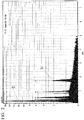
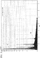
- FIG. 2 and FIG. 3 show the results of elemental analysis by energy-dispersive X-ray spectroscopy analysis (referred to below as EDS analysis) for the elements included in the cross-sectional portion shown in FIG. 1 .
- FIG. 2 is a chart of EDS analysis results at a position at a distance 0.25 ⁇ m from the surface of the insulating layer on a perpendicular line connecting the surface of the copper wire 10 and the surface of the insulating layer 20.
- FIG. 3 is a chart of EDS analysis results at a position at a distance of 1/2 (the thickness center) of the layer thickness of the entire insulating layer from the surface of the insulating layer on a perpendicular line connecting the surface of the copper wire 10 and the surface of the insulating layer 20.
- the region to be analyzed on the sample surface is a circle with a diameter of 1 ⁇ m.
- the heat-resistant particles included in the insulating layer are densely dispersed in the surface region of the insulating layer and, for example, in the shown example, since the concentration of silica fine particles included in the surface region of the insulating layer is approximately four times the concentration of silica fine particles included in the insulating layer central portion, the heat resistance of the surface region which receives the most exposure to heat at high temperatures is high. Therefore, it is possible to obtain excellent heat resistance even if the concentration of heat-resistant particles included in the insulating layer as a whole is small.
- the insulating layer is formed of an acrylic resin, a polyesterimide resin, a polyimide resin, or the like, and the heat-resistant particles included in the insulating layer are one kind or two or more kinds selected from metal oxide fine particles, metal nitride fine particles, boron nitride fine particles, silica fine particles, or the like.
- the metal oxide is one kind or a mixture of two or more kinds selected from alumina and zirconia
- the metal nitride is one kind or a mixture of two or more kinds selected from aluminum nitride and boron nitride, or the like.
- Alumina and zirconia are particularly preferable.
- the electrodeposition liquid of the present embodiment is a suspension in which resin particles and heat-resistant particles are dispersed in a solvent. It is possible to obtain this electrodeposition liquid by mixing a suspension in which resin particles are dispersed and a suspension in which heat-resistant particles are dispersed.
- the dispersion medium of the resin particle suspension may be any liquid used in the electrodeposition method and it is possible to use water or a mixture of water and an aprotic polar solvent, such as a mixture of water and N,N dimethylformamide, a mixture of water and N methylpyrrolidone, a mixture of water and dimethyl sulfoxide, or the like.
- a dispersion medium having good compatibility with the resin particle suspension is suitable, for example, one kind or a mixture of two or more kinds selected from water, methanol, methyl ethyl ketone, and the like may be used.
- the electrodeposition liquid of the present embodiment is a suspension in which resin particles and heat-resistant particles are dispersed with a turbidity of 1 mg/L or more, preferably a turbidity of 10 to 600 mg/L. It is possible to measure turbidity with a commercially available integrating spherical turbidimeter or the like. When the turbidity of the electrodeposition liquid is less than 1 mg/L, the dispersion state of the resin particles and the heat-resistant particles in the liquid is insufficient and the concentration of resin particles and heat-resistant particles is insufficient, thus, it is difficult to form an insulating layer having a sufficient thickness.
- the turbidity of the electrodeposition liquid is 1 mg/L or more, the dispersion state of the resin particles and the heat-resistant particles in the liquid is good, and a sufficient concentration of resin particles and heat-resistant particles are included, thus, it is possible to form an insulating layer having good heat resistance.
- an insulating layer is formed by passing mainly direct current between the conductive wire element immersed in the electrodeposition liquid and a counter electrode and electrically moving and electrodepositing the resin particles and the heat-resistant particles in the liquid to the wire material surface, and the electrodeposition liquid is required to have a low viscosity such that the liquid does not solidify. If the viscosity of the electrodeposition liquid is excessively high, the liquid solidifies and use for film formation is no longer possible.
- the viscosity of the electrodeposition liquid is preferably 100 cP or less, and more preferably 0.5 to 90 cP. When the viscosity of the electrodeposition liquid is 100 cP or less, it is possible to form a good insulating layer without solidification of the liquid.
- a coating material for forming an insulating layer is used.
- a high viscosity liquid is used such that the coating material does not flow down.
- the coating material which forms the coating used in the immersion method has a viscosity of 1000 cP or more. Since the resin component of the coating material which forms the coating for the immersion method is dissolved in the coating material and not a suspension in which the resin particles are dispersed in the liquid, the turbidity of the coating material is generally less than 0.01 mg/L, which is a liquid which transmits light.
- a coating material using a polyurethane resin, a polyester resin, a formal resin, a polyesterimide resin, a polyamideimide resin, or a polyimide resin is used, and the viscosity of these coating materials is 1000 cP or more and the turbidity is less than 0.01 mg/L, and the viscosity and turbidity of the liquid are totally different from those of the electrodeposition liquid for forming the insulating layer of the present invention.
- the viscosity of the electrodeposition liquid of the present embodiment is far lower than that of the coating material for insulating layer used in the immersion method.
- the kind of the resin particles included in the electrodeposition liquid of the present embodiment is one kind or a mixture of two or more kinds selected from an acrylic resin, a polyesterimide resin, a polyimide resin, or the like.
- the average particle diameter of the resin particles is preferably 1 ⁇ m or less, and more preferably 10 to 100 nm. When resin particles having an average particle diameter of 1 ⁇ m or less are used, the dispersion stability of the resin particles is improved.
- the amount of the resin particles included in the electrodeposition liquid of the present invention is preferably 1 to 30% by mass. Since the electrodeposition liquid of the present invention contains the resin particle content described above, it is possible to form an insulating layer having a sufficient thickness.
- the shape of the resin particle may be a spherical shape, an ellipsoidal shape, or another irregular shape. It is possible to determine the average particle diameter of the resin particles using a commercially available dynamic light scattering type particle diameter distribution measuring apparatus.
- the heat-resistant particles are dispersed in the electrodeposition liquid of the present embodiment along with the resin particles described above.
- the heat-resistant particles described above are one kind or two or more kinds selected from metal oxide fine particles, metal nitride fine particles, boron nitride fine particles, and silica fine particles.
- the metal oxide it is possible to use for example, one kind or a mixture of two or more kinds selected from alumina and zirconia, and, as the metal nitride, it is possible to use one kind or a mixture of two or more kinds selected from aluminum nitride and boron nitride, or the like.
- the heat-resistant particles are dispersed in advance in a dispersion medium having good compatibility with the suspension, and this dispersion liquid may be mixed with the suspension of the resin particles.
- the heat-resistant particles are preferably colloidal particles of 500 nm or less, and more preferably particles of 0.5 to 400 nm. Since the colloidal particles having the particle diameter described above are dispersed without sedimentation in the liquid, it is possible to form a heat-resistant coating uniformly including heat-resistant particles.
- the shape of the heat-resistant particles may be a spherical shape, an ellipsoidal shape, or another irregular shape. It is also possible to determine the average particle diameter of the heat-resistant particles using a commercially available dynamic light scattering type particle diameter distribution measuring apparatus.
- the amount of the heat-resistant particles is preferably 1 to 100 parts by mass with respect to 100 parts by mass of the resin particles. If the content is less than 1 part by mass, the heat resistance of the insulating layer is insufficient, and when the content exceeds 100 parts by mass, the flexibility of the insulating layer decreases. Since the electrodeposition liquid of the present invention includes the heat-resistant particle content described above, it is possible to form an insulating layer having sufficient heat resistance and flexibility. The content is more preferably 20 to 80 parts by mass with respect to 100 parts by mass of the resin particles.
- an electrodeposition film is formed by applying electricity between the conductive wire element immersed in the electrodeposition liquid and the counter electrode.
- the energization conditions at this time are the same as those in the case of using a general electrodeposition liquid.
- Baking is performed after the electrodeposition described above.
- the baking conditions may be the same as in the case of using a general electrodeposition liquid.
- the conductive wire element having the electrodeposition film formed thereon may be placed in a baking furnace, heated at 200 to 600°C for 2 to 120 seconds, and baked to form an insulating film.
- using the electrodeposition liquid of the present embodiment makes it possible to form an insulating layer in which heat-resistant particles are densely dispersed in the surface region.
- the heat-resistant particles are densely dispersed on the surface portion of the insulating layer in the heat resistant insulated wire of the present embodiment, the surface portion of the insulating layer which receives the most exposure to heat at high temperatures has high heat resistance. Therefore, it is possible to obtain excellent heat resistance even if the concentration of heat-resistant particles included in the insulating layer as a whole is small.
- the electrodeposition liquid of the present embodiment makes it possible to form an insulating layer in which heat-resistant particles are densely dispersed in the surface portion. Accordingly, it is possible to obtain an insulated coated wire having a high cut through temperature. Specifically, for example, it is possible to form a heat-resistant insulating coating where the cut through temperature increasing rate represented by the equation of [cut through temperature (°C) of insulating layer]/[cut through temperature (°C) of insulating layer] is 1.3 or more, and preferably 1.2 to 1.5.
- the electrodeposition liquid of the present embodiment is used in the electrodeposition method, it is possible to obtain a desired layer thickness by a single electrodeposition treatment. It is also possible to uniformly form an insulating coating at the corners of the flat wire. Furthermore, since it is possible to use water or a water mixture as a dispersion medium for the electrodeposition liquid, the environmental burden is small.
- Acrylic resin particles having an average particle diameter of 50 nm were dispersed in water to obtain an aqueous suspension having a resin particle concentration of 20% by mass.
- Silica particles having an average particle diameter of 10 nm or an average particle diameter of 360 nm were dispersed in water to obtain a silica sol having a silica particle concentration of 30% by mass and 70% by mass of water.
- the aqueous suspension and the silica sol described above were mixed at various ratios to prepare a plurality of kinds of aqueous dispersion type electrodeposition liquids.
- Table 1 shows the parts by mass of the silica particles with respect to 100 parts by mass of the resin particles in the electrodeposition liquid.
- Table 1 shows the turbidity, viscosity, liquid state, resin particle concentration, and average particle diameter of the resin particles of each electrodeposition liquid.
- the water content of each of the electrodeposition liquids described above was adjusted such that the resin particle concentrations were the values shown in Table 1.
- the average particle diameter of the acrylic resin particles and the silica particles was measured using a dynamic light scattering type particle diameter distribution measuring apparatus (LB 550: trade name) manufactured by Horiba.
- the turbidity of the electrodeposition liquid was measured with an integrating sphere type turbidimeter (ANA-148: trade name) manufactured by Tokyo Photoelectric Co., Ltd.
- the viscosity of the electrodeposition liquid was measured using a thin tube viscometer according to JIS (Z 8803: 2011-6).
- Each electrodeposition liquid was placed in an electrodeposition bath at 25°C and a copper wire of ⁇ 0.1 mm was passed through the electrodeposition bath at a rate of 15 m/min, energization was performed using the copper wire as an anode and the electrodeposition bath as a cathode, and acrylic resin and silica particles were electrodeposited and coated on the copper wire surface.
- a mist treatment with DMF was carried out, and the processed wire material was passed through a baking furnace and subjected to a baking treatment at a heating temperature of 300°C for a heating time of 10 seconds to form an insulating layer with a thickness of 10 ⁇ m on the copper wire surface.
- the cut through temperature was measured according to JIS (C3216-6: 2011-4).
- the cut through temperature increasing rate was obtained using the equation of [cut through temperature of insulating layer (°C)]/[cut through temperature of insulating layer resin (°C)].
- the ratio of the concentration of heat-resistant particles in the surface region of the insulating layer to the concentration of heat-resistant particles in the central portion of the insulating layer was measured in the same manner as the Si/C ratio measuring method described above.
- Zirconia particles having an average particle diameter of 100 nm were dispersed in water to obtain a zirconia sol having a zirconia particle concentration of 30% by mass and 70% by mass of water.
- alumina particles having an average particle diameter of 50 nm were dispersed in water to obtain an alumina sol having an alumina particle concentration of 30% by mass and 70% by mass of water.
- a water dispersion type electrodeposition liquid was prepared in the same manner as in Examples 1 to 13 except that these sols were used.
- Table 2 shows the parts by mass of the zirconia particles or alumina particles with respect to 100 parts by mass of the resin particles in the electrodeposition liquid.
- Table 2 shows the turbidity, viscosity, liquid state, resin particle concentration, and average particle diameter of the resin particles of the electrodeposition liquid.
- the water content of the electrodeposition liquid was adjusted such that the resin particle concentrations were the values in Table 2.
- the average particle diameter of the acrylic resin particles and the silica particles and the turbidity and viscosity of the electrodeposition liquid were measured in the same manner as in Examples 1 to 13.
- insulating layers having a thickness of 10 ⁇ m were formed in the same manner as in Examples 1 to 13.
- the flexibility, the cut through temperature, the cut through temperature increasing rate, and the ratio of the concentration of heat-resistant particles in the surface region of the insulating layer with respect to the concentration of heat-resistant particles in the central portion of the insulating layer were measured.
- the results are shown in Table 2.
- the flexibility, cut through temperature, and cut through temperature increasing rate were measured in the same manner as in Examples 1 to 13.
- the ratio of the concentration of heat-resistant particles in the surface region of the insulating layer to the concentration of heat-resistant particles in the central portion of the insulating layer was measured in the same manner as in the method for measuring the Si/C ratio, except that, in Examples 14 to 18, Zr was substituted for Si, and in Examples 19 to 23, Al was substituted for Si.
- the polyesterimide resin particles having an average particle diameter of 200 nm were dispersed in water to obtain an aqueous suspension having a resin particle concentration of 20% by mass.
- Silica particles having an average particle diameter of 10 nm were dispersed in water to obtain a silica sol having a silica particle concentration of 30% by mass and 70% by mass of water.
- the above were mixed at various ratios to prepare a plurality of aqueous dispersion type electrodeposition liquids.
- Table 3 shows the parts by mass of the silica particles with respect to 100 parts by mass of the resin particles in each electrodeposition liquid. The turbidity, viscosity, liquid state, resin particle concentration, and average particle diameter of resin particles of the electrodeposition liquid were measured. The results are shown in Table 3.
- the water content of the electrodeposition liquids was adjusted such that the resin particle concentrations were the values shown in Table 3.
- the average particle diameters of the polyesterimide resin particles and the silica particles and the turbidity and viscosity of the electrodeposition liquid described above were measured in the same manner as in Examples 1 to 13.
- insulating layers having a thickness of 10 ⁇ m were formed in the same manner as in Examples 1 to 13.
- the flexibility, the cut through temperature, the cut through temperature increasing rate, and the ratio of the concentration of heat-resistant particles in the surface region of the insulating layer with respect to the concentration of heat-resistant particles in the central portion of the insulating layer were measured.
- the results are shown in Table 3.
- the flexibility, the cut through temperature, the cut through temperature increasing rate, and the ratio of the concentration of heat-resistant particles in the surface region of the insulating layer with respect to the concentration of heat-resistant particles in the central portion of the insulating layer were measured in the same manner as in Example 1 to Example 13.
- Polyimide resin particles having an average particle diameter of 400 nm were dispersed in water to obtain an aqueous suspension having a resin particle concentration of 20% by mass.
- Silica particles having an average particle diameter of 10 nm were dispersed in water to obtain a silica sol having a silica particle concentration of 30% by mass and 70% by mass of water.
- the above were mixed to prepare an aqueous dispersion type electrodeposition liquid.
- Table 3 shows the parts by mass of the silica particles with respect to 100 parts by mass of the resin particles in the electrodeposition liquid described above.
- Table 3 shows the turbidity, viscosity, liquid state, resin particle concentration, and average particle diameter of the resin particles of the electrodeposition liquid.
- the water content of the electrodeposition liquid was adjusted such that the resin particle concentrations were the values shown in Table 3.
- the average particle diameters of the polyimide resin particles and the silica particles and the turbidity and viscosity of the electrodeposition liquid were measured in the same manner as in Examples 1 to 13.
- insulating layers having a thickness of 10 ⁇ m were formed in the same manner as in Examples 1 to 13.
- the flexibility, the cut through temperature, the cut through temperature increasing rate, and the ratio of the concentration of heat-resistant particles in the surface region of the insulating layer with respect to the concentration of heat-resistant particles in the central portion of the insulating layer were measured. The results are shown in Table 3.
- Polyamideimide resin particles having an average particle diameter of 300 nm were dispersed in water to obtain an aqueous suspension having a resin particle concentration of 20% by mass.
- Silica particles having an average particle diameter of 10 nm were dispersed in water to obtain a silica sol having a silica particle concentration of 30% by mass and 70% by mass of water.
- the above were mixed to prepare an aqueous dispersion type electrodeposition liquid.
- Table 4 shows the parts by mass of the silica particles with respect to 100 parts by mass of the resin particles in the electrodeposition liquid.
- Table 4 shows the turbidity, viscosity, liquid state, resin particle concentration, and average particle diameter of the resin particles of the electrodeposition liquid described above.
- the water content of the electrodeposition liquid was adjusted such that the resin particle concentrations were the values shown in Table 4.
- the average particle diameter of the polyimide resin particles and silica particles and the turbidity and viscosity of the electrodeposition liquid were measured in the same manner as in Examples 1 to 13.
- insulating layers having a thickness of 10 ⁇ m were formed in the same manner as in Examples 1 to 13.
- the flexibility, the cut through temperature, the cut through temperature increasing rate, and the ratio of the concentration of heat-resistant particles in the surface region of the insulating layer with respect to the concentration of heat-resistant particles in the central portion of the insulating layer were measured. The results are shown in Table 4.
- the electrodeposition liquids of Examples 1 to 40 all the electrodeposition liquids had a turbidity of 30 mg/L or more and a viscosity of 100 cP or less, the cut through temperature of the formed insulating layer was 400°C or more, the cut through temperature increasing rate was 1.2 or more, and the heat resistance was high.
- the cut through temperature and the cut through temperature increasing rate were increased according to the amount of the heat-resistant particles.
- the concentration of heat-resistant particles is preferably 1 to 100 parts by mass with respect to 100 parts by mass of the resin particles.
- Acrylic resin particles having an average particle diameter of 50 nm, polyesterimide resin particles having an average particle diameter of 200 nm, polyimide resin particles having an average particle diameter of 400 nm, and polyamideimide resin particles having an average particle diameter of 300 nm were each dispersed in water to obtain aqueous suspensions with a resin particle concentration of 20% by mass, which were used as the electrodeposition liquids.
- Table 5 shows the turbidity, viscosity, liquid state, resin particle concentration, and average particle diameter of the resin particles of the electrodeposition liquid described above. The water amount of the electrodeposition liquids was adjusted such that the resin particle concentrations were the values shown in Table 5.
- the average particle diameter of the resin particles and the turbidity and viscosity of the electrodeposition liquid were measured in the same manner as in Examples 1 to 13.
- Comparative Examples 1 to 4 the insulating layer was formed by the electrodeposition method, but since heat-resistant particles were not included, the cut through temperature did not rise and the cut through temperature increasing rate was 1 for all cases.
- Silica particles having an average particle diameter of 10 nm were dispersed in a mixed solution of xylene and butanol to obtain a silica sol.
- the silica sol described above was mixed with the coating material described above while stirring the coating material, and the silica particles were dispersed to be 20 parts by mass with respect to 100 parts by mass of the resin component of the coating material.
- the turbidity, viscosity, liquid state, and resin concentration of the electrodeposition liquid are shown in Table 5.
- the amount of xylene and butanol in the electrodeposition liquid was adjusted such that the resin particle concentration was the value shown in Table 5.
- the turbidity and viscosity of the electrodeposition liquid were measured in the same manner as in Examples 1 to 13. Using this electrodeposition liquid, the formation of an insulating layer was attempted in the same manner as in Examples 1 to 13, but since the electrodeposition liquid had a turbidity of less than 0.01 mg/L and a viscosity of more than 1000 cP, it was not possible to form the insulating layer by electrodeposition.
- Polyesterimide resin particles having an average particle diameter of 200 nm were dispersed in water to obtain an aqueous suspension having a resin particle concentration of 40% by mass.
- Silica particles having an average particle diameter of 10 nm were dispersed in water to obtain a silica sol having a silica particle concentration of 30% by mass and 70% by mass of water.
- the aqueous suspension and the silica sol were mixed such that the silica particles were 1 part by mass with respect to 100 parts by mass of the polyesterimide resin to obtain an electrodeposition liquid.
- the turbidity, viscosity, liquid state, resin particle concentration, and average particle diameter of the resin particles of the electrodeposition liquid are shown in Table 5.
- the water content of the electrodeposition liquid was adjusted such that the resin particle concentration was the value shown in Table 5.
- the average particle diameter of the resin particles and the turbidity and viscosity of the electrodeposition liquid were measured in the same manner as in Examples 1 to 13. Using these electrodeposition liquids, the formation of an insulating layer was attempted in the same manner as in Examples 1 to 13, but since the resin particle concentration was high and the viscosity of the electrodeposition liquid was excessively high, the liquid solidified and electrodeposition was not possible.
- Silica particles having an average particle diameter of 10 nm were dispersed in a mixed solution of xylene and butanol to obtain a silica sol.
- a coating material in which tris-hydroxyethyl isocyanurate modified polyesterimide was dissolved the silica sol described above was mixed with the coating material described above while stirring the coating material, and dispersion was carried out such that the silica particles were 20 parts by mass with respect to 100 parts by mass of the resin component of the coating material.
- this coating material the formation of an insulating layer using the electrodeposition method was attempted in the same manner as in Examples 1 to 13, but since the liquid was a liquid in which the resin component was dissolved, it was not possible to form an insulating layer by the electrodeposition method.
- the present invention provides a heat-resistant insulated wire with excellent heat resistance in the vicinity of the surface of an insulating layer, and an electrodeposition liquid for forming the insulating layer. Therefore, the present invention has industrial applicability.
Landscapes
- Chemical & Material Sciences (AREA)
- Spectroscopy & Molecular Physics (AREA)
- Physics & Mathematics (AREA)
- Engineering & Computer Science (AREA)
- Materials Engineering (AREA)
- Organic Chemistry (AREA)
- Life Sciences & Earth Sciences (AREA)
- Chemical Kinetics & Catalysis (AREA)
- Wood Science & Technology (AREA)
- Inorganic Chemistry (AREA)
- Health & Medical Sciences (AREA)
- Electrochemistry (AREA)
- Metallurgy (AREA)
- Nanotechnology (AREA)
- Molecular Biology (AREA)
- Ceramic Engineering (AREA)
- Organic Insulating Materials (AREA)
- Insulated Conductors (AREA)
- Paints Or Removers (AREA)
Abstract
Description
- The present invention relates to an insulated wire having a heat-resistant insulating layer and an electrodeposition liquid for forming the insulating layer.
- Priority is claimed on Japanese Patent Application No.
2014-138113, filed on July 3, 2014 - Insulated wires are widely used for magnet coils and the like. As methods for forming an insulating layer of an insulated wire, an immersion method and an electrodeposition method are known. The immersion method is a method in which a conductive wire element serving as a core material of an insulated wire is immersed in a coating material such as a resin varnish, pulled up, and dried to form an insulating coating on the surface of the wire material. The electrodeposition method is a method in which a wire material is placed in an electrodeposition liquid including a coating material component such as a resin varnish, the wire material is used as an anode or a cathode to apply an electric current between the wire material and a counter electrode, and the coating material component is electrodeposited on the wire material surface and then subjected to a baking treatment to form an insulating layer (refer to
Patent Document 1 and Patent Document 2). - The immersion method has disadvantages in that it is difficult for the coating material to attach to the corners of a flat electric wire and the layer thickness at the corners is thinner than the layer thickness at the flat portion. On the other hand, in the electrodeposition method, since the coating material is sufficiently electrodeposited even at the corners of the flat wire, there is an advantage in that it is possible to form an insulating layer in which even the corners have the same thickness as the flat portion or a greater thickness than the flat portion.
- In recent years, there has been a demand for insulated wires excellent in withstand voltage strength and heat resistance in order to handle a wide range of applications and, as a means for increasing the heat resistance of an insulating layer, a coating material for enameled wires which contains metal oxide fine particles and silica fine particles in the resin of an insulating layer is known (Patent Document 3).
- However, the coating material described in
Patent Document 3 is for the immersion method and is not able to be used for the electrodeposition method when the disclosed coating material has a liquid composition or is in a liquid state. In the immersion method, it is necessary to repeat immersion and drying several times in order to obtain a desired layer thickness, for example, repeating immersion seven times in order to form a coating having a layer thickness of 35 µm which is useful in practice. Therefore, productivity is low. Furthermore, the immersion method is not able to solve the disadvantage that the layer thickness at the corners becomes thinner than that of the flat portion in a flat wire material. In addition, the environmental burden is large since an organic solvent is used as a solvent and dispersion medium of the resin and oxide fine particles. - Furthermore, in the immersion method, in a case where silica fine particles are contained in the insulating layer, since the immersion in a coating material including silica fine particles is repeated, silica fine particles are included in each layer such that the silica fine particles are in a dispersed state throughout the entire insulating layer. However, since it is the surface of the insulating layer which receives the most exposure to heat at high temperatures, the insulating layer surface is easily damaged if the concentration of silica fine particles in the vicinity of the surface of the insulating layer is small.
-
- [Patent Document 1] Japanese Unexamined Patent Application, First Publication No.
S62-037396 - [Patent Document 2] Japanese Unexamined Patent Application, First Publication No.
H03-241609 - [Patent Document 3] Japanese Unexamined Patent Application, First Publication No.
2001-307557 - The present invention solves the problems described above in insulated wires formed by an immersion method in the related art and methods for manufacturing the same and provides a heat-resistant insulated wire excellent in heat resistance in the vicinity of the surface of the insulating layer and an electrodeposition liquid for forming the insulating layer.
- Each aspect of the present invention has the following configuration.
- [1] A heat-resistant insulated wire including a heat-resistant insulating layer, in which heat-resistant particles are contained in the insulating layer, and the heat-resistant particles are densely dispersed in a surface region of the insulating layer. The heat-resistant insulating layer described above is usually formed on the surface of the conductive wire element. The term "densely dispersed" means that the heat-resistant particles are dispersed in the surface region of the insulating layer at a relatively higher density than in the other portions of the insulating layer.
- [2] The heat-resistant insulated wire according to [1], in which the heat-resistant particles are densely dispersed in a region having a thickness of 0.5 µm from the surface of the insulating layer.
- [3] The heat-resistant insulated wire according to [1] or [2], in which a concentration (quantity) of the heat-resistant particles included in the region having a thickness of 0.5 µm from the surface of the insulating layer is two times or more a concentration (quantity) of the heat-resistant particles included in a central portion of the insulating layer in a thickness direction. More preferably, the density of the heat-resistant particles included in the 0.5 µm region is 2 to 6 times the density of the heat-resistant particles included in the central portion in the thickness direction of the insulating layer.
- [4] An electrodeposition liquid for forming an insulating layer, used for forming the insulating layer of the insulated wire according to [1], in which the heat-resistant particles are dispersed in a suspension in which resin particles are dispersed, with a viscosity of 100 cP or less and a turbidity of 1 mg/L or more. More preferably, the viscosity of the electrodeposition liquid is 0.5 to 50 cP and the turbidity is 10 to 600 mg/L.
- [5] The electrodeposition liquid for forming an insulating layer according to [4], in which the amount of the resin particles is 1 to 30% by mass and the amount of the heat-resistant particles is 1 to 100 parts by mass with respect to 100 parts by mass of the resin particles.
- [6] The electrodeposition liquid for forming an insulating layer according to [4] or [5], in which an average particle diameter of the resin particles is 1 µm or less and an average particle diameter of the heat-resistant particles is 500 nm or less. The average particle diameter of the resin particles is more preferably 10 to 100 nm, and the average particle diameter of the heat-resistant particles is more preferably 0.5 to 400 nm.
- [7] The electrodeposition liquid for forming an insulating layer according to any one of [4] to [6], which forms an insulating layer in which a cut through temperature increasing rate of the insulating layer is 1.2 or more. The cut through temperature increasing rate of the insulating layer is more preferably 1.2 to 1.6.
- [8] The electrodeposition liquid for forming an insulating layer according to any one of [5] to [7], in which the resin particles are one kind or two or more kinds selected from an acrylic resin, a polyesterimide resin, a polyimide resin, or a polyamideimide resin.
- [9] The electrodeposition liquid for forming an insulating layer according to any one of [5] to [8], in which the heat-resistant particles are one kind or two or more kinds selected from metal oxide fine particles, metal nitride fine particles, boron nitride fine particles, and silica fine particles. As the metal oxide, it is possible to use one kind or a mixture of two or more kinds selected from alumina, zirconia, and the like, and, as the metal nitride, it is possible to use one kind or a mixture of two or more kinds selected from aluminum nitride, boron nitride, and the like.
- In a heat-resistant insulated wire according to one aspect of the present invention, since heat-resistant particles are densely dispersed on the surface portion of the insulating layer, the surface portion of the insulating layer which receives the most exposure to heat at high temperature has high heat resistance. Therefore, it is possible to obtain excellent heat resistance even if the total concentration of heat-resistant particles included in the insulating layer as a whole is small.
- In the electrodeposition liquid according to another aspect of the present invention, it is possible to form an insulating layer in which heat-resistant particles are densely dispersed in the surface portion. Accordingly, it is possible to obtain an insulated coated wire having a high cut through temperature. For example, it is possible to form a heat-resistant insulating coating where the cut through temperature increasing rate represented by the equation of [cut through temperature (°C) of insulating layer]/[cut through temperature (°C) of insulating layer resin] is 1.2 or more, preferably 1.2 to 1.6, and more preferably 1.3 to 1.5.
- Since the electrodeposition liquid described above is used in the electrodeposition method, it is possible to obtain a desired layer thickness by a single electrodeposition treatment. In addition, it is possible to uniformly form an insulating coating on the corners of a flat wire. Furthermore, since it is possible to use water as a dispersion medium for the electrodeposition liquid, the environmental burden is small.
-
-
FIG. 1 is a partial cross-sectional photograph of an insulated wire formed in Example 1. -
FIG. 2 is an EDS analysis chart at a position at a distance of 0.25 µm from the insulating layer surface on a perpendicular line connecting the surface of acopper wire 10 and the surface of aninsulating layer 20 inFIG. 1 . -
FIG. 3 is an EDS analysis chart at a position at a distance from the surface of the insulating layer which is 1/2 of the layer thickness of the entire insulating layer on the perpendicular line connecting the surface of thecopper wire 10 and the surface of theinsulating layer 20 inFIG. 1 . - A heat-resistant insulated wire according to one embodiment of the present invention is an insulated wire having a conductive wire element and a heat-resistant insulating layer provided on the surface of the conductive wire element, in which heat-resistant particles are contained in the insulating layer and the heat-resistant particles are densely dispersed in a surface region of the insulating layer. The conductive wire element may be any commonly used metal such as copper, copper alloy, silver, silver alloy, aluminum, and aluminum alloy. In addition, the shape thereof may be any shape having a circular cross-section, an elliptical cross-section, a quadrangular cross-section, a flat plate cross-section, or the like. The insulating layer is formed with a substantially uniform thickness on the surface of the conductive wire element in a case where the conductive wire element has a circular cross-section or an elliptical cross-section. On the other hand, in a case where the conductive wire element has a cross-sectional shape with corners, the insulating layer is formed to be relatively thicker (for example, approximately 10 to 30% thicker) at the corners than at the other portions.
- The surface region of the insulating layer is a region from the surface of the insulating layer to a distance (depth) of up to 0.5 µm, on a perpendicular line connecting the surface of the conductive wire element of the insulated wire and the insulating layer surface. In general, the layer thickness of the entire insulating layer is approximately 2 to 50 µm, and usually 3 to 30 µm.
- In the heat-resistant insulated wire according to the present embodiment, preferably, the concentration (quantity) of the heat-resistant particles included in the region of 0.5 µm from the surface of the insulating layer is two times or more the concentration (quantity) of the heat-resistant particles included in the central portion in the thickness direction of the insulating layer. With respect to the layer thickness L of the entire insulating layer on the perpendicular line connecting the surface of the conductive wire element and the surface of the insulating layer, the central portion in the thickness direction of the insulating layer is a range from a position of 1/3 L to a position of 2/3 L from the surface of the insulating layer.
- An example of the heat-resistant insulated wire of the present embodiment is shown in
FIG. 1. FIG. 1 is a partial cross-sectional view of a heat-resistant insulated wire according to the present embodiment. This heat-resistant insulated wire has a conductive wire element 10 (copper wire 10 in the shown example) and an insulatinglayer 20 formed of a heat-resistant resin covering thecopper wire 10 with a certain thickness, and heat-resistant particles 30 are included in the insulatinglayer 20. In the diagram, the white spots inside the insulatinglayer 20 are the heat-resistant particles 30. The heat-resistant particles 30 in the example shown are silica fine particles. As shown in the diagram, white spots are densely dispersed in the region of 0.5 µm from the surface of the insulatinglayer 20, and it is understood that the heat-resistant particles 30 are unevenly distributed in this portion. -
FIG. 2 andFIG. 3 show the results of elemental analysis by energy-dispersive X-ray spectroscopy analysis (referred to below as EDS analysis) for the elements included in the cross-sectional portion shown inFIG. 1 .FIG. 2 is a chart of EDS analysis results at a position at a distance 0.25 µm from the surface of the insulating layer on a perpendicular line connecting the surface of thecopper wire 10 and the surface of the insulatinglayer 20.FIG. 3 is a chart of EDS analysis results at a position at a distance of 1/2 (the thickness center) of the layer thickness of the entire insulating layer from the surface of the insulating layer on a perpendicular line connecting the surface of thecopper wire 10 and the surface of the insulatinglayer 20. The region to be analyzed on the sample surface is a circle with a diameter of 1 µm. - The ratio (Si/C) of the silicon intensity peak (Si in the diagram) to the carbon intensity peak (C in the diagram) is the average value obtained after performing analysis five times and Si/C=20/80 in
FIG. 2 , but Si/C=5/95 inFIG. 3 , and the concentration of silica fine particles included in the surface region of the insulating layer shown inFIG. 2 is approximately four times the concentration of silica fine particles included in the central portion of the insulating layer shown inFIG. 3 . - In the heat-resistant insulated wire according to the present embodiment, the heat-resistant particles included in the insulating layer are densely dispersed in the surface region of the insulating layer and, for example, in the shown example, since the concentration of silica fine particles included in the surface region of the insulating layer is approximately four times the concentration of silica fine particles included in the insulating layer central portion, the heat resistance of the surface region which receives the most exposure to heat at high temperatures is high. Therefore, it is possible to obtain excellent heat resistance even if the concentration of heat-resistant particles included in the insulating layer as a whole is small.
- The insulating layer is formed of an acrylic resin, a polyesterimide resin, a polyimide resin, or the like, and the heat-resistant particles included in the insulating layer are one kind or two or more kinds selected from metal oxide fine particles, metal nitride fine particles, boron nitride fine particles, silica fine particles, or the like. The metal oxide is one kind or a mixture of two or more kinds selected from alumina and zirconia, and the metal nitride is one kind or a mixture of two or more kinds selected from aluminum nitride and boron nitride, or the like. Alumina and zirconia are particularly preferable.
- It is possible to form the insulating layer using the following electrodeposition liquid. The electrodeposition liquid of the present embodiment is a suspension in which resin particles and heat-resistant particles are dispersed in a solvent. It is possible to obtain this electrodeposition liquid by mixing a suspension in which resin particles are dispersed and a suspension in which heat-resistant particles are dispersed. The dispersion medium of the resin particle suspension may be any liquid used in the electrodeposition method and it is possible to use water or a mixture of water and an aprotic polar solvent, such as a mixture of water and N,N dimethylformamide, a mixture of water and N methylpyrrolidone, a mixture of water and dimethyl sulfoxide, or the like. For the dispersion medium of the heat-resistant particle suspension, a dispersion medium having good compatibility with the resin particle suspension is suitable, for example, one kind or a mixture of two or more kinds selected from water, methanol, methyl ethyl ketone, and the like may be used.
- The electrodeposition liquid of the present embodiment is a suspension in which resin particles and heat-resistant particles are dispersed with a turbidity of 1 mg/L or more, preferably a turbidity of 10 to 600 mg/L. It is possible to measure turbidity with a commercially available integrating spherical turbidimeter or the like. When the turbidity of the electrodeposition liquid is less than 1 mg/L, the dispersion state of the resin particles and the heat-resistant particles in the liquid is insufficient and the concentration of resin particles and heat-resistant particles is insufficient, thus, it is difficult to form an insulating layer having a sufficient thickness. If the turbidity of the electrodeposition liquid is 1 mg/L or more, the dispersion state of the resin particles and the heat-resistant particles in the liquid is good, and a sufficient concentration of resin particles and heat-resistant particles are included, thus, it is possible to form an insulating layer having good heat resistance.
- In the electrodeposition method, an insulating layer is formed by passing mainly direct current between the conductive wire element immersed in the electrodeposition liquid and a counter electrode and electrically moving and electrodepositing the resin particles and the heat-resistant particles in the liquid to the wire material surface, and the electrodeposition liquid is required to have a low viscosity such that the liquid does not solidify. If the viscosity of the electrodeposition liquid is excessively high, the liquid solidifies and use for film formation is no longer possible. The viscosity of the electrodeposition liquid is preferably 100 cP or less, and more preferably 0.5 to 90 cP. When the viscosity of the electrodeposition liquid is 100 cP or less, it is possible to form a good insulating layer without solidification of the liquid.
- On the other hand, in the immersion method, a coating material for forming an insulating layer is used. When this coating material is applied to the surface of the conductive wire element of the insulated wire, a high viscosity liquid is used such that the coating material does not flow down. In general, the coating material which forms the coating used in the immersion method has a viscosity of 1000 cP or more. Since the resin component of the coating material which forms the coating for the immersion method is dissolved in the coating material and not a suspension in which the resin particles are dispersed in the liquid, the turbidity of the coating material is generally less than 0.01 mg/L, which is a liquid which transmits light.
- In addition, in the immersion method, specifically, a coating material using a polyurethane resin, a polyester resin, a formal resin, a polyesterimide resin, a polyamideimide resin, or a polyimide resin is used, and the viscosity of these coating materials is 1000 cP or more and the turbidity is less than 0.01 mg/L, and the viscosity and turbidity of the liquid are totally different from those of the electrodeposition liquid for forming the insulating layer of the present invention. The viscosity of the electrodeposition liquid of the present embodiment is far lower than that of the coating material for insulating layer used in the immersion method.
- The kind of the resin particles included in the electrodeposition liquid of the present embodiment is one kind or a mixture of two or more kinds selected from an acrylic resin, a polyesterimide resin, a polyimide resin, or the like. The average particle diameter of the resin particles is preferably 1 µm or less, and more preferably 10 to 100 nm. When resin particles having an average particle diameter of 1 µm or less are used, the dispersion stability of the resin particles is improved. The amount of the resin particles included in the electrodeposition liquid of the present invention is preferably 1 to 30% by mass. Since the electrodeposition liquid of the present invention contains the resin particle content described above, it is possible to form an insulating layer having a sufficient thickness. The shape of the resin particle may be a spherical shape, an ellipsoidal shape, or another irregular shape. It is possible to determine the average particle diameter of the resin particles using a commercially available dynamic light scattering type particle diameter distribution measuring apparatus.
- The heat-resistant particles are dispersed in the electrodeposition liquid of the present embodiment along with the resin particles described above. The heat-resistant particles described above are one kind or two or more kinds selected from metal oxide fine particles, metal nitride fine particles, boron nitride fine particles, and silica fine particles. As the metal oxide, it is possible to use for example, one kind or a mixture of two or more kinds selected from alumina and zirconia, and, as the metal nitride, it is possible to use one kind or a mixture of two or more kinds selected from aluminum nitride and boron nitride, or the like. In order to uniformly disperse the heat-resistant particles in the suspension of the resin particles, the heat-resistant particles are dispersed in advance in a dispersion medium having good compatibility with the suspension, and this dispersion liquid may be mixed with the suspension of the resin particles.
- The heat-resistant particles are preferably colloidal particles of 500 nm or less, and more preferably particles of 0.5 to 400 nm. Since the colloidal particles having the particle diameter described above are dispersed without sedimentation in the liquid, it is possible to form a heat-resistant coating uniformly including heat-resistant particles. The shape of the heat-resistant particles may be a spherical shape, an ellipsoidal shape, or another irregular shape. It is also possible to determine the average particle diameter of the heat-resistant particles using a commercially available dynamic light scattering type particle diameter distribution measuring apparatus.
- The amount of the heat-resistant particles is preferably 1 to 100 parts by mass with respect to 100 parts by mass of the resin particles. If the content is less than 1 part by mass, the heat resistance of the insulating layer is insufficient, and when the content exceeds 100 parts by mass, the flexibility of the insulating layer decreases. Since the electrodeposition liquid of the present invention includes the heat-resistant particle content described above, it is possible to form an insulating layer having sufficient heat resistance and flexibility. The content is more preferably 20 to 80 parts by mass with respect to 100 parts by mass of the resin particles.
- Using the electrodeposition liquid of the present embodiment, an electrodeposition film is formed by applying electricity between the conductive wire element immersed in the electrodeposition liquid and the counter electrode. The energization conditions at this time are the same as those in the case of using a general electrodeposition liquid. For example, it is possible to perform electrodeposition with a DC voltage of 5 to 100 V, an electrodeposition time of 0.1 to 30 seconds, and an electrodeposition liquid temperature of 5 to 40°C. Since the charged states of the heat-resistant particles and the resin particles are different and the resin particles are more easily electrodeposited than the heat-resistant particles, the concentration of the heat-resistant particles is higher on the surface of the electrodeposition film.
- Baking is performed after the electrodeposition described above. The baking conditions may be the same as in the case of using a general electrodeposition liquid. For example, the conductive wire element having the electrodeposition film formed thereon may be placed in a baking furnace, heated at 200 to 600°C for 2 to 120 seconds, and baked to form an insulating film.
- As described above, using the electrodeposition liquid of the present embodiment makes it possible to form an insulating layer in which heat-resistant particles are densely dispersed in the surface region.
- Since the heat-resistant particles are densely dispersed on the surface portion of the insulating layer in the heat resistant insulated wire of the present embodiment, the surface portion of the insulating layer which receives the most exposure to heat at high temperatures has high heat resistance. Therefore, it is possible to obtain excellent heat resistance even if the concentration of heat-resistant particles included in the insulating layer as a whole is small.
- The electrodeposition liquid of the present embodiment makes it possible to form an insulating layer in which heat-resistant particles are densely dispersed in the surface portion. Accordingly, it is possible to obtain an insulated coated wire having a high cut through temperature. Specifically, for example, it is possible to form a heat-resistant insulating coating where the cut through temperature increasing rate represented by the equation of [cut through temperature (°C) of insulating layer]/[cut through temperature (°C) of insulating layer] is 1.3 or more, and preferably 1.2 to 1.5.
- Since the electrodeposition liquid of the present embodiment is used in the electrodeposition method, it is possible to obtain a desired layer thickness by a single electrodeposition treatment. It is also possible to uniformly form an insulating coating at the corners of the flat wire. Furthermore, since it is possible to use water or a water mixture as a dispersion medium for the electrodeposition liquid, the environmental burden is small.
- Examples of the present invention are shown below together with Comparative Examples.
- Acrylic resin particles having an average particle diameter of 50 nm were dispersed in water to obtain an aqueous suspension having a resin particle concentration of 20% by mass. Silica particles having an average particle diameter of 10 nm or an average particle diameter of 360 nm were dispersed in water to obtain a silica sol having a silica particle concentration of 30% by mass and 70% by mass of water. Furthermore, the aqueous suspension and the silica sol described above were mixed at various ratios to prepare a plurality of kinds of aqueous dispersion type electrodeposition liquids. Table 1 shows the parts by mass of the silica particles with respect to 100 parts by mass of the resin particles in the electrodeposition liquid. Table 1 shows the turbidity, viscosity, liquid state, resin particle concentration, and average particle diameter of the resin particles of each electrodeposition liquid.
- The water content of each of the electrodeposition liquids described above was adjusted such that the resin particle concentrations were the values shown in Table 1. The average particle diameter of the acrylic resin particles and the silica particles was measured using a dynamic light scattering type particle diameter distribution measuring apparatus (LB 550: trade name) manufactured by Horiba. The turbidity of the electrodeposition liquid was measured with an integrating sphere type turbidimeter (ANA-148: trade name) manufactured by Tokyo Photoelectric Co., Ltd. The viscosity of the electrodeposition liquid was measured using a thin tube viscometer according to JIS (Z 8803: 2011-6).
- Each electrodeposition liquid was placed in an electrodeposition bath at 25°C and a copper wire of φ 0.1 mm was passed through the electrodeposition bath at a rate of 15 m/min, energization was performed using the copper wire as an anode and the electrodeposition bath as a cathode, and acrylic resin and silica particles were electrodeposited and coated on the copper wire surface. After electrodeposition, a mist treatment with DMF was carried out, and the processed wire material was passed through a baking furnace and subjected to a baking treatment at a heating temperature of 300°C for a heating time of 10 seconds to form an insulating layer with a thickness of 10 µm on the copper wire surface.
- For these insulated wires, the flexibility, the cut through temperature, the cut through temperature increasing rate, and the ratio of the concentration of heat-resistant particles in the surface region of the insulating layer with respect to the concentration of heat-resistant particles in the central portion of the insulating layer were measured. The results are shown in Table 1.
- After being wound around itself according to JIS (C 3005: 2000-4.20.1), the presence or absence of peeling of the insulating layer was checked with an optical microscope, the absence of peeling was indicated by "O", and presence of peeling was indicated by "X". The cut through temperature was measured according to JIS (C3216-6: 2011-4). The cut through temperature increasing rate was obtained using the equation of [cut through temperature of insulating layer (°C)]/[cut through temperature of insulating layer resin (°C)]. The ratio of the concentration of heat-resistant particles in the surface region of the insulating layer to the concentration of heat-resistant particles in the central portion of the insulating layer was measured in the same manner as the Si/C ratio measuring method described above.
- Zirconia particles having an average particle diameter of 100 nm were dispersed in water to obtain a zirconia sol having a zirconia particle concentration of 30% by mass and 70% by mass of water. In addition, alumina particles having an average particle diameter of 50 nm were dispersed in water to obtain an alumina sol having an alumina particle concentration of 30% by mass and 70% by mass of water. A water dispersion type electrodeposition liquid was prepared in the same manner as in Examples 1 to 13 except that these sols were used. Table 2 shows the parts by mass of the zirconia particles or alumina particles with respect to 100 parts by mass of the resin particles in the electrodeposition liquid. Table 2 shows the turbidity, viscosity, liquid state, resin particle concentration, and average particle diameter of the resin particles of the electrodeposition liquid. The water content of the electrodeposition liquid was adjusted such that the resin particle concentrations were the values in Table 2. The average particle diameter of the acrylic resin particles and the silica particles and the turbidity and viscosity of the electrodeposition liquid were measured in the same manner as in Examples 1 to 13.
- Using these electrodeposition liquids, insulating layers having a thickness of 10 µm were formed in the same manner as in Examples 1 to 13. For this insulated wire, the flexibility, the cut through temperature, the cut through temperature increasing rate, and the ratio of the concentration of heat-resistant particles in the surface region of the insulating layer with respect to the concentration of heat-resistant particles in the central portion of the insulating layer were measured. The results are shown in Table 2. The flexibility, cut through temperature, and cut through temperature increasing rate were measured in the same manner as in Examples 1 to 13. The ratio of the concentration of heat-resistant particles in the surface region of the insulating layer to the concentration of heat-resistant particles in the central portion of the insulating layer was measured in the same manner as in the method for measuring the Si/C ratio, except that, in Examples 14 to 18, Zr was substituted for Si, and in Examples 19 to 23, Al was substituted for Si.
- The polyesterimide resin particles having an average particle diameter of 200 nm were dispersed in water to obtain an aqueous suspension having a resin particle concentration of 20% by mass. Silica particles having an average particle diameter of 10 nm were dispersed in water to obtain a silica sol having a silica particle concentration of 30% by mass and 70% by mass of water. Furthermore, the above were mixed at various ratios to prepare a plurality of aqueous dispersion type electrodeposition liquids. Table 3 shows the parts by mass of the silica particles with respect to 100 parts by mass of the resin particles in each electrodeposition liquid. The turbidity, viscosity, liquid state, resin particle concentration, and average particle diameter of resin particles of the electrodeposition liquid were measured. The results are shown in Table 3. The water content of the electrodeposition liquids was adjusted such that the resin particle concentrations were the values shown in Table 3. The average particle diameters of the polyesterimide resin particles and the silica particles and the turbidity and viscosity of the electrodeposition liquid described above were measured in the same manner as in Examples 1 to 13.
- Using these electrodeposition liquids, insulating layers having a thickness of 10 µm were formed in the same manner as in Examples 1 to 13. For these insulated wires, the flexibility, the cut through temperature, the cut through temperature increasing rate, and the ratio of the concentration of heat-resistant particles in the surface region of the insulating layer with respect to the concentration of heat-resistant particles in the central portion of the insulating layer were measured. The results are shown in Table 3. The flexibility, the cut through temperature, the cut through temperature increasing rate, and the ratio of the concentration of heat-resistant particles in the surface region of the insulating layer with respect to the concentration of heat-resistant particles in the central portion of the insulating layer were measured in the same manner as in Example 1 to Example 13.
- Polyimide resin particles having an average particle diameter of 400 nm were dispersed in water to obtain an aqueous suspension having a resin particle concentration of 20% by mass. Silica particles having an average particle diameter of 10 nm were dispersed in water to obtain a silica sol having a silica particle concentration of 30% by mass and 70% by mass of water. Furthermore, the above were mixed to prepare an aqueous dispersion type electrodeposition liquid. Table 3 shows the parts by mass of the silica particles with respect to 100 parts by mass of the resin particles in the electrodeposition liquid described above. Table 3 shows the turbidity, viscosity, liquid state, resin particle concentration, and average particle diameter of the resin particles of the electrodeposition liquid. The water content of the electrodeposition liquid was adjusted such that the resin particle concentrations were the values shown in Table 3. The average particle diameters of the polyimide resin particles and the silica particles and the turbidity and viscosity of the electrodeposition liquid were measured in the same manner as in Examples 1 to 13.
- Using these electrodeposition liquids, insulating layers having a thickness of 10 µm were formed in the same manner as in Examples 1 to 13. For these insulated wires, the flexibility, the cut through temperature, the cut through temperature increasing rate, and the ratio of the concentration of heat-resistant particles in the surface region of the insulating layer with respect to the concentration of heat-resistant particles in the central portion of the insulating layer were measured. The results are shown in Table 3.
- The flexibility, the cut through temperature, the cut through temperature increasing rate, and the ratio of the concentration of heat-resistant particles in the surface region of the insulating layer with respect to the concentration of heat-resistant particles in the central portion of the insulating layer were measured in the same manner as in Example 1 to Example 13.
- Polyamideimide resin particles having an average particle diameter of 300 nm were dispersed in water to obtain an aqueous suspension having a resin particle concentration of 20% by mass. Silica particles having an average particle diameter of 10 nm were dispersed in water to obtain a silica sol having a silica particle concentration of 30% by mass and 70% by mass of water. Furthermore, the above were mixed to prepare an aqueous dispersion type electrodeposition liquid. Table 4 shows the parts by mass of the silica particles with respect to 100 parts by mass of the resin particles in the electrodeposition liquid. Table 4 shows the turbidity, viscosity, liquid state, resin particle concentration, and average particle diameter of the resin particles of the electrodeposition liquid described above. The water content of the electrodeposition liquid was adjusted such that the resin particle concentrations were the values shown in Table 4. The average particle diameter of the polyimide resin particles and silica particles and the turbidity and viscosity of the electrodeposition liquid were measured in the same manner as in Examples 1 to 13.
- Using these electrodeposition liquids, insulating layers having a thickness of 10 µm were formed in the same manner as in Examples 1 to 13. For these insulated wires, the flexibility, the cut through temperature, the cut through temperature increasing rate, and the ratio of the concentration of heat-resistant particles in the surface region of the insulating layer with respect to the concentration of heat-resistant particles in the central portion of the insulating layer were measured. The results are shown in Table 4.
- The flexibility, the cut through temperature, the cut through temperature increasing rate, and the ratio of the concentration of heat-resistant particles in the surface region of the insulating layer with respect to the concentration of heat-resistant particles in the central portion of the insulating layer were measured in the same manner as in Example 1 to Example 13.
- In the electrodeposition liquids of Examples 1 to 40, all the electrodeposition liquids had a turbidity of 30 mg/L or more and a viscosity of 100 cP or less, the cut through temperature of the formed insulating layer was 400°C or more, the cut through temperature increasing rate was 1.2 or more, and the heat resistance was high. In addition, in all of the resin types, the cut through temperature and the cut through temperature increasing rate were increased according to the amount of the heat-resistant particles. In Example 8, since the amount of silica particles was large, peeling of the insulating layer occurred in the flexibility test. From this result, it was found that the concentration of heat-resistant particles is preferably 1 to 100 parts by mass with respect to 100 parts by mass of the resin particles.
- Acrylic resin particles having an average particle diameter of 50 nm, polyesterimide resin particles having an average particle diameter of 200 nm, polyimide resin particles having an average particle diameter of 400 nm, and polyamideimide resin particles having an average particle diameter of 300 nm were each dispersed in water to obtain aqueous suspensions with a resin particle concentration of 20% by mass, which were used as the electrodeposition liquids. Table 5 shows the turbidity, viscosity, liquid state, resin particle concentration, and average particle diameter of the resin particles of the electrodeposition liquid described above. The water amount of the electrodeposition liquids was adjusted such that the resin particle concentrations were the values shown in Table 5. The average particle diameter of the resin particles and the turbidity and viscosity of the electrodeposition liquid were measured in the same manner as in Examples 1 to 13.
- Using these electrodeposition liquids, insulating layers having a thickness of 10 µm were formed in the same manner as in Examples 1 to 13. For these insulated wires, the flexibility, the cut through temperature, and the cut through temperature increasing rate were measured. The results are shown in Table 5. The flexibility, the cut through temperature, and cut through temperature increasing rate were measured in the same manner as in Examples 1 to 13.
- In Comparative Examples 1 to 4, the insulating layer was formed by the electrodeposition method, but since heat-resistant particles were not included, the cut through temperature did not rise and the cut through temperature increasing rate was 1 for all cases.
- Silica particles having an average particle diameter of 10 nm were dispersed in a mixed solution of xylene and butanol to obtain a silica sol. Using a coating material in which a polyesterimide resin was dissolved, the silica sol described above was mixed with the coating material described above while stirring the coating material, and the silica particles were dispersed to be 20 parts by mass with respect to 100 parts by mass of the resin component of the coating material.
- The turbidity, viscosity, liquid state, and resin concentration of the electrodeposition liquid are shown in Table 5. The amount of xylene and butanol in the electrodeposition liquid was adjusted such that the resin particle concentration was the value shown in Table 5. The turbidity and viscosity of the electrodeposition liquid were measured in the same manner as in Examples 1 to 13. Using this electrodeposition liquid, the formation of an insulating layer was attempted in the same manner as in Examples 1 to 13, but since the electrodeposition liquid had a turbidity of less than 0.01 mg/L and a viscosity of more than 1000 cP, it was not possible to form the insulating layer by electrodeposition.
- Polyesterimide resin particles having an average particle diameter of 200 nm were dispersed in water to obtain an aqueous suspension having a resin particle concentration of 40% by mass. Silica particles having an average particle diameter of 10 nm were dispersed in water to obtain a silica sol having a silica particle concentration of 30% by mass and 70% by mass of water. The aqueous suspension and the silica sol were mixed such that the silica particles were 1 part by mass with respect to 100 parts by mass of the polyesterimide resin to obtain an electrodeposition liquid. The turbidity, viscosity, liquid state, resin particle concentration, and average particle diameter of the resin particles of the electrodeposition liquid are shown in Table 5. The water content of the electrodeposition liquid was adjusted such that the resin particle concentration was the value shown in Table 5. The average particle diameter of the resin particles and the turbidity and viscosity of the electrodeposition liquid were measured in the same manner as in Examples 1 to 13. Using these electrodeposition liquids, the formation of an insulating layer was attempted in the same manner as in Examples 1 to 13, but since the resin particle concentration was high and the viscosity of the electrodeposition liquid was excessively high, the liquid solidified and electrodeposition was not possible.
- Silica particles having an average particle diameter of 10 nm were dispersed in a mixed solution of xylene and butanol to obtain a silica sol. Using a coating material in which tris-hydroxyethyl isocyanurate modified polyesterimide was dissolved, the silica sol described above was mixed with the coating material described above while stirring the coating material, and dispersion was carried out such that the silica particles were 20 parts by mass with respect to 100 parts by mass of the resin component of the coating material. Using this coating material, the formation of an insulating layer using the electrodeposition method was attempted in the same manner as in Examples 1 to 13, but since the liquid was a liquid in which the resin component was dissolved, it was not possible to form an insulating layer by the electrodeposition method.
[Table 1] Example No. 1 2 3 4 5 6 7 8 9 10 11 12 13 Resin Acrylic resin 100 100 100 100 100 100 100 100 100 100 100 100 100 Polyesterimide resin - - - - - - - - - - - - - Polyimide resin - - - - - - - - - - - - - Polyamideimide resin - - - - - - - - - - - - - Heat-resistant parti cles Silica sol (average particle diameter 10 nm) 100 80 50 20 1 1 1 110 - - - - - Electrodeposition liquid Silica sol (average particle diameter 360 nm) - - - - - - - - 100 80 50 20 1 Zirconia sol (average particle diameter 100 nm) - - - - - - - - - - - - - Alumina sol (average particle diameter 50 nm) - - - - - - - - - - - - - Turbidity (mg/L) 30 30 30 30 30 50 70 30 550 543 252 35 30 Viscosity (cP) 1 1 1 1 1 70 90 1 1 1 1 1 1 Liquid state Aqueous dispersion Aqueous dispersion Aqueous dispersion Aqueous dispersion Aqueous dispersion Aqueous dispersion Aqueous dispersion Aqueous dispersion Aqueous dispersion Aqueous dispersion Aqueous dispersion Aqueous dispersion Aqueous dispersion Resin concentration (mass%) 5 5 5 5 5 10 20 5 5 5 5 5 5 Average particle diameter of resin particles (nm) 50 50 50 50 50 50 50 50 50 50 50 50 50 Flexibility (not peeled ○, peeled ×) ○ ○ ○ ○ ○ ○ ○ × ○ ○ ○ ○ ○ Insulating coating Cut through temperature (°C) 450 445 420 412 400 402 400 450 457 440 420 412 400 Cut through temperature increasing rate 1.50 1.48 1.40 1.37 1.33 1.34 1.33 1.50 1.52 1.47 1.40 1.37 1.33 (Concentration of heat resistant-particles in surface)/(Concentration of heat resistant-particles in central portion) 5.2 4.1 4.0 3.5 2.5 2.8 2.7 4.3 5.8 4.2 4.0 3.5 2.6 [Table 2] Example No. 14 15 16 17 18 19 20 21 22 23 Electrodeposition liquid Acrylic resin 100 100 100 100 100 100 100 100 100 100 Resin Polyesterimide resin - - - - - - - - - - Polyimide resin - - - - - - - - - - Polyamideimide resin - - - - - - - - - - Silica sol (average particle diameter 10 nm) - - - - - - - - - - Heat-resistant particles Silica sol (average particle diameter 360 nm) - - - - - - - - - - Zirconia sol (average particle diameter 100 nm) 100 80 50 20 1 - - - - - Alumina sol (average particle diameter 50 nm) - - - - - 100 80 50 20 1 Turbidity (mg/L) 320 315 150 35 30 50 47 40 33 30 Viscosity (cP) 1 1 1 1 1 1 1 1 1 1 Liquid state Aqueous dispersion Aqueous dispersion Aqueous dispersion Aqueous dispersion Aqueous dispersion Aqueous dispersion Aqueous dispersion Aqueous dispersion Aqueous dispersion Aqueous dispersion Resin concentration (mass%) 5 5 5 5 5 5 5 5 5 5 Average particle diameter of resin particles (nm) 50 50 50 50 50 50 50 50 50 50 Insulating coating Flexibility (not peeled ○, peeled ×) ○ ○ ○ ○ ○ ○ ○ ○ ○ ○ Cut through temperature (°C) 451 441 422 415 400 450 442 420 413 400 Cut through temperature increasing rate 1.50 1.47 1.40 1.38 1.33 1.50 1.47 1.40 1.37 1.33 (Concentration of heat resistant-particles in surface)/(Concentration of heat resistant-particles in central portion) 5.0 4.2 4.0 3.6 2.1 5.0 4.1 3.6 3.6 2.3 [Table 3] Example No. 24 25 26 27 28 29 30 31 32 33 34 35 Electrodeposition liquid Resin Acrylic resin - - - - - - - - - - - - Polyesterimide resin 100 100 100 100 100 100 100 - - - - - Polyimide resin - - - - - - - 100 100 100 100 100 Polyamideimide resin - - - - - - - - - - - - Heat-resistant particles Silica sol (average particle diameter 10 nm) 100 80 50 20 1 1 1 100 80 50 20 1 Silica sol (average particle diameter 360 nm) - - - - - - - - - - - - Zirconia sol (average particle diameter 100 nm) - - - - - - - - - - - - Alumina sol (average particle diameter 50 nm) - - - - - - - - - - - - Turbidity (mg/L) 500 500 500 500 500 520 550 520 520 520 520 520 Viscosity (cP) 10 10 10 10 10 70 90 10 10 10 10 10 Liquid state Aqueous dispersion Aqueous dispersion Aqueous dispersion Aqueous dispersion Aqueous dispersion Aqueous dispersion Aqueous dispersion Aqueous dispersion Aqueous dispersion Aqueous dispersion Aqueous dispersion Aqueous dispersion Resin concentration (mass%) 5 5 5 5 5 10 20 5 5 5 5 5 Average particle diameter of resin particles (nm) 200 200 200 200 200 200 200 400 400 400 400 400 Insulating coating Flexibility (not peeled ○, peeled ×) ○ ○ ○ ○ ○ ○ ○ ○ ○ ○ ○ ○ Cut through temperature (°C) 440 436 436 435 432 432 432 553 550 547 543 540 Cut through temperature increasing rate 1.22 1.21 1.21 1.21 1.20 1.20 1.20 1.23 1.22 1.22 1.21 1.20 (Concentration of heat resistant-particles in surface)/(Concentration of heat resistant-particles in central portion) 5.0 3.9 3.7 3.5 2.3 2.3 2.0 5.9 3.9 3.8 3.5 2.6 [Table 4] Example No. 36 37 38 39 40 Electrodeposition liquid Resin Acrylic resin - - - - - Polyesterimide resin - - - - - Polyimide resin - - - - - Polyamideimide resin 100 100 100 100 100 Heat-resistant parti cles Silica sol (average particle diameter 10 nm) 100 80 50 20 1 Silica sol (average particle diameter 360 nm) - - - - - Zirconia sol (average particle diameter 100 nm) - - - - - Alumina sol (average particle diameter 50 nm) - - - - - Turbidity (mg/L) 510 510 510 510 510 Viscosity (cP) 10 10 10 10 10 Liquid state Aqueous dispersion Aqueous dispersion Aqueous dispersion Aqueous dispersion Aqueous dispersion Resin concentration (mass%) 5 5 5 5 5 Average particle diameter of resin particles (nm) 300 300 300 300 300 Insulating coating Flexibility (not peeled ○, peeled ×) ○ ○ ○ ○ ○ Cut through temperature (°C) 486 485 485 482 480 Cut through temperature increasing rate 1.22 1.21 1.21 1.20 1.20 (Concentration of heat resistant-particles in surface)/(Concentration of heat resistant-particles in central portion) 5.0 3.9 3.7 3.5 2.3 [Table 5] Comparative Example No. 1 2 3 4 5 6 Electrodeposition liquid Resin Acrylic resin 100 - - - - - Polyesterimide resin - 100 - - 100 100 Polyimide resin - - 100 - - - Polyamideimide resin - - - 100 - - Heat-resistant particles Silica sol (average particle diameter 10 nm) - - - - 20 1 Silica sol (average particle diameter 360 nm) - - - - - - Zirconia sol (average particle diameter 100 nm) - - - - - - Alumina sol (average particle diameter 50 nm) - - - - - - Turbidity (mg/L) 30 500 520 510 <0.01 500 Viscosity (cP) 1 10 10 10 >1000 120 Liquid state Aqueous dispersion Aqueous dispersion Aqueous dispersion Aqueous dispersion Liquid in which resin component is dissolved Aqueous dispersion Resin particle concentration or resin concentration (mass%) 5 5 5 5 5 40 Average particle diameter of resin particles (nm) 50 200 400 300 Measuring not possible since resin dissolved 200 Insulating coating Flexibility (not peeled ○, peeled ×) ○ ○ ○ ○ Coating of insulating layer was not formed by electrodeposition method Liquid solidified, electrodeposition was not possible Cut through temperature (°C) 300 360 450 400 - - Cut through temperature increasing rate 1 1 1 1 - - (Concentration of heat resistant-particles in surface)/(Concentration of heat resistant-particles in central portion) Measuring not possible since there were no heat-resistant particles Measuring not possible since there were no heat-resistant particles Measuring not possible since there were no heat-resistant particles Measuring not possible since there were no heat-resistant particles - - (Note) In the column for resin particle concentration or resin concentration, Comparative Examples 1 to 4, and 6 refer to resin particle concentration, and Comparative Example 5 refers to resin concentration. - The present invention provides a heat-resistant insulated wire with excellent heat resistance in the vicinity of the surface of an insulating layer, and an electrodeposition liquid for forming the insulating layer. Therefore, the present invention has industrial applicability.
-
- 10 COPPER WIRE
- 20 INSULATING LAYER
- 30 HEAT-RESISTANT PARTICLES
Claims (9)
- A heat-resistant insulated wire comprising:
a heat-resistant insulating layer,
wherein heat-resistant particles are contained in the insulating layer, and the heat-resistant particles are densely dispersed in a surface region of the insulating layer. - The heat-resistant insulated wire according to claim 1,
wherein the heat-resistant particles are densely dispersed in a region having a thickness of 0.5 µm from the surface of the insulating layer. - The heat-resistant insulated wire according to claim 1 or 2,
wherein a concentration of the heat-resistant particles included in the region having a thickness of 0.5 µm from the surface of the insulating layer is two times or more a concentration of heat-resistant particles included in a central portion of the insulating layer in a thickness direction. - An electrodeposition liquid for forming an insulating layer, used for forming the insulating layer of the insulated wire according to claim 1,
wherein the heat-resistant particles are dispersed in a suspension in which resin particles are dispersed, with a viscosity of 100 cP or less and a turbidity of 1 mg/L or more. - The electrodeposition liquid for forming an insulating layer according to claim 4, an amount of the resin particles is 1 to 30% by mass and an amount of the heat-resistant particles is 1 to 100 parts by mass with respect to 100 parts by mass of the resin particles.
- The electrodeposition liquid for forming an insulating layer according to claim 4 or 5,
wherein an average particle diameter of the resin particles is 1 µm or less and an average particle diameter of the heat-resistant particles is 500 nm or less. - The electrodeposition liquid for forming an insulating layer according to any one of claim 4 to 6, which forms an insulating layer in which a cut through temperature increasing rate of the insulating layer is 1.2 or more.
- The electrodeposition liquid for forming an insulating layer according to any one of claim 5 to 7,
wherein the resin particles are an acrylic resin, a polyesterimide resin, a polyimide resin, or a polyamideimide resin. - The electrodeposition liquid for forming an insulating layer according to any one of claim 5 to 8,
wherein the heat-resistant particles are at least one kind of metal oxide fine particles or silica fine particles.
Applications Claiming Priority (1)
| Application Number | Priority Date | Filing Date | Title |
|---|---|---|---|
| PCT/JP2015/085291 WO2017104032A1 (en) | 2015-12-16 | 2015-12-16 | Heat-resistant insulated wire and electrodeposition liquid used to form insulating layer therefor |
Publications (3)
| Publication Number | Publication Date |
|---|---|
| EP3392886A1 true EP3392886A1 (en) | 2018-10-24 |
| EP3392886A4 EP3392886A4 (en) | 2019-07-31 |
| EP3392886B1 EP3392886B1 (en) | 2021-02-17 |
Family
ID=59056237
Family Applications (1)
| Application Number | Title | Priority Date | Filing Date |
|---|---|---|---|
| EP15910722.6A Active EP3392886B1 (en) | 2015-12-16 | 2015-12-16 | Electrodeposition liquid for forming an insulating layer for a heat-resistant insulated wire |
Country Status (5)
| Country | Link |
|---|---|
| US (1) | US10395798B2 (en) |
| EP (1) | EP3392886B1 (en) |
| KR (1) | KR102515689B1 (en) |
| CN (1) | CN108475562B (en) |
| WO (1) | WO2017104032A1 (en) |
Families Citing this family (4)
| Publication number | Priority date | Publication date | Assignee | Title |
|---|---|---|---|---|
| US11008453B2 (en) * | 2018-01-16 | 2021-05-18 | Arkema France | Polymeric composite articles comprising the heterogeneous surface/bulk distribution of discrete phase |
| WO2020059689A1 (en) * | 2018-09-20 | 2020-03-26 | 住友精化株式会社 | Electrodeposition coating material and insulating coating film |
| CN109935392B (en) * | 2019-03-14 | 2022-05-03 | 住井科技(深圳)有限公司 | Varnish for insulated wire, and motor |
| CN111945205A (en) * | 2020-09-02 | 2020-11-17 | 湖州冠居金属装饰材料股份有限公司 | Preparation method of copper-aluminum alloy-imitated profile with good heat insulation effect |
Family Cites Families (24)
| Publication number | Priority date | Publication date | Assignee | Title |
|---|---|---|---|---|
| JPS5829701B2 (en) * | 1975-03-31 | 1983-06-24 | 三菱電機株式会社 | Denchiyakuzetsuenhouhou |
| US4058444A (en) | 1975-03-31 | 1977-11-15 | Mitsubishi Denki Kabushiki Kaisha | Process for preparing an insulated product |
| US4131690A (en) * | 1975-05-05 | 1978-12-26 | Northern Electric Company Limited | Method of powder coating an insulated electrical conductor |
| JPS5466941A (en) * | 1977-11-07 | 1979-05-29 | Mitsubishi Electric Corp | Electrodeposition coating compound |
| JPS61198512A (en) * | 1985-02-27 | 1986-09-02 | 東洋電機製造株式会社 | Manufacture of electric insulator |
| JPS6237396A (en) | 1985-08-12 | 1987-02-18 | Mitsubishi Cable Ind Ltd | Production of body coated by electrodeposition |
| JPH07120491B2 (en) | 1990-02-20 | 1995-12-20 | 三菱電線工業株式会社 | Flat ultra-thin insulated wire |
| JP2000331539A (en) | 1999-05-21 | 2000-11-30 | Hitachi Cable Ltd | Inverter surge resistant enamel wire |
| JP3496636B2 (en) | 2000-02-16 | 2004-02-16 | 日立電線株式会社 | Paint for partial discharge resistant enameled wire and partial discharge resistant enameled wire |
| JP2001338531A (en) * | 2000-05-26 | 2001-12-07 | Hitachi Cable Ltd | Heat-resistant insulated wire |
| FR2815038B1 (en) * | 2000-10-09 | 2003-01-17 | Cit Alcatel | VARNISH COMPOSITION, METHOD OF MANUFACTURING THE COMPOSITION, COATED WINDING WIRE AND RESULTANT COIL |
| TWI441878B (en) * | 2007-05-07 | 2014-06-21 | Mitsubishi Cable Ind Ltd | Coating composition for electrodeposition and method therefor |
| US7829488B2 (en) * | 2008-01-22 | 2010-11-09 | Johns Manville | Non-woven glass fiber mat faced gypsum board and process of manufacture |
| WO2010033396A1 (en) | 2008-09-16 | 2010-03-25 | Union Carbide Chemicals & Plastics Technology Llc | Crack-resistant, flame retardant, halogen-free, cable assembly and coating composition |
| US8335460B2 (en) * | 2009-03-19 | 2012-12-18 | Fuji Xerox Co., Ltd | Resin film manufacturing method, transfer belt, transfer unit, and image forming apparatus |
| US8784993B2 (en) * | 2010-12-15 | 2014-07-22 | General Electric Company | High temperature high frequency magnet wire and method of making |
| JP5636224B2 (en) | 2010-08-06 | 2014-12-03 | 三井金属鉱業株式会社 | Metal foil with filler-containing resin layer and method for producing metal foil with filler-containing resin layer |
| JP5609732B2 (en) | 2011-03-22 | 2014-10-22 | 日立金属株式会社 | Insulating paint and insulated wire using the same |
| JP5854930B2 (en) * | 2011-08-25 | 2016-02-09 | 日東電工株式会社 | Insulation film |
| CN202282181U (en) * | 2011-10-24 | 2012-06-20 | 安徽华通电缆集团有限公司 | Low density polyethylene insulation direct current high voltage cable |
| JP2013234257A (en) * | 2012-05-08 | 2013-11-21 | Mitsubishi Cable Ind Ltd | Electrodeposition paint composition and electrodeposition method and insulation member |
| KR102020066B1 (en) * | 2013-02-01 | 2019-09-10 | 엘에스전선 주식회사 | Insulating wire having partial discharge resistance and high partial discharge inception voltage |
| US9514859B1 (en) * | 2014-01-09 | 2016-12-06 | Whitney Blake Company | Heat resistant communications cable and cord |
| CN204407080U (en) * | 2015-03-27 | 2015-06-17 | 四川华西九方电缆有限公司 | The durable solar cables of a kind of heat-resisting low smoke and zero halogen |
-
2015
- 2015-12-16 CN CN201580085302.6A patent/CN108475562B/en active Active
- 2015-12-16 US US16/060,715 patent/US10395798B2/en active Active
- 2015-12-16 EP EP15910722.6A patent/EP3392886B1/en active Active
- 2015-12-16 WO PCT/JP2015/085291 patent/WO2017104032A1/en not_active Ceased
- 2015-12-16 KR KR1020187016421A patent/KR102515689B1/en active Active
Also Published As
| Publication number | Publication date |
|---|---|
| US20180366241A1 (en) | 2018-12-20 |
| US10395798B2 (en) | 2019-08-27 |
| WO2017104032A1 (en) | 2017-06-22 |
| CN108475562B (en) | 2021-01-08 |
| CN108475562A (en) | 2018-08-31 |
| EP3392886A4 (en) | 2019-07-31 |
| KR102515689B1 (en) | 2023-03-29 |
| KR20180093921A (en) | 2018-08-22 |
| EP3392886B1 (en) | 2021-02-17 |
Similar Documents
| Publication | Publication Date | Title |
|---|---|---|
| EP3392886B1 (en) | Electrodeposition liquid for forming an insulating layer for a heat-resistant insulated wire | |
| JP7420202B2 (en) | Insulated conductor and method for manufacturing insulated conductor | |
| JP5420125B1 (en) | Conductive paste and die bonding method | |
| JP2016015295A (en) | Heat-resistant insulation wire, and electrodeposition liquid used for formation of insulating layer of the same | |
| CN105938754A (en) | Electronic component and method for manufacturing electronic component | |
| WO2016009963A1 (en) | Electronic component and method for manufacturing same | |
| TW201447932A (en) | Coated overhead conductor and method | |
| KR20150103273A (en) | Metal paste for gas sensor electrode formation | |
| TWI565838B (en) | Copper powder and the use of its copper paste, conductive paint, conductive film, and copper powder manufacturing methods | |
| KR102590076B1 (en) | Insulated conductors and methods of manufacturing insulated conductors | |
| JP5522117B2 (en) | Insulating coated aluminum conductor, insulating coating and method for forming the same | |
| EP3764371A1 (en) | Insulated flat rectangular conductor, coil and method for producing insulated flat rectangular conductor | |
| JP7567720B2 (en) | Insulating aluminum alloy conductor and its manufacturing method | |
| JP7281179B2 (en) | Conductive adhesive and method of using conductive adhesive | |
| JP2017066014A (en) | Resin-coated boron nitride powder, and dispersion liquid thereof | |
| TW201723103A (en) | Heat-resistant insulated electric wire and electrodeposition fluid for production thereof | |
| EP4318505A1 (en) | Insulation film-provided flat conductive plate and method for manufacturing same | |
| JP2002298674A (en) | Manufacturing method of insulation wire and insulation wire | |
| US20190094173A1 (en) | Gas Sensor Electrode and Method for Producing Same | |
| JP2699210B2 (en) | Flat rectangular insulated wire | |
| JP5198790B2 (en) | Insulated wire | |
| JP6947097B2 (en) | Manufacturing method of insulated superconducting wire | |
| JP2018147582A (en) | Insulation wire, manufacturing method therefor and coil | |
| JP6230022B2 (en) | Ag-coated Al-Si alloy particles, method for producing the same, and conductive paste | |
| JP6760236B2 (en) | Insulated wire manufacturing method and electrodeposition coating equipment used for it |
Legal Events
| Date | Code | Title | Description |
|---|---|---|---|
| STAA | Information on the status of an ep patent application or granted ep patent |
Free format text: STATUS: THE INTERNATIONAL PUBLICATION HAS BEEN MADE |
|
| PUAI | Public reference made under article 153(3) epc to a published international application that has entered the european phase |
Free format text: ORIGINAL CODE: 0009012 |
|
| STAA | Information on the status of an ep patent application or granted ep patent |
Free format text: STATUS: REQUEST FOR EXAMINATION WAS MADE |
|
| 17P | Request for examination filed |
Effective date: 20180611 |
|
| AK | Designated contracting states |
Kind code of ref document: A1 Designated state(s): AL AT BE BG CH CY CZ DE DK EE ES FI FR GB GR HR HU IE IS IT LI LT LU LV MC MK MT NL NO PL PT RO RS SE SI SK SM TR |
|
| AX | Request for extension of the european patent |
Extension state: BA ME |
|
| DAV | Request for validation of the european patent (deleted) | ||
| DAX | Request for extension of the european patent (deleted) | ||
| A4 | Supplementary search report drawn up and despatched |
Effective date: 20190628 |
|
| RIC1 | Information provided on ipc code assigned before grant |
Ipc: C25D 13/16 20060101ALI20190621BHEP Ipc: H01B 3/30 20060101ALI20190621BHEP Ipc: H01B 3/00 20060101ALI20190621BHEP Ipc: H01B 7/29 20060101AFI20190621BHEP Ipc: H01B 3/44 20060101ALI20190621BHEP |
|
| RAP1 | Party data changed (applicant data changed or rights of an application transferred) |
Owner name: MITSUBISHI MATERIALS CORPORATION |
|
| STAA | Information on the status of an ep patent application or granted ep patent |
Free format text: STATUS: EXAMINATION IS IN PROGRESS |
|
| 17Q | First examination report despatched |
Effective date: 20200610 |
|
| GRAP | Despatch of communication of intention to grant a patent |
Free format text: ORIGINAL CODE: EPIDOSNIGR1 |
|
| STAA | Information on the status of an ep patent application or granted ep patent |
Free format text: STATUS: GRANT OF PATENT IS INTENDED |
|
| INTG | Intention to grant announced |
Effective date: 20201112 |
|
| GRAS | Grant fee paid |
Free format text: ORIGINAL CODE: EPIDOSNIGR3 |
|
| GRAA | (expected) grant |
Free format text: ORIGINAL CODE: 0009210 |
|
| STAA | Information on the status of an ep patent application or granted ep patent |
Free format text: STATUS: THE PATENT HAS BEEN GRANTED |
|
| AK | Designated contracting states |
Kind code of ref document: B1 Designated state(s): AL AT BE BG CH CY CZ DE DK EE ES FI FR GB GR HR HU IE IS IT LI LT LU LV MC MK MT NL NO PL PT RO RS SE SI SK SM TR |
|
| REG | Reference to a national code |
Ref country code: GB Ref legal event code: FG4D |
|
| REG | Reference to a national code |
Ref country code: CH Ref legal event code: EP |
|
| REG | Reference to a national code |
Ref country code: DE Ref legal event code: R096 Ref document number: 602015065865 Country of ref document: DE |
|
| REG | Reference to a national code |
Ref country code: AT Ref legal event code: REF Ref document number: 1362546 Country of ref document: AT Kind code of ref document: T Effective date: 20210315 |
|
| REG | Reference to a national code |
Ref country code: IE Ref legal event code: FG4D |
|
| REG | Reference to a national code |
Ref country code: LT Ref legal event code: MG9D |
|
| REG | Reference to a national code |
Ref country code: NL Ref legal event code: MP Effective date: 20210217 |
|
| PG25 | Lapsed in a contracting state [announced via postgrant information from national office to epo] |
Ref country code: NO Free format text: LAPSE BECAUSE OF FAILURE TO SUBMIT A TRANSLATION OF THE DESCRIPTION OR TO PAY THE FEE WITHIN THE PRESCRIBED TIME-LIMIT Effective date: 20210517 Ref country code: PT Free format text: LAPSE BECAUSE OF FAILURE TO SUBMIT A TRANSLATION OF THE DESCRIPTION OR TO PAY THE FEE WITHIN THE PRESCRIBED TIME-LIMIT Effective date: 20210617 Ref country code: BG Free format text: LAPSE BECAUSE OF FAILURE TO SUBMIT A TRANSLATION OF THE DESCRIPTION OR TO PAY THE FEE WITHIN THE PRESCRIBED TIME-LIMIT Effective date: 20210517 Ref country code: HR Free format text: LAPSE BECAUSE OF FAILURE TO SUBMIT A TRANSLATION OF THE DESCRIPTION OR TO PAY THE FEE WITHIN THE PRESCRIBED TIME-LIMIT Effective date: 20210217 Ref country code: FI Free format text: LAPSE BECAUSE OF FAILURE TO SUBMIT A TRANSLATION OF THE DESCRIPTION OR TO PAY THE FEE WITHIN THE PRESCRIBED TIME-LIMIT Effective date: 20210217 Ref country code: GR Free format text: LAPSE BECAUSE OF FAILURE TO SUBMIT A TRANSLATION OF THE DESCRIPTION OR TO PAY THE FEE WITHIN THE PRESCRIBED TIME-LIMIT Effective date: 20210518 Ref country code: LT Free format text: LAPSE BECAUSE OF FAILURE TO SUBMIT A TRANSLATION OF THE DESCRIPTION OR TO PAY THE FEE WITHIN THE PRESCRIBED TIME-LIMIT Effective date: 20210217 |
|
| REG | Reference to a national code |
Ref country code: AT Ref legal event code: MK05 Ref document number: 1362546 Country of ref document: AT Kind code of ref document: T Effective date: 20210217 |
|
| PG25 | Lapsed in a contracting state [announced via postgrant information from national office to epo] |
Ref country code: SE Free format text: LAPSE BECAUSE OF FAILURE TO SUBMIT A TRANSLATION OF THE DESCRIPTION OR TO PAY THE FEE WITHIN THE PRESCRIBED TIME-LIMIT Effective date: 20210217 Ref country code: NL Free format text: LAPSE BECAUSE OF FAILURE TO SUBMIT A TRANSLATION OF THE DESCRIPTION OR TO PAY THE FEE WITHIN THE PRESCRIBED TIME-LIMIT Effective date: 20210217 Ref country code: LV Free format text: LAPSE BECAUSE OF FAILURE TO SUBMIT A TRANSLATION OF THE DESCRIPTION OR TO PAY THE FEE WITHIN THE PRESCRIBED TIME-LIMIT Effective date: 20210217 Ref country code: PL Free format text: LAPSE BECAUSE OF FAILURE TO SUBMIT A TRANSLATION OF THE DESCRIPTION OR TO PAY THE FEE WITHIN THE PRESCRIBED TIME-LIMIT Effective date: 20210217 Ref country code: RS Free format text: LAPSE BECAUSE OF FAILURE TO SUBMIT A TRANSLATION OF THE DESCRIPTION OR TO PAY THE FEE WITHIN THE PRESCRIBED TIME-LIMIT Effective date: 20210217 |
|
| PG25 | Lapsed in a contracting state [announced via postgrant information from national office to epo] |
Ref country code: IS Free format text: LAPSE BECAUSE OF FAILURE TO SUBMIT A TRANSLATION OF THE DESCRIPTION OR TO PAY THE FEE WITHIN THE PRESCRIBED TIME-LIMIT Effective date: 20210617 |
|
| PG25 | Lapsed in a contracting state [announced via postgrant information from national office to epo] |
Ref country code: CZ Free format text: LAPSE BECAUSE OF FAILURE TO SUBMIT A TRANSLATION OF THE DESCRIPTION OR TO PAY THE FEE WITHIN THE PRESCRIBED TIME-LIMIT Effective date: 20210217 Ref country code: EE Free format text: LAPSE BECAUSE OF FAILURE TO SUBMIT A TRANSLATION OF THE DESCRIPTION OR TO PAY THE FEE WITHIN THE PRESCRIBED TIME-LIMIT Effective date: 20210217 Ref country code: SM Free format text: LAPSE BECAUSE OF FAILURE TO SUBMIT A TRANSLATION OF THE DESCRIPTION OR TO PAY THE FEE WITHIN THE PRESCRIBED TIME-LIMIT Effective date: 20210217 Ref country code: AT Free format text: LAPSE BECAUSE OF FAILURE TO SUBMIT A TRANSLATION OF THE DESCRIPTION OR TO PAY THE FEE WITHIN THE PRESCRIBED TIME-LIMIT Effective date: 20210217 |
|
| REG | Reference to a national code |
Ref country code: DE Ref legal event code: R097 Ref document number: 602015065865 Country of ref document: DE |
|
| PG25 | Lapsed in a contracting state [announced via postgrant information from national office to epo] |
Ref country code: DK Free format text: LAPSE BECAUSE OF FAILURE TO SUBMIT A TRANSLATION OF THE DESCRIPTION OR TO PAY THE FEE WITHIN THE PRESCRIBED TIME-LIMIT Effective date: 20210217 Ref country code: SK Free format text: LAPSE BECAUSE OF FAILURE TO SUBMIT A TRANSLATION OF THE DESCRIPTION OR TO PAY THE FEE WITHIN THE PRESCRIBED TIME-LIMIT Effective date: 20210217 Ref country code: RO Free format text: LAPSE BECAUSE OF FAILURE TO SUBMIT A TRANSLATION OF THE DESCRIPTION OR TO PAY THE FEE WITHIN THE PRESCRIBED TIME-LIMIT Effective date: 20210217 |
|
| PLBE | No opposition filed within time limit |
Free format text: ORIGINAL CODE: 0009261 |
|
| STAA | Information on the status of an ep patent application or granted ep patent |
Free format text: STATUS: NO OPPOSITION FILED WITHIN TIME LIMIT |
|
| 26N | No opposition filed |
Effective date: 20211118 |
|
| PG25 | Lapsed in a contracting state [announced via postgrant information from national office to epo] |
Ref country code: AL Free format text: LAPSE BECAUSE OF FAILURE TO SUBMIT A TRANSLATION OF THE DESCRIPTION OR TO PAY THE FEE WITHIN THE PRESCRIBED TIME-LIMIT Effective date: 20210217 Ref country code: ES Free format text: LAPSE BECAUSE OF FAILURE TO SUBMIT A TRANSLATION OF THE DESCRIPTION OR TO PAY THE FEE WITHIN THE PRESCRIBED TIME-LIMIT Effective date: 20210217 |
|
| PG25 | Lapsed in a contracting state [announced via postgrant information from national office to epo] |
Ref country code: SI Free format text: LAPSE BECAUSE OF FAILURE TO SUBMIT A TRANSLATION OF THE DESCRIPTION OR TO PAY THE FEE WITHIN THE PRESCRIBED TIME-LIMIT Effective date: 20210217 |
|
| PG25 | Lapsed in a contracting state [announced via postgrant information from national office to epo] |
Ref country code: IT Free format text: LAPSE BECAUSE OF FAILURE TO SUBMIT A TRANSLATION OF THE DESCRIPTION OR TO PAY THE FEE WITHIN THE PRESCRIBED TIME-LIMIT Effective date: 20210217 |
|
| PG25 | Lapsed in a contracting state [announced via postgrant information from national office to epo] |
Ref country code: IS Free format text: LAPSE BECAUSE OF FAILURE TO SUBMIT A TRANSLATION OF THE DESCRIPTION OR TO PAY THE FEE WITHIN THE PRESCRIBED TIME-LIMIT Effective date: 20210617 |
|
| PG25 | Lapsed in a contracting state [announced via postgrant information from national office to epo] |
Ref country code: MC Free format text: LAPSE BECAUSE OF FAILURE TO SUBMIT A TRANSLATION OF THE DESCRIPTION OR TO PAY THE FEE WITHIN THE PRESCRIBED TIME-LIMIT Effective date: 20210217 |
|
| REG | Reference to a national code |
Ref country code: CH Ref legal event code: PL |
|
| REG | Reference to a national code |
Ref country code: BE Ref legal event code: MM Effective date: 20211231 |
|
| PG25 | Lapsed in a contracting state [announced via postgrant information from national office to epo] |
Ref country code: LU Free format text: LAPSE BECAUSE OF NON-PAYMENT OF DUE FEES Effective date: 20211216 Ref country code: IE Free format text: LAPSE BECAUSE OF NON-PAYMENT OF DUE FEES Effective date: 20211216 |
|
| PG25 | Lapsed in a contracting state [announced via postgrant information from national office to epo] |
Ref country code: FR Free format text: LAPSE BECAUSE OF NON-PAYMENT OF DUE FEES Effective date: 20211231 Ref country code: BE Free format text: LAPSE BECAUSE OF NON-PAYMENT OF DUE FEES Effective date: 20211231 |
|
| PG25 | Lapsed in a contracting state [announced via postgrant information from national office to epo] |
Ref country code: LI Free format text: LAPSE BECAUSE OF NON-PAYMENT OF DUE FEES Effective date: 20211231 Ref country code: CH Free format text: LAPSE BECAUSE OF NON-PAYMENT OF DUE FEES Effective date: 20211231 |
|
| PG25 | Lapsed in a contracting state [announced via postgrant information from national office to epo] |
Ref country code: CY Free format text: LAPSE BECAUSE OF FAILURE TO SUBMIT A TRANSLATION OF THE DESCRIPTION OR TO PAY THE FEE WITHIN THE PRESCRIBED TIME-LIMIT Effective date: 20210217 |
|
| PG25 | Lapsed in a contracting state [announced via postgrant information from national office to epo] |
Ref country code: HU Free format text: LAPSE BECAUSE OF FAILURE TO SUBMIT A TRANSLATION OF THE DESCRIPTION OR TO PAY THE FEE WITHIN THE PRESCRIBED TIME-LIMIT; INVALID AB INITIO Effective date: 20151216 |
|
| PG25 | Lapsed in a contracting state [announced via postgrant information from national office to epo] |
Ref country code: MK Free format text: LAPSE BECAUSE OF FAILURE TO SUBMIT A TRANSLATION OF THE DESCRIPTION OR TO PAY THE FEE WITHIN THE PRESCRIBED TIME-LIMIT Effective date: 20210217 |
|
| PG25 | Lapsed in a contracting state [announced via postgrant information from national office to epo] |
Ref country code: TR Free format text: LAPSE BECAUSE OF FAILURE TO SUBMIT A TRANSLATION OF THE DESCRIPTION OR TO PAY THE FEE WITHIN THE PRESCRIBED TIME-LIMIT Effective date: 20210217 |
|
| PG25 | Lapsed in a contracting state [announced via postgrant information from national office to epo] |
Ref country code: MT Free format text: LAPSE BECAUSE OF FAILURE TO SUBMIT A TRANSLATION OF THE DESCRIPTION OR TO PAY THE FEE WITHIN THE PRESCRIBED TIME-LIMIT Effective date: 20210217 |
|
| PGFP | Annual fee paid to national office [announced via postgrant information from national office to epo] |
Ref country code: GB Payment date: 20241226 Year of fee payment: 10 |
|
| PGFP | Annual fee paid to national office [announced via postgrant information from national office to epo] |
Ref country code: DE Payment date: 20251211 Year of fee payment: 11 |