EP3392647B1 - Vorrichtung und verfahren zur absorptionsmessung - Google Patents
Vorrichtung und verfahren zur absorptionsmessung Download PDFInfo
- Publication number
- EP3392647B1 EP3392647B1 EP16875670.8A EP16875670A EP3392647B1 EP 3392647 B1 EP3392647 B1 EP 3392647B1 EP 16875670 A EP16875670 A EP 16875670A EP 3392647 B1 EP3392647 B1 EP 3392647B1
- Authority
- EP
- European Patent Office
- Prior art keywords
- light
- chemical substance
- measurement light
- flow tubes
- emitting
- Prior art date
- Legal status (The legal status is an assumption and is not a legal conclusion. Google has not performed a legal analysis and makes no representation as to the accuracy of the status listed.)
- Active
Links
Images





Classifications
-
- G—PHYSICS
- G01—MEASURING; TESTING
- G01N—INVESTIGATING OR ANALYSING MATERIALS BY DETERMINING THEIR CHEMICAL OR PHYSICAL PROPERTIES
- G01N21/00—Investigating or analysing materials by the use of optical means, i.e. using sub-millimetre waves, infrared, visible or ultraviolet light
- G01N21/17—Systems in which incident light is modified in accordance with the properties of the material investigated
- G01N21/59—Transmissivity
-
- G—PHYSICS
- G01—MEASURING; TESTING
- G01N—INVESTIGATING OR ANALYSING MATERIALS BY DETERMINING THEIR CHEMICAL OR PHYSICAL PROPERTIES
- G01N21/00—Investigating or analysing materials by the use of optical means, i.e. using sub-millimetre waves, infrared, visible or ultraviolet light
- G01N21/01—Arrangements or apparatus for facilitating the optical investigation
- G01N21/11—Filling or emptying of cuvettes
-
- G—PHYSICS
- G01—MEASURING; TESTING
- G01N—INVESTIGATING OR ANALYSING MATERIALS BY DETERMINING THEIR CHEMICAL OR PHYSICAL PROPERTIES
- G01N21/00—Investigating or analysing materials by the use of optical means, i.e. using sub-millimetre waves, infrared, visible or ultraviolet light
- G01N21/17—Systems in which incident light is modified in accordance with the properties of the material investigated
- G01N21/25—Colour; Spectral properties, i.e. comparison of effect of material on the light at two or more different wavelengths or wavelength bands
- G01N21/251—Colorimeters; Construction thereof
- G01N21/253—Colorimeters; Construction thereof for batch operation, i.e. multisample apparatus
-
- G—PHYSICS
- G01—MEASURING; TESTING
- G01N—INVESTIGATING OR ANALYSING MATERIALS BY DETERMINING THEIR CHEMICAL OR PHYSICAL PROPERTIES
- G01N21/00—Investigating or analysing materials by the use of optical means, i.e. using sub-millimetre waves, infrared, visible or ultraviolet light
- G01N21/17—Systems in which incident light is modified in accordance with the properties of the material investigated
- G01N21/25—Colour; Spectral properties, i.e. comparison of effect of material on the light at two or more different wavelengths or wavelength bands
- G01N21/31—Investigating relative effect of material at wavelengths characteristic of specific elements or molecules, e.g. atomic absorption spectrometry
-
- G—PHYSICS
- G01—MEASURING; TESTING
- G01N—INVESTIGATING OR ANALYSING MATERIALS BY DETERMINING THEIR CHEMICAL OR PHYSICAL PROPERTIES
- G01N21/00—Investigating or analysing materials by the use of optical means, i.e. using sub-millimetre waves, infrared, visible or ultraviolet light
- G01N21/75—Systems in which material is subjected to a chemical reaction, the progress or the result of the reaction being investigated
- G01N21/77—Systems in which material is subjected to a chemical reaction, the progress or the result of the reaction being investigated by observing the effect on a chemical indicator
- G01N21/82—Systems in which material is subjected to a chemical reaction, the progress or the result of the reaction being investigated by observing the effect on a chemical indicator producing a precipitate or turbidity
-
- G—PHYSICS
- G01—MEASURING; TESTING
- G01N—INVESTIGATING OR ANALYSING MATERIALS BY DETERMINING THEIR CHEMICAL OR PHYSICAL PROPERTIES
- G01N21/00—Investigating or analysing materials by the use of optical means, i.e. using sub-millimetre waves, infrared, visible or ultraviolet light
- G01N21/75—Systems in which material is subjected to a chemical reaction, the progress or the result of the reaction being investigated
- G01N21/77—Systems in which material is subjected to a chemical reaction, the progress or the result of the reaction being investigated by observing the effect on a chemical indicator
- G01N21/82—Systems in which material is subjected to a chemical reaction, the progress or the result of the reaction being investigated by observing the effect on a chemical indicator producing a precipitate or turbidity
- G01N2021/825—Agglutination
-
- G—PHYSICS
- G01—MEASURING; TESTING
- G01N—INVESTIGATING OR ANALYSING MATERIALS BY DETERMINING THEIR CHEMICAL OR PHYSICAL PROPERTIES
- G01N2201/00—Features of devices classified in G01N21/00
- G01N2201/08—Optical fibres; light guides
- G01N2201/0846—Fibre interface with sample, e.g. for spatial resolution
Definitions
- the present invention relates to an absorbance measuring device to measure absorbance of various chemical substance solutions to be measured, and a method thereof.
- the measurement light in a case where measurement light is emitted/ received from the outside of a container or the like that contains a chemical substance solution to be measured horizontally through a sidewall of the container, the measurement light passes through two sidewalls. Thus, even when the sidewalls are transparent members, absorption of the measurement light may not be ignored. Also, since the measurement light receives absorption, diffusion, refraction, and the like by the solution in addition to reflection, refraction, and absorption by the sidewalls and absorption by a measurement object in the container, there is a possibility that the measurement light is lost due to a reason other than absorption and correct absorbance cannot be acquired.
- an optical member of an optimal container is used according to used measurement light.
- glass that is often used as a material of an optical component since an attenuation coefficient is significantly increased and transmittance is rapidly decreased in a wavelength region of ultraviolet light.
- a special optical component using a special material such as quartz glass [that can be used at wavelength of 200 nm or higher] or calcium fluoride, magnesium fluoride [that can be used in 150 nm or higher] is used, and a solution to be measured is contained in a cell container formed of these materials.
- an emitting end and a light receiving end provided on a side surface in such a manner as to sandwich the container measurement light is emitted to the side surface, whereby absorbance is measured.
- these materials are expensive and may cause an increase in a production cost of a device.
- an optical length is limited to a distance between facing sidewalls of a container in a case of measurement in a horizontal direction and that an optical length may be limited by a size of a container or an amount of liquid in a case of measurement in a vertical direction.
- an inventor of the present application has invented a cartridge container, in which wells having a plurality of kinds of shapes with a plurality of kinds of optical lengths are provided, and has made it possible to use a plurality of kinds of optical lengths corresponding to a measurement object.
- a shape of a container becomes complicated and a size of the container is increased when kinds of optical lengths are increased.
- an optical path that is not blocked by a wall surface of a glass container or an optical path that does not sandwich the wall surface of the glass container can be set.
- a special optical component such as quartz glass.
- absorbance is measured with an emitting end that emits measurement light and a light receiving end that receives transmitted light transmitted through the chemical substance solution being soaked in the solution. In this case, since the emitting end and the light receiving end are in contact with the solution to be measured, there are the following problems.
- EP1054250A1 refers to an absorbance measuring pipette comprising a pipette and a pipette adapter.
- the pipette adapter has a pipette attachment portion for receiving the front end of the pipette and a tip attachment portion for attaching a tip thereto, is attachable between the pipette and the tip, and has an inner space continuing to respective internal spaces of the pipette and tip upon attachment thereof.
- the pipette adapter comprises a test light emitting optical fiber or a combination of a test light introducing window and a reflecting mirror for guiding the test light into the inner space of the tip.
- US 2010/167412 A1 relates to sensors used in analysis of samples, and in particular relates to methods that allow integration of sample handling, reagent addition, and spectrophotometric measurement into an integrated handheld sensor system.
- JP 2012 251821 A relates to a microchip electrophoresis method and a microchip electrophoresis apparatus for executing the microchip electrophoresis method.
- WO 87/06008 A2 relates to an analytical chemistry processing center and clinical and research laboratory workstation capable of performing the functions; several individual instruments.
- the present invention is provided to solve the above problems, and a first purpose thereof is to provide an absorbance measuring device that controls an amount of liquid necessary for measurement by containing or holding a solution to be measured in a shape having a cross section in a degree in which passage of measurement light is possible, and that can acquire highly accurate absorbance with respect to various amounts of measurement objects by removal or minimization of a member such as a wall of a container that blocks the measurement light and by removal or reduction of an optical influence of the member on the measurement light, and to provide a method thereof.
- a second purpose of this is to provide an absorbance measuring device that can set an appropriate optical length with respect to various amounts of chemical substance solutions including various chemical substances with various molecular weights or sizes such as a high-molecular substance, a solid, foam, gas, or liquid (including suspension in which chemical substance is dispersed), that can emit measurement light having an appropriate wavelength, and that can perform highly versatile measurement with respect to absorbance of the various chemical substance solutions, and to provide a method thereof.
- a third purpose of this is to provide an absorbance measuring device that can measure absorbance of various solutions including a chemical substance without using various special optical components and the like that can transmit light having various wavelengths such as ultraviolet light or by using this in a minimum part, that can be produced inexpensively, and that can prevent an increase in a device scale, and to provide a method thereof.
- a fourth purpose of this is to provide an absorbance measuring device that can prevent cross contamination and can measure absorbance of a solution highly reliably and accurately, and to provide a method thereof.
- a fifth purpose of this is to provide an absorbance measuring device that can consistently perform processing of extracting a nucleic acid from a sample, measuring absorbance of the solution, adjusting concentration, and the like and can perform a plurality of kinds of processing in parallel, and to provide a method thereof.
- the present invention refers to absorbance measuring device according to claim 1 and to absorbance measurement method of claim 9. According to the invention, the problem is solved by the subject matter outlined in independent claims 1 and 9 . Advantageous further developments of the invention are set forth in the dependent claims.
- a “chemical substance” is a substance used for a chemical reaction and is, for example, a genetic material such as a nucleic acid, or a biochemical substance such as protein, sugar, or peptide.
- a “flow tube” includes a dispensing flow tube that performs agitation of liquid in one liquid containing unit, and moving and dispensing of liquid between a plurality of liquid containing units by sucking and discharging of the liquid, and a photometric flow tube in which intensity of transmitted light in a vertical direction thereof is measured with respect to a solution sucked inside.
- a sidewall part of the photometric flow tube is formed of a black substance as a light blocking member or formed of a translucent material to which a black paint is applied or which is covered thereby, and that outside light is blocked.
- a black substance is included, a black pigment is kneaded into resin and molding is performed.
- the dispensing flow tube and the photometric flow tube double as each other.
- a detachment mechanism to detach the flow tube from the nozzle is provided, for example, in a nozzle head (described later) and that a flow tube containing unit into which the flow tube is contained in an attachable manner by a downward movement of the nozzle is provided in the containing unit group.
- Measurement light is light emitted to measure absorbance of a chemical substance solution to be measured.
- the measurement light is light that can be absorbed by a chemical substance included in the chemical substance solution to be measured.
- the measurement light is light at a predetermined wavelength, light in a predetermined wavelength region, white light, or the like and is, for example, visible light, infrared light, ultraviolet light, or the like as light.
- measured absorbance is absorbance with respect to the light at the predetermined wavelength or absorbance of the light in the predetermined wavelength region.
- the predetermined wavelength or the predetermined wavelength region is, for example, a wavelength or a wavelength region in which light can be absorbed by a chemical substance.
- a nucleic acid such as DNA, RNA, or an oligonucleotide
- ultraviolet light around 260 nm is appropriate as measurement light.
- a base of a nucleic acid has an absorption peak around this (A: 259 nm, T: 267 nm, G: 253 nm, and C: 267 nm). Also, a value of absorption is influenced by a structure (single strand or double strand), a length, and a base composition of a nucleic acid.
- An "emitting end (or light receiving end)" is an end part of a light guiding path which end can emit (or receive) light and may include an optical element such as a lens.
- a “flow tube” is a tubular member that has a mouth part at a lower end and has an opening part for attachment, which part is detachably attached to the nozzle, at an upper end.
- the flow tube is preferably a chip-shaped container that includes a narrow tube, which includes the mouth part at a leading end and contains a chemical substance solution to be measured, and a wide tube that communicates with the narrow tube and includes the opening part for attachment.
- the flow tube has a shape and a size of a cross section through which the measurement light can pass.
- an internal space of the flow tube has a cylindrical shape with a cross section thereof being circular, and an inner diameter thereof is, for example, 0.05 mm to 10 mm, is preferably 0.1 mm to 5 mm, and is more preferably around 0.5 mm to 1 mm.
- a size and shape of this cross section are set on the basis of a shape or a size of the emitting end and the light receiving end. With this arrangement, a length in an axis direction or a vertical direction with which length an optical length corresponding to a small amount (such as around 0.1 ⁇ L to 10 ⁇ L) of a chemical substance solution can be set is included. Also, there is a case where an internal space of a flow tube is truncated cone-shaped or prismatic.
- the "one of the emitting end and the light receiving end” is the nozzle or the suction/discharge mechanism such as a lower end of the nozzle, a lower end of a plunger that slides in a cylinder included in the suction/discharge mechanism provided on an upper side of the nozzle, or a recessed part, a protruded part, or the like provided in the nozzle, and is provided with emitting end surfaces or light receiving end surfaces facing a lower direction.
- the "the other of the emitting end and the light receiving end” is “provided outside the flow tubes in such a manner that the mouth parts of the flow tubes can be placed on an upper side thereof.”
- the mouth parts of the flow tubes cannot be placed on an upper side thereof, such as “the nozzles and the suction/discharge mechanism” is excluded.
- the other is provided, for example, in a stage (described later) with emitting end surfaces or light receiving end surfaces facing an upper direction.
- “the upper side of the other” includes a case where the mouth parts are in contact with or close to the upper side of the other of the emitting end and the light receiving end.
- a “prescribed amount” is a previously set amount and is set on the basis of a capacity of a reaction container or a liquid containing unit, a capacity, a shape (including tubular shape, shape including wide tube and narrow tube, cross section shape, and the like), a size (including cross section area, inner diameter, length in axis direction, and the like), or the like of a flow tube, a designated optical length, a kind (including mixture of a plurality of kinds), an amount, concentration, a mixing ratio (in a case of mixture of a plurality of kinds), a property, or the like of a chemical substance solution or a chemical substance, or designation or the like from a control unit.
- both of the emitting end and the light receiving end are preferably placed on a common vertical axis that passes through both of the mouth part and the opening part for attachment of the flow tube attached to the nozzles. Then, by providing one of the light receiving end and the emitting end on a common vertical axis of a flow tube of at least one of the nozzles or the suction/discharge mechanism and by providing the other on a stage, it is possible to easily and securely place the light receiving ends and the emitting ends on the common vertical axis by using a nozzle moving mechanism (described later). Thus, it becomes possible to easily and securely perform emission of measurement light in a direction of the common vertical axis of the flow tube.
- a "vertical direction” is a direction of a case where a flow tube is attached to a nozzle and preferably corresponds to a direction along a common vertical axis of the flow tube, or a suction/discharge direction of the flow tube.
- the "one of the emitting end and the light receiving end" provided in the nozzles or the suction/discharge mechanism is the emitting end, and the “other of the emitting end and the light receiving end” provided outside a flow tube in such a manner that a mouth part of the flow tube can be placed on an upper side thereof is the light receiving end.
- measurement light emitted from the emitting ends is more securely emitted compared to a case of being emitted from a mouth part, and it is possible to make a total amount or a main part of the light pass through the flow tube.
- a degree of this is high.
- the emitting ends are optically connected to a light source, and the light receiving ends are optically connected to a photoelectric conversion unit that converts intensity of light into an electric signal.
- a deuterium lamp such as L10671D, Hamamatsu Photonics K.K.
- a halogen lamp is used as a "light source”
- a "photoelectric conversion unit” is, for example, a photomultiplier tube (PMT) or a photoelectric element.
- the optical filter or the spectroscope is provided between the light receiving ends and the photoelectric conversion unit and light from the light receiving ends is guided to the photoelectric conversion unit through the filter or the spectroscope. Also, there is a case where the optical filter or the spectroscope is provided between the light source and the emitting ends and light from the light source is guided to the emitting ends through the optical filter or the spectroscope. Moreover, as the spectroscope used by being connected to the light receiving ends, a spectroscope that also includes a photoelectric conversion unit to measure spectroscopic absorption intensity and that can simultaneously measure spectroscopic absorption intensity of components of a plurality of wavelengths of light from the light receiving ends can be also used.
- the one or more liquid containing units can contain one or more kinds of chemical substance solutions.
- absorbance of the one or more kinds of chemical substance solutions can be measured.
- mixture and suction it is preferable that mixed liquid is sucked after being once created and contained in the liquid containing units.
- absorbance of each chemical substance solution is measured, there is a case where various kinds of measurement light appropriate to various kinds of chemical substance solutions are emitted.
- a “control unit” includes a computer (CPU) included in the absorbance measuring device, a program that drives the computer, and the like, and includes, for example, a memory, a display device, and an input device such as a keyboard, a touch panel, or a mouse.
- the control unit performs control by exchanging a signal with the suction/discharge mechanism, a nozzle moving mechanism, a nozzle head, a light source photoelectric conversion unit, or the like (described later) through a DA converter and an AD converter.
- the control unit can acquire various physical amounts on the basis of the absorbance and can analyze the chemical substance solution. For example, to analyze concentration of various chemical substances (such as nucleic acid, lipid, protein, and carbohydrate), concentration of the solution is led from the absorbance on the basis of the Lambert-Beer law in a manner described in the following.
- concentration of various chemical substances such as nucleic acid, lipid, protein, and carbohydrate
- intensity of measurement light (wavelength ⁇ ) before becoming incident to a chemical substance solution in a flow tube is I 0
- intensity of the transmitted light is I
- a molar attenuation coefficient (determined according to wavelength ⁇ and chemical substance to be measured and standardized by unit molar concentration) is ⁇
- molar concentration to be eventually calculated is c
- an optical length is L
- I I 0 ⁇ 10 (- ⁇ eL) .
- ⁇ is 6300 L/(mol ⁇ cm) with respect to a nicotinamide adenine dinucleotide (NADH).
- enzymatic activity dc/dt ⁇ V t /V s
- an amount of an enzyme that can convert 1 ⁇ mol of a substrate in 1 L of a sample in one minute under an optimal condition is defined as 1 Unit (U).
- a unit of enzymatic activity is expressed as 1 U/L and is expressed by the following expression acquired by modification of the above expression (4).
- enzymatic activity U/L ⁇ A ⁇ ⁇ V t ⁇ 10 6 / ⁇ LV s
- control unit measures concentration of an unknown chemical substance solution (sample) and absorbance of a substance of known concentration (standard solution) and creates a graph or a chart of a standard curve expressing a relationship between the concentration and the absorbance. It becomes possible to calculate, from absorbance of the unknown chemical substance solution, concentration thereof by using the standard curve or the chart.
- control unit can perform immune antibody quantitative measurement (such as CPR, FDP, or D dimer).
- immune antibody quantitative measurement such as CPR, FDP, or D dimer.
- an antibody is fixed to a resin latex particle by utilization of antigen-antibody reaction, antigen-antibody reaction with an antigen in a sample is caused, and the latex particle is agglutinated.
- this agglutination reaction is considered as an absorbance variation, a variation amount of the absorbance is increased depending on an antigen level in the sample.
- a standard curve is created by utilization of this standard solution of known concentration, an antigen level in the specimen can be measured from a variation amount of the absorbance.
- control unit can calculate absorbance of one or more kinds of chemical substances on the basis of intensity of one or more kinds of transmitted light and can calculate concentration or the like of the one or more kinds of chemical substances on the basis of the absorbance.
- the liquid containing units and the light receiving end(s) are provided in a stage, a nozzle moving mechanism that can relatively move the nozzles with respect to the stage is further included, and the control unit leads absorbance of the chemical substance solution by at least controlling the nozzle moving mechanism and the suction/discharge mechanism.
- the suction/discharge mechanism and the nozzles are preferably provided in a nozzle head.
- the nozzle moving mechanism there are a case where only a nozzle provided in a nozzle head fixed to a stage is moved, a case where a nozzle fixed to a nozzle head is moved along with the nozzle head, and a case where a nozzle is movably provided to a nozzle head and the nozzle head is movable. Also, since it is possible to "relatively move the nozzles with respect to the stage,” in addition to a case where the nozzles are movable with respect to the fixed stage, there are a case where a stage is movable with respect to a fixed nozzle, and a case where both of a nozzle and a stage are movable.
- a flow tube containing unit that contains a flow tube with an opening part for attachment being on an upper side in such a manner that attachment to a nozzle becomes possible by downward movement of the nozzle by the nozzle moving mechanism is provided in the stage.
- a reaction container in which a temperature can be controlled is preferably provided in addition of a liquid containing unit.
- the control unit preferably controls the nozzle moving mechanism in such a manner that a flow tube is attached to a nozzle by relative downward movement of the nozzle.
- a detachment mechanism of the flow tube which mechanism detaches the flow tube from the nozzle by controlling the nozzle moving mechanism is preferably provided in the nozzle head.
- an emitting end a is provided in a suction/discharge mechanism, that is, a nozzle head, and the light receiving end is provided in a position, which is outside a flow tube and in which a mouth part of the flow tube can be placed on an upper side thereof, such as a stage.
- a whole emission unit or a whole light receiving unit is not necessarily provided in the same nozzle head or stage with the emitting end or the light receiving end.
- an emission switching unit that switches optical connection between the one or more emitting ends and one or more light sources
- a light-reception switching unit that switches optical connection between the one or more light receiving ends and one or more photoelectric conversion units.
- the emission switching unit there is a case where switching of a plurality of kinds of measurement light is performed between the emitting ends and a plurality of light sources.
- the emission switching unit or the light-reception switching unit there is what switches connection between a plurality of light receiving ends and/or emitting ends corresponding to a plurality of nozzles or flow tubes, and one photoelectric conversion unit and/or light source and enables emission and reception of light with respect to a plurality of pairs of emitting ends and light receiving ends by using one light source or one photoelectric conversion unit. Also, there is a combination of these.
- the emission switching unit and the light-reception switching unit are collectively referred to as a switching unit.
- the light receiving ends or the emitting ends are preferably connected to the photoelectric conversion unit or the light source by a flexible light guiding path such as an optical fiber.
- the photometric container is preferably provided as a liquid containing unit or a reaction container in a stage such as a cartridge container.
- the bottom part is preferably formed in a shape to which a mouth part of a flow tube can be abutted.
- the "translucent region" is a whole of the bottom part or a part of the bottom part.
- the "translucent region” at least has a size or a shape to which a leading end surface of the mouth part can be abutted.
- the translucent region is preferably provided in such a manner as to be appressed to or close to a light receiving end surface of a light receiving end without an air layer therebetween. With this arrangement, an optical length can be set from an upper end surface of liquid contained in a flow tube to a light receiving end without an air layer therebetween.
- the flow tubes are formed in such a manner as to be shielded from outside light
- the photometric container includes a tubular recessed part from an upper side of which a lower end part of each of the flow tubes can be inserted or loosely inserted and which is formed around a center of the bottom part of the photometric container, the translucent region is formed in a narrow bottom part of the recessed part, and a narrow sidewall part of the recessed part is formed in such a manner as to be shielded from the outside light.
- outside light is mainly visible light or ultraviolet light.
- being “formed in such a manner as to be shielded from outside light” is, for example, to form the flow tubes or the sidewall part of the recessed part of a black substance as a light blocking member or of a translucent material to which a black paint is applied or which is covered thereby, or to provide the flow tubes or the recessed part in a manner of being surrounded by a different member having a light blocking effect.
- a black substance is included, a black pigment is kneaded into resin and molding is performed.
- the recessed part is formed in a narrow tube shape including an opening part having a cross section area adequately smaller than that of an opening part of the photometric container to which opening part a lower end part of a flow tube can be inserted or loosely inserted.
- the narrow bottom part of the recessed part is optically connected to a light receiving end surface of a light receiving end in an appressed manner or closely without an air layer therebetween.
- control unit performs control in such a manner that the chemical substance solution is sucked to an upper side of a position that is above each of the mouth parts of the flow tubes for a certain distance.
- the certain distance is, for example, 0.5 mm to 10 mm and is preferably 1 mm to 5 mm.
- a part of a chemical substance solution or mixed liquid is, for example, 1 mm to 15 mm.
- one kind of chemical substance solution in the plurality of kinds of chemical substance solutions is an internal standard solution of known concentration
- one kind of measurement light in the plurality of kinds of measurement light is standard measurement light that can be absorbed by the internal standard
- the control unit controls in such a manner that a prescribed amount of each of the chemical substance solutions and a prescribed amount of the internal standard solution are mixed and sucked in the flow tubes, each kind of the measurement light and the standard measurement light are emitted from the emitting ends into the flow tubes, and absorbance of each of the chemical substance solutions is led on the basis of intensity of each kind of transmitted light with respect to the measurement light and intensity of transmitted light with respect to the standard measurement light which pieces of transmitted light are received at the light receiving ends.
- an "internal standard” preferably has low absorption of light around a concentration measurement region of a nucleic acid, that is, around 260 nm.
- a concentration measurement region of a nucleic acid that is, around 260 nm.
- BBP bromophenol blue
- an internal standard it becomes possible to remove an influence, on measurement accuracy, of an exponential variation of transmittance by a variation in an optical length due to fluctuation of a volume of a solution along with introduction of the solution into a flow tube, and to measure absorbance highly reliably.
- control unit of the absorbance measuring device that calculates absorbance of each of the chemical substance solutions from intensity of transmitted light of each kind of the measurement light, that calculates absorbance of the internal standard solution from intensity of transmitted light of the standard measurement light, and that calculates absorbance of each of the chemical substance solutions by using an attenuation coefficient of each of the chemical substance solutions, an attenuation coefficient of the internal standard solution, and concentration of the internal standard solution which concentration is calculated from an amount of mixed liquid.
- one kind of chemical substance solution in the plurality of kinds of chemical substance solutions is a diluent
- the control unit controls in such a manner that a prescribed amount of each of the chemical substance solutions and a predetermined amount of the diluent are mixed and sucked in the flow tubes, each kind of the measurement light from the emitting ends is emitted into the flow tubes, and absorbance of the chemical substance solutions is led on the basis of intensity of each kind of transmitted light with respect to the measurement light which transmitted light is received at the light receiving ends.
- the absorbance measuring method comprises: a sucking step of sucking, by using a suction/discharge mechanism, a prescribed amount of a chemical substance solution from one or more liquid containing units, which contain a chemical substance solution, into one or more flow tubes each of which is detachably attached at an upper end to one or more nozzles and each of which includes at a lower end a mouth part that can be inserted into the liquid containing unit; a step of providing one or more emitting ends that can emit measurement light and one or more light receiving ends that can receive the light emitted from the emitting ends, wherein one of (a group of) the emitting end(s) and (a group of) the light receiving end(s) is provided in the nozzles or the suction/discharge mechanism, (respectively), and the other of (the group of) the emitting end(s) and (the group of) the light receiving end(s) is provided outside the flow tubes in such a manner that
- the sucking step preferably includes an attaching step of containing the one or more flow tubes in a flow tube containing unit in a manner attachable to the nozzles, and detachably attaching the one or more nozzles to the one or more flow tubes by relative downward movement thereof by the nozzle moving mechanism.
- the liquid containing units and the flow tube containing unit are preferably provided in a stage.
- Each of the flow tubes has at an upper end an opening part for attachment that can be detachably attached to the nozzles and at a lower end a mouth part that can be inserted into the containing units, and is contained in the flow tube containing unit with the opening part for attachment on an upper side.
- the nozzle moving mechanism one of the emitting end and the light receiving end is provided on a common vertical axis passing through both of the mouth part and the opening part for attachment of the one or more flow tubes and in the nozzles or the suction/discharge mechanism, and the other of the emitting end and the light receiving end is placed on the common vertical axis.
- the one or more kinds of chemical substance solutions are contained in the one or more liquid containing units and the chemical substance solutions are measured
- one or more kinds of measurement light that can be absorbed by chemical substances of the chemical substance solutions are preferably emitted from the emitting ends.
- a light receiving step received light is further converted into an electric signal by the photoelectric conversion unit.
- the absorbance analyzing step it is possible to lead absorbance, and to calculate concentration, enzymatic activity, an immunizing antigen level, and the like of the chemical substance solutions on the basis of the lead absorbance.
- the method is characterized by the following: in the sucking step, at least one of the liquid containing units and a reaction container is a photometric container that includes a bottom part which is formed on the upper side of the other of (the group of) the emitting end(s) and (the group of) the light receiving end(s) and in which a translucent region with translucency is formed, and suction into the flow tubes is performed by the suction/discharge mechanism with only a part of a chemical substance solution contained in the photometric container being left, and in the measurement light emitting step, the mouth parts of the flow tubes are placed on the upper side of the other of (the group of) the emitting end(s) and (the group of) the light receiving end(s) by abutment of the mouth parts of the flow tubes to the translucent region in the bottom part, and the measurement light is emitted from the emitting ends in the vertical direction through the flow tubes.
- the translucent region is preferably provided in such a manner as to be appressed to or close to a light receiving end surface of each of the light receiving ends without an air layer there between.
- the liquid containing units and the the light receiving end(s) are provided in a stage, and a nozzle moving mechanism that can relatively move the nozzles with respect to the stage is included, and, in the measurement light emitting step, the mouth parts of the one or more flow tubes are placed on the upper side of the light receiving end(s) by the nozzle moving mechanism and emission is performed in the vertical direction through the flow tubes.
- the suction/discharge mechanism and the nozzles are preferably provided in a nozzle head.
- the measurement light emitting step includes an optical connection switching step of switching optical connection between the one or more emitting ends and one or more light sources or between the one or more light receiving ends and one or more photoelectric conversion units.
- the flow tubes are provided in such a manner as to block outside light
- the photometric container includes a tubular recessed part from an upper side of which a lower end part of each of the flow tubes can be inserted or loosely inserted and which is formed around a center of the photometric container, the translucent region is provided in a narrow bottom part of the recessed part, and a narrow sidewall part of the recessed part is provided in such a manner as to be shielded from the outside light, and in the measurement light emitting step, the flow tubes are moved to an upper side of the photometric container, and the measurement light is emitted from the emitting ends in the vertical direction through the flow tubes in a state in which the lower end part of each of the flow tubes is inserted or loosely inserted into the recessed part and the mouth part thereof is abutted to the narrow bottom part.
- the chemical substance solution is sucked to an upper side of a position that is above the mouth parts of the flow tubes for a certain distance.
- the chemical substance solution in the sucking step is a plurality of kinds of chemical substance solutions
- one kind of chemical substance solution in the chemical substance solutions is an internal standard solution of known concentration, and a prescribed amount of each of the chemical substance solutions and a prescribed amount of the internal standard are mixed and sucked into the flow tubes
- there are a plurality of kinds of the measurement light in the measurement light emitting step one kind of measurement light among these is standard measurement light that can be absorbed by the internal standard, and each kind of the measurement light and the standard measurement light are emitted into the flow tubes
- the light receiving step is performed by reception of transmitted light with respect to each kind of the measurement light and transmitted light with respect to the standard measurement light at the light receiving ends
- absorbance of each of the chemical substance solutions is led on the basis of intensity of the transmitted light of each kind of the measurement light and intensity of the transmitted light of the standard measurement light.
- absorbance of each of the chemical substance solutions is calculated from intensity of the transmitted light of each kind of the measurement light, and calculates absorbance of the internal standard solution from intensity of the transmitted light of the standard measurement light.
- concentration of each of the chemical substance solutions is calculated by utilization of concentration of the internal standard solution which concentration is calculated from an attenuation coefficient of each of the chemical substance solutions, an attenuation coefficient of the internal standard solution, and an amount of mixed liquid.
- one kind of chemical substance solution in the plurality of kinds of chemical substance solutions in the sucking step is a diluent, and a prescribed amount of each of the chemical substance solutions and a predetermined amount of the diluent are mixed and sucked into the flow tubes.
- a chemical substance solution is held or contained in a flow tube in a narrow columnar shape having a cross section in a degree in which passage of measurement light is possible, an amount of liquid necessary for measurement is controlled, and measurement of absorbance with respect to a small volume of liquid is made possible. Also, since measurement light is not blocked by a flow tube that contains a chemical substance solution, it is possible to remove or reduce an optical influence on the measurement light and to acquire highly accurate absorbance. Also, since measurement light is not blocked by the flow tube, it is possible to perform production inexpensively without using a flow tube produced with a special material corresponding to a kind of measurement light, to prevent ingression of light from the outside by using a member opaque to measurement light (such as black substance) for a flow tube, and to perform highly accurate measurement of concentration.
- a “narrow columnar shape” means being formed in a manner narrower than a cross section of a nozzle and is formed by containing and holding of liquid in the flow tube.
- absorbance of a plurality of chemical substance solutions can be measured in parallel and efficiency is high.
- an emitting end or a light receiving end is provided to a nozzle or a suction/discharge mechanism without a change in a basic form and a basic function thereof, without providing a special nozzle or suction/discharge mechanism, or a special component for photometric processing separately from dispensing processing, by using a common nozzle and suction/discharge mechanism with usual dispensing processing without interrupting a suction/discharge function, it is possible to perform usual dispensing processing and photometric processing by attachment of a flow tube to the nozzle. Thus, processing is easy and operation efficiency is high.
- a flow tube can be moved to a container that contains a chemical substance solution to be measured, can perform sucking thereof, can be moved to a light measuring position where the emitting end or the light receiving end is provided, and can be easily and securely placed in an accurate position. Also, it becomes possible to emit measurement light in a vertical direction and to measure absorbance without a touch by a human. Thus, it is possible to prevent cross contamination and to perform highly reliable measurement. Moreover, it is possible to execute attachment of a flow tube to a nozzle without a touch by a human by providing a flow tube containing unit, which contains the flow tube, in a stage. Also, it is possible to consistently perform extraction of a nucleic acid or the like from a sample, creation of a nucleic acid solution as a chemical substance solution, and PCR processing.
- a mouth part of a flow tube is abutted to a translucent region of a bottom part of a photometric container in a state in which a chemical substance solution to be a liquid-containing measurement object in a photometric container that contains a chemical substance solution is sucked into the flow tube with only a part thereof being left, whereby it is possible to prevent a variation of a lower end of an optical length of liquid due to liquid leakage from the mouth part, movement of the liquid through the mouth part, or mixture of an air layer around the mouth part.
- a light receiving end can receive transmitted light only by measurement light and can perform highly accurate measurement of absorbance.
- a diluent or a solvent is used as one of a plurality of kinds of chemical substance solutions, it becomes possible to measure absorbance of a diluted chemical substance solution.
- An absorbance measuring device 10 according to an example is described on the basis of Fig. 1 .
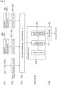
- the absorbance measuring device 10 includes a stage 3 in which containing unit groups 3 1 to 3 n in each of which one or more containing units that contain one or more kinds of chemical substance solutions, and a reaction container are arrayed in such a manner as to be extended in a Y-axis direction (column direction) are arrayed in an X-axis direction (row direction), and a nozzle head 5 including a suction/discharge mechanism 41 that sucks/discharges gas, a plurality of nozzles 4 1 to 4 n that communicates with the suction/discharge mechanism 41 and that is arrayed in the X-axis direction at intervals corresponding to the array of the containing unit groups, and one or more flow tubes 2 1 to 2 n each of which includes at a lower end a mouth part 2a, which can suck/discharge liquid and which can be simultaneously inserted into each of the containing units or the reaction container in each of the containing unit groups, and includes at an upper end an opening part for
- the absorbance measuring device 10 includes a nozzle moving mechanism (51, 42) that can relatively move the nozzles 4 1 to 4 n with respect to the stage 3, one or more emitting ends 6 1 to 6 n that can emit one or more kinds of measurement light to at least one of the flow tubes 2 1 to 2 n in such a manner as to pass through the flow tubes 2 1 to 2 n , a light source 62 that is optically connected to the emitting ends, one or more light receiving ends 7 1 to 7 n that can receive the light from the emitting ends 6 1 to 6 n , and a photoelectric conversion unit 72 that is optically connected to the light receiving ends 7 1 to 7 n and that converts intensity of received light into an electric signal.
- a nozzle moving mechanism 51, 42
- the absorbance measuring device 10 includes a nozzle moving mechanism (51, 42) that can relatively move the nozzles 4 1 to 4 n with respect to the stage 3, one or more emitting ends 6 1 to 6 n that can emit one or more kinds of measurement light to at least
- One of a group of the emitting ends 6 1 to 6 n and a group of the light receiving ends 7 1 to 7 n is provided on a common vertical axis passing through both of the mouth part 2a and the opening part for attachment 2b of each of the flow tubes 2 1 to 2 n attached to the nozzles and is provided in the nozzles or the suction/discharge mechanism on an upper side thereof, respectively.
- the other of the group of the emitting ends 6 1 to 6 n and the group of the light receiving ends 7 1 to 7 n is provided in the stage 3 in such a manner that the mouth parts 2a of the flow tubes 2 1 to 2 n can be placed on an upper side thereof, respectively.
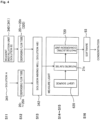
- the absorbance measuring device 10 includes a CPU + memory + program 9 that performs information processing as a control unit that controls the nozzle moving mechanism (51, 42), the suction/discharge mechanism 41, the light source 62, and the like and that calculates one or more kinds of chemical substance concentration, and an operation panel 94 on which operation such as an instruction by a user with respect to the CPU + memory + program 9 is performed.
- a CPU + memory + program 9 that performs information processing as a control unit that controls the nozzle moving mechanism (51, 42), the suction/discharge mechanism 41, the light source 62, and the like and that calculates one or more kinds of chemical substance concentration, and an operation panel 94 on which operation such as an instruction by a user with respect to the CPU + memory + program 9 is performed.
- the CPU + memory + program 9 performs control of sucking a prescribed amount of each of the chemical substance solutions independently or in a mixed manner into the flow tubes 2 1 to 2 n , placing the mouth parts 2a on the common vertical axis and on an upper side of the other of the group of the emitting ends 6 1 to 6 n and the group of the light receiving ends 7 1 to 7 n , and calculating the absorbance on the basis of intensity of transmitted light acquired by emission of the measurement light into the flow tubes.
- one of a column of the emitting ends 6 1 to 6 n that can emit the measurement light through the flow tubes and a column of the light receiving ends 7 1 to 7 n that can receive the light from the emitting ends is provided in a part 44 on the common vertical axis in the suction/discharge mechanism 41 or the nozzles 4 1 to 4 n in the nozzle head 5 (such as leading end of nozzle 4 1 to 4 n or leading end of plunger of cylinder), and the other is provided in the stage 3 in a manner of being arrayed in the X-axis direction.
- control is performed in such a manner that pairs of the light receiving ends 7 1 to 7 n and the emitting ends 6 1 to 6 n (pair of same subscript number) are placed on the common vertical axis through the flow tubes 2 1 to 2 n attached to the nozzles 4 1 to 4 n .
- Each of the light receiving ends 7 1 to 7 n or the emitting ends 6 1 to 6 n provided in the part 44 on the common vertical axis in the nozzles 4 1 to 4 n or the suction/discharge mechanism 41 is optically connected to the photoelectric conversion unit 72 or the light source 62 by a flexible light guiding path 71 (61).
- the light source 62, the emitting ends 6 1 to 6 n , and the light guiding path 61 correspond to an emission unit 6
- the photoelectric conversion unit 72 and the light receiving ends 7 1 to 7 n correspond to a light receiving unit 7.
- a nozzle moving unit 42 that moves the nozzles 4 1 to 4 n simultaneously in a Z-axis direction, a magnetic force mechanism 43 that can apply magnetic force to the inside of the flow tubes 2 1 to 2 n attached to the nozzles 4 1 to 4 n , and a detachment mechanism 45 that can simultaneously detach the flow tubes 2 1 to 2 n from the nozzles 4 1 to 4 n are further provided.
- a combination of the nozzle moving unit 42 that can move the nozzles 4 1 to 4 n in the Z-axis direction and the nozzle head moving mechanism 51 that can move the nozzle head 5 in the Y-axis direction and the X-axis direction corresponds to the nozzle moving mechanism (51, 42).
- a CPU + program + memory 9 includes an extraction/reaction control unit 91 that gives an instruction of extraction or reaction to the nozzle moving mechanism (51, 42), the suction/discharge mechanism 41, and the magnetic force mechanism 43, an absorption measurement control unit 92 that performs control of absorption measurement with respect to the nozzle moving mechanism (51, 42), the suction/discharge mechanism 41, the nozzle moving unit 42, the light source 62, and the photoelectric conversion unit 72, and an absorbance analysis unit 93 that leads absorbance of a chemical substance solution to be measured on the basis of intensity of transmitted light which intensity is acquired from the photoelectric conversion unit 72.
- the containing unit groups 3 1 to 3 n in the stage 3 respectively include one or more liquid containing units 34 1 to 34 n containing one or more kinds of chemical substance solutions, dispensing flow tube containing units 32 1 to 32 n in each of which a dispensing flow tube used as a dispensing chip is contained with an opening part for attachment being on an upper side in such a manner that attachment to the nozzles become possible, photometric flow tube containing units 33 1 to 33 n in each of which a photometric flow tube that performs measurement of light absorption is contained with an opening part for attachment being on an upper side in such a manner that attachment to the nozzles becomes possible, and reaction containers 31 1 to 31 n in which temperature control is possible.
- the absorbance measuring device 11 is embedded in a chassis having a function of a dark box that can block intrusion of light from the outside when necessary, and a touch-type tablet (not illustrated) corresponding to the operation panel 94 is provided outside the chassis.
- Each well in the microplate 310 is a reaction container in which temperature control can be performed, a chemical substance solution to be a measurement object of concentration is contained in the microplate 341, and the microplate 342 is a well for mixing solutions.
- These microplates 310, 341, and 342, photometric flow tube containing unit 330, and the like are provided in a manner of being loadable to and removable from the absorbance measuring device 11.
- a sign 370 is a disposal box that can store liquid or a flow tube disposed to the disposal vent 371 and that is provided in a manner of being loadable to and removable from the absorbance measuring device 11.
- the absorbance measuring device 11 includes a nozzle head 50 in which a plurality of (eight in this example) nozzles 40 1 to 40 n is arrayed in the X-axis direction, and a nozzle head moving mechanism 510 that can relatively move the nozzle head 50 in the Y-axis direction and the X-axis direction with respect to the stage 30.
- the nozzle head 50 includes a suction/discharge mechanism 410 that sucks/discharges gas, the eight nozzles 40 1 to 40 n that communicate with the suction/discharge mechanism 410, sixteen flow tubes 20 1 to 20 n , and 21 1 to 21 n including, at lower ends, mouth parts 20a and 21a that can suck/discharge liquid and that can be inserted into the containing units and including, at upper ends, opening parts for attachment 20b and 21b which parts can be detachably attached to the nozzles 40 1 to 40 n , a nozzle moving unit 420 that can move the nozzles 40 1 to 40 n simultaneously in the Z-axis direction with respect to the stage 30, a magnetic force mechanism 430 which can simultaneously apply or remove magnetic force to or from the inside of the flow tubes 20 1 to 20 n attached to the nozzles 40 1 to 40 n and in which a magnet is provided in a manner of being retractable with respect to the flow tubes 20 1 to 20 n , a de
- the nozzle head moving mechanism 510 includes a Y-axis moving mechanism 51y including a rail 512 laid in the Y-axis direction on the stage 30, a timing belt 513 bridged to a rotor 514 in the Y-axis direction, and a nozzle head supporting Y-axis moving body 515 that can be moved in the Y-axis direction by the timing belt 513, and an X-axis moving mechanism 51x provided in such a manner as to be able to move the nozzle head 50 in the X-axis direction to the nozzle head supporting Y-axis moving body 515.
- a sign 511 is a motor that drives a timing belt as the X-axis moving mechanism 51x.
- an information processing device corresponding to the CPU + memory + program 9 is also embedded in a downside of the stage 30.
- the nozzle moving unit 420 includes a motor 421, a rotor 422 rotationally driven by the motor 421, a timing belt 424 bridged between the rotor 422 and a rotor 423, and a ball screw 425 that is laid in the Z-axis direction and is rotationally driven by the rotor 423.
- a Z-axis moving body 42z including a nozzle supporting substrate 40 that supports the nozzles coupled to a nut part screwed to the ball screw 425 is moved upward/downward.
- the Z-axis moving body 42z of the nozzle head 50 further includes a suction/discharge mechanism 410
- the suction/discharge mechanism 410 includes a motor 412, a ball screw 413 rotationally driven by the motor 412, a plunger driving plate 415 coupled to a nut part screwed to the ball screw 413, and a plurality of (eight in this example) plungers 411 that is coupled to the plunger driving plate 415 and that is provided in a manner of being slidable in a plurality of (eight in this example) cylinders 416.
- An optical fiber 610 as a flexible light guiding path is provided in a piercing manner in a plunger 411 that slides in one cylinder 416 that communicates with at least one nozzle such as a nozzle 40 6 in the eight nozzles.
- a leading end of the optical fiber 610 is provided to an emitting end 60 6 at a leading end part 414 of the plunger 411 and a rear end thereof reaches a light source 620.
- the emitting end 60 6 , the optical fiber 610, and the light source 620 correspond to an emission unit 60.
- a lower end part of the cylinder 416 communicates with the nozzle 40 6 , and a photometric flow tube 21 6 is detachably attached to the nozzle 40 6 .
- the photometric flow tube 21 6 or a dispensing flow tube 20 6 includes a mouth part 20a that is provided at a lower end and that can suck/discharge liquid, an opening part for attachment 20b, 21b that can be attached to the nozzle 40 6 , a narrow tube part 21c (20c) including the mouth part at a lower end, and a wide tube part 21d (20d) that is formed to be wider than the narrow tube part and that includes the opening part for attachment 20b, 21b at an upper end.
- a sign 21e (20e) is a protrusion that is protruded from the wide tube part 21d (20d) in an outer direction and that is provided in a manner of being detachable from the nozzle by a flow tube detachment plate 450 (described later).
- the narrow tube part and the wide tube part are preferably painted with a black paint or formed of a black substance.
- a cylinder containing box 417 that is supported by the plunger driving plate 415 and that is provided in such a manner as to be able to move the flow tube detachment plate 450 in a lower direction by pushing a detaching stick by downward movement of the plunger driving plate 415 for a predetermined distance or more are included.
- a lower end of the detaching stick is attached to the flow tube detachment plate 450.
- the flow tube detachment plate 450 is supported in a state of being elastically biased to an upper side at all times.
- An upper end of the detaching stick is at a position separated from the plunger driving plate 415 for the predetermined distance.
- a light receiving unit 70 is provided in the stage 30.
- the light receiving unit 70 includes a hole 74 provided in a stage substrate 73, a lens of a light receiving end 70 6 provided on a downside of the hole 74, and a photoelectric conversion unit 720 that includes an ADP as a light receiving element provided on a lower side of the lens, a CCD image sensor, a photomultiplier tube (PMT), and the like.
- the light source 620 is provided in the nozzle head 50, and the light source 620 is optically connected, via the optical fiber 610, to the emitting end 60 6 at the leading end part 414 of the plunger 411 that slides in the cylinder 416.
- a deuterium lamp is used as the light source 620.
- step S1 for example, 0.022 ⁇ M of a chemical substance solution A to be measured (such as dNTP mixture, Takara Bio Inc., Code: 4030, Lot: BH7301B) is previously contained in one well (for example, in sixth column in first row) of the microplate 341 provided on the stage 30 of the absorbance measuring device 11, and a reference solution C (such as TE, 10 mM Tris-HCl, 1 mM EDTA, pH 8.0) as a blank sample for reference measurement in which light is not absorbed is contained in one reagent tank (such as first tank in four tank) among the reagent tanks 340.
- a chemical substance solution A to be measured such as dNTP mixture, Takara Bio Inc., Code: 4030, Lot: BH7301B
- a reference solution C such as TE, 10 mM Tris-HCl, 1 mM EDTA, pH 8.0
- a dispensing flow tube 20 6 is contained in one flow tube containing unit in the sixth column in the first row of the dispensing flow tube containing unit group 320 and that a dispensing flow tube 20 6 is also contained in one flow tube containing unit in the sixth column in the second row. Note that a description of processing using a dispensing flow tube is omitted.
- step S2 the nozzle head 50 is moved to an upper side of the second column in the first row of the photometric flow tube containing unit group 330 by the nozzle head moving mechanisms 51x and 51y and the nozzle 40 6 is moved downward by the nozzle moving unit 420, whereby a photometric flow tube 21 6 (for example, formed by molding of olefin-based resin such as polypropylene or polyethylene to which resin pigment such as carbon black is kneaded) is attached to the nozzle 40 6 .
- a photometric flow tube 21 6 for example, formed by molding of olefin-based resin such as polypropylene or polyethylene to which resin pigment such as carbon black is kneaded
- the photometric flow tube 21 6 is placed above the first reagent tank in the four reagent tanks 340 by the nozzle head moving mechanisms 51x and 51y and is moved downward by the nozzle moving unit 420, around 10 mm (around 7.6 ⁇ L) of a prescribed amount of the reference solution C is sucked from a leading end of the photometric flow tube by the suction/discharge mechanism 410, and a liquid lower end surface of the chemical substance solution A is placed in a predetermined distance such as 5 mm above the mouth part.
- the photometric flow tube 21 6 of the nozzle head 50 is lifted again and is placed on an upper side of the lens provided at the light receiving end 70 6 of the light receiving unit 70 of the stage 30 in such a manner that the emitting end 60 6 provided at a lower end of the plunger 411 that slides in the cylinder 416 coupled to the nozzle 40 6 and the lens provided at the light receiving end 70 6 is on a common vertical axis connecting an mouth part 21a and an opening part for attachment 21b of the photometric flow tube 21 6 and that the lens provided at the light receiving end 70 6 is in a predetermined distance (such as 10 mm) below the mouth part 21a.
- a predetermined distance such as 10 mm
- step S3 measurement light, for example, in a range of wavelengths 200 to 850 nm is emitted from the emitting end 60 6 to the solution C in the photometric flow tube 21 6 , and intensity of transmitted light of the solution C which light is received through the lens provided at the light receiving end 70 6 is converted into intensity data I 0 as an electric signal by the photoelectric conversion unit 720, subtracted from a measurement value of a sample, and used as reference data to calculate absorbance of the sample.
- the photometric flow tube is disposed from the disposal vent 371 into the disposal box 370 by the detachment member 450.
- step S4 the nozzle head 50 is moved to an upper side of the second column in the second row of the photometric flow tube containing unit group 330 by the nozzle head moving mechanisms 51x and 51y and the nozzle 40 6 is moved downward by the nozzle moving unit 420, whereby a new photometric flow tube 21 6 formed of the black substance is attached to the nozzle 40 6 .
- the photometric flow tube 21 6 is placed above the well in the sixth column in the first row of the microplate 341 by the nozzle head moving mechanisms 51x and 51y and is moved downward by the nozzle moving unit 420, a prescribed amount of the chemical substance solution A is sucked by the suction/discharge mechanism 410, and a liquid lower end surface of the chemical substance solution A is placed in a predetermined distance such as 5 mm above the mouth part.
- the photometric flow tube 21 6 of the nozzle head 50 is lifted again and is placed on an upper side of the lens provided at the light receiving end 70 6 of the light receiving unit 70 of the stage 30 in such a manner that the emitting end 60 6 provided at the lower end of the plunger 411 that slides in the cylinder 416 coupled to the nozzle 40 6 and the lens provided at the light receiving end 70 6 are on a common vertical axis connecting a mouth part 20a and an opening part for attachment 20b of the photometric flow tube 21 6 and that the lens provided at the light receiving end 70 6 is in a predetermined distance (such as 10 mm) below the mouth part 20a.
- a predetermined distance such as 10 mm
- Measurement light at a wavelength in a range of 200 to 850 nm is serially emitted from the emitting end 60 6 to the solution A in the photometric flow tube 21 6 , and intensity of transmitted light of the solution A which light is received through the lens provided at the light receiving end 70 6 is converted into intensity data I as an electric signal by the photoelectric conversion unit 720.
- step S5 the absorbance analysis unit 93 of the CPU + program + memory 9 as the control unit acquires absorbance of the chemical substance solution A on the basis of the intensity data I 0 and the intensity data I.
- a wavelength and absorbance in the range of 200 to 850 nm are calculated, and an average value of absorbance in 350 to 700 nm is calculated for each piece of data and subtracted from the absorbance in 200 to 850 nm for correction of a baseline.
- the concentration c is 45 to 46 mg/ ⁇ L.
- a purification degree of purified DNA can be evaluated by A 260 /A 230 and A 260/ A 280 . When a value of the former is 1.4 or larger and a value of the latter is 1.8 or larger, there is no problem in the purification degree.
- step S11 for example, 0.022 ⁇ M of a chemical substance solution A to be measured (such as dNTP mixture, Takara Bio Inc., Code: 4030, Lot: BH7301B) is previously contained in one well (for example, in sixth column in second row) of the microplate 341 provided on the stage 30 of the absorbance measuring device 11, and a prescribed amount of a solution B (such as bromophenol blue (BPB, blue pigment)) as an internal standard is contained, for example, in a second reagent tank in the four reagent tanks 340.
- a chemical substance solution A to be measured such as dNTP mixture, Takara Bio Inc., Code: 4030, Lot: BH7301B
- a solution B such as bromophenol blue (BPB, blue pigment)
- a dispensing flow tube 20 6 is contained in one flow tube containing unit in the sixth column in the third row of the dispensing flow tube containing unit group 320 and that ta dispensing flow tube 20 6 is also contained in one flow tube containing unit in the sixth column in the fourth row.
- step S12 the nozzle head 50 is moved to an upper side of the sixth column in the third row of the dispensing flow tube containing unit group 320 by the nozzle head moving mechanisms 51x and 51y and the nozzles 40 1 to 40 n is moved downward by the nozzle moving unit 420, whereby the flow tube 20 1 is attached to the one nozzle 40 1 .
- the attached flow tube 20 1 is moved to the sixth column in the second row of the microplate 341 by the nozzle head moving mechanisms 51x and 51y. After the flow tube is moved downward into the liquid containing unit, a prescribed amount is sucked into the flow tube 20 1 by the suction/discharge mechanism 410.
- the sucked solution A is discharged into a well in the sixth column in the first row of the microplate 342.
- the flow tube 20 1 is disposed from the disposal vent 371 into the disposal box 370 by the detachment member 450.
- step S13 the nozzle head 50 is moved again to an upper side of the sixth column in the fourth row of the dispensing flow tube containing unit group 320 by the nozzle head moving mechanisms 51x and 51y and the nozzles 40 1 to 40 n are moved downward by the nozzle moving unit 420, whereby a new flow tube 20 6 is attached to one of the nozzles 40 1 to 40 n .
- the attached flow tube 20 6 is moved to an upper side of the second one of the reagent tanks 340 by the nozzle head moving mechanisms 51x and 51y and the flow tube 20 6 is moved downward by the nozzle moving unit 420, whereby a prescribed amount of the solution B as an internal standard solution is sucked by the suction/discharge mechanism 410.
- the sucked solution B is discharged into the well in the sixth column in the first row of the microplate 342 and the solution A and the solution B are mixed. Agitation is performed by repetition of suction and discharge.
- the flow tube is disposed from the disposal vent 371 into the disposal box by the detachment member 450.
- step S14 the nozzle head 50 is moved to an upper side of the second column in the third row of the photometric flow tube containing unit group 330 by the nozzle head moving mechanisms 51x and 51y and the nozzle 40 6 is moved downward by the nozzle moving unit 420, whereby a photometric flow tube 21 6 (for example, formed by molding of olefin-based resin such as polypropylene or polyethylene to which resin pigment such as carbon black is kneaded) is attached to the nozzle 40 6 .
- a photometric flow tube 21 6 for example, formed by molding of olefin-based resin such as polypropylene or polyethylene to which resin pigment such as carbon black is kneaded
- the photometric flow tube 21 6 is placed above the well in the sixth column in the first row of the microplate 342 by the nozzle head moving mechanisms 51x and 51y and moved downward by the nozzle moving unit 420, a prescribed amount a solution AB is sucked by the suction/discharge mechanism 410, and a liquid lower end surface of the chemical substance solution A is placed in a predetermined distance such as 5 mm above the mouth part.
- the photometric flow tube 21 6 of the nozzle head 50 is lifted again and is placed on an upper side of the lens provided at the light receiving end 70 6 of the light receiving unit 70 on the stage 30 in such a manner that the emitting end 60 6 provided at the lower end of the plunger 411 that slides in the cylinder 416 coupled to the nozzle 40 6 and the lens provided at the light receiving end 70 6 are on a common vertical axis connecting a mouth part 20a and an opening part for attachment 20b of the photometric flow tube 21 6 and that the lens provided at the light receiving end 70 6 is in a predetermined distance (such as 10 mm) below the mouth part 20a.
- a predetermined distance such as 10 mm
- step S15 measurement light having an optimal wavelength in which light is absorbed by the solution A is emitted from the emitting end 60 6 to the solution AB in the photometric flow tube 21 6 , and intensity of transmitted light of the solution AB which light is received through the lens provided at the light receiving end 70 6 is converted into intensity data I as an electric signal by the photoelectric conversion unit 720 of the light receiving unit 70.
- Standard measurement light having an optimal wavelength which is different from the wavelength and in which light is absorbed by the solution B as the internal standard (such as wavelength around 260 nm in which light absorption is low) is simultaneously or serially emitted from the emitting end 60 6 to the solution AB in the photometric flow tube 21 6 , and intensity of transmitted light of the solution AB which light is received through the lens provided at the light receiving end 70 6 is converted into intensity data J as an electric signal by the photoelectric conversion unit 720.
- Fig. 5 is a flowchart of steps (S'11 to S'16) in a case where a plurality of kinds of chemical substance solutions (A to X) as concentration measurement objects in the microplate 341 or the reagent tanks 340 is measured.
- a nozzle head 15, and cartridge containers 13 1 to 13 8 as a containing unit group provided in a stage 13 according to an embodiment of the present invention will be described on the basis of Fig. 7 to Fig. 11 .
- Fig. 7 and Fig. 8 are views illustrating the nozzle head 15 provided instead of the nozzle head 50, and the cartridge containers 13 1 to 13 8 respectively including, as the containing unit group, at least a plurality of liquid containing units and reaction containers in the absorbance measuring device 11 illustrated in Fig. 2 .
- the cartridge containers 13 1 to 13 8 are provided instead of the reagent tanks 340 and the microplates 341 and 342 in the stage 30 illustrated in Fig. 2 .
- cartridge containers (not illustrated) as a flow tube containing unit group to contain a flow tube are further arrayed, in the stage 13, in an X-axis direction at intervals of rows of the cartridge containers 13 1 to 13 8 instead of the (dispensing and photometric) flow tube containing unit groups 320 and 330.
- a nozzle moving mechanism and the like except for what will be newly described in the following such as a suction/discharge mechanism or the like provided in the nozzle head 15, and a light receiving end or the like provided in the stage.
- the nozzle head 15 includes a suction/discharge mechanism 141.
- suction/discharge mechanism 141 suction/discharge units 141 1 to 141 8 including a plurality of (eight in this example) cylinders are provided and arrayed in an X-axis direction, and nozzles 14 1 to 14 8 that communicates with the cylinders are provided at a lower end thereof in a manner of being protruded to a lower side.
- the nozzle head 15 includes eight photometric flow tubes 21 1 to 21 8 including, at lower ends, mouth parts 21a that can suck/discharge liquid and that can be inserted into the containing units and including, at upper ends, opening parts for attachment 21b detachably attached to the nozzles 14 1 to 14 8 .
- the stage 13 includes the cartridge containers 13 1 to 13 8 as a containing unit group in eight columns.
- Each of the suction/discharge units 141 1 to 141 8 of the suction/discharge mechanism 141 includes a cylinder inside, and a plunger provided in a manner of being slidable in an inner side thereof (see, for example, Fig. 3 ).
- the plurality of (eight in this example) nozzles 14 1 to 14 8 is respectively provided at lower ends of the cylinders.
- Optical fibers 161 are respectively provided through the inside of the nozzles 14 1 to 14 8 .
- Leading ends of the optical fibers 161 are respectively provided at emitting ends 16 1 to 16 8 and on common vertical axes of the flow tubes 21 1 to 21 8 at lower ends of the nozzles 14 1 to 14 8 .
- Rear ends of the optical fibers 161 are provided as first connection ends 161a and are arrayed at equal intervals along a first straight line on a connection surface of connection end array plates 18 1 to 18 8 .
- ten liquid containing units 134, reaction containers 131 and 133 in which a temperature can be controlled, and a photometric container 8 are arrayed in one column in a Y-axis direction in each of the cartridge containers 13 1 to 13 8 in the stage 13.
- Light receiving ends 17 1 to 17 8 each of which includes a leading end of an optical fiber 171 are provided on a lower side of the photometric container 8 and on a downside of the stage 13.
- Rear ends of the optical fibers 171 are optically connected to spectroscopes 172 1 to 172 8 and the leading ends thereof are optically connected to the spectroscopes 172 1 to 172 8 .
- the rear ends are provided as second connection ends 171a and are arrayed at equal intervals along a second straight line on the connection surface of the connection end array plates 18 1 to 18 8 .
- the second straight line is extended in parallel with the first straight line at a predetermined interval.
- a measurement end moving device 181 slidable in the X-axis direction is included, and a first measurement end and a second measurement end that are respectively moved along the first straight line and the second straight line and that can be serially and respectively connected to the first connection end 161a and the second connection end 171a are respectively provided along the first straight line and the second straight line at the predetermined interval.
- the first measurement end is optically connected to a light source 620 via a light guiding path such as an optical fiber
- the second measurement end is optically connected to a photoelectric conversion unit 720 via a light guiding path such as an optical fiber.
- connection end array plates 18 1 to 18 8 and the measurement end moving device 181 correspond to a switching unit 18 including the emission switching unit and the light-reception switching unit that respectively switch connection between a plurality of (eight in this example) emitting ends and one light source and connection between a plurality of (eight in this example) light receiving ends and one photoelectric conversion unit 720.
- the spectroscopes 172 1 to 172 8 are devices to extract transmitted light at a designated wavelength from transmitted light of the chemical substance solution, which light is received at the light receiving ends 17 1 to 17 8 , by using dispersion by a diffraction grating or a prism, and are set, for example, to a wavelength of designated measurement light. Accordingly, even when measurement light is white light, it is possible to guide transmitted light at a predetermined wavelength or in a predetermined wavelength region to a light receiving unit, to measure intensity thereof, and to measure absorbance at the predetermined wavelength or in the predetermined wavelength region.
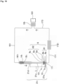
- Fig. 10 and Fig. 11 are views illustrating an outline of an optical system and a usage state of the photometric container 8 according to the present embodiment.
- the photometric container 8 is provided in the stage 13 as one of liquid containing units of each of the cartridge containers 13 1 to 13 8 , includes a bottom part 8c which is close to an upper side of the light receiving ends 17 1 to 17 n and in which a translucent region having translucency with respect to the measurement light is formed, and includes a tubular recessed part 81 to which a lower end part of each of light-blocking photometric flow tubes 21 1 to 21 8 , which are the flow tubes to which a black pigment is kneaded, can be inserted or loosely inserted from an upper side and which is formed at a center of the bottom part 8c.
- the translucent region is formed in a narrow bottom part 8a of the recessed part 81.
- a narrow sidewall part 8b of the recessed part 81 is formed to have a light blocking effect with respect to outside light with a black pigment being kneaded in molding.
- a sign 8d indicates a sidewall part
- 8e indicates a substrate of each of the cartridge containers 13 1 to 13 8
- a sign 82 indicates a tubular liquid containing unit (well) which is formed in each of the cartridge containers 13 1 to 13 8 and at a center of which the recessed part 81 is formed.
- the recessed part 81 is provided in such a manner as to be loosely inserted into a hole provided in a plate of the stage 13. Also, a state in which a lower end part of a narrow tube part 21c of a photometric flow tube 21 1 as the flow tube is inserted into the recessed part 81 and a mouth part 21a is abutted to the narrow bottom part 8a in the photometric container 8 is illustrated.
- step S'1 for example, 0.022 ⁇ M of a chemical substance solution A to be measured (such as dNTP mixture, Takara Bio Inc., Code: 4030, Lot: BH7301B) is previously contained in one well (for example, in first row) of each of the cartridge containers 13 1 to 13 8 provided on the stage 13 of the absorbance measuring device 11, and a reference solution C (such as TE, 10 mM Tris-HCl, 1 mM EDTA, pH 8.0) as a blank sample for reference measurement in which light is not absorbed is contained in a different well (for example, in second row).
- a chemical substance solution A to be measured such as dNTP mixture, Takara Bio Inc., Code: 4030, Lot: BH7301B
- a reference solution C such as TE, 10 mM Tris-HCl, 1 mM EDTA, pH 8.0
- dispensing flow tubes 20 1 to 20 8 are contained in flow tube containing units in the first and second rows of the different cartridge container of a flow tube containing unit group (not illustrated) and that photometric flow tubes 21 1 to 21 8 are contained in flow tube containing units in the third and fourth rows. Note that a description of processing of using a dispensing flow tube before using a photometric flow tube is omitted.
- step S'2 the nozzle head 15 is moved to an upper side of the third row of each of the different cartridge containers (flow tube containing unit) by the nozzle head moving mechanisms 51x and 51y and the nozzles 14 1 to 14 8 are moved downward by the nozzle moving unit 420, whereby the photometric flow tubes 21 1 to 21 8 formed of a black substance (for example, formed by molding of olefin-based resin such as polypropylene or polyethylene to which resin pigment such as carbon black is kneaded) are attached to the nozzles 14 1 to 14 8 .
- a black substance for example, formed by molding of olefin-based resin such as polypropylene or polyethylene to which resin pigment such as carbon black is kneaded
- the photometric flow tubes 21 1 to 21 8 are placed above the wells in the second row of the cartridge containers 13 1 to 13 8 by the nozzle head moving mechanisms 51x and 51y and are moved downward by the nozzle moving unit 420, and around 10 mm (around 7.6 ⁇ L) of a prescribed amount of the reference solution C is sucked from a leading end of each of the photometric flow tubes by the suction/discharge mechanism 141.
- the photometric flow tubes 21 1 to 21 8 of the nozzle head 15 are placed by the nozzle head moving mechanisms 51x and 51y on an upper side of the photometric container 8 provided on an upper side of the light receiving ends 17 1 to 17 8 of the light receiving unit 70 in the stage 13 in such a manner that the recessed part 81 of each of the photometric containers 8 is on a common vertical axis connecting a mouth part 21a and an opening part for attachment 21b of each of the photometric flow tubes 21 1 to 21 8 and that the light receiving ends 17 1 to 17 8 are on a lower side of the mouth parts 21a.
- the photometric flow tubes are simultaneously moved downward by the nozzle moving unit 420, whereby each of the leading end parts of the photometric flow tubes is inserted into the recessed part 81 and a mouth part 21a is abutted to the narrow bottom part 8a.
- step S'3 measurement light, for example, in a range of wavelengths 200 to 850 nm is emitted from the emitting ends 16 1 to 16 8 to the solution C in the photometric flow tubes 21 1 to 21 8 , and intensity of transmitted light of the solution C which light is received through a lens provided at each of the light receiving ends is converted into intensity data I 0 as an electric signal by the photoelectric conversion unit 720, subtracted from a measurement value of a sample, and used as reference data to calculate absorbance of the sample.
- the photometric flow tube is disposed from the disposal vent 371 into the disposal box 370 by the detachment member 450.
- the mouth parts 21a of the photometric flow tubes 21 1 to 21 8 are abutted to the narrow bottom parts 8a in such a manner that an air layer is not included in an upper side of the mouth parts 21a in the photometric flow tubes 21 1 to 21 8 .
- step S'4 the nozzle head 15 is moved to an upper side of the fourth row of the flow tube containing units by the nozzle head moving mechanisms 51x and 51y and the nozzles 14 1 to 14 8 are moved downward by the nozzle moving unit 420, whereby new photometric flow tubes 21 1 to 21 8 (for example, formed by molding of olefin-based resin such as polypropylene or polyethylene to which resin pigment such as carbon black is kneaded) are attached to the nozzles 14 1 to 14 8 .
- new photometric flow tubes 21 1 to 21 8 for example, formed by molding of olefin-based resin such as polypropylene or polyethylene to which resin pigment such as carbon black is kneaded
- the photometric flow tubes 21 1 to 21 8 are placed above the wells in the first row of the cartridge containers 13 1 to 13 8 by the nozzle head moving mechanisms 51x and 51y and are moved downward by the nozzle moving unit 420, and a prescribed amount of the chemical substance solution A is sucked by the suction/discharge mechanism 410.
- the photometric flow tubes 21 1 to 21 8 of the nozzle head 15 are placed by the nozzle head moving mechanisms 51x and 51y on an upper side of cleaned photometric containers 8 provided on an upper side of the light receiving ends 17 1 to 17 8 in the stage 13 in such a manner that the recessed part 81 of each of the photometric containers 8 is on a common vertical axis connecting a mouth part 21a and an opening part for attachment 21b of each of the photometric flow tubes 21 1 to 21 6 and that the light receiving ends 17 1 to 17 8 are on a lower side of the mouth parts 21a.
- the photometric flow tubes 21 1 to 21 8 are simultaneously moved downward by the nozzle moving unit 420, whereby leading end parts 21a of the photometric flow tubes 21 1 to 21 8 are loosely inserted into the recessed parts 81 and the mouth parts 21a are abutted to the narrow bottom parts 8a.
- the mouth parts 21a of the photometric flow tubes 21 1 to 21 8 are abutted to the narrow bottom parts 8a with a part of the solution being contained in the recessed parts in such a manner that an air layer is not included in an upper side of the mouth parts 21a in the photometric flow tubes 21 1 to 21 8 .
- the narrow bottom parts 8a are close to or appressed to light receiving end surfaces of the light receiving ends 17 1 to 17 8 .
- positioning is securely performed by loose insertion or insertion of each of the photometric flow tubes 21 1 to 21 8 into the recessed part 81, and movement of a solution through the mouth part 21a is prevented by removal of an air layer from an upper end surface of liquid to a light receiving end surface, whereby it becomes possible to acquire a stable optical length L.
- Measurement light at a wavelength in a range of 200 to 850 nm is serially emitted from the emitting ends 16 1 to 16 8 to a solution A in the photometric flow tube 21 6 , and intensity data I as an electric signal is acquired by the photoelectric conversion unit 720 from intensity of transmitted light of the solution A which light is received through light receiving ends 17 1 to 17 8 .
- step S'5 the absorbance analysis unit 93 of the CPU + program + memory 9 as the control unit acquires absorbance of the chemical substance solution A on the basis of the intensity data I 0 and the intensity data I.
- an emitting end is provided at a lower end of each of the nozzles or a lower end of a plunger, it is possible to securely guide emitted measurement light into a flow tube and to perform emission highly efficiently. Specifically, since a material opaque with respect to measurement light is used for a flow tube, it becomes possible to prevent leakage of the measurement light to the outside and to calculate highly accurate absorbance. It becomes possible to emit measurement light. Also, in a case where the photometric container is used, it is possible to securely place the emitting end and the light receiving end on the common vertical axis, to prevent movement of liquid through a mouth part, to remove an air layer, to accurately determine an optical length, and to acquire highly accurate absorbance.
- the photometric container even in a case where the photometric container is not used, by providing a void from a mouth part in a narrow tube of a flow tube, it is possible to prevent movement of a solution from the mouth part, to determine an optical length, and to acquire highly accurate absorbance.
- absorbance is measured with a spectroscope being used on a side of a light receiving unit in the above description.
- a spectroscope or a filter may be used on a side of an emission unit.
- a nucleic acid is a chemical substance to be measured in the above description.
- this case is not a limitation, and a different high-molecular substance such as an amino acid, protein, a sugar chain, or fat, a solid such as a magnetic body, or a chemical substance solution in various fluid volumes which solution includes various chemical substances and which solution is, for example, foam, gas, or liquid may be used.
- a shape, a structure, and a function of each of the configuration elements described above are not limited to an example described in an embodiment.
- a timing belt is used as a nozzle head moving mechanism and a ball screw is used as a nozzle moving unit has been described.
- a timing belt and a ball screw can be arbitrarily replaced and a similar configuration can be acquired even when a different mechanism is used.
- the present invention relates to an absorbance measuring device and a method thereof.
- the present invention relates to various fields that are fields requiring handling of a biopolymer or biological lowmolecular compound such as a gene, an immune system, an amino acid, protein, or sugar and are, for example, an industrial field, an agricultural field such as food, agroprocessing, or fish processing, a pharmaceutical field, a medical field such as sanitation, security of health, immunity, illness, or heredity, and a science field such as chemistry or biology.
- the present invention is specifically effective in a case where a series of processing using many reagents or substances is successively executed in predetermined order.
Landscapes
- Physics & Mathematics (AREA)
- Chemical & Material Sciences (AREA)
- Immunology (AREA)
- Pathology (AREA)
- Analytical Chemistry (AREA)
- Biochemistry (AREA)
- General Health & Medical Sciences (AREA)
- General Physics & Mathematics (AREA)
- Health & Medical Sciences (AREA)
- Life Sciences & Earth Sciences (AREA)
- Spectroscopy & Molecular Physics (AREA)
- Engineering & Computer Science (AREA)
- Chemical Kinetics & Catalysis (AREA)
- Plasma & Fusion (AREA)
- Optical Measuring Cells (AREA)
- Investigating Or Analysing Materials By Optical Means (AREA)
- Automatic Analysis And Handling Materials Therefor (AREA)
Claims (16)
- Absorptionsmessvorrichtung (10; 11), umfassend:eine oder mehrere Flüssigkeit enthaltende Einheiten (341 bis 34n), die eine zu messende Lösung chemischer Substanzen enthalten können;einen Ansaug-/Ablassmechanismus (41; 410; 141), der dazu ausgelegt ist, Gas anzusaugen/abzulassen, und einen oder mehrere Zylinder (416) und einen oder mehrere Kolben (411) aufweist; wobei der eine oder die mehreren Kolben (411) verschiebbar in dem einen oder den mehreren Zylindern (416) angeordnet sind,eine oder mehrere Düsen (41 bis 4n; 401 bis 40n; 141 bis 14n), die dazu ausgelegt sind, mit dem einen oder den mehreren Zylindern (416) des Ansaug-/Ablassmechanismus (41; 410; 141) zu kommunizieren;ein oder mehrere Strömungsrohre (21 bis 2n), die sich jeweils von einem unteren Ende zu einem oberen Ende erstrecken und einen Mündungsteil an dem unteren Ende, der dazu ausgelegt ist, in jede der Flüssigkeit enthaltenden Einheiten (341 bis 34n) eingeführt zu werden, und einen Öffnungsteil an dem oberen Ende, der dazu ausgelegt ist, abnehmbar an einer der Düsen (41 bis 4n; 401 bis 40n; 141 bis 14n) angebracht zu werden, umfassen;eine oder mehrere emittierende optische Fasern (161; 610), wobei jede emittierende optische Faser einen hinteren Abschnitt, der optisch mit einer Lichtquelle (620) verbunden ist, und einen vorderen Abschnitt, der an einem emittierenden Ende (61 bis 6n; 601 bis 60n; 161 bis 16n) endet, aufweist,wobei die optische Faser (161, 610) in dem Kolben (411), der innerhalb des einen oder der mehreren Zylinder (416) des Ansaug-/Ablassmechanismus (41; 410; 141) gleitet, auf durchstechende Weise bereitgestellt ist und das vordere Ende der optischen Faser (161, 610) dem emittierenden Ende (61 bis 6n; 601 bis 60n; 161 bis 16n) an einem vorderen Endteil (414) des Kolbens (411) bereitgestellt ist;wobei das emittierende Ende (61 bis 6n; 601 bis 60n; 161 bis 16n) dazu ausgelegt ist, Messlicht von der Lichtquelle (620) zu emittieren;eine oder mehrere empfangende optische Fasern (171), wobei jede empfangende optische Faser optisch mit einer photoelektrischen Umwandlungseinheit (72; 720) verbunden ist und dazu ausgelegt ist, Messlicht von dem emittierenden Ende (61 bis 6n; 601 bis 60n; 161 bis 16n) an einem lichtempfangenden Ende (71 bis 7n; 70n; 171 bis 17n) zu empfangen; undeine Steuereinheit, die an den Ansaug- und Ablassmechanismus, die Lichtquelle und die photoelektrische Umwandlungseinheit (72; 720) wirkgekoppelt ist, wobei die Steuereinheit zu Folgendem ausgelegt ist:Übertragen eines Signals an den Ansaug-/Ablassmechanismus (41; 410; 141), um eine oder mehrere vorgegebene Mengen der einen oder mehreren Lösungen chemischer Substanzen in das eine oder die mehreren Strömungsrohre anzusaugen;Übertragen eines Signals an die Lichtquelle (620), um das Messlicht von den emittierenden Enden (61 bis 6n; 601 bis 60n; 161 bis 16n) in einer vertikalen Richtung durch das eine oder die mehreren Strömungsrohre zu emittieren; undBestimmen eines oder mehrerer Absorptionswerte der einen oder mehreren Lösungen chemischer Substanzen auf Grundlage von einem oder mehreren Intensitätsdatensignalen, die von der photoelektrischen Umwandlungseinheit (72; 720) empfangen werden, wobei das eine oder die mehreren Intensitätsdatensignale auf einer oder mehreren Intensitäten des Messlichts basieren, das an den lichtempfangenden Enden (71 bis 7n; 70n; 171 bis 17n) empfangen wird.
- Absorptionsmessvorrichtung nach Anspruch 1, wobei die Vorrichtung ferner eine Plattform und einen Düsenbewegungsmechanismus (51) umfasst,wobei die Flüssigkeit enthaltenden Einheiten (341 bis 34n) und die empfangenden optischen Fasern (171) in der Plattform bereitgestellt sind,der Düsenbewegungsmechanismus (51) dazu ausgelegt ist, die Düsen (41 bis 4n; 401 bis 40n; 141 bis 14n) in Bezug auf die Plattform relativ zu bewegen, unddie Steuereinheit dazu ausgelegt ist, eine Steuerung der Absorptionsmessung der Lösung chemischer Substanzen in Bezug auf den Düsenbewegungsmechanismus (51) durch mindestens Steuern des Düsenbewegungsmechanismus (51) und des Ansaug-/Ablassmechanismus (41; 410; 141) durchzuführen.
- Absorptionsmessvorrichtung nach Anspruch 2, ferner umfassend eine Emissionsschalteinheit, die dazu ausgelegt ist, eine optische Verbindung zwischen dem einen oder den mehreren emittierenden Enden (61 bis 6n; 601 bis 60n; 161 bis 16n) und der einen oder den mehreren Lichtquellen (620) umzuschalten, oder eine Lichtempfangsschalteinheit, die dazu ausgelegt ist, eine optische Verbindung zwischen dem einen oder den mehreren lichtempfangenden Enden (71 bis 7n; 70n; 171 bis 17n) und der einen oder den mehreren photoelektrischen Umwandlungseinheiten (72; 720) umzuschalten.
- Absorptionsmessvorrichtung nach Anspruch 1 oder Anspruch 2, ferner umfassend mindestens einen Reaktionsbehälter (311 bis 31n),
wobei mindestens eine der Flüssigkeit enthaltenden Einheiten (341 bis 34n) ein photometrischer Behälter (8) ist, der einen Bodenteil beinhaltet, in dem ein durchscheinender Bereich ausgebildet ist, der für das Messlicht durchscheinend ist. - Absorptionsmessvorrichtung nach Anspruch 4, wobei die Strömungsrohre (21 bis 2n) aus einer schwarzen Substanz als ein lichtabblockendes Element ausgebildet sind,wobei ein unterer Endteil von jedem der Strömungsrohre (21 bis 2n) dazu ausgelegt ist, von einer oberen Seite in den unteren Teil (8c) des photometrischen Behälters (8) eingeführt oder lose eingeführt zu werden,wobei der untere Teil (8c) des photometrischen Behälters (8) einen röhrenförmigen vertieften Teil (81) beinhaltet, wobei von einer oberen Seite davon der untere Endteil von jedem der Strömungsrohre (21 bis 2n) eingeführt oder lose eingeführt werden kann und der in dem unteren Teil (8c) des photometrischen Behälters (8) ausgebildet ist,wobei der durchscheinende Bereich in einem unteren Teil (8a) des vertieften Teils (81) ausgebildet ist und ein Seitenwandteil (8b) des vertieften Teils (81) so ausgebildet ist, dass er eine lichtblockierende Wirkung in Bezug auf das Außenlicht aufweist.
- Absorptionsmessvorrichtung nach einem von Anspruch 1 bis Anspruch 4, wobei die Steuereinheit dazu ausgelegt ist, eine Steuerung auf eine solche Weise durchzuführen, dass die Lösung chemischer Substanzen an eine obere Seite einer Position angesaugt wird, die um einen bestimmten Abstand über jedem der Mündungsteile der Strömungsrohre (21 bis 2n) liegt, wobei in den Strömungsrohren (21 bis 2n), die eine Länge von 5 cm bis 20 cm aufweisen, der bestimmte Abstand 0,5 mm bis 10 mm beträgt.
- Absorptionsmessvorrichtung nach Anspruch 1, wobei zwei oder mehr Arten von Lösungen chemischer Substanzen jeweils in den zwei oder mehr Flüssigkeit enthaltenden Einheiten (341 bis 34n) enthalten sind,eine Art von Lösung chemischer Substanzen in der Vielzahl von Arten von Lösungen chemischer Substanzen eine Lösung eines internen Standards bekannter Konzentration ist,eine Art von Messlicht in der Vielzahl von Arten von Messlicht Standardmesslicht ist, das durch den internen Standard absorbiert werden kann, unddie emittierenden Enden (61 bis 6n; 601 bis 60n; 161 bis 16n) dazu ausgelegt sind, gleichzeitig oder nacheinander das Standardmesslicht und jede Art des Messlichts zu emittieren, wobei das Standardmesslicht eine Wellenlänge aufweist, die sich von der Wellenlänge unterscheidet, und wobei Licht durch die Lösung als der interne Standard absorbiert wird, unddie Steuereinheit dazu ausgelegt ist, auf eine solche Weise zu steuern, dass eine vorgegebene Menge von jeder der Lösungen chemischer Substanzen und eine vorgegebene Menge der Lösung eines internen Standards in der Flüssigkeit enthaltenden Einheit (341 bis 34n) gemischt und in die Strömungsrohre (21 bis 2n) angesaugt werden, jede Art von dem Messlicht und dem Standardmesslicht von den emittierenden Enden (61 bis 6n; 601 bis 60n; 161 bis 16n) in die Strömungsrohre (21 bis 2n) emittiert wird und eine Absorption jeder der Lösungen chemischer Substanzen auf Grundlage einer Intensität jeder Art von durchgelassenem Licht in Bezug auf das Messlicht und einer Intensität von durchgelassenem Licht in Bezug auf das Standardmesslicht, das an den lichtempfangenden Enden (71 bis 7n; 70n; 171 bis 17n) empfangen wird, erfasst wird.
- Absorptionsmessvorrichtung nach Anspruch 1, wobei zwei oder mehr Arten von Lösungen chemischer Substanzen jeweils in den zwei oder mehr Flüssigkeit enthaltenden Einheiten (341 bis 34n) enthalten sind,eine Art von Lösung chemischer Substanzen in der Vielzahl von Arten von Lösungen chemischer Substanzen ein Verdünnungsmittel ist unddie Steuereinheit dazu ausgelegt ist, auf eine solche Weise zu steuern, dass eine vorgegebene Menge von jeder der Lösungen chemischer Substanzen und eine vorgegebene Menge des Verdünnungsmittels in der Flüssigkeit enthaltenden Einheit (341 bis 34n) gemischt und in die Strömungsrohre (21 bis 2n) angesaugt werden, jede Art von dem Messlicht von den emittierenden Enden (61 bis 6n; 601 bis 60n; 161 bis 16n) in die Strömungsrohre (21 bis 2n) emittiert wird und eine Absorption der Lösungen chemischer Substanzen auf Grundlage einer Intensität jeder Art von durchgelassenem Licht in Bezug auf das Messlicht, wobei das durchgelassene Licht an den lichtempfangenden Enden (71 bis 7n; 70n; 171 bis 17n) empfangen wird, erfasst wird.
- Absorptionsmessverfahren, umfassend:Übertragen, durch eine Steuereinheit, eines Signals an einen Ansaug-/Ablassmechanismus (41; 410; 141), der einen oder mehrere Kolben (411) und einen oder mehrere Zylinder (416) aufweist, um eine oder mehrere vorgegebene Mengen einer oder mehrerer Lösungen chemischer Substanzen aus einer oder mehreren Flüssigkeit enthaltenden Einheiten (341 bis 34n) unter Verwendung einer oder mehrerer Düsen (41 bis 4n; 401 bis 40n; 141 bis 14n) anzusaugen, die mit dem einen oder den mehreren Zylindern (416) des Ansaug-/Ablassmechanismus (41; 410; 141) kommunizieren, wobei die eine oder mehreren Lösungen chemischer Substanzen in ein oder mehrere Strömungsrohre (21 bis 2n) angesaugt werden, die an die eine oder mehreren Düsen (41 bis 4n; 401 bis 40n; 141 bis 14n) gekoppelt sind, und wobei sich jedes Strömungsrohr von einem unteren Ende zu einem oberen Ende erstreckt und einen Mündungsteil an dem unteren Ende, der dazu ausgelegt ist, in jede der Flüssigkeit enthaltenden Einheiten (341 bis 34n) eingeführt zu werden, und einen Öffnungsteil an dem oberen Ende, der dazu ausgelegt ist, eine Düse abnehmbar aufzunehmen, umfasst;Übertragen, durch die Steuereinheit, eines Signals an eine Lichtquelle (620), um Messlicht von emittierenden Enden (61 bis 6n; 601 bis 60n; 161 bis 16n) einer oder mehrerer emittierender optischer Fasern (161; 610) in einer vertikalen Richtung zu emittieren,wobei jede emittierende optische Faser (161; 610) einen hinteren Abschnitt, der optisch mit der Lichtquelle (620) verbunden ist, und einen vorderen Abschnitt, der an dem emittierenden Ende (61 bis 6n; 601 bis 60n; 161 bis 16n) endet und in dem Kolben (411) auf durchstechende Weise bereitgestellt ist, aufweist,wobei das vordere Ende der optischen Faser (161, 610) dem jeden emittierenden Ende (61 bis 6n; 601 bis 60n; 161 bis 16n) an einem vorderen Endteil (414) des Kolbens (411) bereitgestellt ist, der innerhalb des einen oder der mehreren Zylinder (416) des Ansaug-/Ablassmechanismus (41; 410; 141) gleitet; undBestimmen, durch die Steuereinheit, eines oder mehrerer Absorptionswerte der einen oder mehreren Lösungen chemischer Substanzen auf Grundlage von einem oder mehreren Intensitätsdatensignalen, die von einer photoelektrischen Umwandlungseinheit (72; 720) empfangen werden, wobei das eine oder die mehreren Intensitätsdatensignale auf einer oder mehreren Intensitäten des Messlichts basieren, das an lichtempfangenden Enden (71 bis 7n; 70n; 171 bis 17n) einer oder mehrerer empfangender optischer Fasern empfangen wird, wobei jede empfangende optische Faser optisch mit der photoelektrischen Umwandlungseinheit (72; 720) verbunden ist.
- Absorptionsmessverfahren nach Anspruch 9, wobei die Flüssigkeit enthaltenden Einheiten (341 bis 34n) und die empfangenden optischen Fasern (141) in einer Plattform bereitgestellt sind und ein Düsenbewegungsmechanismus (51), der die Düsen (41 bis 4n; 401 bis 40n; 141 bis 14n) in Bezug auf die Plattform relativ bewegen kann, beinhaltet ist und
in dem Messlichtemittierungsschritt die Mündungsteile des einen oder der mehreren Strömungsrohre (21 bis 2n) auf der mit den empfangenden optischen Fasern (171) versehenen Plattform durch den Düsenbewegungsmechanismus (51) platziert werden und eine Emission in der vertikalen Richtung durch die Strömungsrohre (21 bis 2n) durchgeführt wird. - Absorptionsmessverfahren nach Anspruch 9 oder Anspruch 10,
wobei der Messlichtemittierungsschritt einen optischen Verbindungsumschaltschritt zum Umschalten einer optischen Verbindung zwischen dem einen oder den mehreren emittierenden Enden (61 bis 6n; 601 bis 60n; 161 bis 16n) und einer oder mehreren Lichtquellen (620) oder zwischen dem einen oder den mehreren lichtempfangenden Enden (71 bis 7n; 70n; 171 bis 17n) und einer oder mehreren photoelektrischen Umwandlungseinheiten (72; 720) beinhaltet. - Absorptionsmessverfahren nach einem von Anspruch 9 bis Anspruch 11, wobei in dem Ansaugschritt mindestens eine der Flüssigkeit enthaltenden Einheiten (341 bis 34n) oder ein Reaktionsbehälter ein photometrischer Behälter (8) ist, der einen Bodenteil (8c) beinhaltet, in dem ein durchscheinender Bereich mit Durchscheinbarkeit für das Messlicht ausgebildet ist, und eine Ansaugung in die Strömungsrohre (21 bis 2n) durch den Ansaug-/Ablassmechanismus (41; 410; 141) durchgeführt wird, wobei nur ein Teil einer Lösung chemischer Substanzen, die in dem photometrischen Behälter (8) enthalten ist, zurückbleibt, und
in dem Messlichtemittierungsschritt die Mündungsteile der Strömungsrohre (21 bis 2n) auf der mit den emittierenden optischen Fasern (161; 610) versehenen Plattform durch Anlage der Mündungsteile der Strömungsrohre (21 bis 2n) an den durchscheinenden Bereich in dem unteren Teil (8c) platziert werden und das Messlicht von den emittierenden Enden (61 bis 6n; 601 bis 60n; 161 bis 16n) in der vertikalen Richtung durch die Strömungsrohre (21 bis 2n) emittiert wird. - Absorptionsmessverfahren nach einem von Anspruch 9 bis Anspruch 11, wobei die Strömungsrohre (21 bis 2n) derart bereitgestellt sind, dass Außenlicht blockiert wird, wobei der photometrische Behälter (8) einen röhrenförmigen vertieften Teil (81) beinhaltet, wobei von einer oberen Seite davon ein unterer Endteil von jedem der Strömungsrohre (21 bis 2n) eingeführt oder lose eingeführt werden kann und der um eine Mitte des photometrischen Behälters (8) herum ausgebildet ist, wobei der durchscheinende Bereich in einem unteren Teil (8a) des vertieften Teils (81) bereitgestellt ist und ein Seitenwandteil (8b) des vertieften Teils (81) derart ausgebildet ist, dass er eine lichtblockierende Wirkung in Bezug auf das Außenlicht aufweist, und
in dem Messlichtemittierungsschritt die Strömungsrohre (21 bis 2n) zu einer oberen Seite des photometrischen Behälters (8) bewegt werden und das Messlicht von den emittierenden Enden (61 bis 6n; 601 bis 60n; 161 bis 16n) in der vertikalen Richtung durch die Strömungsrohre (21 bis 2n) in einem Zustand emittiert wird, in dem der untere Endteil von jedem der Strömungsrohre (21 bis 2n) in den vertieften Teil (81) eingeführt oder lose eingeführt ist und der Mündungsteil davon an dem unteren Teil (8a) anliegt. - Absorptionsmessverfahren nach einem von Anspruch 9 bis Anspruch 11, wobei die Lösung chemischer Substanzen in dem Ansaugschritt an eine obere Seite einer Position angesaugt wird, die um einen bestimmten Abstand über den Mündungsteilen der Strömungsrohre (21 bis 2n) liegt, wobei in den Strömungsrohren (21 bis 2n), die eine Länge von 5 cm bis 20 cm aufweisen, der bestimmte Abstand 0,5 mm bis 10 mm beträgt.
- Absorptionsmessverfahren nach Anspruch 9, wobei die Lösung chemischer Substanzen in dem Ansaugschritt eine Vielzahl von Arten von Lösungen chemischer Substanzen ist, eine Art von Lösung chemischer Substanzen in den Lösungen chemischer Substanzen eine Lösung eines internen Standards bekannter Konzentration ist und eine vorgegebene Menge von jeder der Lösungen chemischer Substanzen und eine vorgegebene Menge des internen Standards in der Flüssigkeit enthaltenden Einheit (341 bis 34n) gemischt und in die Strömungsrohre (21 bis 2n) angesaugt werden,eine Vielzahl von Arten des Messlichts in dem Messlichtemittierungsschritt vorhanden ist, eine Art von Messlicht darunter Standardmesslicht ist, das durch den internen Standard absorbiert werden kann, und jede Art des Messlichts und des Standardmesslichts in die Strömungsrohre (21 bis 2n) emittiert wird,der Lichtempfangsschritt durch Empfang von durchgelassenem Licht in Bezug auf jede Art des Messlichts und durchgelassenem Licht in Bezug auf das Standardmesslicht an den lichtempfangenden Enden (71 bis 7n; 70n; 171 bis 17n) durchgeführt wird, undin dem Analyseschritt eine Absorption von jeder der Lösungen chemischer Substanzen auf Grundlage einer Intensität des durchgelassenen Lichts jeder Art des Messlichts und einer Intensität des durchgelassenen Lichts des Standardmesslichts erfasst wird.
- Absorptionsmessverfahren nach Anspruch 9 oder Anspruch 11, wobei eine Art von Lösung chemischer Substanzen in der Vielzahl von Arten von Lösungen chemischer Substanzen in dem Ansaugschritt ein Verdünnungsmittel ist und eine vorgegebene Menge jeder der Lösungen chemischer Substanzen und eine vorgegebene Menge des Verdünnungsmittels in der Flüssigkeit enthaltenden Einheit (341 bis 34n) gemischt und in die Strömungsrohre (21 bis 2n) angesaugt werden.
Applications Claiming Priority (2)
| Application Number | Priority Date | Filing Date | Title |
|---|---|---|---|
| JP2015244602 | 2015-12-15 | ||
| PCT/JP2016/087181 WO2017104693A1 (ja) | 2015-12-15 | 2016-12-14 | 吸光度測定装置およびその方法 |
Publications (3)
| Publication Number | Publication Date |
|---|---|
| EP3392647A1 EP3392647A1 (de) | 2018-10-24 |
| EP3392647A4 EP3392647A4 (de) | 2019-05-01 |
| EP3392647B1 true EP3392647B1 (de) | 2024-10-30 |
Family
ID=59056698
Family Applications (1)
| Application Number | Title | Priority Date | Filing Date |
|---|---|---|---|
| EP16875670.8A Active EP3392647B1 (de) | 2015-12-15 | 2016-12-14 | Vorrichtung und verfahren zur absorptionsmessung |
Country Status (4)
| Country | Link |
|---|---|
| US (1) | US10976253B2 (de) |
| EP (1) | EP3392647B1 (de) |
| JP (1) | JP6816888B2 (de) |
| WO (1) | WO2017104693A1 (de) |
Families Citing this family (3)
| Publication number | Priority date | Publication date | Assignee | Title |
|---|---|---|---|---|
| EP3605112B1 (de) * | 2017-03-28 | 2024-09-04 | Universal Bio Research Co., Ltd. | Photometrische abgabedüseneinheit, photometrische abgabevorrichtung und photometrisches abgabeverfahren |
| CN107576645A (zh) * | 2017-08-14 | 2018-01-12 | 中国农业大学 | 一种拉曼光谱提取系统及方法 |
| JP6959644B2 (ja) * | 2017-12-22 | 2021-11-02 | ユニバーサル・バイオ・リサーチ株式会社 | 電気泳動全自動処理装置およびその方法 |
Family Cites Families (9)
| Publication number | Priority date | Publication date | Assignee | Title |
|---|---|---|---|---|
| IL68115A (en) * | 1983-03-14 | 1987-03-31 | Rosenberg Lior | Fluid flow detector particularly useful for microvascular monitoring |
| EP0261202A1 (de) | 1986-03-26 | 1988-03-30 | Beckman Instruments, Inc. | Automatische chemisch-analytische mehrzweckbehandlungsvorrichtung und laborarbeitsstelle |
| JPS63118665A (ja) * | 1986-11-06 | 1988-05-23 | Toshiba Corp | 自動化学分析装置のサンプル希釈方法 |
| WO2000043751A1 (en) * | 1999-01-25 | 2000-07-27 | Laboratory Of Molecular Biophotonics | Pipette adaptor, pipette for absorbance measurement, tip, and method and apparatus for absorbance measurement |
| JP2004205415A (ja) | 2002-12-26 | 2004-07-22 | Mitsubishi Electric Corp | 光分析測定用プローブ装置および溶液濃度モニタリング方法、ならびに分光分析装置 |
| WO2008126827A1 (ja) * | 2007-04-06 | 2008-10-23 | Universal Bio Research Co., Ltd. | 温度制御装置および温度制御方法 |
| US20100167412A1 (en) | 2008-12-31 | 2010-07-01 | Caibin Xiao | Sensor system for determining concentration of chemical and biological analytes |
| EP2618161A1 (de) | 2010-09-17 | 2013-07-24 | Universal Bio Research Co., Ltd. | Kartusche und automatische analysevorrichtung |
| JP5477341B2 (ja) * | 2011-06-01 | 2014-04-23 | 株式会社島津製作所 | マイクロチップ電気泳動方法及び装置 |
-
2016
- 2016-12-14 EP EP16875670.8A patent/EP3392647B1/de active Active
- 2016-12-14 WO PCT/JP2016/087181 patent/WO2017104693A1/ja not_active Ceased
- 2016-12-14 JP JP2017556088A patent/JP6816888B2/ja active Active
- 2016-12-14 US US16/060,556 patent/US10976253B2/en active Active
Also Published As
| Publication number | Publication date |
|---|---|
| EP3392647A4 (de) | 2019-05-01 |
| US20190003965A1 (en) | 2019-01-03 |
| WO2017104693A1 (ja) | 2017-06-22 |
| JPWO2017104693A1 (ja) | 2018-11-29 |
| JP6816888B2 (ja) | 2021-01-20 |
| EP3392647A1 (de) | 2018-10-24 |
| US10976253B2 (en) | 2021-04-13 |
Similar Documents
| Publication | Publication Date | Title |
|---|---|---|
| KR101852646B1 (ko) | 다기능 분주 유닛을 이용한 핵산 자동 처리장치 및 그 방법 | |
| KR102045090B1 (ko) | 반응용기용 광측정 장치 및 그 방법 | |
| KR101917402B1 (ko) | 자동 반응ㆍ광측정 장치 및 그 방법 | |
| TWI628283B (zh) | 反應容器用光測定裝置及該方法 | |
| US10883926B2 (en) | General-purpose optical measuring device and method of same | |
| KR101900120B1 (ko) | 반응 용기 및 그 제조 방법 | |
| US10345145B2 (en) | Miniaturized spectrometer for sensitive and robust laboratory and field use | |
| WO2007145206A1 (ja) | 担体封入変形容器、担体封入変形容器処理装置、および担体封入変形容器処理方法 | |
| CN110573886B (zh) | 测光分注喷嘴组件、测光分注装置及测光分注处理方法 | |
| EP3392647B1 (de) | Vorrichtung und verfahren zur absorptionsmessung | |
| CN108027375A (zh) | 利用双试剂的生物样品发光测量 | |
| JP6959644B2 (ja) | 電気泳動全自動処理装置およびその方法 | |
| CN103688159B (zh) | 反应容器用光测定装置及其方法 | |
| US20260056150A1 (en) | Method for analyzing a sample in a cuvette | |
| JP2023528570A (ja) | 流体試料を処理するピペッティング・デバイス及び方法 | |
| KR20260003815A (ko) | 큐벳 모듈에서 사용하기 위한 큐벳 디자인 |
Legal Events
| Date | Code | Title | Description |
|---|---|---|---|
| STAA | Information on the status of an ep patent application or granted ep patent |
Free format text: STATUS: THE INTERNATIONAL PUBLICATION HAS BEEN MADE |
|
| PUAI | Public reference made under article 153(3) epc to a published international application that has entered the european phase |
Free format text: ORIGINAL CODE: 0009012 |
|
| STAA | Information on the status of an ep patent application or granted ep patent |
Free format text: STATUS: REQUEST FOR EXAMINATION WAS MADE |
|
| 17P | Request for examination filed |
Effective date: 20180613 |
|
| AK | Designated contracting states |
Kind code of ref document: A1 Designated state(s): AL AT BE BG CH CY CZ DE DK EE ES FI FR GB GR HR HU IE IS IT LI LT LU LV MC MK MT NL NO PL PT RO RS SE SI SK SM TR |
|
| AX | Request for extension of the european patent |
Extension state: BA ME |
|
| REG | Reference to a national code |
Ref country code: DE Ref legal event code: R079 Free format text: PREVIOUS MAIN CLASS: G01N0021270000 Ipc: G01N0021250000 |
|
| DAV | Request for validation of the european patent (deleted) | ||
| DAX | Request for extension of the european patent (deleted) | ||
| A4 | Supplementary search report drawn up and despatched |
Effective date: 20190402 |
|
| RIC1 | Information provided on ipc code assigned before grant |
Ipc: B01L 3/02 20060101ALI20190325BHEP Ipc: G01N 21/82 20060101ALN20190325BHEP Ipc: G01N 35/00 20060101ALI20190325BHEP Ipc: G01N 21/31 20060101ALN20190325BHEP Ipc: G01N 21/25 20060101AFI20190325BHEP Ipc: G01N 21/11 20060101ALI20190325BHEP |
|
| STAA | Information on the status of an ep patent application or granted ep patent |
Free format text: STATUS: EXAMINATION IS IN PROGRESS |
|
| 17Q | First examination report despatched |
Effective date: 20210408 |
|
| REG | Reference to a national code |
Ref country code: DE Ref legal event code: R079 Free format text: PREVIOUS MAIN CLASS: G01N0021250000 Ipc: G01N0021110000 Ref country code: DE Ref legal event code: R079 Ref document number: 602016090072 Country of ref document: DE Free format text: PREVIOUS MAIN CLASS: G01N0021250000 Ipc: G01N0021110000 |
|
| GRAP | Despatch of communication of intention to grant a patent |
Free format text: ORIGINAL CODE: EPIDOSNIGR1 |
|
| STAA | Information on the status of an ep patent application or granted ep patent |
Free format text: STATUS: GRANT OF PATENT IS INTENDED |
|
| RIC1 | Information provided on ipc code assigned before grant |
Ipc: G01N 21/82 20060101ALI20240207BHEP Ipc: G01N 21/31 20060101ALI20240207BHEP Ipc: G01N 21/25 20060101ALI20240207BHEP Ipc: G01N 21/11 20060101AFI20240207BHEP |
|
| INTG | Intention to grant announced |
Effective date: 20240301 |
|
| GRAJ | Information related to disapproval of communication of intention to grant by the applicant or resumption of examination proceedings by the epo deleted |
Free format text: ORIGINAL CODE: EPIDOSDIGR1 |
|
| STAA | Information on the status of an ep patent application or granted ep patent |
Free format text: STATUS: EXAMINATION IS IN PROGRESS |
|
| GRAP | Despatch of communication of intention to grant a patent |
Free format text: ORIGINAL CODE: EPIDOSNIGR1 |
|
| STAA | Information on the status of an ep patent application or granted ep patent |
Free format text: STATUS: GRANT OF PATENT IS INTENDED |
|
| INTC | Intention to grant announced (deleted) | ||
| INTG | Intention to grant announced |
Effective date: 20240612 |
|
| GRAS | Grant fee paid |
Free format text: ORIGINAL CODE: EPIDOSNIGR3 |
|
| GRAA | (expected) grant |
Free format text: ORIGINAL CODE: 0009210 |
|
| STAA | Information on the status of an ep patent application or granted ep patent |
Free format text: STATUS: THE PATENT HAS BEEN GRANTED |
|
| AK | Designated contracting states |
Kind code of ref document: B1 Designated state(s): AL AT BE BG CH CY CZ DE DK EE ES FI FR GB GR HR HU IE IS IT LI LT LU LV MC MK MT NL NO PL PT RO RS SE SI SK SM TR |
|
| REG | Reference to a national code |
Ref country code: GB Ref legal event code: FG4D |
|
| REG | Reference to a national code |
Ref country code: CH Ref legal event code: EP |
|
| P01 | Opt-out of the competence of the unified patent court (upc) registered |
Free format text: CASE NUMBER: APP_52634/2024 Effective date: 20240919 |
|
| REG | Reference to a national code |
Ref country code: IE Ref legal event code: FG4D |
|
| REG | Reference to a national code |
Ref country code: DE Ref legal event code: R096 Ref document number: 602016090072 Country of ref document: DE |
|
| REG | Reference to a national code |
Ref country code: LT Ref legal event code: MG9D |
|
| REG | Reference to a national code |
Ref country code: NL Ref legal event code: MP Effective date: 20241030 |
|
| PG25 | Lapsed in a contracting state [announced via postgrant information from national office to epo] |
Ref country code: HR Free format text: LAPSE BECAUSE OF FAILURE TO SUBMIT A TRANSLATION OF THE DESCRIPTION OR TO PAY THE FEE WITHIN THE PRESCRIBED TIME-LIMIT Effective date: 20241030 Ref country code: PT Free format text: LAPSE BECAUSE OF FAILURE TO SUBMIT A TRANSLATION OF THE DESCRIPTION OR TO PAY THE FEE WITHIN THE PRESCRIBED TIME-LIMIT Effective date: 20250228 Ref country code: IS Free format text: LAPSE BECAUSE OF FAILURE TO SUBMIT A TRANSLATION OF THE DESCRIPTION OR TO PAY THE FEE WITHIN THE PRESCRIBED TIME-LIMIT Effective date: 20250228 |
|
| PG25 | Lapsed in a contracting state [announced via postgrant information from national office to epo] |
Ref country code: FI Free format text: LAPSE BECAUSE OF FAILURE TO SUBMIT A TRANSLATION OF THE DESCRIPTION OR TO PAY THE FEE WITHIN THE PRESCRIBED TIME-LIMIT Effective date: 20241030 Ref country code: NL Free format text: LAPSE BECAUSE OF FAILURE TO SUBMIT A TRANSLATION OF THE DESCRIPTION OR TO PAY THE FEE WITHIN THE PRESCRIBED TIME-LIMIT Effective date: 20241030 |
|
| REG | Reference to a national code |
Ref country code: AT Ref legal event code: MK05 Ref document number: 1737315 Country of ref document: AT Kind code of ref document: T Effective date: 20241030 |
|
| PG25 | Lapsed in a contracting state [announced via postgrant information from national office to epo] |
Ref country code: BG Free format text: LAPSE BECAUSE OF FAILURE TO SUBMIT A TRANSLATION OF THE DESCRIPTION OR TO PAY THE FEE WITHIN THE PRESCRIBED TIME-LIMIT Effective date: 20241030 |
|
| PG25 | Lapsed in a contracting state [announced via postgrant information from national office to epo] |
Ref country code: ES Free format text: LAPSE BECAUSE OF FAILURE TO SUBMIT A TRANSLATION OF THE DESCRIPTION OR TO PAY THE FEE WITHIN THE PRESCRIBED TIME-LIMIT Effective date: 20241030 |
|
| PG25 | Lapsed in a contracting state [announced via postgrant information from national office to epo] |
Ref country code: NO Free format text: LAPSE BECAUSE OF FAILURE TO SUBMIT A TRANSLATION OF THE DESCRIPTION OR TO PAY THE FEE WITHIN THE PRESCRIBED TIME-LIMIT Effective date: 20250130 |
|
| PG25 | Lapsed in a contracting state [announced via postgrant information from national office to epo] |
Ref country code: GR Free format text: LAPSE BECAUSE OF FAILURE TO SUBMIT A TRANSLATION OF THE DESCRIPTION OR TO PAY THE FEE WITHIN THE PRESCRIBED TIME-LIMIT Effective date: 20250131 Ref country code: AT Free format text: LAPSE BECAUSE OF FAILURE TO SUBMIT A TRANSLATION OF THE DESCRIPTION OR TO PAY THE FEE WITHIN THE PRESCRIBED TIME-LIMIT Effective date: 20241030 Ref country code: LV Free format text: LAPSE BECAUSE OF FAILURE TO SUBMIT A TRANSLATION OF THE DESCRIPTION OR TO PAY THE FEE WITHIN THE PRESCRIBED TIME-LIMIT Effective date: 20241030 |
|
| PG25 | Lapsed in a contracting state [announced via postgrant information from national office to epo] |
Ref country code: PL Free format text: LAPSE BECAUSE OF FAILURE TO SUBMIT A TRANSLATION OF THE DESCRIPTION OR TO PAY THE FEE WITHIN THE PRESCRIBED TIME-LIMIT Effective date: 20241030 |
|
| PG25 | Lapsed in a contracting state [announced via postgrant information from national office to epo] |
Ref country code: RS Free format text: LAPSE BECAUSE OF FAILURE TO SUBMIT A TRANSLATION OF THE DESCRIPTION OR TO PAY THE FEE WITHIN THE PRESCRIBED TIME-LIMIT Effective date: 20250130 |
|
| PG25 | Lapsed in a contracting state [announced via postgrant information from national office to epo] |
Ref country code: SM Free format text: LAPSE BECAUSE OF FAILURE TO SUBMIT A TRANSLATION OF THE DESCRIPTION OR TO PAY THE FEE WITHIN THE PRESCRIBED TIME-LIMIT Effective date: 20241030 |
|
| PG25 | Lapsed in a contracting state [announced via postgrant information from national office to epo] |
Ref country code: MC Free format text: LAPSE BECAUSE OF FAILURE TO SUBMIT A TRANSLATION OF THE DESCRIPTION OR TO PAY THE FEE WITHIN THE PRESCRIBED TIME-LIMIT Effective date: 20241030 |
|
| PG25 | Lapsed in a contracting state [announced via postgrant information from national office to epo] |
Ref country code: DK Free format text: LAPSE BECAUSE OF FAILURE TO SUBMIT A TRANSLATION OF THE DESCRIPTION OR TO PAY THE FEE WITHIN THE PRESCRIBED TIME-LIMIT Effective date: 20241030 |
|
| PG25 | Lapsed in a contracting state [announced via postgrant information from national office to epo] |
Ref country code: EE Free format text: LAPSE BECAUSE OF FAILURE TO SUBMIT A TRANSLATION OF THE DESCRIPTION OR TO PAY THE FEE WITHIN THE PRESCRIBED TIME-LIMIT Effective date: 20241030 |
|
| PG25 | Lapsed in a contracting state [announced via postgrant information from national office to epo] |
Ref country code: RO Free format text: LAPSE BECAUSE OF FAILURE TO SUBMIT A TRANSLATION OF THE DESCRIPTION OR TO PAY THE FEE WITHIN THE PRESCRIBED TIME-LIMIT Effective date: 20241030 |
|
| PG25 | Lapsed in a contracting state [announced via postgrant information from national office to epo] |
Ref country code: SK Free format text: LAPSE BECAUSE OF FAILURE TO SUBMIT A TRANSLATION OF THE DESCRIPTION OR TO PAY THE FEE WITHIN THE PRESCRIBED TIME-LIMIT Effective date: 20241030 |
|
| PG25 | Lapsed in a contracting state [announced via postgrant information from national office to epo] |
Ref country code: CZ Free format text: LAPSE BECAUSE OF FAILURE TO SUBMIT A TRANSLATION OF THE DESCRIPTION OR TO PAY THE FEE WITHIN THE PRESCRIBED TIME-LIMIT Effective date: 20241030 |
|
| PG25 | Lapsed in a contracting state [announced via postgrant information from national office to epo] |
Ref country code: IT Free format text: LAPSE BECAUSE OF FAILURE TO SUBMIT A TRANSLATION OF THE DESCRIPTION OR TO PAY THE FEE WITHIN THE PRESCRIBED TIME-LIMIT Effective date: 20241030 |
|
| REG | Reference to a national code |
Ref country code: CH Ref legal event code: PL Ref country code: DE Ref legal event code: R097 Ref document number: 602016090072 Country of ref document: DE |
|
| PG25 | Lapsed in a contracting state [announced via postgrant information from national office to epo] |
Ref country code: LU Free format text: LAPSE BECAUSE OF NON-PAYMENT OF DUE FEES Effective date: 20241214 |
|
| PLBE | No opposition filed within time limit |
Free format text: ORIGINAL CODE: 0009261 |
|
| STAA | Information on the status of an ep patent application or granted ep patent |
Free format text: STATUS: NO OPPOSITION FILED WITHIN TIME LIMIT |
|
| PG25 | Lapsed in a contracting state [announced via postgrant information from national office to epo] |
Ref country code: SE Free format text: LAPSE BECAUSE OF FAILURE TO SUBMIT A TRANSLATION OF THE DESCRIPTION OR TO PAY THE FEE WITHIN THE PRESCRIBED TIME-LIMIT Effective date: 20241030 |
|
| GBPC | Gb: european patent ceased through non-payment of renewal fee |
Effective date: 20250130 |
|
| 26N | No opposition filed |
Effective date: 20250731 |
|
| REG | Reference to a national code |
Ref country code: BE Ref legal event code: MM Effective date: 20241231 |
|
| PG25 | Lapsed in a contracting state [announced via postgrant information from national office to epo] |
Ref country code: BE Free format text: LAPSE BECAUSE OF NON-PAYMENT OF DUE FEES Effective date: 20241231 Ref country code: GB Free format text: LAPSE BECAUSE OF NON-PAYMENT OF DUE FEES Effective date: 20250130 |
|
| PG25 | Lapsed in a contracting state [announced via postgrant information from national office to epo] |
Ref country code: FR Free format text: LAPSE BECAUSE OF NON-PAYMENT OF DUE FEES Effective date: 20241230 |
|
| PG25 | Lapsed in a contracting state [announced via postgrant information from national office to epo] |
Ref country code: CH Free format text: LAPSE BECAUSE OF NON-PAYMENT OF DUE FEES Effective date: 20241231 |
|
| PG25 | Lapsed in a contracting state [announced via postgrant information from national office to epo] |
Ref country code: IE Free format text: LAPSE BECAUSE OF NON-PAYMENT OF DUE FEES Effective date: 20241214 |
|
| PGFP | Annual fee paid to national office [announced via postgrant information from national office to epo] |
Ref country code: DE Payment date: 20251211 Year of fee payment: 10 |