EP3392371A1 - A tool for fixing substrates in a pvd process - Google Patents
A tool for fixing substrates in a pvd process Download PDFInfo
- Publication number
- EP3392371A1 EP3392371A1 EP17167150.6A EP17167150A EP3392371A1 EP 3392371 A1 EP3392371 A1 EP 3392371A1 EP 17167150 A EP17167150 A EP 17167150A EP 3392371 A1 EP3392371 A1 EP 3392371A1
- Authority
- EP
- European Patent Office
- Prior art keywords
- substrate
- tool
- clamp
- satellite
- fixing
- Prior art date
- Legal status (The legal status is an assumption and is not a legal conclusion. Google has not performed a legal analysis and makes no representation as to the accuracy of the status listed.)
- Granted
Links
Images

Classifications
-
- C—CHEMISTRY; METALLURGY
- C23—COATING METALLIC MATERIAL; COATING MATERIAL WITH METALLIC MATERIAL; CHEMICAL SURFACE TREATMENT; DIFFUSION TREATMENT OF METALLIC MATERIAL; COATING BY VACUUM EVAPORATION, BY SPUTTERING, BY ION IMPLANTATION OR BY CHEMICAL VAPOUR DEPOSITION, IN GENERAL; INHIBITING CORROSION OF METALLIC MATERIAL OR INCRUSTATION IN GENERAL
- C23C—COATING METALLIC MATERIAL; COATING MATERIAL WITH METALLIC MATERIAL; SURFACE TREATMENT OF METALLIC MATERIAL BY DIFFUSION INTO THE SURFACE, BY CHEMICAL CONVERSION OR SUBSTITUTION; COATING BY VACUUM EVAPORATION, BY SPUTTERING, BY ION IMPLANTATION OR BY CHEMICAL VAPOUR DEPOSITION, IN GENERAL
- C23C14/00—Coating by vacuum evaporation, by sputtering or by ion implantation of the coating forming material
- C23C14/22—Coating by vacuum evaporation, by sputtering or by ion implantation of the coating forming material characterised by the process of coating
- C23C14/50—Substrate holders
- C23C14/505—Substrate holders for rotation of the substrates
-
- B—PERFORMING OPERATIONS; TRANSPORTING
- B25—HAND TOOLS; PORTABLE POWER-DRIVEN TOOLS; MANIPULATORS
- B25B—TOOLS OR BENCH DEVICES NOT OTHERWISE PROVIDED FOR, FOR FASTENING, CONNECTING, DISENGAGING, OR HOLDING
- B25B5/00—Clamps
-
- H—ELECTRICITY
- H10—SEMICONDUCTOR DEVICES; ELECTRIC SOLID-STATE DEVICES NOT OTHERWISE PROVIDED FOR
- H10P—GENERIC PROCESSES OR APPARATUS FOR THE MANUFACTURE OR TREATMENT OF DEVICES COVERED BY CLASS H10
- H10P72/00—Handling or holding of wafers, substrates or devices during manufacture or treatment thereof
- H10P72/70—Handling or holding of wafers, substrates or devices during manufacture or treatment thereof for supporting or gripping
- H10P72/76—Handling or holding of wafers, substrates or devices during manufacture or treatment thereof for supporting or gripping using mechanical means, e.g. clamps or pinches
- H10P72/7604—Handling or holding of wafers, substrates or devices during manufacture or treatment thereof for supporting or gripping using mechanical means, e.g. clamps or pinches the wafers being placed on a susceptor, stage or support
- H10P72/7606—Handling or holding of wafers, substrates or devices during manufacture or treatment thereof for supporting or gripping using mechanical means, e.g. clamps or pinches the wafers being placed on a susceptor, stage or support characterised by edge clamping, e.g. clamping ring
-
- H—ELECTRICITY
- H10—SEMICONDUCTOR DEVICES; ELECTRIC SOLID-STATE DEVICES NOT OTHERWISE PROVIDED FOR
- H10P—GENERIC PROCESSES OR APPARATUS FOR THE MANUFACTURE OR TREATMENT OF DEVICES COVERED BY CLASS H10
- H10P72/00—Handling or holding of wafers, substrates or devices during manufacture or treatment thereof
- H10P72/70—Handling or holding of wafers, substrates or devices during manufacture or treatment thereof for supporting or gripping
- H10P72/76—Handling or holding of wafers, substrates or devices during manufacture or treatment thereof for supporting or gripping using mechanical means, e.g. clamps or pinches
- H10P72/7604—Handling or holding of wafers, substrates or devices during manufacture or treatment thereof for supporting or gripping using mechanical means, e.g. clamps or pinches the wafers being placed on a susceptor, stage or support
- H10P72/7608—Handling or holding of wafers, substrates or devices during manufacture or treatment thereof for supporting or gripping using mechanical means, e.g. clamps or pinches the wafers being placed on a susceptor, stage or support characterised by a plurality of separate clamping members, e.g. clamping fingers
Definitions
- This invention refers to a tool for fixing a substrate with a satellite in PVD (Physical Vapor Deposition) processing unit according to claim 1.
- PVD Physical Vapor Deposition
- PVD Physical vapor deposition
- a target material is selected based on the required coating over the substrate.
- magnetron sputtering system is one type of PVD.
- the magnetron sputtering is used to deposit thin films of plastics over the substrate. Further, the process is carried out in a vacuum or low-pressure environment.
- a magnetic field is used to concentrate high-energy ions onto the coating target in order to leave the atoms.
- Magnetron sputtering is a powerful, flexible and material-independent coating process, which can be used to coat most of common surfaces with a variety of materials. The high-energy atoms can penetrate into the substrate to create uniform and tight patterns that improve durability and performance of surface of the substrate.
- the magnetron sputtering system utilizes electrical energy to create high-energy plasma ions in a vacuum. Further, the magnetron provides a magnetic field that concentrates the ions onto the target (cathode). As the ions strike the target, neutral atoms, molecules and secondary electrons are emitted (sputtering). The ejected atoms move toward the substrate and they get condensed to form a thin film of the coating material. The secondary electrons may collide with the inert gas in the chamber and can help to maintain the plasma.
- the plasma in the conventional magnetron sputtering method, is concentrated above the target and might cause ions to bombard and affect the corresponding film on the substrate.
- the magnetic field is arranged in a way to spread the plasma. This helps to maintain a low ion concentration near the substrate.
- effective area parts substrate parts under the magnetic field
- the satellite is designed with respect to dimension and the shape of parts/ substrate that needs to be coated.
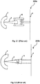
- Figure 2.1 and figure 2.2 depicts the two fixing model for the satellites 6.
- One is to leave some runner of plastic mould 9 and fixing them with a spring supported jaw 10 (type-1) or screwing them with spring screw (type-2) and nut connector 11 holes as shown in Figure 2.1 and figure 2.2 .
- spring supported jaw fixing method the runner of plastic mould 9 parts are projected out from the moulding tools and that leads to coat unwanted parts because of fixing.
- Other problems in spring supported Jaw 10 and fixing screw along with nut connector 11 is the fixtures may also stay in effective magnetic area 4 and that also can be coated as shown in Figure 1.1 and Figure 1.2 .
- the spring may get blocked and the jaw 10 that is supported by the spring 10 may get stuck. Further, the jaw cannot press on to the parts/ substrates. Consequently, the jaw and the spring need to be changed or cleaned.
- the fixing process itself may consume more time. Further, the fixing method requires skilled labor and that leads to increase in labor cost.
- the performance of PVD vacuum coatings system is determined based on adjustment mechanism for rotating/turning a substrate that needs to be coated and the substrate fixing time. Further, the performance of the PVD is determined by flexibility of the system to coat different structured / shaped parts that need to be coated. To solve these problems there exist a need to develop a flexible fixing system without a need for cleaning requirement in PVD satellites (6).
- the prior art US5334302A is related to a magnetron sputtering apparatus and sputtering gun for use in the same.
- the prior art includes a vacuum chamber, multiple spray guns for spraying the coating material in plasma form, building support pieces, target surfaces that needs to be coated with the coating material, cooling blocks, a magnetron atomizer and so on. Further, the target surfaces are connected to the cooling blocks by means of a clamp bracket and said clamp bracket is mounted to the cooling block by means of pins. Further the prior art discloses a mounting device comprising a pin and a clamp for mounting on a cooling block which serves as a satellite part of a target surface used as a substrate for use in magnetron spraying systems. But the prior art does not contain features for compressing base sheet parts with different squeeze grades.
- a rotating cathode for use in magnetron sputtering systems includes a method and apparatus for mounting a target on a flange-supported shaft.
- Said apparatus assists in the application of higher torque to the target by accelerating the installation of the target in the system, reducing the heat loss between the shaft and the target, and equalizing the pressure distribution applied during coupling of the shaft and the target.
- Said mounting bracket consists of angular rings and discrete clamp arms. Said discrete clamp arms are concentric with the target and are angularly rotatable.
- the patent document WO02070777A1 discloses a mounting arrangement for use in magnetron sputtering systems, which is used for connecting the rotary shaft of the target material and includes clamp pieces which rotate coaxially with the target.
- said mounting apparatus is capable of performing at least two circular axial turning motions and operating at different power ratings, It does not contain any explanation as to whether the substrate parts can be compressed.
- Prior art US5800687A discloses a coating system for coating CD-like flat materials.
- the system comprises a spray catheter; a mask used to cover only the exposed portions of the underlying layer to be coated thereon; the inner and outer guide elements providing the rotational movement of said mantle and two circular flanges.
- the two circular flanges provided in the closed system at the vacuum environment are connected with two clamp pieces as two axles.
- the patent document US5800687A does not provide any explanation as to the ability to carry out at least two circular axial rotational movements and to work with different strength grades so that the substrate parts having different hardness grades can be compacted.
- the subject-matter of the prior arts described so far does not have the capability to perform at least two circular axial turning motions and to work with different strength/ squeeze grades so that the substrate/ parts having different hardness grades can be compressed.
- the before mentioned object is solved by a tool for fixing a substrate with a satellite in a PVD process according to claim 1.
- the tool for fixing a substrate with a satellite in a PVD process according to the present invention can include a clamp, at least two connecting means and a forcing structure.
- the clamp can include at least two connection pins and a head.
- the two connecting means can be provided with two or more non-coaxial axis holes.
- the forcing structure can be provided to control a squeeze force on the substrate.
- the clamp head can be provided to hold the substrate.
- the connection pins of the clamp can be fixed in said non-coaxial axis holes thereby making squeeze force on the substrate for coating.
- One end of the forcing structure can be connected to the connecting means and another end may be connected to the satellite.
- the forcing structure can enable the substrate to rotate in two circular axial turning motions. Further, the tool can work with different strength/ squeeze grades for getting better efficiency. That is better coating over the substrate material.
- the squeezing force direction or tension of the squeezing of the substrate can be calculated using distance between two or more non-coaxial axis's holes.
- the two or more non-coaxial axis's holes may aid to fix different parts with different squeeze level.
- the tool can be capable to work in different force levels by setting the forcing structure at different force levels. Further, the tool is capable to use for any part of the substrate.
- the part of the substrate includes circular, rectangular, triangular or any uneven part.
- the forcing structure is capable to use with different head clamp.
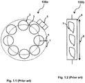
- Fig. 1.1 illustrates the top view 100a of the vacuum chamber 1 of the PVD processing unit according to the prior art.
- the vacuum chamber 1 utilizes two orbit rotations that are satellite 6 first turning orbit 2 and satellite 6 second turning orbit 3 to obtain higher coating efficiency.
- the satellite 6 second turning orbit 3 makes the substrate 7 to move near a target 5 that is the coating material.
- the effective area of coating region 4 is less compared to the exposed substrate 7.
- Fig. 1.2 illustrates the position 100b of the substrate and satellite the PVD processing unit according to the prior art.
- the substrate 7 materials are placed over the satellite 6 to perform coating process using PVD.
- the effective coating height 8 of the PVD can be decided based on the satellite.
- FIG. 2.1 and Fig. 2.2 illustrates the side view of conventional fixture tool of type-1 200a and type-2 respectively 200b for fixing substrate 7 in the PVD processing unit according to the prior art.
- the two fixing model for fixing the substrate 7 over the satellites 6 is depicted in figure 2.1 and figure 2.2.
- Figure 2.1 illustrates the satellite 2 that has a runner of plastic mould 9. The runner of plastic mould 9 is supported jaw 10 (type-1).
- Figure 2.2 illustrates the runner of plastic mould 9 is fixed by screwing them with spring screw (type-2) and nut connector 11 holes.
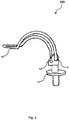
- Fig. 3 illustrates the tool 300 for fixing substrates 7 in a PVD processing unit according to an embodiment of the present invention.
- the tool for fixing a substrate 7 with a satellite 6 in a PVD process according to the present invention can include a clamp 16, at least two connecting means and a forcing structure 17.
- the clamp 16 can include at least two connection pins and a head.
- the two connecting means can be provided with two or more non-coaxial axis holes 12, 13 & 14 (shown in figure 4 ).
- the forcing structure 17 can be provided to control a squeeze force on the substrate 6.
- the clamp 16 head can be provided to hold the substrate 7.
- the connection pins of the clamp 16 can be fixed in the non-coaxial axis holes 12 & 13 thereby making squeeze force on the substrate 7 for coating.
- the forcing structure 17 can be connected to the connecting means and another end may be connected to the satellite 6.
- the tool can be used for fixing plastic substrates 7 for coating. Performance or usage of this tool may not affect the coating and also solve the problem of time consumption.
- the forcing structure 17 is capable to use with different clamp 16 head. Hence, the tool can be capable to use for any part of the substrate 7.
- the part of the substrate 7 includes circular, rectangular, triangular or any uneven part.
- the substrate material may include but is not limited to polymeric material and so on.
- Fig. 4 illustrates the possible position of connection pins 400 in the non-coaxial axis holes of the tool, according to the embodiment of the present invention.
- the possible position of the connection pins of the clamp 16 that can be fixed in the non-coaxial axis holes 12, 13 & 14 of the tool is illustrated for three non-coaxial axis holes 12, 13 & 14 in the connecting means. Either any two of the three non-coaxial axis holes 12, 13 & 14 can be connected to obtain the squeezing force.
- the squeezing force direction 15 or tension of the squeezing of the substrate can be calculated using distance between two or more non-coaxial axis's holes.
- the two or more non-coaxial axis's holes 12, 13 & 14 may aid to fix different parts with different squeeze level.
- the tool can be capable to work in different force levels by setting the forcing structure 17 at different force levels.
- one squeezing tool or tool can work for different part (substrate) shapes. Further, the need for different satellites 6 for adjusting the squeezing force can be eliminated by the tool. The rough design of tool may not affect the PVD coating. In addition to that, the lesser process cycle time for loading and unloading of parts reduces the overall coating process time.
- the present invention refers to a tool for fixing a substrate with a satellite in a PVD process.
- the tool for fixing the substrate 7 with the satellite 6 in a PVD process to perform at least two circular axial turning motions and to work with different strength/ squeeze grades for getting better coating efficiency.
- the tool preferably comprises of a clamp 16, at least two connecting means and a forcing structure 17.
- the clamp 16 may include at least two connection pins and a head.
- the forcing structure 17 can be provided to control a squeeze force on the substrate 7.
- the connection pins of the clamp 16 can be fixed in non-coaxial axis holes 12, 13 that may be provided in the connecting means thereby making squeeze force on the substrate 7 for coating.
- One end of the forcing structure 17 can be connected to the connecting means and another end may be connected to the satellite 6.
Landscapes
- Chemical & Material Sciences (AREA)
- Engineering & Computer Science (AREA)
- Mechanical Engineering (AREA)
- Chemical Kinetics & Catalysis (AREA)
- Materials Engineering (AREA)
- Metallurgy (AREA)
- Organic Chemistry (AREA)
- Physical Vapour Deposition (AREA)
Abstract
Description
- This invention refers to a tool for fixing a substrate with a satellite in PVD (Physical Vapor Deposition) processing unit according to
claim 1. - Generally PVD (Physical vapor deposition) system is utilized for depositing a thin layer of coating over a predefined surface/ substrate at an inert atmosphere. A target material is selected based on the required coating over the substrate. Different types of PVD systems are available and in that magnetron sputtering system is one type of PVD. The magnetron sputtering is used to deposit thin films of plastics over the substrate. Further, the process is carried out in a vacuum or low-pressure environment. A magnetic field is used to concentrate high-energy ions onto the coating target in order to leave the atoms. Magnetron sputtering is a powerful, flexible and material-independent coating process, which can be used to coat most of common surfaces with a variety of materials. The high-energy atoms can penetrate into the substrate to create uniform and tight patterns that improve durability and performance of surface of the substrate.
- The magnetron sputtering system utilizes electrical energy to create high-energy plasma ions in a vacuum. Further, the magnetron provides a magnetic field that concentrates the ions onto the target (cathode). As the ions strike the target, neutral atoms, molecules and secondary electrons are emitted (sputtering). The ejected atoms move toward the substrate and they get condensed to form a thin film of the coating material. The secondary electrons may collide with the inert gas in the chamber and can help to maintain the plasma. The plasma, in the conventional magnetron sputtering method, is concentrated above the target and might cause ions to bombard and affect the corresponding film on the substrate.
- Conversely, this is eliminated in the unbalanced magnetron sputtering method; hence the magnetic field is arranged in a way to spread the plasma. This helps to maintain a low ion concentration near the substrate. In the apparatus, effective area parts (substrate parts under the magnetic field) are assembled on to a fixture called as satellite. Usually, the satellite is designed with respect to dimension and the shape of parts/ substrate that needs to be coated.
- Some difficulties occurred while fixing the substrate on to the satellite / fixture for coating. Hence, the substrate/ part may rotate inside the vacuum room in a high speed as depicted in
Figure 1.1 and figure 1.2 . Further, many of the systems are using two orbit rotations that are satellite first turningorbit 2 and satellite second turningorbit 3 to obtain higher coating efficiency.Figure 2.1 and figure 2.2 depicts the two fixing model for thesatellites 6. One is to leave some runner ofplastic mould 9 and fixing them with a spring supported jaw 10 (type-1) or screwing them with spring screw (type-2) andnut connector 11 holes as shown inFigure 2.1 and figure 2.2 . - In spring supported jaw fixing method, the runner of
plastic mould 9 parts are projected out from the moulding tools and that leads to coat unwanted parts because of fixing. Other problems in spring supported Jaw 10 and fixing screw along withnut connector 11 is the fixtures may also stay in effective magnetic area 4 and that also can be coated as shown inFigure 1.1 and Figure 1.2 . In some processing cycles, the spring may get blocked and thejaw 10 that is supported by thespring 10 may get stuck. Further, the jaw cannot press on to the parts/ substrates. Consequently, the jaw and the spring need to be changed or cleaned. In another method of fixing substrate on to the satellite using the fixing screw andnut connector 11, the fixing process itself may consume more time. Further, the fixing method requires skilled labor and that leads to increase in labor cost. Usually the performance of PVD vacuum coatings system is determined based on adjustment mechanism for rotating/turning a substrate that needs to be coated and the substrate fixing time. Further, the performance of the PVD is determined by flexibility of the system to coat different structured / shaped parts that need to be coated. To solve these problems there exist a need to develop a flexible fixing system without a need for cleaning requirement in PVD satellites (6). - The prior art
US5334302A is related to a magnetron sputtering apparatus and sputtering gun for use in the same. The prior art includes a vacuum chamber, multiple spray guns for spraying the coating material in plasma form, building support pieces, target surfaces that needs to be coated with the coating material, cooling blocks, a magnetron atomizer and so on. Further, the target surfaces are connected to the cooling blocks by means of a clamp bracket and said clamp bracket is mounted to the cooling block by means of pins. Further the prior art discloses a mounting device comprising a pin and a clamp for mounting on a cooling block which serves as a satellite part of a target surface used as a substrate for use in magnetron spraying systems. But the prior art does not contain features for compressing base sheet parts with different squeeze grades. - In another prior art
WO02070777A1 WO02070777A1 - Prior art
US5800687A discloses a coating system for coating CD-like flat materials. The system comprises a spray catheter; a mask used to cover only the exposed portions of the underlying layer to be coated thereon; the inner and outer guide elements providing the rotational movement of said mantle and two circular flanges. The two circular flanges provided in the closed system at the vacuum environment are connected with two clamp pieces as two axles. The patent documentUS5800687A does not provide any explanation as to the ability to carry out at least two circular axial rotational movements and to work with different strength grades so that the substrate parts having different hardness grades can be compacted. - The subject-matter of the prior arts described so far does not have the capability to perform at least two circular axial turning motions and to work with different strength/ squeeze grades so that the substrate/ parts having different hardness grades can be compressed.
- It is therefore the object of the present invention to provide a device, in particular a tool for fixing substares in a PVD process to perform at least two circular axial turning motions and to work with different strength/ squeeze grades for getting better efficiency compared to the known devices.
- The before mentioned object is solved by a tool for fixing a substrate with a satellite in a PVD process according to
claim 1. The tool for fixing a substrate with a satellite in a PVD process according to the present invention can include a clamp, at least two connecting means and a forcing structure. The clamp can include at least two connection pins and a head. The two connecting means can be provided with two or more non-coaxial axis holes. The forcing structure can be provided to control a squeeze force on the substrate. The clamp head can be provided to hold the substrate. The connection pins of the clamp can be fixed in said non-coaxial axis holes thereby making squeeze force on the substrate for coating. One end of the forcing structure can be connected to the connecting means and another end may be connected to the satellite. - This solution is beneficial since the forcing structure can enable the substrate to rotate in two circular axial turning motions. Further, the tool can work with different strength/ squeeze grades for getting better efficiency. That is better coating over the substrate material.
- Further preferred embodiments are subject-matter of dependent claims and/or of the following specification parts.
- According to a preferred embodiment of the present invention, the squeezing force direction or tension of the squeezing of the substrate can be calculated using distance between two or more non-coaxial axis's holes. The two or more non-coaxial axis's holes may aid to fix different parts with different squeeze level. The tool can be capable to work in different force levels by setting the forcing structure at different force levels. Further, the tool is capable to use for any part of the substrate. The part of the substrate includes circular, rectangular, triangular or any uneven part. The forcing structure is capable to use with different head clamp.
- Further benefits, goals and features of the present invention will be described by the following specification of the attached figures, in which components of the invention are exemplarily illustrated. Components of the devices and method according to the inventions, which match at least essentially with respect to their function can be marked with the same reference sign, wherein such components do not have to be marked or described in all figures.
- The invention is just exemplarily described with respect to the attached figures in the following.
-
- Fig. 1.1
- illustrates the top view of the vacuum chamber of the PVD processing unit according to the prior art;
- Fig. 1.2
- illustrates the position of the substrate and satellite the PVD processing unit according to the prior art;
- Fig. 2.1
- illustrates the side view of conventional fixture tool of type-1 for fixing substrate in the PVD processing unit according to the prior art;
- Fig. 2.2
- illustrates the side view of conventional fixture tool of type-2 for fixing substrate in the PVD processing unit according to the prior art;
- Fig. 3
- illustrates the tool for fixing substrate in a PVD processing unit according to an embodiment of the present invention; and
- Fig. 4
- illustrates the possible position of connection pins in the non-coaxial axis holes of the tool, according to the embodiment of the present invention.
-
Fig. 1.1 illustrates thetop view 100a of thevacuum chamber 1 of the PVD processing unit according to the prior art. According to the prior art, Thevacuum chamber 1 utilizes two orbit rotations that aresatellite 6first turning orbit 2 andsatellite 6second turning orbit 3 to obtain higher coating efficiency. Thesatellite 6second turning orbit 3 makes thesubstrate 7 to move near atarget 5 that is the coating material. The effective area of coating region 4 is less compared to the exposedsubstrate 7. -
Fig. 1.2 illustrates theposition 100b of the substrate and satellite the PVD processing unit according to the prior art. Thesubstrate 7 materials are placed over thesatellite 6 to perform coating process using PVD. Theeffective coating height 8 of the PVD can be decided based on the satellite. -
Fig. 2.1 and Fig. 2.2 illustrates the side view of conventional fixture tool of type-1 200a and type-2 respectively 200b for fixingsubstrate 7 in the PVD processing unit according to the prior art. The two fixing model for fixing thesubstrate 7 over thesatellites 6 is depicted infigure 2.1 and figure 2.2. Figure 2.1 illustrates thesatellite 2 that has a runner ofplastic mould 9. The runner ofplastic mould 9 is supported jaw 10 (type-1).Figure 2.2 illustrates the runner ofplastic mould 9 is fixed by screwing them with spring screw (type-2) andnut connector 11 holes. -
Fig. 3 illustrates thetool 300 for fixingsubstrates 7 in a PVD processing unit according to an embodiment of the present invention. The tool for fixing asubstrate 7 with asatellite 6 in a PVD process according to the present invention can include aclamp 16, at least two connecting means and a forcingstructure 17. Theclamp 16 can include at least two connection pins and a head. The two connecting means can be provided with two or more non-coaxial axis holes 12, 13 & 14 (shown infigure 4 ). The forcingstructure 17 can be provided to control a squeeze force on thesubstrate 6. Theclamp 16 head can be provided to hold thesubstrate 7. The connection pins of theclamp 16 can be fixed in the non-coaxial axis holes 12 & 13 thereby making squeeze force on thesubstrate 7 for coating. One end of the forcingstructure 17 can be connected to the connecting means and another end may be connected to thesatellite 6. The tool can be used for fixingplastic substrates 7 for coating. Performance or usage of this tool may not affect the coating and also solve the problem of time consumption. The forcingstructure 17 is capable to use withdifferent clamp 16 head. Hence, the tool can be capable to use for any part of thesubstrate 7. The part of thesubstrate 7 includes circular, rectangular, triangular or any uneven part. The substrate material may include but is not limited to polymeric material and so on. -
Fig. 4 illustrates the possible position of connection pins 400 in the non-coaxial axis holes of the tool, according to the embodiment of the present invention. The possible position of the connection pins of theclamp 16 that can be fixed in the non-coaxial axis holes 12, 13 & 14 of the tool is illustrated for three non-coaxial axis holes 12, 13 & 14 in the connecting means. Either any two of the three non-coaxial axis holes 12, 13 & 14 can be connected to obtain the squeezing force. The squeezingforce direction 15 or tension of the squeezing of the substrate can be calculated using distance between two or more non-coaxial axis's holes. - The two or more non-coaxial axis's
holes structure 17 at different force levels. - According to a preferred embodiment of the present invention, one squeezing tool or tool can work for different part (substrate) shapes. Further, the need for
different satellites 6 for adjusting the squeezing force can be eliminated by the tool. The rough design of tool may not affect the PVD coating. In addition to that, the lesser process cycle time for loading and unloading of parts reduces the overall coating process time. - Thus, the present invention refers to a tool for fixing a substrate with a satellite in a PVD process. The tool for fixing the
substrate 7 with thesatellite 6 in a PVD process to perform at least two circular axial turning motions and to work with different strength/ squeeze grades for getting better coating efficiency. The tool preferably comprises of aclamp 16, at least two connecting means and a forcingstructure 17. Theclamp 16 may include at least two connection pins and a head. The forcingstructure 17 can be provided to control a squeeze force on thesubstrate 7. The connection pins of theclamp 16 can be fixed in non-coaxial axis holes 12, 13 that may be provided in the connecting means thereby making squeeze force on thesubstrate 7 for coating. One end of the forcingstructure 17 can be connected to the connecting means and another end may be connected to thesatellite 6. -
- 1
- vacuum chamber of PVD
- 2
- satellite first turning orbit
- 3
- satellite second turning orbit
- 4
- effective coating region
- 5
- target (coating material) of the magnetron sputtering unit (or PVD)
- 6
- satellite
- 7
- substrate for coating
- 8
- effective coating height
- 9
- runner of plastic mold
- 10
- spring supported jaw
- 11
- fixing screw and nut connector
- 12
- non-coaxial first axis hole
- 13
- non-coaxial second axis hole
- 14
- non-coaxial third axis hole
- 15
- squeeze forcing direction
- 16
- non-coaxial clamp
- 17
- forcing structure
- 100a
- top view of vacuum chamber
- 100b
- the position of the substrate and satellite
- 200a
- side view of conventional fixture tool of type-1
- 200b
- side view of conventional fixture tool of type-2
- 300
- tool for fixing substrates in a PVD processing unit
- 400
- possible position of connection pins in the non-coaxial axis holes of the tool
Claims (7)
- A tool for fixing a substrate (7) with a satellite (6) in a PVD process comprises of,
a clamp (16) with at least two connection pins and a head;
at least two connecting means provided with two or more non-coaxial axis holes (12,13);
a forcing structure (17) provided to control a squeeze force on the substrate (7); wherein the clamp (16) head provided to hold the substrate (7);
wherein the connection pins of the clamp (16) is fixed in said non-coaxial axis holes (12,13) thereby making squeeze force on the substrate (7) for coating; and
wherein one end of the forcing structure (17) is connected to the connecting means and another end is connected to the satellite (6). - The tool of claim 1, wherein squeezing force direction (15) or tension of the squeezing of the substrate can be calculated using distance between two or more non-coaxial axis's holes (12,13).
- The tool of claim 1, wherein the two or more non-coaxial axis's holes (12, 13) help to fix different parts with different squeeze level.
- The tool of claim 1, wherein the tool capable to work in different force levels by setting the forcing structure (17) at different force levels.
- The tool of claim 1, wherein the tool capable to use for any part of the substrate (7).
- The tool of claim 5, wherein the part of the substrate (7) includes circular, rectangular, triangular or any uneven part.
- The tool of claim 1, wherein the forcing structure (17) is capable to use with different head clamp (16).
Priority Applications (1)
| Application Number | Priority Date | Filing Date | Title |
|---|---|---|---|
| EP17167150.6A EP3392371B1 (en) | 2017-04-19 | 2017-04-19 | A tool for fixing substrates in a pvd process |
Applications Claiming Priority (1)
| Application Number | Priority Date | Filing Date | Title |
|---|---|---|---|
| EP17167150.6A EP3392371B1 (en) | 2017-04-19 | 2017-04-19 | A tool for fixing substrates in a pvd process |
Publications (2)
| Publication Number | Publication Date |
|---|---|
| EP3392371A1 true EP3392371A1 (en) | 2018-10-24 |
| EP3392371B1 EP3392371B1 (en) | 2021-11-03 |
Family
ID=58701384
Family Applications (1)
| Application Number | Title | Priority Date | Filing Date |
|---|---|---|---|
| EP17167150.6A Active EP3392371B1 (en) | 2017-04-19 | 2017-04-19 | A tool for fixing substrates in a pvd process |
Country Status (1)
| Country | Link |
|---|---|
| EP (1) | EP3392371B1 (en) |
Citations (7)
| Publication number | Priority date | Publication date | Assignee | Title |
|---|---|---|---|---|
| US5168168A (en) * | 1991-05-10 | 1992-12-01 | New Focus, Inc. | Device for centering round articles |
| DE4232902A1 (en) * | 1992-09-30 | 1994-03-31 | Leybold Ag | Substrate holder - has two pairs of elastic holding fingers located in the substrate plane |
| US5325812A (en) * | 1991-12-19 | 1994-07-05 | Balzers Aktiengesellschaft | Substrate holding and rotating arrangement for vacuum processes |
| US5334302A (en) | 1991-11-15 | 1994-08-02 | Tokyo Electron Limited | Magnetron sputtering apparatus and sputtering gun for use in the same |
| US5800687A (en) | 1996-04-13 | 1998-09-01 | Singulus Technologies Gmbh | Device for masking or covering substrates |
| EP1054439A1 (en) * | 1999-05-15 | 2000-11-22 | Applied Materials, Inc. | Gripper for supporting substrate in a vertical orientation |
| WO2002070777A1 (en) | 2001-02-17 | 2002-09-12 | David Mark Lynn | Cylindrical magnetron target and apparatus for affixing the target to a rotatable spindle assembly |
-
2017
- 2017-04-19 EP EP17167150.6A patent/EP3392371B1/en active Active
Patent Citations (7)
| Publication number | Priority date | Publication date | Assignee | Title |
|---|---|---|---|---|
| US5168168A (en) * | 1991-05-10 | 1992-12-01 | New Focus, Inc. | Device for centering round articles |
| US5334302A (en) | 1991-11-15 | 1994-08-02 | Tokyo Electron Limited | Magnetron sputtering apparatus and sputtering gun for use in the same |
| US5325812A (en) * | 1991-12-19 | 1994-07-05 | Balzers Aktiengesellschaft | Substrate holding and rotating arrangement for vacuum processes |
| DE4232902A1 (en) * | 1992-09-30 | 1994-03-31 | Leybold Ag | Substrate holder - has two pairs of elastic holding fingers located in the substrate plane |
| US5800687A (en) | 1996-04-13 | 1998-09-01 | Singulus Technologies Gmbh | Device for masking or covering substrates |
| EP1054439A1 (en) * | 1999-05-15 | 2000-11-22 | Applied Materials, Inc. | Gripper for supporting substrate in a vertical orientation |
| WO2002070777A1 (en) | 2001-02-17 | 2002-09-12 | David Mark Lynn | Cylindrical magnetron target and apparatus for affixing the target to a rotatable spindle assembly |
Also Published As
| Publication number | Publication date |
|---|---|
| EP3392371B1 (en) | 2021-11-03 |
Similar Documents
| Publication | Publication Date | Title |
|---|---|---|
| US5795451A (en) | Sputtering apparatus with a rotating magnet array | |
| KR100692584B1 (en) | Coating device with large area assembly of rotatable magnetron | |
| KR100559285B1 (en) | Apparatus for steering the arc in a cathodic arc coater | |
| AU2012367305B2 (en) | Thermo spray gun with removable nozzle tip and method making and using the same | |
| US8241473B2 (en) | Sputter-coating apparatus | |
| JP6438657B2 (en) | Cylindrical deposition source | |
| WO1999022396A3 (en) | Enhanced macroparticle filter and cathode arc source | |
| US8500977B2 (en) | Coating apparatus | |
| CN105887036B (en) | A kind of workpiece fixture | |
| US20150332900A1 (en) | Method and table assembly for applying coatings to spherical components | |
| TW200712233A (en) | Coating machine and method for operating a coating machine | |
| WO1992020831A1 (en) | Improved quick change sputter target assembly | |
| EP3392371B1 (en) | A tool for fixing substrates in a pvd process | |
| CN113227446B (en) | Sputtering apparatus and sputtering method | |
| JP2022532148A (en) | Movable workpiece carrier device for holding the workpiece to be processed | |
| KR100530545B1 (en) | Apparatus for driving the arc in a cathodic arc coater | |
| CN100540726C (en) | Modular units for coated surfaces | |
| JP3336421B2 (en) | Sputtering equipment | |
| CN219824347U (en) | Angle adjusting device and corresponding physical vapor deposition device | |
| RU2095467C1 (en) | Multiple-beam installation for ion-plasma treatment of part surfaces | |
| CN211227319U (en) | Steel ball plasma coating clamp | |
| CN214496456U (en) | Double-beam excitation type metal-gas ionization equipment | |
| WO2019208551A1 (en) | Film deposition device and film deposition method | |
| CN222476730U (en) | Ion beam sputtering coating equipment | |
| CN210458360U (en) | Gas distribution structure |
Legal Events
| Date | Code | Title | Description |
|---|---|---|---|
| PUAI | Public reference made under article 153(3) epc to a published international application that has entered the european phase |
Free format text: ORIGINAL CODE: 0009012 |
|
| STAA | Information on the status of an ep patent application or granted ep patent |
Free format text: STATUS: THE APPLICATION HAS BEEN PUBLISHED |
|
| AK | Designated contracting states |
Kind code of ref document: A1 Designated state(s): AL AT BE BG CH CY CZ DE DK EE ES FI FR GB GR HR HU IE IS IT LI LT LU LV MC MK MT NL NO PL PT RO RS SE SI SK SM TR |
|
| AX | Request for extension of the european patent |
Extension state: BA ME |
|
| STAA | Information on the status of an ep patent application or granted ep patent |
Free format text: STATUS: REQUEST FOR EXAMINATION WAS MADE |
|
| 17P | Request for examination filed |
Effective date: 20190404 |
|
| RBV | Designated contracting states (corrected) |
Designated state(s): AL AT BE BG CH CY CZ DE DK EE ES FI FR GB GR HR HU IE IS IT LI LT LU LV MC MK MT NL NO PL PT RO RS SE SI SK SM TR |
|
| GRAP | Despatch of communication of intention to grant a patent |
Free format text: ORIGINAL CODE: EPIDOSNIGR1 |
|
| STAA | Information on the status of an ep patent application or granted ep patent |
Free format text: STATUS: GRANT OF PATENT IS INTENDED |
|
| INTG | Intention to grant announced |
Effective date: 20210520 |
|
| GRAS | Grant fee paid |
Free format text: ORIGINAL CODE: EPIDOSNIGR3 |
|
| GRAA | (expected) grant |
Free format text: ORIGINAL CODE: 0009210 |
|
| STAA | Information on the status of an ep patent application or granted ep patent |
Free format text: STATUS: THE PATENT HAS BEEN GRANTED |
|
| AK | Designated contracting states |
Kind code of ref document: B1 Designated state(s): AL AT BE BG CH CY CZ DE DK EE ES FI FR GB GR HR HU IE IS IT LI LT LU LV MC MK MT NL NO PL PT RO RS SE SI SK SM TR |
|
| REG | Reference to a national code |
Ref country code: GB Ref legal event code: FG4D |
|
| REG | Reference to a national code |
Ref country code: AT Ref legal event code: REF Ref document number: 1444011 Country of ref document: AT Kind code of ref document: T Effective date: 20211115 Ref country code: CH Ref legal event code: EP |
|
| REG | Reference to a national code |
Ref country code: DE Ref legal event code: R096 Ref document number: 602017048583 Country of ref document: DE |
|
| REG | Reference to a national code |
Ref country code: IE Ref legal event code: FG4D |
|
| REG | Reference to a national code |
Ref country code: LT Ref legal event code: MG9D |
|
| REG | Reference to a national code |
Ref country code: NL Ref legal event code: MP Effective date: 20211103 |
|
| REG | Reference to a national code |
Ref country code: AT Ref legal event code: MK05 Ref document number: 1444011 Country of ref document: AT Kind code of ref document: T Effective date: 20211103 |
|
| PG25 | Lapsed in a contracting state [announced via postgrant information from national office to epo] |
Ref country code: RS Free format text: LAPSE BECAUSE OF FAILURE TO SUBMIT A TRANSLATION OF THE DESCRIPTION OR TO PAY THE FEE WITHIN THE PRESCRIBED TIME-LIMIT Effective date: 20211103 Ref country code: LT Free format text: LAPSE BECAUSE OF FAILURE TO SUBMIT A TRANSLATION OF THE DESCRIPTION OR TO PAY THE FEE WITHIN THE PRESCRIBED TIME-LIMIT Effective date: 20211103 Ref country code: FI Free format text: LAPSE BECAUSE OF FAILURE TO SUBMIT A TRANSLATION OF THE DESCRIPTION OR TO PAY THE FEE WITHIN THE PRESCRIBED TIME-LIMIT Effective date: 20211103 Ref country code: BG Free format text: LAPSE BECAUSE OF FAILURE TO SUBMIT A TRANSLATION OF THE DESCRIPTION OR TO PAY THE FEE WITHIN THE PRESCRIBED TIME-LIMIT Effective date: 20220203 Ref country code: AT Free format text: LAPSE BECAUSE OF FAILURE TO SUBMIT A TRANSLATION OF THE DESCRIPTION OR TO PAY THE FEE WITHIN THE PRESCRIBED TIME-LIMIT Effective date: 20211103 |
|
| PG25 | Lapsed in a contracting state [announced via postgrant information from national office to epo] |
Ref country code: IS Free format text: LAPSE BECAUSE OF FAILURE TO SUBMIT A TRANSLATION OF THE DESCRIPTION OR TO PAY THE FEE WITHIN THE PRESCRIBED TIME-LIMIT Effective date: 20220303 Ref country code: SE Free format text: LAPSE BECAUSE OF FAILURE TO SUBMIT A TRANSLATION OF THE DESCRIPTION OR TO PAY THE FEE WITHIN THE PRESCRIBED TIME-LIMIT Effective date: 20211103 Ref country code: PT Free format text: LAPSE BECAUSE OF FAILURE TO SUBMIT A TRANSLATION OF THE DESCRIPTION OR TO PAY THE FEE WITHIN THE PRESCRIBED TIME-LIMIT Effective date: 20220303 Ref country code: PL Free format text: LAPSE BECAUSE OF FAILURE TO SUBMIT A TRANSLATION OF THE DESCRIPTION OR TO PAY THE FEE WITHIN THE PRESCRIBED TIME-LIMIT Effective date: 20211103 Ref country code: NO Free format text: LAPSE BECAUSE OF FAILURE TO SUBMIT A TRANSLATION OF THE DESCRIPTION OR TO PAY THE FEE WITHIN THE PRESCRIBED TIME-LIMIT Effective date: 20220203 Ref country code: NL Free format text: LAPSE BECAUSE OF FAILURE TO SUBMIT A TRANSLATION OF THE DESCRIPTION OR TO PAY THE FEE WITHIN THE PRESCRIBED TIME-LIMIT Effective date: 20211103 Ref country code: LV Free format text: LAPSE BECAUSE OF FAILURE TO SUBMIT A TRANSLATION OF THE DESCRIPTION OR TO PAY THE FEE WITHIN THE PRESCRIBED TIME-LIMIT Effective date: 20211103 Ref country code: HR Free format text: LAPSE BECAUSE OF FAILURE TO SUBMIT A TRANSLATION OF THE DESCRIPTION OR TO PAY THE FEE WITHIN THE PRESCRIBED TIME-LIMIT Effective date: 20211103 Ref country code: GR Free format text: LAPSE BECAUSE OF FAILURE TO SUBMIT A TRANSLATION OF THE DESCRIPTION OR TO PAY THE FEE WITHIN THE PRESCRIBED TIME-LIMIT Effective date: 20220204 Ref country code: ES Free format text: LAPSE BECAUSE OF FAILURE TO SUBMIT A TRANSLATION OF THE DESCRIPTION OR TO PAY THE FEE WITHIN THE PRESCRIBED TIME-LIMIT Effective date: 20211103 |
|
| PG25 | Lapsed in a contracting state [announced via postgrant information from national office to epo] |
Ref country code: SM Free format text: LAPSE BECAUSE OF FAILURE TO SUBMIT A TRANSLATION OF THE DESCRIPTION OR TO PAY THE FEE WITHIN THE PRESCRIBED TIME-LIMIT Effective date: 20211103 Ref country code: SK Free format text: LAPSE BECAUSE OF FAILURE TO SUBMIT A TRANSLATION OF THE DESCRIPTION OR TO PAY THE FEE WITHIN THE PRESCRIBED TIME-LIMIT Effective date: 20211103 Ref country code: RO Free format text: LAPSE BECAUSE OF FAILURE TO SUBMIT A TRANSLATION OF THE DESCRIPTION OR TO PAY THE FEE WITHIN THE PRESCRIBED TIME-LIMIT Effective date: 20211103 Ref country code: EE Free format text: LAPSE BECAUSE OF FAILURE TO SUBMIT A TRANSLATION OF THE DESCRIPTION OR TO PAY THE FEE WITHIN THE PRESCRIBED TIME-LIMIT Effective date: 20211103 Ref country code: DK Free format text: LAPSE BECAUSE OF FAILURE TO SUBMIT A TRANSLATION OF THE DESCRIPTION OR TO PAY THE FEE WITHIN THE PRESCRIBED TIME-LIMIT Effective date: 20211103 Ref country code: CZ Free format text: LAPSE BECAUSE OF FAILURE TO SUBMIT A TRANSLATION OF THE DESCRIPTION OR TO PAY THE FEE WITHIN THE PRESCRIBED TIME-LIMIT Effective date: 20211103 |
|
| REG | Reference to a national code |
Ref country code: DE Ref legal event code: R097 Ref document number: 602017048583 Country of ref document: DE |
|
| PLBE | No opposition filed within time limit |
Free format text: ORIGINAL CODE: 0009261 |
|
| STAA | Information on the status of an ep patent application or granted ep patent |
Free format text: STATUS: NO OPPOSITION FILED WITHIN TIME LIMIT |
|
| 26N | No opposition filed |
Effective date: 20220804 |
|
| PG25 | Lapsed in a contracting state [announced via postgrant information from national office to epo] |
Ref country code: AL Free format text: LAPSE BECAUSE OF FAILURE TO SUBMIT A TRANSLATION OF THE DESCRIPTION OR TO PAY THE FEE WITHIN THE PRESCRIBED TIME-LIMIT Effective date: 20211103 |
|
| PG25 | Lapsed in a contracting state [announced via postgrant information from national office to epo] |
Ref country code: SI Free format text: LAPSE BECAUSE OF FAILURE TO SUBMIT A TRANSLATION OF THE DESCRIPTION OR TO PAY THE FEE WITHIN THE PRESCRIBED TIME-LIMIT Effective date: 20211103 |
|
| REG | Reference to a national code |
Ref country code: CH Ref legal event code: PL |
|
| REG | Reference to a national code |
Ref country code: BE Ref legal event code: MM Effective date: 20220430 |
|
| PG25 | Lapsed in a contracting state [announced via postgrant information from national office to epo] |
Ref country code: MC Free format text: LAPSE BECAUSE OF FAILURE TO SUBMIT A TRANSLATION OF THE DESCRIPTION OR TO PAY THE FEE WITHIN THE PRESCRIBED TIME-LIMIT Effective date: 20211103 Ref country code: LU Free format text: LAPSE BECAUSE OF NON-PAYMENT OF DUE FEES Effective date: 20220419 Ref country code: LI Free format text: LAPSE BECAUSE OF NON-PAYMENT OF DUE FEES Effective date: 20220430 Ref country code: FR Free format text: LAPSE BECAUSE OF NON-PAYMENT OF DUE FEES Effective date: 20220430 Ref country code: CH Free format text: LAPSE BECAUSE OF NON-PAYMENT OF DUE FEES Effective date: 20220430 |
|
| PG25 | Lapsed in a contracting state [announced via postgrant information from national office to epo] |
Ref country code: BE Free format text: LAPSE BECAUSE OF NON-PAYMENT OF DUE FEES Effective date: 20220430 |
|
| PG25 | Lapsed in a contracting state [announced via postgrant information from national office to epo] |
Ref country code: IE Free format text: LAPSE BECAUSE OF NON-PAYMENT OF DUE FEES Effective date: 20220419 |
|
| PG25 | Lapsed in a contracting state [announced via postgrant information from national office to epo] |
Ref country code: IT Free format text: LAPSE BECAUSE OF FAILURE TO SUBMIT A TRANSLATION OF THE DESCRIPTION OR TO PAY THE FEE WITHIN THE PRESCRIBED TIME-LIMIT Effective date: 20211103 |
|
| PGFP | Annual fee paid to national office [announced via postgrant information from national office to epo] |
Ref country code: GB Payment date: 20230920 Year of fee payment: 7 |
|
| PGFP | Annual fee paid to national office [announced via postgrant information from national office to epo] |
Ref country code: DE Payment date: 20230920 Year of fee payment: 7 |
|
| PG25 | Lapsed in a contracting state [announced via postgrant information from national office to epo] |
Ref country code: HU Free format text: LAPSE BECAUSE OF FAILURE TO SUBMIT A TRANSLATION OF THE DESCRIPTION OR TO PAY THE FEE WITHIN THE PRESCRIBED TIME-LIMIT; INVALID AB INITIO Effective date: 20170419 |
|
| PG25 | Lapsed in a contracting state [announced via postgrant information from national office to epo] |
Ref country code: MK Free format text: LAPSE BECAUSE OF FAILURE TO SUBMIT A TRANSLATION OF THE DESCRIPTION OR TO PAY THE FEE WITHIN THE PRESCRIBED TIME-LIMIT Effective date: 20211103 Ref country code: CY Free format text: LAPSE BECAUSE OF FAILURE TO SUBMIT A TRANSLATION OF THE DESCRIPTION OR TO PAY THE FEE WITHIN THE PRESCRIBED TIME-LIMIT Effective date: 20211103 |
|
| PG25 | Lapsed in a contracting state [announced via postgrant information from national office to epo] |
Ref country code: MT Free format text: LAPSE BECAUSE OF FAILURE TO SUBMIT A TRANSLATION OF THE DESCRIPTION OR TO PAY THE FEE WITHIN THE PRESCRIBED TIME-LIMIT Effective date: 20211103 |
|
| REG | Reference to a national code |
Ref country code: DE Ref legal event code: R119 Ref document number: 602017048583 Country of ref document: DE |
|
| GBPC | Gb: european patent ceased through non-payment of renewal fee |
Effective date: 20240419 |
|
| PG25 | Lapsed in a contracting state [announced via postgrant information from national office to epo] |
Ref country code: DE Free format text: LAPSE BECAUSE OF NON-PAYMENT OF DUE FEES Effective date: 20241105 |
|
| PG25 | Lapsed in a contracting state [announced via postgrant information from national office to epo] |
Ref country code: GB Free format text: LAPSE BECAUSE OF NON-PAYMENT OF DUE FEES Effective date: 20240419 |
|
| PG25 | Lapsed in a contracting state [announced via postgrant information from national office to epo] |
Ref country code: GB Free format text: LAPSE BECAUSE OF NON-PAYMENT OF DUE FEES Effective date: 20240419 Ref country code: DE Free format text: LAPSE BECAUSE OF NON-PAYMENT OF DUE FEES Effective date: 20241105 |
|
| PGFP | Annual fee paid to national office [announced via postgrant information from national office to epo] |
Ref country code: TR Payment date: 20260415 Year of fee payment: 10 |