EP3392175B1 - Dispenser - Google Patents
Dispenser Download PDFInfo
- Publication number
- EP3392175B1 EP3392175B1 EP18164279.4A EP18164279A EP3392175B1 EP 3392175 B1 EP3392175 B1 EP 3392175B1 EP 18164279 A EP18164279 A EP 18164279A EP 3392175 B1 EP3392175 B1 EP 3392175B1
- Authority
- EP
- European Patent Office
- Prior art keywords
- strip
- external
- guide
- previous
- roller
- Prior art date
- Legal status (The legal status is an assumption and is not a legal conclusion. Google has not performed a legal analysis and makes no representation as to the accuracy of the status listed.)
- Active
Links
- 230000001154 acute effect Effects 0.000 claims description 5
- 230000008878 coupling Effects 0.000 claims description 4
- 238000010168 coupling process Methods 0.000 claims description 4
- 238000005859 coupling reaction Methods 0.000 claims description 4
- 239000004820 Pressure-sensitive adhesive Substances 0.000 claims 1
- 230000000452 restraining effect Effects 0.000 claims 1
- 239000000853 adhesive Substances 0.000 description 13
- 239000008188 pellet Substances 0.000 description 4
- 238000000926 separation method Methods 0.000 description 4
- 238000005266 casting Methods 0.000 description 1
- 239000003086 colorant Substances 0.000 description 1
- 238000000605 extraction Methods 0.000 description 1
- 238000012423 maintenance Methods 0.000 description 1
- 230000004048 modification Effects 0.000 description 1
- 238000012986 modification Methods 0.000 description 1
- 239000000126 substance Substances 0.000 description 1
Images

Classifications
-
- B—PERFORMING OPERATIONS; TRANSPORTING
- B65—CONVEYING; PACKING; STORING; HANDLING THIN OR FILAMENTARY MATERIAL
- B65H—HANDLING THIN OR FILAMENTARY MATERIAL, e.g. SHEETS, WEBS, CABLES
- B65H37/00—Article or web delivery apparatus incorporating devices for performing specified auxiliary operations
- B65H37/002—Web delivery apparatus, the web serving as support for articles, material or another web
- B65H37/005—Hand-held apparatus
- B65H37/007—Applicators for applying coatings, e.g. correction, colour or adhesive coatings
-
- B—PERFORMING OPERATIONS; TRANSPORTING
- B65—CONVEYING; PACKING; STORING; HANDLING THIN OR FILAMENTARY MATERIAL
- B65H—HANDLING THIN OR FILAMENTARY MATERIAL, e.g. SHEETS, WEBS, CABLES
- B65H35/00—Delivering articles from cutting or line-perforating machines; Article or web delivery apparatus incorporating cutting or line-perforating devices, e.g. adhesive tape dispensers
- B65H35/0006—Article or web delivery apparatus incorporating cutting or line-perforating devices
- B65H35/002—Hand-held or table apparatus
-
- B—PERFORMING OPERATIONS; TRANSPORTING
- B65—CONVEYING; PACKING; STORING; HANDLING THIN OR FILAMENTARY MATERIAL
- B65H—HANDLING THIN OR FILAMENTARY MATERIAL, e.g. SHEETS, WEBS, CABLES
- B65H35/00—Delivering articles from cutting or line-perforating machines; Article or web delivery apparatus incorporating cutting or line-perforating devices, e.g. adhesive tape dispensers
- B65H35/0006—Article or web delivery apparatus incorporating cutting or line-perforating devices
- B65H35/0073—Details
- B65H35/008—Arrangements or adaptations of cutting devices
-
- B—PERFORMING OPERATIONS; TRANSPORTING
- B65—CONVEYING; PACKING; STORING; HANDLING THIN OR FILAMENTARY MATERIAL
- B65H—HANDLING THIN OR FILAMENTARY MATERIAL, e.g. SHEETS, WEBS, CABLES
- B65H2701/00—Handled material; Storage means
- B65H2701/10—Handled articles or webs
- B65H2701/19—Specific article or web
- B65H2701/194—Web supporting regularly spaced adhesive articles, e.g. labels, rubber articles, labels or stamps
Definitions
- the present invention relates to a device for dispensing self-adhesive discs arranged on a strip arranged in a roll according to claim 1.
- the rolls of self-adhesive pads / stickers are generally raw or in cardboard dispensers which have no durability over time.
- the raw rolls deteriorate due to the lack of storage medium, and the cardboard elements have no resistance over time due to frequent handling.
- the document US5806713 describes a device for the distribution of stamps arranged on a roll support strip.
- Embodiments described below make it possible to solve the drawbacks of the prior art by allowing easy extraction of said pads / stickers by simple sliding with the finger of the support strip between two guides.
- This support strip is guided at the outlet by a strip guide allowing the automatic separation of the pellets / stickers and by another guide with a cutting blade making it possible to cut the excess of the support strip from which the pellets / stickers have been removed.
- This reel has a lockable side cover that keeps the roller in its housing.
- this reel comprises a housing 1 integrating a bottom 3 and a side wall 2.
- the side wall 2 and the bottom 3 define a housing capable of receiving, around a central axis 14 substantially perpendicular to the bottom 3 , a strip 5 arranged in a roll 6 and on which are disposed self-adhesive pads 9 .
- the roller 6 is free to rotate about the central axis 14.
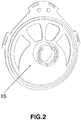
- the central axis 14 substantially perpendicular and integral with the bottom 3 , allows the guide of the roller 6 as well as the fitting and the maintenance of a closure / protection cover 15 ( Figure 2 ) lockable by rotation or any other equivalent mechanism.
- the closure cover 15 is thus removable.
- the side wall 2 comprises an outlet orifice 4 allowing the exit of the strip 5 when the roller 6 is placed in the housing 1 around the central axis 14.
- the outlet orifice 4 defines a first part (or a straight part ) and a second part (or a left part) of the side wall 2 on either side of this outlet orifice 4.
- the side wall 2 thus comprises a first part to the right of the outlet orifice 4 and a second part to the left of the outlet orifice 4.
- the first part and the second part of the side wall 2 are linked together by a support base 13 for the reel.
- the side wall 2 further comprises an inner strip guide 7 constraining the strip 5 in the axis of the outlet orifice 4.
- the first part (or the right part) of the side wall 2 comprises on its external face and at the edge of the outlet orifice 4 a first external strip guide 8 making it possible to guide the strip 5 when it is introduced therein.
- the second part (or the left part) of the side wall 2 comprises on its external face and at the edge of the outlet orifice 4 a second external strip guide 8b making it possible to guide the strip 5 when it is introduced therein.
- the first and second external strip guides 8 , 8b respectively, arranged on the first part and the second part of the side wall 2 are opposite each other on the outlet orifice 4.
- the first outer strip guide 8 allows the automatic separation of the pellets 9 from the strip 5 when it is inserted and pulled there as indicated by the arrow 10.
- the first outer strip guide 8 constrains, in fact, the strip 5 roll 6 to fold it at an angle allowing automatic separation of the patch 9 by pulling 10 on this strip 5.
- the strip 5 When it passes through the outlet orifice 4 and through the first or second outer strip guide 8 , 8b , the strip 5 is folded at an acute angle formed by the axis of the outlet orifice 4 and the axis according to which it is guided (or the path which is imposed on it) by the first or the second outer strip guide 8 , 8b.
- the pulling of the strip 5 constrained to follow this angle allows the automatic separation of the self-adhesive patch 9 from the strip 5.
- the example illustrated by figure 1 is that of a strip 5 introduced via the first outer strip guide 8 disposed on the right part (or the first part) of the side wall 2.
- the self-adhesive pads 9 are arranged on the outer face of the strip 5 and the roller 6 is unwound by rotating it around the central axis 14 in a clockwise direction.
- the distribution of these pellets 9 is obtained by maintaining the roller 6 in its position illustrated by the figure 1 and passing the strip 5 through the second outer strip guide 8b disposed on the left side of the side wall 2.
- one of the two outer tape guides 8 , 8b is still suitable for dispensing these self-adhesive pads 9 .
- first (respectively, second) outer strip guide 8 ( 8b ) of the right part (respectively, left) it suffices to have the roller 6 , when the self-adhesive pads 9 are placed on the outer face of the strip 5 , in the housing 1 so that this roller 6 must be turned around the central axis 14 in the direction (respectively, in the opposite direction) of the needles of a watch to be unwound.
- the strip 5 can be pulled either from the left or from the right of the reel.
- This reel can thus be used by right-handers or by left-handers.
- a third external strip guide 11 is arranged on the external face of the first part.
- a fourth external strip guide 11b is arranged on the external face of the second part.
- the third outer strip guide 11 is downstream of the first outer strip guide 8 relative to the direction of traction 10 of the strip 5 of the roller 6.
- the fourth outer strip guide 11b is downstream of the second outer strip guide relative to in the direction of traction of the strip 5 of the roller 6.
- the third and fourth outer strip guide 11 , 11b comprise, respectively, a cutting blade 12 , 12b allowing to cut the excess of the strip 5 from which the self-adhesive discs / stickers 9 have been removed.
- the housing is, in one embodiment, substantially symmetrical with respect to a plane comprising the central axis 14 and the axis of the outlet orifice 4.
- This reel can be coupled opposite with an identical reel by the outside face of the bottom 3 , allowing the use of two different colors of pads / stickers simultaneously.
- Coupling means are provided for this purpose in the bottom 3. These casting means may include any mechanical, magnetic, chemical fixing means or a combination of these means.
- the dispenser described above is intended for the storage and distribution of self-adhesive discs / stickers.
Description
La présente invention concerne un dispositif pour distribuer des pastilles autocollantes disposées sur une bande agencée en un rouleau selon la revendication 1.The present invention relates to a device for dispensing self-adhesive discs arranged on a strip arranged in a roll according to
Les rouleaux de pastilles/gommettes autocollantes sont généralement bruts ou en dévidoirs cartonnés qui n'ont pas de durabilité dans le temps.The rolls of self-adhesive pads / stickers are generally raw or in cardboard dispensers which have no durability over time.
Les rouleaux bruts se détériorent faute de support de stockage, et les éléments cartonnés n'ont pas de résistance dans le temps à cause des manipulations fréquentes.The raw rolls deteriorate due to the lack of storage medium, and the cardboard elements have no resistance over time due to frequent handling.
Le document
Des modes de réalisation décrits ci-dessous permettent de résoudre les inconvénients de l'art antérieur en permettant une extraction aisée desdites pastilles/gommettes par simple glissement avec le doigt de la bande support entre deux guides.Embodiments described below make it possible to solve the drawbacks of the prior art by allowing easy extraction of said pads / stickers by simple sliding with the finger of the support strip between two guides.
Cette bande support est guidée en sortie par un guide bande permettant la séparation automatique des pastilles/gommettes et par un autre guide avec une lame de coupe permettant de couper l'excédent de la bande support dont les pastilles/gommettes ont été enlevées.This support strip is guided at the outlet by a strip guide allowing the automatic separation of the pellets / stickers and by another guide with a cutting blade making it possible to cut the excess of the support strip from which the pellets / stickers have been removed.
Ce dévidoir possède un couvercle latéral verrouillable maintenant le rouleau dans son logement.This reel has a lockable side cover that keeps the roller in its housing.
Pour cela, il est proposé, en premier lieu, un dispositif pour distribuer des pastilles autocollantes disposées sur une bande agencée en un rouleau, ce dispositif comprenant un boitier intégrant un fond et une paroi latérale, le fond et la paroi latérale définissant un logement apte à recevoir, autour d'un axe central sensiblement perpendiculaire au fond, ledit rouleau, la paroi latérale comprenant un orifice de sortie pour la bande du rouleau, cet orifice de sortie définissant une première partie et une deuxième partie de la paroi latérale de part et d'autre de cet orifice de sortie, ce dispositif comprenant, en outre,
- un premier guide bande extérieur destiné à guider la bande du rouleau, ce premier guide bande extérieur étant disposé sur la face extérieure de la première partie au bord de l'orifice de sortie ;
- un deuxième guide bande extérieur destiné à guider la bande du rouleau, ce deuxième guide bande extérieur étant disposé sur la face extérieure de la deuxième partie au bord de l'orifice de sortie, le premier guide bande extérieur et le deuxième guide bande extérieur étant en regard de part et d'autre de l'orifice de sortie.
- a first external strip guide intended to guide the strip of the roll, this first external strip guide being arranged on the external face of the first part at the edge of the outlet orifice;
- a second outer strip guide intended to guide the strip of the roll, this second outer strip guide being arranged on the outer face of the second part at the edge of the outlet orifice, the first outer strip guide and the second outer strip guide being in look on either side of the outlet.
Diverses caractéristiques supplémentaires peuvent être prévues, seules ou en combinaison :
- le dispositif comprend, en outre, un troisième guide bande extérieur destiné à guider la bande du rouleau, ce troisième guide bande extérieur étant disposé sur la face extérieure de la première partie de la paroi latérale ;
- le troisième guide bande extérieur comprend une lame de coupe ;
- le dispositif comprend, en outre, un quatrième guide bande extérieur destiné à guider la bande du rouleau, ce quatrième guide bande extérieur étant disposé sur la face extérieure de la deuxième partie de la paroi latérale ;
- le quatrième guide bande extérieur comprend une lame de coupe ;
- le dispositif comprend, en outre, un guide bande intérieur destiné à contraindre la bande du rouleau dans l'axe de l'orifice de sortie ;
- la première partie et la deuxième partie sont liées entre-elles par une base d'appui ;
- le dispositif comprend, en outre, un couvercle de fermeture ;
- le fond du dispositif comprend ledit axe central, cet axe central étant destiné à permettre l'emboîtement du couvercle de fermeture ;
- le couvercle de fermeture est verrouillable par rotation sur l'axe central ;
- le dispositif est sensiblement symétrique par rapport à un plan comprenant l'axe central et l'axe de l'orifice de sortie ;
- l'axe de l'orifice de sortie forme avec l'axe suivant lequel le premier guide bande extérieur (8) est destiné à guider la bande un angle aigu ;
- l'axe de l'orifice de sortie forme avec l'axe suivant lequel le deuxième guide bande extérieur est destiné à guider la bande un angle aigu ;
- le fond comprend sur sa face extérieure un moyen de couplage destiné à permettre le couplage en vis-à-vis dudit dispositif à un deuxième dispositif identique par les faces extérieures de leurs fonds respectifs.
- the device further comprises a third external strip guide intended to guide the strip of the roller, this third external strip guide being arranged on the external face of the first part of the side wall;
- the third outer strip guide includes a cutting blade;
- the device further comprises a fourth external strip guide intended to guide the strip of the roll, this fourth external strip guide being arranged on the external face of the second part of the side wall;
- the fourth outer strip guide comprises a cutting blade;
- the device further comprises an internal strip guide intended to constrain the strip of the roller in the axis of the outlet orifice;
- the first part and the second part are linked together by a support base;
- the device further comprises a closure cover;
- the bottom of the device comprises said central axis, this central axis being intended to allow the interlocking of the closure cover;
- the closing cover is lockable by rotation on the central axis;
- the device is substantially symmetrical with respect to a plane comprising the central axis and the axis of the outlet orifice;
- the axis of the outlet orifice forms with the axis along which the first outer strip guide (8) is intended to guide the strip at an acute angle;
- the axis of the outlet orifice forms with the axis along which the second outer strip guide is intended to guide the strip at an acute angle;
- the bottom comprises on its outer face a coupling means intended to allow the coupling opposite of said device to a second device identical by the outer faces of their respective bottoms.
Il est proposé, en second lieu, un ensemble comprenant le dispositif ci-dessus et un deuxième dispositif qui lui est identique, ces deux dispositifs étant couplés en vis-à-vis par les faces extérieures de leurs fonds respectifs.It is proposed, secondly, an assembly comprising the above device and a second device which is identical to it, these two devices being coupled vis-à-vis by the outer faces of their respective bottoms.
D'autres caractéristiques et avantages de l'invention apparaîtront plus clairement et de manière concrète à la lecture de la description ci-après de modes de réalisation, laquelle est faite en référence aux dessins annexés dans lesquels :
- la
figure 1 représente un dévidoir vu en perspective. - la
figure 2 représente le couvercle du dévidoir vu en perspective.
- the
figure 1 represents a reel seen in perspective. - the
figure 2 represents the cover of the reel seen in perspective.
En référence à la
La paroi latérale 2 et le fond 3 définissent un logement apte à recevoir, autour d'un axe central 14 sensiblement perpendiculaire au fond 3, une bande 5 agencée en un rouleau 6 et sur laquelle sont disposés des pastilles 9 autocollantes. Le rouleau 6 est libre en rotation autour de l'axe central 14. The
L'axe central 14, sensiblement perpendiculaire et solidaire au fond 3, permet le guidage du rouleau 6 ainsi que l'emboîtement et le maintien d'un couvercle de fermeture/protection 15 (
La paroi latérale 2 comprend un orifice de sortie 4 permettant la sortie de la bande 5 lorsque le rouleau 6 est disposé dans le boitier 1 autour de l'axe central 14. L'orifice de sortie 4 définit une première partie (ou une partie droite) et une deuxième partie (ou une partie gauche) de la paroi latérale 2 de part et d'autre de cet orifice de sortie 4. La paroi latérale 2 comprend, ainsi, une première partie à droite de l'orifice de sortie 4 et une deuxième partie à gauche de l'orifice de sortie 4. The
La première partie et la deuxième partie de la paroi latérale 2 sont liées entre-elles par une base d'appui 13 pour le dévidoir.The first part and the second part of the
La paroi latérale 2 comprend, en outre, un guide bande intérieur 7 contraignant la bande 5 dans l'axe de l'orifice de sortie 4. The
La première partie (ou la partie droite) de la paroi latérale 2 comprend sur sa face extérieure et au bord de l'orifice de sortie 4 un premier guide bande extérieur 8 permettant de guider la bande 5 lorsqu'elle y est introduite. De même, la deuxième partie (ou la partie gauche) de la paroi latérale 2 comprend sur sa face extérieure et au bord de l'orifice de sortie 4 un deuxième guide bande extérieur 8b permettant de guider la bande 5 lorsqu'elle y est introduite. Le premier et deuxième guides bande extérieurs 8, 8b, respectivement, disposés sur la première partie et la deuxième partie de la paroi latérale 2 sont en regard de part et d'autre de l'orifice de sortie 4. The first part (or the right part) of the
Le premier guide bande extérieur 8 permet la séparation automatique des pastilles 9 de la bande 5 lorsqu'elle y est introduite et tirée tel qu'il est indiqué par la flèche 10. Le premier guide bande extérieur 8 contraint, en effet, la bande 5 du rouleau 6 pour la plier selon un angle permettant la séparation automatique de la pastille 9 en effectuant une traction 10 sur cette bande 5. The first
Lorsqu'elle passe par l'orifice de sortie 4 et par le premier ou le deuxième guide bande extérieur 8, 8b, la bande 5 est pliée selon un angle aigu formé par l'axe de l'orifice de sortie 4 et l'axe suivant lequel elle est guidée (ou la trajectoire qui lui est imposée) par le premier ou le deuxième guide bande extérieur 8, 8b. Le tirage de la bande 5 contrainte de suivre cet angle permet la séparation automatique de la pastille 9 autocollante de la bande 5. When it passes through the
L'exemple illustré par la
Plus généralement, indépendamment de la disposition du rouleau 6 dans le boitier (c.à.d. de son sens de rotation pour être dévidé) et de la face (intérieure ou extérieure) de la bande 5 sur laquelle sont disposées les pastilles 9 autocollantes, un des deux guides bande extérieurs 8, 8b est toujours convenable pour la distribution de ces pastilles 9 autocollantes.More generally, independently of the arrangement of the
Par ailleurs, pour utiliser le premier (respectivement, deuxième) guide bande extérieur 8 (8b) de la partie droite (respectivement, gauche), il suffit de disposer le rouleau 6, lorsque les pastilles 9 autocollantes sont disposées sur la face extérieure de la bande 5, dans le boitier 1 de sorte que ce rouleau 6 doit être tourné autour de l'axe central 14 dans le sens (respectivement, dans le sens contraire) des aiguilles d'une montre pour être déroulé.Furthermore, to use the first (respectively, second) outer strip guide 8 ( 8b ) of the right part (respectively, left), it suffices to have the
Il en résulte que la bande 5 peut être tirée soit par la gauche ou par la droite du dévidoir. Ce dévidoir peut, ainsi, être utilisé par des droitiers ou par des gauchers.As a result, the
Dans un mode de réalisation, un troisième guide bande extérieur 11 est disposé sur la face extérieure de la première partie. De même, un quatrième guide bande extérieur 11b est disposé sur la face extérieur de la deuxième partie.In one embodiment, a third
Le troisième guide bande extérieur 11 est en aval du premier guide bande extérieur 8 par rapport au sens de la traction 10 de la bande 5 du rouleau 6. De même, le quatrième guide bande extérieur 11b est en aval du deuxième guide bande extérieur par rapport au sens de la traction de la bande 5 du rouleau 6. The third
Le troisième et quatrième guide bande extérieurs 11, 11b comprennent, respectivement, une lame de coupe 12, 12b permettant de couper l'excédent de la bande 5 dont les pastilles/gommettes 9 autocollantes ont été enlevées.The third and fourth
Le boitier est, dans un mode de réalisation, sensiblement symétrique par rapport à un plan comprenant l'axe central 14 et l'axe de l'orifice de sortie 4. The housing is, in one embodiment, substantially symmetrical with respect to a plane comprising the
Ce dévidoir peut être couplé en vis à vis avec un dévidoir identique par la face extérieur du fond 3, permettant d'utiliser deux couleurs différentes de pastilles/gommettes simultanément. Des moyens de couplage sont prévus à cet effet dans le fond 3. Ces moyens de coulage peuvent comprendre tout moyen de fixation mécanique, magnétique, chimique ou une combinaison de ces moyens.This reel can be coupled opposite with an identical reel by the outside face of the
Le dévidoir décrit ci-dessus est destiné au stockage et à la distribution de pastilles/gommettes autocollantes.The dispenser described above is intended for the storage and distribution of self-adhesive discs / stickers.
Claims (15)
- A device for dispensing self-adhesives stickers (9) disposed on a strip (5) arranged as a roller (6), this device comprising a case (1) having a bottom (3) and a side wall (2), the bottom (3) and the side wall (2) defining a housing able to receive, around a centre axis (14) substantially perpendicular to the bottom (3), said roller (6), the side wall (2) comprising an outlet port (4) for the strip (5) of the roller (6), this outlet port (4) defining a first part and a second part of the side wall (2) on either side of this outlet port (4), this device being characterised in that it further comprises,- a first external strip guide (8) for guiding the strip (5) of the roller (6), this first external strip guide (8) being disposed on the external face of the first part at the edge of the outlet port (4);- a second external strip guide (8b) for guiding the strip (5) of the roller (6), this second external strip guide (8b) being disposed on the external face of the second part at the edge of the outlet port(4), the first external strip guide(8) and the second external strip guide (8b) facing each other on either side of the outlet port (4).
- The device according to the previous claim, characterised in that it further comprises a third external strip guide (11) for guiding the strip (5) of the roller (6), this third external strip guide (11) being disposed on the external face of the first part of the side wall (2).
- The device according to the previous claim, characterised in that the third external strip guide (11) comprises a cutting blade (12).
- The device according to claim 2, characterised in that it further comprises, a fourth external strip guide (11b) for guiding the strip (5) of the roller (6), this fourth external strip guide (11b) being disposed on the external face of the second part of the side wall (2).
- The device according to the previous claim, characterised in that the fourth external strip guide (11b) comprises a cutting blade (12b).
- The device according to any of the previous claims, characterised in that it further comprises an internal strip guide (7) for restraining the strip (5) of the roller (6) along the axis of the outlet port (4).
- The device according to any of the previous claims, characterised in that the first part and the second part are connected to each other by a support base (13).
- The device according to any of the previous claims, characterised in that it further comprises a closing lid (15).
- The device according to the previous claim, characterised in that the bottom (3) comprises said centre axis (14), this centre axis (14) being for interlocking the closing lid (15).
- The device according to claim 8 or 9, characterised in that the closing lid (15) is rotatably lockable about the centre axis (14).
- The device according to any of the previous claims, characterised in that it is substantially symmetrical relative to a plane comprising the centre axis (14) and the axis of the outlet port (4).
- The device according to any of the previous claims, characterised in that the axis of the outlet port (4) forms an acute angle with the axis along which the first external strip guide (8) is to guide the strip (5).
- The device according to any of the previous claims, characterised in that the axis of the outlet port (4) forms an acute angle with the axis along which the second external strip guide (8b) is to guide the strip (5).
- The device according to any of the previous claims, characterised in that the bottom (3) comprises on its external face a coupling means for enabling said device to be face-to-face coupled with a second identical device by the external faces of their respective bottoms (3).
- An assembly comprising a first device according to the previous claim and a second device according to the previous claim, the first device being face-to-face coupled with the second device by the external faces of their respective bottoms (3).
Applications Claiming Priority (1)
| Application Number | Priority Date | Filing Date | Title |
|---|---|---|---|
| FR1770407A FR3056974B1 (en) | 2017-04-21 | 2017-04-21 | GUNETTE TOWEL-2 |
Publications (2)
| Publication Number | Publication Date |
|---|---|
| EP3392175A1 EP3392175A1 (en) | 2018-10-24 |
| EP3392175B1 true EP3392175B1 (en) | 2020-03-18 |
Family
ID=59381582
Family Applications (1)
| Application Number | Title | Priority Date | Filing Date |
|---|---|---|---|
| EP18164279.4A Active EP3392175B1 (en) | 2017-04-21 | 2018-03-27 | Dispenser |
Country Status (3)
| Country | Link |
|---|---|
| US (1) | US20180305163A1 (en) |
| EP (1) | EP3392175B1 (en) |
| FR (1) | FR3056974B1 (en) |
Family Cites Families (21)
| Publication number | Priority date | Publication date | Assignee | Title |
|---|---|---|---|---|
| US2569140A (en) * | 1946-04-04 | 1951-09-25 | Adhesive Dev Co | Adhesive label and tape dispenser and applicator |
| US2912140A (en) * | 1957-03-07 | 1959-11-10 | Kleen Stik Products Inc | Label dispenser |
| US3140217A (en) * | 1960-07-20 | 1964-07-07 | Jerry L Molinari | Masking tape applicator |
| US3793123A (en) * | 1972-05-31 | 1974-02-19 | M Aronson | Label dispenser |
| US4093494A (en) * | 1977-05-09 | 1978-06-06 | W Boettcher | Securing means for parquet floor boards |
| US4954208A (en) * | 1982-08-16 | 1990-09-04 | Monarch Marking Systems, Inc. | Hand-held labeller |
| US4619727A (en) * | 1982-08-16 | 1986-10-28 | Monarch Marking Systems, Inc. | Hand-held labeler |
| US4496049A (en) * | 1983-04-12 | 1985-01-29 | Monarch Marking Systems, Inc. | Label roll holder for hand-held labeler, holder blank, and method of making same |
| US4467974A (en) * | 1983-02-14 | 1984-08-28 | Crim Frank T | Bathroom tissue dispenser |
| US4824517A (en) * | 1987-08-20 | 1989-04-25 | Dennison Manufacturing Company | Multipurpose dispenser |
| US4772355A (en) * | 1987-08-20 | 1988-09-20 | Dennison Manufacturing Company | Multipurpose dispenser |
| DE4302107A1 (en) * | 1993-01-27 | 1994-07-28 | Minnesota Mining & Mfg | Tape dispenser, in particular tape dispenser |
| GB9324436D0 (en) * | 1993-11-27 | 1994-01-12 | Ryford Ltd | Tape dispenser |
| US5378301A (en) * | 1994-01-18 | 1995-01-03 | Moore Business Forms, Inc. | Linerless label dispensing |
| US5806713A (en) * | 1996-04-29 | 1998-09-15 | Dudley; Peter B. | Self-adhesive stamp dispensing device |
| US5851348A (en) * | 1997-04-28 | 1998-12-22 | Barbara Thomas Enterprises, Inc. | Dispenser for tags, labels, indexing tabs and the like |
| US6213343B1 (en) * | 1998-10-13 | 2001-04-10 | Avery Dennison Corporation | Portable sterile bandage dispenser |
| US7905371B1 (en) * | 2007-08-22 | 2011-03-15 | Victor Mohoney | Label dispenser |
| AP3461A (en) * | 2010-03-22 | 2015-11-30 | Wrigley W M Jun Co | Multi-piece dispenser for use with a consumable product |
| US8851284B2 (en) * | 2011-05-18 | 2014-10-07 | Thuban, Inc. | Adhesive bandage dispensing arrangements |
| US20150238376A1 (en) * | 2014-02-21 | 2015-08-27 | Jody Seibold | Adhesive bandage dispensing device |
-
2017
- 2017-04-21 FR FR1770407A patent/FR3056974B1/en active Active
-
2018
- 2018-03-27 EP EP18164279.4A patent/EP3392175B1/en active Active
- 2018-04-19 US US15/957,020 patent/US20180305163A1/en not_active Abandoned
Non-Patent Citations (1)
| Title |
|---|
| None * |
Also Published As
| Publication number | Publication date |
|---|---|
| US20180305163A1 (en) | 2018-10-25 |
| FR3056974B1 (en) | 2018-11-23 |
| EP3392175A1 (en) | 2018-10-24 |
| FR3056974A1 (en) | 2018-04-06 |
Similar Documents
| Publication | Publication Date | Title |
|---|---|---|
| US5593035A (en) | Protective case for rolls of sheet material | |
| EP1941821A1 (en) | Dispenser with rollers arranged side by side and equipped with a bottom sliding trapdoor | |
| EP3392175B1 (en) | Dispenser | |
| EP1163872B1 (en) | Charging device for wiping material dispenser | |
| FR2538582A1 (en) | MECHANISM FOR COUNTING THE NUMBER OF PAPER SHEETS | |
| FR2482863A1 (en) | APPARATUS FOR RECLAIMING THE WINDING OF AN INDIVIDUAL BELT OF SAFETY, BY SPRING, IN NON-USE IN A MOTOR VEHICLE | |
| FR2518517A1 (en) | DEVICE FOR ALIGNING AND BANDING A STACK OF PAPER SHEETS | |
| JPH1067460A (en) | Tape dispenser box in particular for adhesive tape | |
| BE1010326A3 (en) | Storage device for media information. | |
| FR2689674A1 (en) | Magnetic tape cartridge with primer block lock mechanism. | |
| FR2487302A1 (en) | DEVICE FOR DISTRIBUTING ONE TO ONE OF OBJECTS | |
| FR2570539A1 (en) | MAGNETIC TAPE CASSETTE WITH REMAINING LENGTH INDICATOR | |
| CH682775A5 (en) | Card reader. | |
| EP0022694B1 (en) | Holder for a stack of sheets in a sheet distributing machine | |
| EP1106773A1 (en) | Mounting device for a drive, and an actuating device for closures or sun screens comprising such a device | |
| FR2816288A1 (en) | FLUID PRODUCT DISPENSER | |
| EP0889700B1 (en) | Apparatus for dispensing optionally folded wiping materials | |
| EP1346659A2 (en) | Dispensing device for flat objects of different series | |
| FR2627071A1 (en) | Dispenser of a strip of material in the form of a roll | |
| EP1902427A1 (en) | Machine for dispensing products and/or services, which is equipped with a banknote reader | |
| FR2699904A1 (en) | Distributor for roll of cleaning paper | |
| EP0457731B1 (en) | Dispenser for toilet paper in rolls | |
| WO1998005514A2 (en) | Device for folding letter paper | |
| EP4188833A1 (en) | On/off type diffuser | |
| FR2832794A1 (en) | Tape measure has graduated tape with end hook carried on sprung drum which is contained within clip together twin shell casing provided with aperture to view inscription on side of drum |
Legal Events
| Date | Code | Title | Description |
|---|---|---|---|
| PUAI | Public reference made under article 153(3) epc to a published international application that has entered the european phase |
Free format text: ORIGINAL CODE: 0009012 |
|
| STAA | Information on the status of an ep patent application or granted ep patent |
Free format text: STATUS: THE APPLICATION HAS BEEN PUBLISHED |
|
| AK | Designated contracting states |
Kind code of ref document: A1 Designated state(s): AL AT BE BG CH CY CZ DE DK EE ES FI FR GB GR HR HU IE IS IT LI LT LU LV MC MK MT NL NO PL PT RO RS SE SI SK SM TR |
|
| AX | Request for extension of the european patent |
Extension state: BA ME |
|
| STAA | Information on the status of an ep patent application or granted ep patent |
Free format text: STATUS: REQUEST FOR EXAMINATION WAS MADE |
|
| 17P | Request for examination filed |
Effective date: 20190125 |
|
| RBV | Designated contracting states (corrected) |
Designated state(s): AL AT BE BG CH CY CZ DE DK EE ES FI FR GB GR HR HU IE IS IT LI LT LU LV MC MK MT NL NO PL PT RO RS SE SI SK SM TR |
|
| RIC1 | Information provided on ipc code assigned before grant |
Ipc: B65H 35/00 20060101ALI20190521BHEP Ipc: B65H 37/00 20060101AFI20190521BHEP |
|
| GRAP | Despatch of communication of intention to grant a patent |
Free format text: ORIGINAL CODE: EPIDOSNIGR1 |
|
| STAA | Information on the status of an ep patent application or granted ep patent |
Free format text: STATUS: GRANT OF PATENT IS INTENDED |
|
| INTG | Intention to grant announced |
Effective date: 20190710 |
|
| GRAA | (expected) grant |
Free format text: ORIGINAL CODE: 0009210 |
|
| GRAS | Grant fee paid |
Free format text: ORIGINAL CODE: EPIDOSNIGR3 |
|
| STAA | Information on the status of an ep patent application or granted ep patent |
Free format text: STATUS: THE PATENT HAS BEEN GRANTED |
|
| AK | Designated contracting states |
Kind code of ref document: B1 Designated state(s): AL AT BE BG CH CY CZ DE DK EE ES FI FR GB GR HR HU IE IS IT LI LT LU LV MC MK MT NL NO PL PT RO RS SE SI SK SM TR |
|
| REG | Reference to a national code |
Ref country code: GB Ref legal event code: FG4D Free format text: NOT ENGLISH |
|
| REG | Reference to a national code |
Ref country code: DE Ref legal event code: R096 Ref document number: 602018003051 Country of ref document: DE |
|
| REG | Reference to a national code |
Ref country code: AT Ref legal event code: REF Ref document number: 1245694 Country of ref document: AT Kind code of ref document: T Effective date: 20200415 Ref country code: IE Ref legal event code: FG4D Free format text: LANGUAGE OF EP DOCUMENT: FRENCH |
|
| PG25 | Lapsed in a contracting state [announced via postgrant information from national office to epo] |
Ref country code: NO Free format text: LAPSE BECAUSE OF FAILURE TO SUBMIT A TRANSLATION OF THE DESCRIPTION OR TO PAY THE FEE WITHIN THE PRESCRIBED TIME-LIMIT Effective date: 20200618 Ref country code: RS Free format text: LAPSE BECAUSE OF FAILURE TO SUBMIT A TRANSLATION OF THE DESCRIPTION OR TO PAY THE FEE WITHIN THE PRESCRIBED TIME-LIMIT Effective date: 20200318 Ref country code: FI Free format text: LAPSE BECAUSE OF FAILURE TO SUBMIT A TRANSLATION OF THE DESCRIPTION OR TO PAY THE FEE WITHIN THE PRESCRIBED TIME-LIMIT Effective date: 20200318 |
|
| REG | Reference to a national code |
Ref country code: NL Ref legal event code: MP Effective date: 20200318 |
|
| PG25 | Lapsed in a contracting state [announced via postgrant information from national office to epo] |
Ref country code: GR Free format text: LAPSE BECAUSE OF FAILURE TO SUBMIT A TRANSLATION OF THE DESCRIPTION OR TO PAY THE FEE WITHIN THE PRESCRIBED TIME-LIMIT Effective date: 20200619 Ref country code: BG Free format text: LAPSE BECAUSE OF FAILURE TO SUBMIT A TRANSLATION OF THE DESCRIPTION OR TO PAY THE FEE WITHIN THE PRESCRIBED TIME-LIMIT Effective date: 20200618 Ref country code: HR Free format text: LAPSE BECAUSE OF FAILURE TO SUBMIT A TRANSLATION OF THE DESCRIPTION OR TO PAY THE FEE WITHIN THE PRESCRIBED TIME-LIMIT Effective date: 20200318 Ref country code: LV Free format text: LAPSE BECAUSE OF FAILURE TO SUBMIT A TRANSLATION OF THE DESCRIPTION OR TO PAY THE FEE WITHIN THE PRESCRIBED TIME-LIMIT Effective date: 20200318 Ref country code: SE Free format text: LAPSE BECAUSE OF FAILURE TO SUBMIT A TRANSLATION OF THE DESCRIPTION OR TO PAY THE FEE WITHIN THE PRESCRIBED TIME-LIMIT Effective date: 20200318 |
|
| REG | Reference to a national code |
Ref country code: LT Ref legal event code: MG4D |
|
| PG25 | Lapsed in a contracting state [announced via postgrant information from national office to epo] |
Ref country code: NL Free format text: LAPSE BECAUSE OF FAILURE TO SUBMIT A TRANSLATION OF THE DESCRIPTION OR TO PAY THE FEE WITHIN THE PRESCRIBED TIME-LIMIT Effective date: 20200318 |
|
| PG25 | Lapsed in a contracting state [announced via postgrant information from national office to epo] |
Ref country code: IS Free format text: LAPSE BECAUSE OF FAILURE TO SUBMIT A TRANSLATION OF THE DESCRIPTION OR TO PAY THE FEE WITHIN THE PRESCRIBED TIME-LIMIT Effective date: 20200718 Ref country code: SK Free format text: LAPSE BECAUSE OF FAILURE TO SUBMIT A TRANSLATION OF THE DESCRIPTION OR TO PAY THE FEE WITHIN THE PRESCRIBED TIME-LIMIT Effective date: 20200318 Ref country code: SM Free format text: LAPSE BECAUSE OF FAILURE TO SUBMIT A TRANSLATION OF THE DESCRIPTION OR TO PAY THE FEE WITHIN THE PRESCRIBED TIME-LIMIT Effective date: 20200318 Ref country code: LT Free format text: LAPSE BECAUSE OF FAILURE TO SUBMIT A TRANSLATION OF THE DESCRIPTION OR TO PAY THE FEE WITHIN THE PRESCRIBED TIME-LIMIT Effective date: 20200318 Ref country code: CZ Free format text: LAPSE BECAUSE OF FAILURE TO SUBMIT A TRANSLATION OF THE DESCRIPTION OR TO PAY THE FEE WITHIN THE PRESCRIBED TIME-LIMIT Effective date: 20200318 Ref country code: RO Free format text: LAPSE BECAUSE OF FAILURE TO SUBMIT A TRANSLATION OF THE DESCRIPTION OR TO PAY THE FEE WITHIN THE PRESCRIBED TIME-LIMIT Effective date: 20200318 Ref country code: EE Free format text: LAPSE BECAUSE OF FAILURE TO SUBMIT A TRANSLATION OF THE DESCRIPTION OR TO PAY THE FEE WITHIN THE PRESCRIBED TIME-LIMIT Effective date: 20200318 Ref country code: PT Free format text: LAPSE BECAUSE OF FAILURE TO SUBMIT A TRANSLATION OF THE DESCRIPTION OR TO PAY THE FEE WITHIN THE PRESCRIBED TIME-LIMIT Effective date: 20200812 |
|
| REG | Reference to a national code |
Ref country code: AT Ref legal event code: MK05 Ref document number: 1245694 Country of ref document: AT Kind code of ref document: T Effective date: 20200318 |
|
| REG | Reference to a national code |
Ref country code: DE Ref legal event code: R097 Ref document number: 602018003051 Country of ref document: DE |
|
| PG25 | Lapsed in a contracting state [announced via postgrant information from national office to epo] |
Ref country code: MC Free format text: LAPSE BECAUSE OF FAILURE TO SUBMIT A TRANSLATION OF THE DESCRIPTION OR TO PAY THE FEE WITHIN THE PRESCRIBED TIME-LIMIT Effective date: 20200318 Ref country code: LU Free format text: LAPSE BECAUSE OF NON-PAYMENT OF DUE FEES Effective date: 20200327 |
|
| PLBE | No opposition filed within time limit |
Free format text: ORIGINAL CODE: 0009261 |
|
| STAA | Information on the status of an ep patent application or granted ep patent |
Free format text: STATUS: NO OPPOSITION FILED WITHIN TIME LIMIT |
|
| PG25 | Lapsed in a contracting state [announced via postgrant information from national office to epo] |
Ref country code: IE Free format text: LAPSE BECAUSE OF NON-PAYMENT OF DUE FEES Effective date: 20200327 Ref country code: DK Free format text: LAPSE BECAUSE OF FAILURE TO SUBMIT A TRANSLATION OF THE DESCRIPTION OR TO PAY THE FEE WITHIN THE PRESCRIBED TIME-LIMIT Effective date: 20200318 Ref country code: ES Free format text: LAPSE BECAUSE OF FAILURE TO SUBMIT A TRANSLATION OF THE DESCRIPTION OR TO PAY THE FEE WITHIN THE PRESCRIBED TIME-LIMIT Effective date: 20200318 Ref country code: IT Free format text: LAPSE BECAUSE OF FAILURE TO SUBMIT A TRANSLATION OF THE DESCRIPTION OR TO PAY THE FEE WITHIN THE PRESCRIBED TIME-LIMIT Effective date: 20200318 Ref country code: AT Free format text: LAPSE BECAUSE OF FAILURE TO SUBMIT A TRANSLATION OF THE DESCRIPTION OR TO PAY THE FEE WITHIN THE PRESCRIBED TIME-LIMIT Effective date: 20200318 |
|
| 26N | No opposition filed |
Effective date: 20201221 |
|
| PG25 | Lapsed in a contracting state [announced via postgrant information from national office to epo] |
Ref country code: PL Free format text: LAPSE BECAUSE OF FAILURE TO SUBMIT A TRANSLATION OF THE DESCRIPTION OR TO PAY THE FEE WITHIN THE PRESCRIBED TIME-LIMIT Effective date: 20200318 |
|
| PG25 | Lapsed in a contracting state [announced via postgrant information from national office to epo] |
Ref country code: SI Free format text: LAPSE BECAUSE OF FAILURE TO SUBMIT A TRANSLATION OF THE DESCRIPTION OR TO PAY THE FEE WITHIN THE PRESCRIBED TIME-LIMIT Effective date: 20200318 |
|
| REG | Reference to a national code |
Ref country code: CH Ref legal event code: PL |
|
| PG25 | Lapsed in a contracting state [announced via postgrant information from national office to epo] |
Ref country code: CH Free format text: LAPSE BECAUSE OF NON-PAYMENT OF DUE FEES Effective date: 20210331 Ref country code: LI Free format text: LAPSE BECAUSE OF NON-PAYMENT OF DUE FEES Effective date: 20210331 |
|
| PGFP | Annual fee paid to national office [announced via postgrant information from national office to epo] |
Ref country code: DE Payment date: 20220217 Year of fee payment: 5 |
|
| PG25 | Lapsed in a contracting state [announced via postgrant information from national office to epo] |
Ref country code: TR Free format text: LAPSE BECAUSE OF FAILURE TO SUBMIT A TRANSLATION OF THE DESCRIPTION OR TO PAY THE FEE WITHIN THE PRESCRIBED TIME-LIMIT Effective date: 20200318 Ref country code: MT Free format text: LAPSE BECAUSE OF FAILURE TO SUBMIT A TRANSLATION OF THE DESCRIPTION OR TO PAY THE FEE WITHIN THE PRESCRIBED TIME-LIMIT Effective date: 20200318 Ref country code: CY Free format text: LAPSE BECAUSE OF FAILURE TO SUBMIT A TRANSLATION OF THE DESCRIPTION OR TO PAY THE FEE WITHIN THE PRESCRIBED TIME-LIMIT Effective date: 20200318 |
|
| PGFP | Annual fee paid to national office [announced via postgrant information from national office to epo] |
Ref country code: FR Payment date: 20220308 Year of fee payment: 5 Ref country code: BE Payment date: 20220217 Year of fee payment: 5 |
|
| PG25 | Lapsed in a contracting state [announced via postgrant information from national office to epo] |
Ref country code: MK Free format text: LAPSE BECAUSE OF FAILURE TO SUBMIT A TRANSLATION OF THE DESCRIPTION OR TO PAY THE FEE WITHIN THE PRESCRIBED TIME-LIMIT Effective date: 20200318 Ref country code: AL Free format text: LAPSE BECAUSE OF FAILURE TO SUBMIT A TRANSLATION OF THE DESCRIPTION OR TO PAY THE FEE WITHIN THE PRESCRIBED TIME-LIMIT Effective date: 20200318 |
|
| GBPC | Gb: european patent ceased through non-payment of renewal fee |
Effective date: 20220327 |
|
| PG25 | Lapsed in a contracting state [announced via postgrant information from national office to epo] |
Ref country code: GB Free format text: LAPSE BECAUSE OF NON-PAYMENT OF DUE FEES Effective date: 20220327 |
|
| REG | Reference to a national code |
Ref country code: DE Ref legal event code: R119 Ref document number: 602018003051 Country of ref document: DE |
|
| REG | Reference to a national code |
Ref country code: BE Ref legal event code: MM Effective date: 20230331 |
|
| PG25 | Lapsed in a contracting state [announced via postgrant information from national office to epo] |
Ref country code: FR Free format text: LAPSE BECAUSE OF NON-PAYMENT OF DUE FEES Effective date: 20230331 Ref country code: DE Free format text: LAPSE BECAUSE OF NON-PAYMENT OF DUE FEES Effective date: 20231003 |
|
| PG25 | Lapsed in a contracting state [announced via postgrant information from national office to epo] |
Ref country code: BE Free format text: LAPSE BECAUSE OF NON-PAYMENT OF DUE FEES Effective date: 20230331 |