EP3392113B1 - Railway wagon for transporting trucks and method for loading and unloading truck - Google Patents
Railway wagon for transporting trucks and method for loading and unloading truck Download PDFInfo
- Publication number
- EP3392113B1 EP3392113B1 EP16874740.0A EP16874740A EP3392113B1 EP 3392113 B1 EP3392113 B1 EP 3392113B1 EP 16874740 A EP16874740 A EP 16874740A EP 3392113 B1 EP3392113 B1 EP 3392113B1
- Authority
- EP
- European Patent Office
- Prior art keywords
- plate
- running
- running plate
- railway wagon
- truck
- Prior art date
- Legal status (The legal status is an assumption and is not a legal conclusion. Google has not performed a legal analysis and makes no representation as to the accuracy of the status listed.)
- Active
Links
- 238000011068 loading method Methods 0.000 title claims description 18
- 238000000034 method Methods 0.000 title claims description 13
- 230000000712 assembly Effects 0.000 claims description 44
- 238000000429 assembly Methods 0.000 claims description 44
- 238000010586 diagram Methods 0.000 description 10
- 229910000838 Al alloy Inorganic materials 0.000 description 5
- 239000010959 steel Substances 0.000 description 3
- 229910000851 Alloy steel Inorganic materials 0.000 description 2
- 206010039203 Road traffic accident Diseases 0.000 description 1
- 229910000831 Steel Inorganic materials 0.000 description 1
- 239000000446 fuel Substances 0.000 description 1
- 230000032258 transport Effects 0.000 description 1
Images


Classifications
-
- B—PERFORMING OPERATIONS; TRANSPORTING
- B61—RAILWAYS
- B61D—BODY DETAILS OR KINDS OF RAILWAY VEHICLES
- B61D3/00—Wagons or vans
- B61D3/16—Wagons or vans adapted for carrying special loads
- B61D3/18—Wagons or vans adapted for carrying special loads for vehicles
- B61D3/182—Wagons or vans adapted for carrying special loads for vehicles specially adapted for heavy vehicles, e.g. public work vehicles, trucks, trailers
-
- B—PERFORMING OPERATIONS; TRANSPORTING
- B60—VEHICLES IN GENERAL
- B60P—VEHICLES ADAPTED FOR LOAD TRANSPORTATION OR TO TRANSPORT, TO CARRY, OR TO COMPRISE SPECIAL LOADS OR OBJECTS
- B60P3/00—Vehicles adapted to transport, to carry or to comprise special loads or objects
- B60P3/06—Vehicles adapted to transport, to carry or to comprise special loads or objects for carrying vehicles
- B60P3/07—Vehicles adapted to transport, to carry or to comprise special loads or objects for carrying vehicles for carrying road vehicles
-
- B—PERFORMING OPERATIONS; TRANSPORTING
- B60—VEHICLES IN GENERAL
- B60P—VEHICLES ADAPTED FOR LOAD TRANSPORTATION OR TO TRANSPORT, TO CARRY, OR TO COMPRISE SPECIAL LOADS OR OBJECTS
- B60P3/00—Vehicles adapted to transport, to carry or to comprise special loads or objects
- B60P3/06—Vehicles adapted to transport, to carry or to comprise special loads or objects for carrying vehicles
- B60P3/08—Multilevel-deck construction carrying vehicles
-
- B—PERFORMING OPERATIONS; TRANSPORTING
- B61—RAILWAYS
- B61D—BODY DETAILS OR KINDS OF RAILWAY VEHICLES
- B61D3/00—Wagons or vans
- B61D3/16—Wagons or vans adapted for carrying special loads
-
- B—PERFORMING OPERATIONS; TRANSPORTING
- B61—RAILWAYS
- B61D—BODY DETAILS OR KINDS OF RAILWAY VEHICLES
- B61D3/00—Wagons or vans
- B61D3/16—Wagons or vans adapted for carrying special loads
- B61D3/166—Wagons or vans adapted for carrying special loads for carrying very heavy loads
-
- B—PERFORMING OPERATIONS; TRANSPORTING
- B61—RAILWAYS
- B61D—BODY DETAILS OR KINDS OF RAILWAY VEHICLES
- B61D3/00—Wagons or vans
- B61D3/16—Wagons or vans adapted for carrying special loads
- B61D3/18—Wagons or vans adapted for carrying special loads for vehicles
-
- B—PERFORMING OPERATIONS; TRANSPORTING
- B61—RAILWAYS
- B61D—BODY DETAILS OR KINDS OF RAILWAY VEHICLES
- B61D3/00—Wagons or vans
- B61D3/16—Wagons or vans adapted for carrying special loads
- B61D3/18—Wagons or vans adapted for carrying special loads for vehicles
- B61D3/182—Wagons or vans adapted for carrying special loads for vehicles specially adapted for heavy vehicles, e.g. public work vehicles, trucks, trailers
- B61D3/184—Wagons or vans adapted for carrying special loads for vehicles specially adapted for heavy vehicles, e.g. public work vehicles, trucks, trailers the heavy vehicles being of the trailer or semi-trailer type
-
- B—PERFORMING OPERATIONS; TRANSPORTING
- B61—RAILWAYS
- B61D—BODY DETAILS OR KINDS OF RAILWAY VEHICLES
- B61D3/00—Wagons or vans
- B61D3/16—Wagons or vans adapted for carrying special loads
- B61D3/18—Wagons or vans adapted for carrying special loads for vehicles
- B61D3/187—Details, e.g. bridges for floor connections
- B61D3/188—Wheel guides for the vehicles being carried
-
- B—PERFORMING OPERATIONS; TRANSPORTING
- B61—RAILWAYS
- B61D—BODY DETAILS OR KINDS OF RAILWAY VEHICLES
- B61D47/00—Loading or unloading devices combined with vehicles, e.g. loading platforms, doors convertible into loading and unloading ramps
-
- B—PERFORMING OPERATIONS; TRANSPORTING
- B61—RAILWAYS
- B61D—BODY DETAILS OR KINDS OF RAILWAY VEHICLES
- B61D47/00—Loading or unloading devices combined with vehicles, e.g. loading platforms, doors convertible into loading and unloading ramps
- B61D47/005—Loading or unloading devices combined with road vehicles carrying wagons, e.g. ramps, turntables, lifting means
-
- B—PERFORMING OPERATIONS; TRANSPORTING
- B63—SHIPS OR OTHER WATERBORNE VESSELS; RELATED EQUIPMENT
- B63B—SHIPS OR OTHER WATERBORNE VESSELS; EQUIPMENT FOR SHIPPING
- B63B25/00—Load-accommodating arrangements, e.g. stowing, trimming; Vessels characterised thereby
- B63B25/002—Load-accommodating arrangements, e.g. stowing, trimming; Vessels characterised thereby for goods other than bulk goods
- B63B25/008—Load-accommodating arrangements, e.g. stowing, trimming; Vessels characterised thereby for goods other than bulk goods for wheeled cargo
Definitions
- the present application relates to the technical field of railway transportation, and in particular to a railway wagon for transporting trucks and a method for loading and unloading trucks.
- a long-distance transportation of commercial heavy-duty trucks is mainly by transported by roads and railways.
- two trucks even three trucks supporting-transport mode is mostly adopted due to factors such as fuel consumption and work force consumption of the road transportation. That is, one truck transports one or two trucks.
- This transportation mode may cause an over-limit and over-load problem, which is not safe and may cause a traffic accident.
- the losses of the trucks caused by the long-distance driving may be an unnegligible problem when the products are transported to the customer.
- the railway transportation since the railway transportation has dedicated transportation tracks, losses of trucks during the railway transportation may be omitted.
- the railway transportation is not affected by factors such as traffic jam.
- a piggyback transportation mode is mostly adopted, in which a truck full of goods is transported for a long distance by a dedicated railway vehicle on the railway.
- a piggyback flat car of the dedicated railway vehicle has features of low floor loading surface and large concentrated load bearing, and one railway wagon can be loaded with one truck.
- CN104386075A discloses a wagon for transporting commercial trucks and a loading method for the wagon.
- the wagon comprises a wagon body, four lifting gears, four bridge plate devices and four cab apron devices, wherein the wagon body comprises a spliced middle beam; the middle section of the middle beam is connected with the lower concave bottom of the wagon body; two sides of the lower concave bottom are respectively provided with a guiding device; two ends of the middle section of the middle beam are respectively connected with an articulated beam; each articulated beam is connected with a slope of the wagon body; the other end of each articulated beam is connected with a towing beam; each towing beam is connected with an end part platform of the wagon body; two sides of the tops of the middle beam and the towing beams are respectively provided with a plurality of fastening seats; two sides of each slope are respectively provided with a bridge plate device; two sides of the end parts of the wagon body are respectively connected with a cab apron device; two sides of tops of two
- a railway wagon capable of fully utilizing space, that a loading truck can be normally driven into and out of, and a method for loading and unloading trucks, are provided according to the present application.
- a railway wagon for transporting trucks includes a running plate device mounted relatively at a middle portion between two side wall assemblies of the railway wagon, wherein, the running plate device includes a middle running plate device, two ends of the middle running plate device are respectively provided with end running plate devices, and an outer end of each of the end running plate devices is provided with a bridge plate device;
- the middle running plate device includes multiple middle running plate assemblies arranged side by side, each of the middle running plate assemblies includes a first running plate rotatably connected with the side wall assembly, and at least one first support plate rotatably connected with the side wall assembly is arranged below the first running plate;
- the end running plate device includes multiple end running plate assemblies arranged side by side, each of the end running plate assemblies include a second running plate rotatably connected with the side wall assembly, and at least one second support plate rotatably connected with the side wall assembly is arranged below the second running plate;
- the bridge plate device includes a bridge plate, one end of the bridge plate is connected
- Two ends of the first running plate are each provided with a first pneumatic rod rotatably connected to the side wall assembly.
- Two ends of the second running plate are each provided with a second pneumatic rod, a piston rod of the second pneumatic rod is rotatably connected to the side wall assembly, and a pressure tube of the second pneumatic rod is securely connected with the second running plate via a connection member.
- a bottom portion of the bridge plate is provided with multiple third pneumatic rods rotatably connected with the underframe assembly.
- the middle running plate assemblies located at the two ends of the middle running plate device are arranged tiltedly, and the middle running plate assemblies located at the middle of the middle running plate device are arranged horizontally.
- the foldable support mechanism includes two supports both having a right-angled triangle shape, the two supports are arranged against each other and are rotatably connected with each other, and the two supports are respectively rotatably connected with the bridge plate and the underframe assembly.
- a second connection plate is arranged between the end running plate assembly and the middle running plate assembly.
- a method for loading and unloading trucks is provided.
- the method for loading the trucks includes: step 1, placing horizontally the first running plate of each of the middle running plate assemblies and opening the first support plate to support and fix the first running plate, flipping down the second running plate of each of the end running plate assemblies to placing the second running plate horizontally and opening the second support plate to support and fix the second running plate, supporting the bridge plate device with the foldable support mechanism and connecting the bridge plate device with the second running plate via the connection plate; step 2, driving a first truck into the railway wagon from the bridge plate device at one end of the railway wagon to the bridge plate device at the other end of the railway wagon and stopping the first truck at the bridge plate device at the other end of the railway wagon, to fix the first truck; step 3, closing the first support plate of each of the middle running plate assemblies to place the first running plate vertically, closing the second support plate of each of the end running plate assemblies at one end of the railway wagon to place the second running plate in a flip-up manner, and folding the foldable support mechanism of the bridge plate device at one end of the railway wagon and opening the connection plate to placing the bridge plate device
- the method for unloading the trucks includes: step 1, releasing the first truck and driving the first truck out of the bridge plate device at the other end of the railway wagon; step 2, closing the second support plate of each of the end running plate assemblies at the other end of the railway wagon, to place the second running plate in a flip-up manner, folding the foldable support mechanism of the bridge plate device at the other end of the railway wagon and opening the connection plate, to place the bridge plate device on the underframe assembly; step 3, releasing the second truck and driving the second truck from the underframe assembly at the other end of the railway wagon; step 4, releasing the third truck and driving the third truck from the underframe assembly at the other end of the railway wagon; step 5, placing horizontally the first running plate of each of the middle running plate assemblies and opening the first support plate to support the first running plate, flipping down the second running plate of each of the end running plate assemblies at the other end of the railway wagon to place the second running plate horizontally and opening the second support plate to support and secure the second running plate, supporting the bridge plate device at the other end of the railway wagon with
- the present application has the following advantages due to the above technical solutions.
- the device is relatively mounted at the middle portion between two side wall assemblies of the railway wagon, inner space of the railway wagon is reasonably utilized, thereby increasing the number of trucks loaded into the wagon and improving the transportation efficiency.
- the middle running plate assembly, the end running plate assembly and the bridge plate device each have a foldable structure, in this case, an upper layer truck may passes the running plates when the running plates are in a horizontal placed state, and an occupation on the inner space of the railway wagon may be reduced and a truck on the underframe assembly passes the running plates when the running plates are in a non-horizontal state.
- the steel middle running plate assembly, end running plate assembly and bridge plate are each provided with a pneumatic rod which provides an additional power output for a rotation of the running plate, thereby reducing the work strength of the loading workers and improving the loading and unloading efficiency; in the case that the middle running plate assembly and the end running plate assembly are made of aluminum alloy, the weight of the boards are reduced and no pneumatic rod may be provided.
- the truck to be transported may not exceed the gauge of the wagon when being loaded and can be normally driven into and out of the railway wagon.
- the present application includes a running plate device mounted relatively at a middle portion between two side wall assemblies of a railway wagon.
- the running plate device includes a middle running plate device 100. Two ends of the middle running plate device 100 are respectively provided with an end running plate device 200, and an outer ends of the end running plate device 200 is provided with a bridge plate device 300.
- the middle running plate device 100 includes multiple middle running assemblies 1 arranged side by side. As shown in Figure 2 , each of the middle running plate assemblies 1 includes a rectangular running plate 11 rotatably connected with an side wall assembly via an axle seat 14. Two support plates 12 rotatably connected with the side wall assembly via the axle seat 14 are arranged and spaced below the running plate 11, and the two support plates 12 together support the running plate 11, so as to maintain the running plate 11 being placed horizontally.
- the end running plate device 200 includes multiple end running plate assembly 2 arranged side by side. As shown in Figure 3 , each of the end running assembly 2 includes a rectangular running plate 21 rotatably connected with the side wall assembly via an axle seat 25. Two support plates 22 rotatably connected with the side wall assembly via the axle seat 25 are arranged and spaced below the running plate 21, and the two support plates 22 together support the running plate 21, so as to maintain the running plate 21 being placed horizontally.
- the bridge plate device 300 includes a bridge plate 31.
- One end of the bridge plate 31 is connected with the running plate 21 via a connection plate 4, and the other end of the bridge plate 31 is rotatably connected with an underframe assembly.
- the bottom of the end of the bridge plate 31 close to the connection plate 4 is provided with a foldable support mechanism 32 for placing the bridge plate device 300 in a non-working state on the underframe assembly (as shown in Figure 5 ), thereby facilitating truck being loaded and unloaded.
- two end of the running plate 11 are each provided with a pneumatic rod 13 rotatably connected with the side wall assembly.
- the pneumatic rod 13 can provide additional output power when the running plate 11 is rotated.
- the running plate may be made of steel or aluminum alloy. No pneumatic rod 13 may be provided when the running plate is made of aluminum alloy.
- the middle running assembly 1 located at the end portion of the middle running plate device 100 may be arranged tiltedly, and the middle running plate assembly 1 located at the middle portion of the middle running plate device 100 may be arranged horizontally. In this way, a recess structure is formed in the middle running plate device 100, thereby avoiding an interference between the truck and the middle running plate assembly 1 during a loading and unloading.
- two ends of the running plate 21 are each provided with a pneumatic rod 23, and a piston rod 231 of the pneumatic rod 23 is rotatably connected with the side wall assembly.
- a pressure tube 23 of the pneumatic rod 23 is connected with the running plate 21 via a connection member 24.
- the pressure tube 23 may drive the running plate 21 to rotate upwards (as shown in Figure 6 ).
- the running plate 21 may be made of steel or aluminum alloy. No pneumatic rod 23 may be provided when the running plate 21 is made of aluminum alloy.
- the bottom of the bridge plate 31 is provided with multiple pneumatic rods 33 rotatably connected with the underframe assembly.
- the foldable support mechanism 32 includes two supports 321 both having a right-angled triangle shape.
- the two supports 321 are arranged against to each other and rotatably connected with each other. Ends of the two supports 321 that are opposite to a joint connected to each other are respectively rotatably connected with the bridge plate 31 and the underframe assembly, thereby achieving a folding of the foldable support mechanism 32.
- connection plate 5 may be arranged between the end running plate assembly 2 and the middle running plate assembly 1.
- the number of the middle running plate assemblies 1 is ten
- the number of the end running plate assemblies 2 is eight
- four bridge plate devices 300 are provided.
- a method for loading trucks is further provided according to the present application. As shown in Figures 7 to 10 , the method includes steps 1 to 7.
- step 1 the running plate 11 of each of the middle running plate assemblies 1 is placed horizontally and the support plate 12 is opened to support and secure the running plate 11, the running plate 21 of each of the end running plate assemblies 2 is flipped down and placed horizontally and the support plate 22 is opened to support and secure the running plate 21, and each of the bridge plate devices 300 is supported with the foldable support mechanism 32 and is connected with the running plate 21 via the connection plate 4.
- step 2 a first truck 6 is driven into the railway wagon from the bridge plate device 300 at one end of the railway wagon to the bridge plate device 300 at the other end of the railway wagon and is stopped, and then, the first truck 6 is secured.
- step 3 the support plate 12 of each of the middle running plate assemblies 1 is closed to place the running plate 11 vertically, and the support plate 22 of each of the end running plate assemblies 2 at one end of the railway wagon to place the running plate 21 in a flip-up manner, and the foldable support mechanism 32 of the bridge plate device 300 at one end of the railway wagon is folded and the connection plate 4 is opened to place the bridge plate device 300 on the underframe assembly.
- step 4 a second truck 7 is driven into the railway wagon from the underframe assembly at one end of the railway wagon to the underframe assembly at the other end of the railway wagon and close to a position below the bridge plate device 300 where the first truck 6 is located, and the second truck 7 is secured.
- step 5 a third truck is driven into the railway wagon from the underframe assembly at one end of the railway wagon to a position close to the second truck 7, and is secured.
- step 6 the running plate 21 of each of the end running plate assemblies 2 close to one end of the railway wagon is flipped down to place the running plate 21 horizontally, and the support plate 22 is opened to support and secure the running plate 21.
- the bridge plate device 300 close to one end of the railway wagon is supported with the foldable support mechanism 32 and is connected with the running plate 21 via the connection plate 4.
- step 7 a fourth truck 9 is driven into the railway wagon from the bridge plate device 300 over the third truck 8 and is stopped and secured at the bridge plate device 300.
- a method for unloading trucks is further provided according to the present application.
- the method includes steps 1 to 6.
- step 1 the first truck 6 is released and driven out of the bridge plate device 300 at the other end of the railway wagon.
- step 2 the support plate 22 of each of the end running plate assemblies 2 at the other end of the railway wagon is closed to place the running plate 21 in a flip-up manner, the foldable support mechanism 32 of the bridge plate device 300 at the other end of the railway wagon is folded and the connection plate is opened to place the bridge plate device 300 on the underframe assembly.
- step 3 the second truck 7 is released and driven out of the underframe assembly at the other end of the railway wagon.
- step 4 the third truck 8 is released and driven out of the underframe assembly at the other end of the railway wagon.
- step 5 the running plate 11 of each of the middle running plate assemblies 1 is placed horizontally and the support plate 12 is opened to support and secure the running plate 11, the running plate 21 of each of the end running plate assemblies 2 at the other end of the railway wagon is flipped down and placed horizontally and the support plate 22 is opened to support and secure the running plate 22.
- the bridge plate device 300 at the other end of the railway wagon is supported with the foldable support mechanism 32 and is connected with the running plate 21 via the connection plate 4.
- step 6 the fourth truck is released and driven out of the bridge plate device 300 at the other end of the railway wagon.
Description
- The present application relates to the technical field of railway transportation, and in particular to a railway wagon for transporting trucks and a method for loading and unloading trucks.
- A long-distance transportation of commercial heavy-duty trucks is mainly by transported by roads and railways. In the road transportation, two trucks even three trucks supporting-transport mode is mostly adopted due to factors such as fuel consumption and work force consumption of the road transportation. That is, one truck transports one or two trucks. This transportation mode may cause an over-limit and over-load problem, which is not safe and may cause a traffic accident. Meanwhile, under the limit of the transportation mode, the losses of the trucks caused by the long-distance driving may be an unnegligible problem when the products are transported to the customer. In another aspect, since the railway transportation has dedicated transportation tracks, losses of trucks during the railway transportation may be omitted. In addition, the railway transportation is not affected by factors such as traffic jam. In this case, goods can be transported to a destination rapidly and on time. However, the shape and size of the commercial heavy-duty truck is substantially fixed, and the trucks may go beyond the gauge of the railway when being loaded on the existing railway wagon for transportation. Therefore, a piggyback transportation mode is mostly adopted, in which a truck full of goods is transported for a long distance by a dedicated railway vehicle on the railway. A piggyback flat car of the dedicated railway vehicle has features of low floor loading surface and large concentrated load bearing, and one railway wagon can be loaded with one truck.
-
CN104386075A discloses a wagon for transporting commercial trucks and a loading method for the wagon. The wagon comprises a wagon body, four lifting gears, four bridge plate devices and four cab apron devices, wherein the wagon body comprises a spliced middle beam; the middle section of the middle beam is connected with the lower concave bottom of the wagon body; two sides of the lower concave bottom are respectively provided with a guiding device; two ends of the middle section of the middle beam are respectively connected with an articulated beam; each articulated beam is connected with a slope of the wagon body; the other end of each articulated beam is connected with a towing beam; each towing beam is connected with an end part platform of the wagon body; two sides of the tops of the middle beam and the towing beams are respectively provided with a plurality of fastening seats; two sides of each slope are respectively provided with a bridge plate device; two sides of the end parts of the wagon body are respectively connected with a cab apron device; two sides of tops of two side walls of the wagon body are oppositely provided with a lifting gear; each lifting gear is hinged to a moving arm; the end part of each moving arm is provided with a connecting hole for lapping another moving arm. The wagon can be widely applied to transportation of various vehicles. - In view of the above, a railway wagon, capable of fully utilizing space, that a loading truck can be normally driven into and out of, and a method for loading and unloading trucks, are provided according to the present application.
- In order to achieve the above object, following technical solutions are adopted according to the present application. A railway wagon for transporting trucks includes a running plate device mounted relatively at a middle portion between two side wall assemblies of the railway wagon, wherein, the running plate device includes a middle running plate device, two ends of the middle running plate device are respectively provided with end running plate devices, and an outer end of each of the end running plate devices is provided with a bridge plate device; the middle running plate device includes multiple middle running plate assemblies arranged side by side, each of the middle running plate assemblies includes a first running plate rotatably connected with the side wall assembly, and at least one first support plate rotatably connected with the side wall assembly is arranged below the first running plate; the end running plate device includes multiple end running plate assemblies arranged side by side, each of the end running plate assemblies include a second running plate rotatably connected with the side wall assembly, and at least one second support plate rotatably connected with the side wall assembly is arranged below the second running plate; and the bridge plate device includes a bridge plate, one end of the bridge plate is connected with the second running plate via a connection plate, the other end of the bridge plate is rotatably connected with an underframe assembly of the railway wagon, and a bottom portion of the end of the bridge plate close to the connection plate is provided with a foldable support mechanism.
- Two ends of the first running plate are each provided with a first pneumatic rod rotatably connected to the side wall assembly.
- Two ends of the second running plate are each provided with a second pneumatic rod, a piston rod of the second pneumatic rod is rotatably connected to the side wall assembly, and a pressure tube of the second pneumatic rod is securely connected with the second running plate via a connection member.
- A bottom portion of the bridge plate is provided with multiple third pneumatic rods rotatably connected with the underframe assembly.
- The middle running plate assemblies located at the two ends of the middle running plate device are arranged tiltedly, and the middle running plate assemblies located at the middle of the middle running plate device are arranged horizontally.
- The foldable support mechanism includes two supports both having a right-angled triangle shape, the two supports are arranged against each other and are rotatably connected with each other, and the two supports are respectively rotatably connected with the bridge plate and the underframe assembly.
- A second connection plate is arranged between the end running plate assembly and the middle running plate assembly.
- A method for loading and unloading trucks is provided.
- The method for loading the trucks includes:
step 1, placing horizontally the first running plate of each of the middle running plate assemblies and opening the first support plate to support and fix the first running plate, flipping down the second running plate of each of the end running plate assemblies to placing the second running plate horizontally and opening the second support plate to support and fix the second running plate, supporting the bridge plate device with the foldable support mechanism and connecting the bridge plate device with the second running plate via the connection plate;step 2, driving a first truck into the railway wagon from the bridge plate device at one end of the railway wagon to the bridge plate device at the other end of the railway wagon and stopping the first truck at the bridge plate device at the other end of the railway wagon, to fix the first truck; step 3, closing the first support plate of each of the middle running plate assemblies to place the first running plate vertically, closing the second support plate of each of the end running plate assemblies at one end of the railway wagon to place the second running plate in a flip-up manner, and folding the foldable support mechanism of the bridge plate device at one end of the railway wagon and opening the connection plate to placing the bridge plate device on the underframe assembly;step 4, driving a second truck into the railway wagon from the underframe assembly at one end of the railway wagon to the underframe assembly at the other end of the railway wagon close to a position below the bridge plate where the first truck is located, and securing the second truck;step 5, driving a third truck into the railway wagon from the underframe assembly at one end of the railway wagon to a position close to the second truck, and securing the third truck;step 6, flipping the second running plate of each of the end running plate assemblies close to one end of the railway wagon down to place horizontally the second running plate, and opening the second support plate to support and secure the second running plate, supporting the bridge plate device close to one end of the railway wagon with the foldable support mechanism and connecting the bridge plate device with the second running plate via the connection plate; andstep 7, driving a fourth truck into the railway wagon from the bridge plate device over the third truck and stopping and securing the fourth truck at the bridge plate device. - The method for unloading the trucks includes:
step 1, releasing the first truck and driving the first truck out of the bridge plate device at the other end of the railway wagon;step 2, closing the second support plate of each of the end running plate assemblies at the other end of the railway wagon, to place the second running plate in a flip-up manner, folding the foldable support mechanism of the bridge plate device at the other end of the railway wagon and opening the connection plate, to place the bridge plate device on the underframe assembly; step 3, releasing the second truck and driving the second truck from the underframe assembly at the other end of the railway wagon;step 4, releasing the third truck and driving the third truck from the underframe assembly at the other end of the railway wagon;step 5, placing horizontally the first running plate of each of the middle running plate assemblies and opening the first support plate to support the first running plate, flipping down the second running plate of each of the end running plate assemblies at the other end of the railway wagon to place the second running plate horizontally and opening the second support plate to support and secure the second running plate, supporting the bridge plate device at the other end of the railway wagon with the foldable support mechanism and connecting the bridge plate device with the second running plate via the connection plate; andstep 6, releasing the fourth truck and driving the fourth truck out of the bridge plate device at the other end of the railway wagon. - The present application has the following advantages due to the above technical solutions. 1, according to the present application, the device is relatively mounted at the middle portion between two side wall assemblies of the railway wagon, inner space of the railway wagon is reasonably utilized, thereby increasing the number of trucks loaded into the wagon and improving the transportation efficiency. 2, according to the present application, the middle running plate assembly, the end running plate assembly and the bridge plate device each have a foldable structure, in this case, an upper layer truck may passes the running plates when the running plates are in a horizontal placed state, and an occupation on the inner space of the railway wagon may be reduced and a truck on the underframe assembly passes the running plates when the running plates are in a non-horizontal state. 3, according to the present application, the steel middle running plate assembly, end running plate assembly and bridge plate are each provided with a pneumatic rod which provides an additional power output for a rotation of the running plate, thereby reducing the work strength of the loading workers and improving the loading and unloading efficiency; in the case that the middle running plate assembly and the end running plate assembly are made of aluminum alloy, the weight of the boards are reduced and no pneumatic rod may be provided. 4, with the devices according to the present application, the truck to be transported may not exceed the gauge of the wagon when being loaded and can be normally driven into and out of the railway wagon.
- Below, the present application is described in detail in conjunction with the drawings. It should be understood that, the drawings are only for better understanding of the present application and should not be understood to limit the present application.
-
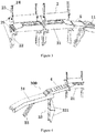
Figure 1 is a schematic diagram of an entire structure according to the present application; -
Figure 2 is a schematic structural diagram of a middle running plate assembly according to the present application; -
Figure 3 is a schematic structural diagram of an end running plate assembly according to the present application; -
Figure 4 is a schematic structural diagram of a bridge plate device according to the present application; -
Figure 5 is a schematic diagram of a non-working position state of a bridge plate device according to the present application; -
Figure 6 is a schematic diagram of a non-working position state of an end running plate assembly according to the present application; -
Figure 7 is a schematic diagram showing a loading of a first truck according to the present application; -
Figure 8 is a schematic diagram showing a loading of a second truck according to the present application; -
Figure 9 is a schematic diagram showing a loading of a third truck according to the present application; and -
Figure 10 is a schematic diagram showing a loading of a fourth truck according to the present application. - Hereinafter, the present application is described in detail in conjunction with the drawings and embodiments.
- As shown in
Figure 1 , the present application includes a running plate device mounted relatively at a middle portion between two side wall assemblies of a railway wagon. The running plate device includes a middlerunning plate device 100. Two ends of the middlerunning plate device 100 are respectively provided with an endrunning plate device 200, and an outer ends of the endrunning plate device 200 is provided with abridge plate device 300. - The middle
running plate device 100 includes multiple middle runningassemblies 1 arranged side by side. As shown inFigure 2 , each of the middlerunning plate assemblies 1 includes arectangular running plate 11 rotatably connected with an side wall assembly via anaxle seat 14. Twosupport plates 12 rotatably connected with the side wall assembly via theaxle seat 14 are arranged and spaced below the runningplate 11, and the twosupport plates 12 together support the runningplate 11, so as to maintain the runningplate 11 being placed horizontally. - The end running
plate device 200 includes multiple endrunning plate assembly 2 arranged side by side. As shown inFigure 3 , each of theend running assembly 2 includes arectangular running plate 21 rotatably connected with the side wall assembly via anaxle seat 25. Twosupport plates 22 rotatably connected with the side wall assembly via theaxle seat 25 are arranged and spaced below the runningplate 21, and the twosupport plates 22 together support the runningplate 21, so as to maintain the runningplate 21 being placed horizontally. - As shown in
Figure 4 , thebridge plate device 300 includes abridge plate 31. One end of thebridge plate 31 is connected with therunning plate 21 via aconnection plate 4, and the other end of thebridge plate 31 is rotatably connected with an underframe assembly. The bottom of the end of thebridge plate 31 close to theconnection plate 4 is provided with afoldable support mechanism 32 for placing thebridge plate device 300 in a non-working state on the underframe assembly (as shown inFigure 5 ), thereby facilitating truck being loaded and unloaded. - In the above embodiment, two end of the
running plate 11 are each provided with apneumatic rod 13 rotatably connected with the side wall assembly. Thepneumatic rod 13 can provide additional output power when the runningplate 11 is rotated. The running plate may be made of steel or aluminum alloy. Nopneumatic rod 13 may be provided when the running plate is made of aluminum alloy. - In the above embodiment, the
middle running assembly 1 located at the end portion of the middle runningplate device 100 may be arranged tiltedly, and the middle runningplate assembly 1 located at the middle portion of the middle runningplate device 100 may be arranged horizontally. In this way, a recess structure is formed in the middle runningplate device 100, thereby avoiding an interference between the truck and the middle runningplate assembly 1 during a loading and unloading. - In the above embodiment, two ends of the running
plate 21 are each provided with apneumatic rod 23, and apiston rod 231 of thepneumatic rod 23 is rotatably connected with the side wall assembly. Apressure tube 23 of thepneumatic rod 23 is connected with the runningplate 21 via aconnection member 24. In this case, when thepneumatic rod 23 extends, thepressure tube 23 may drive the runningplate 21 to rotate upwards (as shown inFigure 6 ). The runningplate 21 may be made of steel or aluminum alloy. Nopneumatic rod 23 may be provided when the runningplate 21 is made of aluminum alloy. - In the above embodiment, the bottom of the
bridge plate 31 is provided with multiplepneumatic rods 33 rotatably connected with the underframe assembly. - In the above embodiment, the
foldable support mechanism 32 includes twosupports 321 both having a right-angled triangle shape. The twosupports 321 are arranged against to each other and rotatably connected with each other. Ends of the twosupports 321 that are opposite to a joint connected to each other are respectively rotatably connected with thebridge plate 31 and the underframe assembly, thereby achieving a folding of thefoldable support mechanism 32. - In the above embodiment, a
connection plate 5 may be arranged between the end runningplate assembly 2 and the middle runningplate assembly 1. - In the above embodiment, the number of the middle running
plate assemblies 1 is ten, the number of the end runningplate assemblies 2 is eight, and fourbridge plate devices 300 are provided. - A method for loading trucks is further provided according to the present application. As shown in
Figures 7 to 10 , the method includessteps 1 to 7. - In
step 1, the runningplate 11 of each of the middle runningplate assemblies 1 is placed horizontally and thesupport plate 12 is opened to support and secure the runningplate 11, the runningplate 21 of each of the end runningplate assemblies 2 is flipped down and placed horizontally and thesupport plate 22 is opened to support and secure the runningplate 21, and each of thebridge plate devices 300 is supported with thefoldable support mechanism 32 and is connected with the runningplate 21 via theconnection plate 4. - In
step 2, afirst truck 6 is driven into the railway wagon from thebridge plate device 300 at one end of the railway wagon to thebridge plate device 300 at the other end of the railway wagon and is stopped, and then, thefirst truck 6 is secured. - In step 3, the
support plate 12 of each of the middle runningplate assemblies 1 is closed to place the runningplate 11 vertically, and thesupport plate 22 of each of the end runningplate assemblies 2 at one end of the railway wagon to place the runningplate 21 in a flip-up manner, and thefoldable support mechanism 32 of thebridge plate device 300 at one end of the railway wagon is folded and theconnection plate 4 is opened to place thebridge plate device 300 on the underframe assembly. - In
step 4, asecond truck 7 is driven into the railway wagon from the underframe assembly at one end of the railway wagon to the underframe assembly at the other end of the railway wagon and close to a position below thebridge plate device 300 where thefirst truck 6 is located, and thesecond truck 7 is secured. - In
step 5, a third truck is driven into the railway wagon from the underframe assembly at one end of the railway wagon to a position close to thesecond truck 7, and is secured. - In
step 6, the runningplate 21 of each of the end runningplate assemblies 2 close to one end of the railway wagon is flipped down to place the runningplate 21 horizontally, and thesupport plate 22 is opened to support and secure the runningplate 21. Thebridge plate device 300 close to one end of the railway wagon is supported with thefoldable support mechanism 32 and is connected with the runningplate 21 via theconnection plate 4. - In
step 7, a fourth truck 9 is driven into the railway wagon from thebridge plate device 300 over thethird truck 8 and is stopped and secured at thebridge plate device 300. - A method for unloading trucks is further provided according to the present application. The method includes
steps 1 to 6. - In
step 1, thefirst truck 6 is released and driven out of thebridge plate device 300 at the other end of the railway wagon. - In
step 2, thesupport plate 22 of each of the end runningplate assemblies 2 at the other end of the railway wagon is closed to place the runningplate 21 in a flip-up manner, thefoldable support mechanism 32 of thebridge plate device 300 at the other end of the railway wagon is folded and the connection plate is opened to place thebridge plate device 300 on the underframe assembly. - In step 3, the
second truck 7 is released and driven out of the underframe assembly at the other end of the railway wagon. - In
step 4, thethird truck 8 is released and driven out of the underframe assembly at the other end of the railway wagon. - In
step 5, the runningplate 11 of each of the middle runningplate assemblies 1 is placed horizontally and thesupport plate 12 is opened to support and secure the runningplate 11, the runningplate 21 of each of the end runningplate assemblies 2 at the other end of the railway wagon is flipped down and placed horizontally and thesupport plate 22 is opened to support and secure the runningplate 22. Thebridge plate device 300 at the other end of the railway wagon is supported with thefoldable support mechanism 32 and is connected with the runningplate 21 via theconnection plate 4. - In
step 6, the fourth truck is released and driven out of thebridge plate device 300 at the other end of the railway wagon. - The above embodiments are only for further illustrating the objectives, technical solutions and benefits of the present application in detail, and are not intended to limit the present application. Accordingly, the application is not to be seen as limited by the foregoing description, but is only limited by the scope of the appended claims.
Claims (8)
- A railway wagon for transporting trucks, comprising:a running plate device mounted relatively at a middle portion between two side wall assemblies of the railway wagon,wherein the running plate device comprises a middle running plate device (100), two ends of the middle running plate device (100) are each provided with an end running plate device (200), and an outer end of the end running plate device is provided with a bridge plate device (300);the middle running plate device (100) comprises a plurality of middle running plate assemblies (1) arranged side by side, each of the middle running plate assemblies (1) comprises a first running plate (11) rotatably connected with an side wall assembly, and at least one first support plate (12) rotatably connected with the side wall assembly is arranged below the first running plate (11);the end running plate device (200) comprises a plurality of end running plate assemblies (2) arranged side by side, each of the end running plate assemblies (200) comprises a second running plate (21) rotatably connected with the side wall assembly, and at least one second support plate (22) rotatably connected with the side wall assembly is arranged below the second running plate (21); andthe bridge plate device (300) comprises a bridge plate (31), one end of the bridge plate (31) is connected with the second running plate (21) via a connection plate (4), the other end of the bridge plate (31) is rotatably connected with an underframe assembly of the railway wagon, and a bottom portion of the end of the bridge plate (31) close to the connection plate (4) is provided with a foldable support mechanism (32).
- The railway wagon for transporting trucks according to claim 1, wherein two ends of the first running plate (11) are each provided with a first pneumatic rod (13) rotatably connected to the side wall assembly.
- The railway wagon for transporting trucks according to claim 1 or 2, wherein two ends of the second running plate (21) are each provided with a second pneumatic rod (23), a piston rod (231) of the second pneumatic rod (23) is rotatably connected to the side wall assembly, and a pressure tube (232) of the second pneumatic rod (23) is securely connected with the second running plate (21) via a connection member (24).
- The railway wagon for transporting trucks according to claim 1 or 2, wherein a bottom portion of the bridge plate (31) is provided with a plurality of third pneumatic rods (33) rotatably connected with the underframe assembly.
- The railway wagon for transporting trucks according to claim 1 or 2, wherein the middle running plate assemblies (100) located at the two ends of the middle running plate device (1) are arranged tiltedly, and the middle running plate assemblies located at the middle of the middle running plate device (1) are arranged horizontally.
- The railway wagon for transporting trucks according to claim 1 or 2, wherein the foldable support mechanism (32) comprises two supports (321) both having a right-angled triangle shape, the two supports (321) are arranged against each other and are rotatably connected with each other, and the two supports (321) are respectively rotatably connected with the bridge plate (31) and the underframe assembly.
- The railway wagon for transporting trucks according to claim 1 or 2, wherein a second connection plate (5) is arranged between the end running plate assembly (2) and the middle running plate assembly (1).
- A method for loading and unloading trucks on the railway wagon according to any one of claims 1 to 7, wherein
the method for loading the trucks comprising:step 1, placing horizontally the first running plate (11) of each of the middle running plate assemblies (1) and opening the first support plate (12) to support and secure the first running plate (11), flipping down the second running plate of each of the end running plate assemblies (2) to place the second running plate (21) horizontally and opening the second support plate (22) to support and secure the second running plate (21), supporting the bridge plate device (300) with the foldable support mechanism (32) and connecting the bridge plate device (300) with the second running plate (21) via the connection plate (4);step 2, driving a first truck (6) from the bridge plate device at one end of the railway wagon to the bridge plate device (300) at the other end of the railway wagon and stopping the first truck at the bridge plate device (300) at the other end of the railway wagon, and securing the first truck;step 3, closing the first support plate (12) of each of the middle running plate assemblies (1) to place the first running plate (11) vertically, closing the second support plate (2) of each of the end running plate assemblies (22) at one end of the railway wagon to place the second running plate (21) in a flip-up manner, and folding the foldable support mechanism (32) of the bridge plate device (300) at one end of the railway wagon and opening the connection plate (4) to place the bridge plate device (300) on the underframe assembly;step 4, driving a second truck (7) into the railway wagon from the underframe assembly at one end of the railway wagon to the underframe assembly at the other end of the railway wagon close to a position below the bridge plate device (300) where the first truck (6) is located, and securing the second truck;step 5, driving a third truck (8) into the railway wagon from the underframe assembly at one end of the railway wagon to a position close to the second truck (7), and securing the third truck (8);step 6, flipping the second running plate (21) of each of the end running plate assemblies (2) close to one end of the railway wagon down to place horizontally the second running plate (21), and opening the second support plate (22) to support and secure the second running plate (21), supporting the bridge plate device (300) close to one end of the railway wagon with the foldable support mechanism (32) and connecting the bridge plate device (300) with the second running plate (21) via the connection plate (4); andstep 7, driving a fourth truck (9) into the railway wagon from the bridge plate device (300) over the third truck (8) and stopping and securing the fourth truck (9) at the bridge plate device (300); andthe method for unloading the trucks comprising:step 1, releasing the first truck (6) and driving the first truck (6) out of the bridge plate device (300) at the other end of the railway wagon;step 2, closing the second support plate (22) of each of the end running plate assemblies (2) at the other end of the railway wagon to place the second running plate (21) in a flip-up manner, folding the foldable support mechanism (32) of the bridge plate device (300) at the other end of the railway wagon and opening the connection plate (4) to place the bridge plate device (300) on the underframe assembly;step 3, releasing the second truck (7) and driving the second truck from the underframe assembly at the other end of the railway wagon;step 4, releasing the third truck (8) and driving the third truck from the underframe assembly at the other end of the railway wagon;step 5, placing horizontally the first running plate (11) of each of the middle running plate assemblies (1) and opening the first support plate (12) to support the first running plate (11), flipping down the second running plate (21) of each of the end running plate assemblies (2) at the other end of the railway wagon to place the second running plate (21) horizontally and opening the second support plate (22) to support and secure the second running plate (21), supporting the bridge plate device (300) at the other end of the railway wagon with the foldable support mechanism (32) and connecting the bridge plate device (300) with the second running plate (21) via the connection plate (4); andstep 6, releasing the fourth truck (9) and driving the fourth truck (9) out of the bridge plate device (300) at the other end of the railway wagon.
Applications Claiming Priority (2)
| Application Number | Priority Date | Filing Date | Title |
|---|---|---|---|
| CN201510954098.9A CN105480236B (en) | 2015-12-17 | 2015-12-17 | The railway freight-car and truck handling method of a kind of haulage truck |
| PCT/CN2016/108327 WO2017101683A1 (en) | 2015-12-17 | 2016-12-02 | Railway wagon for transporting trucks and method for loading and unloading truck |
Publications (3)
| Publication Number | Publication Date |
|---|---|
| EP3392113A1 EP3392113A1 (en) | 2018-10-24 |
| EP3392113A4 EP3392113A4 (en) | 2019-09-04 |
| EP3392113B1 true EP3392113B1 (en) | 2020-11-11 |
Family
ID=55667611
Family Applications (1)
| Application Number | Title | Priority Date | Filing Date |
|---|---|---|---|
| EP16874740.0A Active EP3392113B1 (en) | 2015-12-17 | 2016-12-02 | Railway wagon for transporting trucks and method for loading and unloading truck |
Country Status (4)
| Country | Link |
|---|---|
| US (1) | US10569789B2 (en) |
| EP (1) | EP3392113B1 (en) |
| CN (1) | CN105480236B (en) |
| WO (1) | WO2017101683A1 (en) |
Families Citing this family (1)
| Publication number | Priority date | Publication date | Assignee | Title |
|---|---|---|---|---|
| CN105480236B (en) * | 2015-12-17 | 2017-10-03 | 南车二七车辆有限公司 | The railway freight-car and truck handling method of a kind of haulage truck |
Family Cites Families (18)
| Publication number | Priority date | Publication date | Assignee | Title |
|---|---|---|---|---|
| US1862938A (en) * | 1930-04-04 | 1932-06-14 | Sullivan Machinery Co | Transport truck |
| US2452270A (en) * | 1945-03-05 | 1948-10-26 | Traffic Transp Engineering Inc | Trailer |
| FR2269434B1 (en) | 1974-04-30 | 1976-12-17 | Venissieux Atel | |
| JPH01269662A (en) * | 1988-04-20 | 1989-10-27 | Metsukusu:Kk | Self-traveling transport device for trunk for transporting ballast |
| US5032044A (en) | 1990-04-24 | 1991-07-16 | Southern Pacific Transportation Company | Light weight stowable front wheel seats for hauling large semistacked highway trucks in railroad cars of extraordinary height |
| DE4304635A1 (en) * | 1993-02-16 | 1994-08-18 | Fmb Fahrzeug Und Maschinenbau | Low-level transporter railway waggon of a special design |
| FR2778880B1 (en) * | 1998-05-20 | 2000-07-21 | Lohr Ind | REAR SUPPORT AND POSITIONING STRUCTURE FOR A CAR TRANSPORT VEHICLE |
| US7255047B1 (en) * | 2000-08-29 | 2007-08-14 | National Steel Car Limited | Vehicle carrying rail road car and bridge plate therefor |
| US6551039B1 (en) * | 2000-09-11 | 2003-04-22 | National Steel Car Limited | Auto rack rail road car with reduced slack |
| DE10104005A1 (en) * | 2001-01-31 | 2002-08-01 | Werner Haag | Method and low-floor vehicle for transporting road vehicles by rail |
| US7575402B2 (en) * | 2006-07-06 | 2009-08-18 | Toyota Motor Credit Corporation | Vehicle transporter with screw actuators |
| CN102395501B (en) * | 2009-04-16 | 2014-09-24 | K科技有限公司 | Railway wagon and a method of its loading |
| CN201538319U (en) * | 2009-11-06 | 2010-08-04 | 南车二七车辆有限公司 | Movable platform for railway transportation vehicle |
| CN201559658U (en) * | 2009-11-06 | 2010-08-25 | 南车二七车辆有限公司 | Railway transport vehicle turning mobile stage |
| CN104386075B (en) * | 2014-11-12 | 2017-05-24 | 南车二七车辆有限公司 | Wagon for transporting commercial trucks and loading method for wagon |
| CN204323346U (en) * | 2014-11-28 | 2015-05-13 | 齐齐哈尔轨道交通装备有限责任公司 | Railway truck and shipping loading and unloading system |
| CN105480236B (en) * | 2015-12-17 | 2017-10-03 | 南车二七车辆有限公司 | The railway freight-car and truck handling method of a kind of haulage truck |
| CN205327063U (en) * | 2015-12-17 | 2016-06-22 | 南车二七车辆有限公司 | Railway freight car for transporting truck |
-
2015
- 2015-12-17 CN CN201510954098.9A patent/CN105480236B/en active Active
-
2016
- 2016-12-02 WO PCT/CN2016/108327 patent/WO2017101683A1/en active Application Filing
- 2016-12-02 EP EP16874740.0A patent/EP3392113B1/en active Active
- 2016-12-02 US US16/062,322 patent/US10569789B2/en active Active
Non-Patent Citations (1)
| Title |
|---|
| None * |
Also Published As
| Publication number | Publication date |
|---|---|
| EP3392113A1 (en) | 2018-10-24 |
| WO2017101683A1 (en) | 2017-06-22 |
| CN105480236B (en) | 2017-10-03 |
| US10569789B2 (en) | 2020-02-25 |
| US20180370548A1 (en) | 2018-12-27 |
| CN105480236A (en) | 2016-04-13 |
| EP3392113A4 (en) | 2019-09-04 |
Similar Documents
| Publication | Publication Date | Title |
|---|---|---|
| US8342784B2 (en) | Collapsible intermodal transport platform | |
| US8757943B2 (en) | Intermodal transport platform | |
| CN206384597U (en) | Transport vehicle frame | |
| CN110001695B (en) | Railway piggyback transport vehicle and underframe thereof | |
| JP3724588B2 (en) | Body with superstructure | |
| CN101715401B (en) | Railroad well car with open truss sides | |
| CN203780625U (en) | Hydraulictelescopic load transportation carriage | |
| CN209833631U (en) | Railway piggyback transport vehicle and underframe thereof | |
| CN110884513A (en) | Piggyback transport vehicle | |
| CN202703597U (en) | Rail wagon split turnover type wagon roof structure | |
| CN111032473B (en) | Universal system for transporting removable freight modules | |
| EP3392113B1 (en) | Railway wagon for transporting trucks and method for loading and unloading truck | |
| CN205396095U (en) | Carry transportation of out -of --way formula on back and use novel railway freight car | |
| CN205652129U (en) | Carry transportation of out -of --way formula on back and use novel railway freight car | |
| RU160202U1 (en) | DEVICE FOR FASTENING CARGO ON VEHICLE | |
| BE1012968A3 (en) | Versatile trailer for transportation of freight cars or road and / or rail. | |
| KR100784781B1 (en) | Transporter for easily maintenance | |
| CN205327063U (en) | Railway freight car for transporting truck | |
| CN105966473A (en) | Truck with replaceable wagon box | |
| CN201172431Y (en) | Self-dumping box | |
| CN110509943A (en) | Vehicle frame and flatcar | |
| CN104802811A (en) | Special transport vehicle for both cars and containers | |
| CN111301454B (en) | Wagon body for railway wagon and railway wagon | |
| CN212243108U (en) | Trailer lower floor platform | |
| CN211391061U (en) | Liftable load freight train |
Legal Events
| Date | Code | Title | Description |
|---|---|---|---|
| STAA | Information on the status of an ep patent application or granted ep patent |
Free format text: STATUS: THE INTERNATIONAL PUBLICATION HAS BEEN MADE |
|
| PUAI | Public reference made under article 153(3) epc to a published international application that has entered the european phase |
Free format text: ORIGINAL CODE: 0009012 |
|
| STAA | Information on the status of an ep patent application or granted ep patent |
Free format text: STATUS: REQUEST FOR EXAMINATION WAS MADE |
|
| 17P | Request for examination filed |
Effective date: 20180621 |
|
| AK | Designated contracting states |
Kind code of ref document: A1 Designated state(s): AL AT BE BG CH CY CZ DE DK EE ES FI FR GB GR HR HU IE IS IT LI LT LU LV MC MK MT NL NO PL PT RO RS SE SI SK SM TR |
|
| AX | Request for extension of the european patent |
Extension state: BA ME |
|
| DAV | Request for validation of the european patent (deleted) | ||
| DAX | Request for extension of the european patent (deleted) | ||
| A4 | Supplementary search report drawn up and despatched |
Effective date: 20190807 |
|
| RIC1 | Information provided on ipc code assigned before grant |
Ipc: B61D 47/00 20060101ALI20190801BHEP Ipc: B61D 3/18 20060101AFI20190801BHEP |
|
| GRAP | Despatch of communication of intention to grant a patent |
Free format text: ORIGINAL CODE: EPIDOSNIGR1 |
|
| STAA | Information on the status of an ep patent application or granted ep patent |
Free format text: STATUS: GRANT OF PATENT IS INTENDED |
|
| INTG | Intention to grant announced |
Effective date: 20200625 |
|
| GRAS | Grant fee paid |
Free format text: ORIGINAL CODE: EPIDOSNIGR3 |
|
| GRAA | (expected) grant |
Free format text: ORIGINAL CODE: 0009210 |
|
| STAA | Information on the status of an ep patent application or granted ep patent |
Free format text: STATUS: THE PATENT HAS BEEN GRANTED |
|
| AK | Designated contracting states |
Kind code of ref document: B1 Designated state(s): AL AT BE BG CH CY CZ DE DK EE ES FI FR GB GR HR HU IE IS IT LI LT LU LV MC MK MT NL NO PL PT RO RS SE SI SK SM TR |
|
| REG | Reference to a national code |
Ref country code: GB Ref legal event code: FG4D |
|
| REG | Reference to a national code |
Ref country code: CH Ref legal event code: EP |
|
| REG | Reference to a national code |
Ref country code: AT Ref legal event code: REF Ref document number: 1333188 Country of ref document: AT Kind code of ref document: T Effective date: 20201115 |
|
| REG | Reference to a national code |
Ref country code: DE Ref legal event code: R096 Ref document number: 602016047863 Country of ref document: DE |
|
| REG | Reference to a national code |
Ref country code: IE Ref legal event code: FG4D |
|
| REG | Reference to a national code |
Ref country code: NL Ref legal event code: MP Effective date: 20201111 |
|
| REG | Reference to a national code |
Ref country code: AT Ref legal event code: MK05 Ref document number: 1333188 Country of ref document: AT Kind code of ref document: T Effective date: 20201111 |
|
| PG25 | Lapsed in a contracting state [announced via postgrant information from national office to epo] |
Ref country code: RS Free format text: LAPSE BECAUSE OF FAILURE TO SUBMIT A TRANSLATION OF THE DESCRIPTION OR TO PAY THE FEE WITHIN THE PRESCRIBED TIME-LIMIT Effective date: 20201111 Ref country code: PT Free format text: LAPSE BECAUSE OF FAILURE TO SUBMIT A TRANSLATION OF THE DESCRIPTION OR TO PAY THE FEE WITHIN THE PRESCRIBED TIME-LIMIT Effective date: 20210311 Ref country code: NO Free format text: LAPSE BECAUSE OF FAILURE TO SUBMIT A TRANSLATION OF THE DESCRIPTION OR TO PAY THE FEE WITHIN THE PRESCRIBED TIME-LIMIT Effective date: 20210211 Ref country code: GR Free format text: LAPSE BECAUSE OF FAILURE TO SUBMIT A TRANSLATION OF THE DESCRIPTION OR TO PAY THE FEE WITHIN THE PRESCRIBED TIME-LIMIT Effective date: 20210212 Ref country code: FI Free format text: LAPSE BECAUSE OF FAILURE TO SUBMIT A TRANSLATION OF THE DESCRIPTION OR TO PAY THE FEE WITHIN THE PRESCRIBED TIME-LIMIT Effective date: 20201111 |
|
| PG25 | Lapsed in a contracting state [announced via postgrant information from national office to epo] |
Ref country code: SE Free format text: LAPSE BECAUSE OF FAILURE TO SUBMIT A TRANSLATION OF THE DESCRIPTION OR TO PAY THE FEE WITHIN THE PRESCRIBED TIME-LIMIT Effective date: 20201111 Ref country code: IS Free format text: LAPSE BECAUSE OF FAILURE TO SUBMIT A TRANSLATION OF THE DESCRIPTION OR TO PAY THE FEE WITHIN THE PRESCRIBED TIME-LIMIT Effective date: 20210311 Ref country code: PL Free format text: LAPSE BECAUSE OF FAILURE TO SUBMIT A TRANSLATION OF THE DESCRIPTION OR TO PAY THE FEE WITHIN THE PRESCRIBED TIME-LIMIT Effective date: 20201111 Ref country code: LV Free format text: LAPSE BECAUSE OF FAILURE TO SUBMIT A TRANSLATION OF THE DESCRIPTION OR TO PAY THE FEE WITHIN THE PRESCRIBED TIME-LIMIT Effective date: 20201111 Ref country code: BG Free format text: LAPSE BECAUSE OF FAILURE TO SUBMIT A TRANSLATION OF THE DESCRIPTION OR TO PAY THE FEE WITHIN THE PRESCRIBED TIME-LIMIT Effective date: 20210211 Ref country code: AT Free format text: LAPSE BECAUSE OF FAILURE TO SUBMIT A TRANSLATION OF THE DESCRIPTION OR TO PAY THE FEE WITHIN THE PRESCRIBED TIME-LIMIT Effective date: 20201111 |
|
| REG | Reference to a national code |
Ref country code: LT Ref legal event code: MG9D |
|
| PG25 | Lapsed in a contracting state [announced via postgrant information from national office to epo] |
Ref country code: HR Free format text: LAPSE BECAUSE OF FAILURE TO SUBMIT A TRANSLATION OF THE DESCRIPTION OR TO PAY THE FEE WITHIN THE PRESCRIBED TIME-LIMIT Effective date: 20201111 |
|
| REG | Reference to a national code |
Ref country code: DE Ref legal event code: R119 Ref document number: 602016047863 Country of ref document: DE |
|
| PG25 | Lapsed in a contracting state [announced via postgrant information from national office to epo] |
Ref country code: SK Free format text: LAPSE BECAUSE OF FAILURE TO SUBMIT A TRANSLATION OF THE DESCRIPTION OR TO PAY THE FEE WITHIN THE PRESCRIBED TIME-LIMIT Effective date: 20201111 Ref country code: RO Free format text: LAPSE BECAUSE OF FAILURE TO SUBMIT A TRANSLATION OF THE DESCRIPTION OR TO PAY THE FEE WITHIN THE PRESCRIBED TIME-LIMIT Effective date: 20201111 Ref country code: EE Free format text: LAPSE BECAUSE OF FAILURE TO SUBMIT A TRANSLATION OF THE DESCRIPTION OR TO PAY THE FEE WITHIN THE PRESCRIBED TIME-LIMIT Effective date: 20201111 Ref country code: SM Free format text: LAPSE BECAUSE OF FAILURE TO SUBMIT A TRANSLATION OF THE DESCRIPTION OR TO PAY THE FEE WITHIN THE PRESCRIBED TIME-LIMIT Effective date: 20201111 Ref country code: LT Free format text: LAPSE BECAUSE OF FAILURE TO SUBMIT A TRANSLATION OF THE DESCRIPTION OR TO PAY THE FEE WITHIN THE PRESCRIBED TIME-LIMIT Effective date: 20201111 |
|
| REG | Reference to a national code |
Ref country code: CH Ref legal event code: PL |
|
| PG25 | Lapsed in a contracting state [announced via postgrant information from national office to epo] |
Ref country code: DK Free format text: LAPSE BECAUSE OF FAILURE TO SUBMIT A TRANSLATION OF THE DESCRIPTION OR TO PAY THE FEE WITHIN THE PRESCRIBED TIME-LIMIT Effective date: 20201111 Ref country code: MC Free format text: LAPSE BECAUSE OF FAILURE TO SUBMIT A TRANSLATION OF THE DESCRIPTION OR TO PAY THE FEE WITHIN THE PRESCRIBED TIME-LIMIT Effective date: 20201111 |
|
| REG | Reference to a national code |
Ref country code: BE Ref legal event code: MM Effective date: 20201231 |
|
| PLBE | No opposition filed within time limit |
Free format text: ORIGINAL CODE: 0009261 |
|
| STAA | Information on the status of an ep patent application or granted ep patent |
Free format text: STATUS: NO OPPOSITION FILED WITHIN TIME LIMIT |
|
| 26N | No opposition filed |
Effective date: 20210812 |
|
| GBPC | Gb: european patent ceased through non-payment of renewal fee |
Effective date: 20210211 |
|
| PG25 | Lapsed in a contracting state [announced via postgrant information from national office to epo] |
Ref country code: NL Free format text: LAPSE BECAUSE OF FAILURE TO SUBMIT A TRANSLATION OF THE DESCRIPTION OR TO PAY THE FEE WITHIN THE PRESCRIBED TIME-LIMIT Effective date: 20201111 Ref country code: IE Free format text: LAPSE BECAUSE OF NON-PAYMENT OF DUE FEES Effective date: 20201202 Ref country code: AL Free format text: LAPSE BECAUSE OF FAILURE TO SUBMIT A TRANSLATION OF THE DESCRIPTION OR TO PAY THE FEE WITHIN THE PRESCRIBED TIME-LIMIT Effective date: 20201111 Ref country code: LU Free format text: LAPSE BECAUSE OF NON-PAYMENT OF DUE FEES Effective date: 20201202 Ref country code: IT Free format text: LAPSE BECAUSE OF FAILURE TO SUBMIT A TRANSLATION OF THE DESCRIPTION OR TO PAY THE FEE WITHIN THE PRESCRIBED TIME-LIMIT Effective date: 20201111 |
|
| PG25 | Lapsed in a contracting state [announced via postgrant information from national office to epo] |
Ref country code: LI Free format text: LAPSE BECAUSE OF NON-PAYMENT OF DUE FEES Effective date: 20201231 Ref country code: SI Free format text: LAPSE BECAUSE OF FAILURE TO SUBMIT A TRANSLATION OF THE DESCRIPTION OR TO PAY THE FEE WITHIN THE PRESCRIBED TIME-LIMIT Effective date: 20201111 Ref country code: DE Free format text: LAPSE BECAUSE OF NON-PAYMENT OF DUE FEES Effective date: 20210701 Ref country code: CH Free format text: LAPSE BECAUSE OF NON-PAYMENT OF DUE FEES Effective date: 20201231 |
|
| PG25 | Lapsed in a contracting state [announced via postgrant information from national office to epo] |
Ref country code: GB Free format text: LAPSE BECAUSE OF NON-PAYMENT OF DUE FEES Effective date: 20210211 Ref country code: ES Free format text: LAPSE BECAUSE OF FAILURE TO SUBMIT A TRANSLATION OF THE DESCRIPTION OR TO PAY THE FEE WITHIN THE PRESCRIBED TIME-LIMIT Effective date: 20201111 |
|
| PG25 | Lapsed in a contracting state [announced via postgrant information from national office to epo] |
Ref country code: IS Free format text: LAPSE BECAUSE OF FAILURE TO SUBMIT A TRANSLATION OF THE DESCRIPTION OR TO PAY THE FEE WITHIN THE PRESCRIBED TIME-LIMIT Effective date: 20210311 Ref country code: MT Free format text: LAPSE BECAUSE OF FAILURE TO SUBMIT A TRANSLATION OF THE DESCRIPTION OR TO PAY THE FEE WITHIN THE PRESCRIBED TIME-LIMIT Effective date: 20201111 Ref country code: CY Free format text: LAPSE BECAUSE OF FAILURE TO SUBMIT A TRANSLATION OF THE DESCRIPTION OR TO PAY THE FEE WITHIN THE PRESCRIBED TIME-LIMIT Effective date: 20201111 |
|
| PG25 | Lapsed in a contracting state [announced via postgrant information from national office to epo] |
Ref country code: MK Free format text: LAPSE BECAUSE OF FAILURE TO SUBMIT A TRANSLATION OF THE DESCRIPTION OR TO PAY THE FEE WITHIN THE PRESCRIBED TIME-LIMIT Effective date: 20201111 |
|
| PG25 | Lapsed in a contracting state [announced via postgrant information from national office to epo] |
Ref country code: BE Free format text: LAPSE BECAUSE OF NON-PAYMENT OF DUE FEES Effective date: 20201231 |
|
| PGFP | Annual fee paid to national office [announced via postgrant information from national office to epo] |
Ref country code: TR Payment date: 20231019 Year of fee payment: 8 Ref country code: FR Payment date: 20231219 Year of fee payment: 8 Ref country code: CZ Payment date: 20231020 Year of fee payment: 8 |