EP3391341B1 - Streak artifact prediction - Google Patents
Streak artifact prediction Download PDFInfo
- Publication number
- EP3391341B1 EP3391341B1 EP16822630.6A EP16822630A EP3391341B1 EP 3391341 B1 EP3391341 B1 EP 3391341B1 EP 16822630 A EP16822630 A EP 16822630A EP 3391341 B1 EP3391341 B1 EP 3391341B1
- Authority
- EP
- European Patent Office
- Prior art keywords
- image
- imaging
- projection
- rotation plane
- reconstruction
- Prior art date
- Legal status (The legal status is an assumption and is not a legal conclusion. Google has not performed a legal analysis and makes no representation as to the accuracy of the status listed.)
- Active
Links
Images


Classifications
-
- G—PHYSICS
- G06—COMPUTING OR CALCULATING; COUNTING
- G06T—IMAGE DATA PROCESSING OR GENERATION, IN GENERAL
- G06T11/00—2D [Two Dimensional] image generation
- G06T11/003—Reconstruction from projections, e.g. tomography
- G06T11/005—Specific pre-processing for tomographic reconstruction, e.g. calibration, source positioning, rebinning, scatter correction, retrospective gating
-
- A—HUMAN NECESSITIES
- A61—MEDICAL OR VETERINARY SCIENCE; HYGIENE
- A61B—DIAGNOSIS; SURGERY; IDENTIFICATION
- A61B5/00—Measuring for diagnostic purposes; Identification of persons
- A61B5/74—Details of notification to user or communication with user or patient; User input means
- A61B5/742—Details of notification to user or communication with user or patient; User input means using visual displays
-
- A—HUMAN NECESSITIES
- A61—MEDICAL OR VETERINARY SCIENCE; HYGIENE
- A61B—DIAGNOSIS; SURGERY; IDENTIFICATION
- A61B6/00—Apparatus or devices for radiation diagnosis; Apparatus or devices for radiation diagnosis combined with radiation therapy equipment
- A61B6/02—Arrangements for diagnosis sequentially in different planes; Stereoscopic radiation diagnosis
- A61B6/03—Computed tomography [CT]
- A61B6/032—Transmission computed tomography [CT]
-
- A—HUMAN NECESSITIES
- A61—MEDICAL OR VETERINARY SCIENCE; HYGIENE
- A61B—DIAGNOSIS; SURGERY; IDENTIFICATION
- A61B6/00—Apparatus or devices for radiation diagnosis; Apparatus or devices for radiation diagnosis combined with radiation therapy equipment
- A61B6/40—Arrangements for generating radiation specially adapted for radiation diagnosis
- A61B6/4064—Arrangements for generating radiation specially adapted for radiation diagnosis specially adapted for producing a particular type of beam
- A61B6/4085—Cone-beams
-
- G—PHYSICS
- G06—COMPUTING OR CALCULATING; COUNTING
- G06T—IMAGE DATA PROCESSING OR GENERATION, IN GENERAL
- G06T11/00—2D [Two Dimensional] image generation
- G06T11/003—Reconstruction from projections, e.g. tomography
- G06T11/008—Specific post-processing after tomographic reconstruction, e.g. voxelisation, metal artifact correction
Definitions
- the invention relates to an image processing system, to an imaging arrangement, to an image processing method, to a computer program element, and to a computer readable medium.
- a highly radiopaque object e.g. a metal object
- a highly radiopaque object e.g. a metal object
- streak artifacts can obscure clinically relevant information.
- interventional (stent-assisted) coiling procedures after a (metallic) coil has been placed to treat aneurysms, the metal coil may cause severe streak artifacts in a reconstructed cone-beam CT (CBCT) image, potentially obscuring clinically relevant details, e.g., the stent-vessel wall interface.
- CBCT cone-beam CT
- CN103617598 is a kind of CT image metal artifacts removal method; forward projection obtains the projected footprint of each high density tissue pixels; and then to having overlapping interval to repair with other high density tissues on track, all high density tissue pixels points are repeated to above repair process, the sinogram that obtains finally repairing.
- WO2010038195 relates to a method and a system for removing butting or stitching artifacts from images, in particular from x-ray images from scanning x-ray systems.
- an image processing system comprising:
- an impact (extent and/or orientation) of the artifact relative to a region of interest (ROI) in a reconstruction is evaluated before doing a full rotational CBCT scan, thus avoiding unnecessary X-ray dosage.
- This allows avoiding imaging geometries that would result in reconstructions that are potentially useless as the ROI may turn out to be too severely compromised by the artifacts.
- the proposed system allows simulating or trying different imaging geometry settings, without radiation exposure, until an imaging geometry is found which would result in a reconstruction where the ROI is less, or not at all,affected by the artifact(s). Based on the image processing, the system allows a user or a protocol to control the imaging geometry and use an alternative imaging trajectory.
- a possible adjustment of said spatial configuration may be realized by defining an adjusted rotation plane having a different rotation axis than the current (first) rotation plane.
- an adjustment of a rotational plane, in which a CBCT rotational scan will be carried out, with respect to the object to be imaged may be determined.
- a tilt angle of the rotational plane may be increased or decreased so that a reconstruction from images of a CBCT scan to be carried out along a trajectory in the adjusted rotational plane would exhibit reduced image artefacts in the region of interest.
- the increasing or decreasing of the tilt angle may be determined automatically, for example image artefacts for a number of different adjusted rotational planes may be simulated and used to find a minimum in the intersection between their projection and the region of interest.
- the system is provided with a visualizer configured to provide, to a display unit, image information representing the input image together with a visual indication of the projection area of the reconstruction artefact.
- the visualizer may also, in addition, display a visual indication of the projection area of the reconstruction artefact for one or more adjusted spatial configurations.
- a user may be enabled to try out various spatial configurations to find one in which reconstruction artefacts will be substantially reduced.
- said reconstruction artifact is caused by a radio-opaque object, in particular a metal object, resident in the imaging region.
- said specified change of the spatial configuration is effectuated by a human user.
- a graphical user interface is provided that is configured to allow the user to graphically specify an adjustment of the relative spatial configuration between the object and the rotation plane.
- the user may use the visual indication of the projection area of the reconstruction artefact and its intersection with the region of interest, as provided by the visualizer, as a guidance.
- an imaging arrangement that comprises the image processing system as per any one above mentioned embodiments and said imaging apparatus and/or said display unit.
- an image processing method comprising:
- the predicting and determining step are repeated, with the aim of decreasing an image area of the intersection between the projection of the reconstruction artefact and the region of interest in an iterative process.
- the steps may be repeated automatically until no artefact projection intersecting with the region of interest remains, or at least until a minimum size for the intersection area has been found if that proves to be not possible.
- the method comprises operating the imaging apparatus to acquire projection images at different positions on the trajectory in accordance with the adjusted relative spatial configuration between the rotation plane and the object.
- a rotational CBCT image acquisition scan may be carried out.
- a volumetric image of at least the region of interest may be reconstructed.
- a reconstruction based on the projection images will yield volumetric imagery wherein the ROI is either not compromised at all by reconstruction artifact or is at least compromised up to a more acceptable level.
- the new imaging geometry is selected so that any collision between C-arm, patient and table may be avoided.
- the selected trajectory may not reflect an absolute minimum in reconstruction artefacts interfering with the region of interest, but rather a relative minimum within the constraint of a collision-free movement of the imaging system being required.
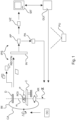
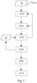
- FIG. 1 there is shown a schematic block diagram of an imaging arrangement including an imaging apparatus IM and an image processing system IPS.
- the left part of the Figure shows a rotational imaging apparatus IM such as a C-arm system or alternatively a CT scanner.
- the right part of Figure 1 shows modules and related circuitry of the image processing system IPS.
- the image processing system IPS allows manual or automatic operation of the imaging apparatus IM so as to reduce effects of streak artifacts in imagery reconstructed from projection data acquired by the imaging apparatus IM.
- this includes an X-ray source XR and a detector D.
- Being a rotational X-ray system it is at least the X-ray source XR that is rotatable in a trajectory around an imaging region.
- the (rotation) plane of the trajectory is shown in Figure 1 as a dashed line as said plane is understood to extend into the paper plane of the drawing.
- the trajectory may not necessarily be circular although this will be the case indeed in some preferred embodiments.
- the X-ray source orbits in a complete rotation around the imaging region. Indeed in some embodiments the trajectory defines only a partial arc such as 200° around the imaging region.
- the detector and the X-ray source that are arranged opposite each other whilst both rotate around the imaging region tracing out the imaging trajectory.
- the detector is arranged as a stationery circular arrangement around the imaging region.
- an object or patient P human or animal
- a suitable support C such as a couch.
- the imaging set-up is so arranged that the region of interest ROI is situated in the iso-center of the imaging trajectory.
- the imaged object P may be a human or animal patient or a particular part thereof.
- a series of projection images are acquired whilst the X-ray source traces out the trajectory around the imaging region and hence around the region of interest.
- cone beam CT particularly envisaged herein, a relatively large number (such as 600 or more) projection images are acquired.
- the projection images can then be processed by a re-constructer component RECON.
- the re-constructer component RECON implements a reconstruction algorithm such as filtered back-projection or otherwise (such as iterative methods) to produce the cross sectional image.
- an orientation of the rotation plane ⁇ can be adjusted. More particularly a spatial configuration (also referred to herein as "imaging geometry") between the rotation plane and the object (and hence the ROI) can be changed. Yet more precisely and geometrically speaking, it is the rotation axis ⁇ of the rotation plane ⁇ that can be altered by operation of one or more suitable actuators.
- the actuators e.g., stepper motors etc.
- the spatial configuration between the rotation plane and the object P can also be changed by shifting or rotating the support C on which the object is deposed.
- the change of the spatial configuration between the rotation plane and the object can be requested from an operator console OC.
- the user can operate a joy-stick or other input device to effect suitable adjustments of the imaging geometry.
- the change of imaging geometry is requested automatically by an imaging protocol.
- Figure 1 the degrees of spatial freedom are shown at the example of a C-arm imager.
- the rotation of the X-ray source XR in rotation plane ⁇ around the imaging region and axis ⁇ is shown in Figure 1 .
- the rotation axis ⁇ runs parallel to the plane of the drawing with the rotation plane ⁇ extending into the drawing plane.
- One possible way to change the rotation axis ⁇ is to rotate same out of the drawing plane, thereby defining a new rotation plane ⁇ ' (not shown).
- This process entails assigning individual image values to the respective voxel positions to so build up the distribution und thus the cross sectional image in a given plane.
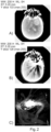
- the violation of the underlying assumptions in respect of the spectrum together with the photon starvation may cause the reconstruction algorithm to return an artificial material distribution that does not correctly describe the true material distribution thus producing streak artifacts that have a hedgehog-like appearance as shown in panes B),C) in the exemplary imagery in Figure 2 .
- the radiation opaque objects The exemplary streak artifacts as shown in B), C) in Figure 2 can obscure clinically relevant information.
- the CT reconstruction in pane A) represents a situation where no artifacts are present.
- pane B shows another streak artifact in reconstructed imagery where a part of a stent is obscured by streaks caused by an implanted metal coil.
- the proposed imaging processing system IPS is configured to indicate areas that are potentially affected by streak artifacts in a single (or a few) input projection image, prior to acquiring all the projection images necessary for reconstruction.
- a scout image may be used as the input image for indicting therein the artifact affected area(s).
- the user can then reposition the patient and/or plan a different trajectory to avoid having artifacts in critical areas of interest.
- the remaining projection images can be acquired and they are then passed on to the reconstructor RECON to perform the reconstruction. In this way, the chances that important information is obscured by artifacts are considerably lower. This can lead to i) less radiation dose for the patient, since scans do not need to be retaken and ii) better diagnosis, since critical information is not obscured by streak artifacts.
- the (one or more) input projection image is received at input port IN.
- This input image may be a single projection image or maybe formed from a more than one projection images that are required with the X-ray imaging apparatus IM.
- the input image is then analyzed by an image artifact extent predictor AP.
- Predictor AP is configured to predict in the input image a projection area of an artifact as it would appear in a reconstruction if one were to reconstruct from projection images using the rotation plane as per the current input image.
- this prediction is based on an identification of the footprint of radiation-opaque objects obtained in a segmentation. Since the intended trajectory of the rotational image acquisition in respect of the X-ray image is known, an orientation and/or extent of a streak artifacts caused by the radio opaque object in a reconstruction can be predicted.
- this information can be output on a monitor MT as a visual feedback via visualizer VIZ.
- a visual indicator for said area can be overlaid on the input X-ray image.
- CBCT is advantageous over fan beam CT, as the projection image in CBCT is a 2D radiograph which can be rendered directly for view with the indicator overlaid.
- Figure 3 shows a visual output according to one embodiment as produced by the visualizer VIZ.
- the visual indicator VI indicates the predicted projection area affected by streak artifacts caused by the highly radio-opaque object.
- the image shown by the visualizer VIZ enables a user to identify an area of intersection between the artefact projection and a region of interest as guidance in selecting a potential adjustment for the spatial configuration.
- a graphical user interface GUI may be provided in which the user can select different orientations or inclinations for the rotation plane and thereby determine the adjusted spatial configuration
- the predictor AP and the visualizer VIZ may then co-operate to update the visual indicator in the input image accordingly and the visual indication then shows the intersection area between the region of interest and a projection of a reconstruction artefact as it would appear if the newly specified rotation plane were to be used for the acquisition of projection images.
- the updated or adapted visual indictor may be displayed together with the current image or a new projection image in the newly specified imaging geometry can be acquired and the adapted visual indicator is displayed together with the newly acquired image.
- An imaging geometry adjuster PA is configured to determine an adjustment for instance of the orientation, direction or tilt of the rotation plane so that the disturbance by the streak artifact on the pre-defined region of interest is mitigated or reduced. More particularly, a geometrical intersection between the predicted projection area and the area that corresponds to the region of interest is decreased, when the adjusted imaging geometry is selected and effectuated.
- the adjuster PA may carry out a simulated determination of one or more adjusted imaging geometries, and subsequently also control a physically adjustment of one or more system components so as to effectuate an actual adjustment of the imaging geometry.
- the predictor AP may then determine an updated projection area of a reconstruction artefact in a simulated adjusted spatial configuration. The prediction and adjustment determination may be repeated until a desirable geometry has been found.
- a physical movement of components of an imaging system is only required once a desirable imaging geometry, for example a rotation plane in which reconstruction artefacts in the region of interest will be reduced, has been identified.
- the above introduced components such as an input port, the visualizer, the adjuster and the graphical user interface can be implemented as functional modules that are run as software routines on a data processing unit PU such as a general purpose computer.
- the software routine may run on a work station associated with the imager IM or with a group of imagers in a network.
- Implementations of the components other than in software are also envisaged and include field programmable field arrays (FPGA) or integrated circuits (IC) or others.
- the visual indication shown in Figure 3 of the projection area has roughly the shape of a lozenge or diamond. This shape is a consequence of the manner of which the projection area is computed as will be explained further below with reference to Figures 4 and 5 .
- Other shapes of the visual indicator however are also envisaged herein.
- the visual indicator VI for the projection area has a directional component to be able to intuitively indicate to the user a main orientation or main direction of the streak artifacts.
- the footprint of the radiation-opaque element may also be indicated graphically such as a circle as shown in the Figure 3 but other shapes are also envisaged.
- the visual indicator in one embodiment has a compass needle appearance.
- the visual indication VI may be rendered as color-coded to better offset against the background.
- the visual indicator VI merely outlines contours of the streak artifact affected area to minimize obstruction of underlying image information.
- the segmentation of the high opacity object may itself be color coded in a different color from the one used for the symbology that is indicative of the projection area.
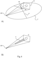
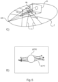
- Figures 4 and 5 are illustrations of the operation of the projection area predictor AP.
- Figure 4 or 5 are illustrations of the underlying algorithmic steps for computing shape and/or extent of the predicted artifact inflicted projection area.
- the X-ray geometry determines a trajectory traced out during the projection image acquisition. For simplicity, let's assume this trajectory is circular.
- a virtual line can be defined from a focal spot of the X-ray source XR to the detector's D center. When this line is followed during the circular trajectory, a virtual disk in the rotation plane is defined.
- the virtual disk can be projected as a line on the X-ray projection image (such as one acquired by a CBCT).
- This line defines the main orientation of the streak artifacts that would be caused by the radiopaque object in a reconstruction. And it is the course of this line relative to the ROI in the image that can be changed by changing the imaging geometry, e.g. changing the rotation plane or changing the position/tilt of the patient support C.
- FIG 4A shows an illustration of the rotation plane now shown for ease of representation horizontally rather than vertically.
- the radiation can be thought of as propagating along rays r that emanate from the focal spot towards the detector at the given position on the trajectory.
- the rays form respective cones in the surrounding space.
- any of the rays r that pass through, say, a metal object m, can cause streak artifacts in the 3D reconstruction.
- a single projection image does not provide enough information to determine where exactly the metal object m is located, but at least a volume V (a cone segment) including the object can be determined.
- Fig 5D forward projecting these paths II( r ) and the footprint ⁇ ( m ) of the object m onto the input image plane together then furnish a definition for the predicted artifact inflicted area.
- the geometric hull of this area can be constructed to define the visual indicator VI.
- Fig 4B using two or more projection images (acquired at angles sufficiently apart) can be used to reduce the location volume V thus improving the accuracy of the prediction.
- the artifact inflicted area can be displayed with the input image or with a new image acquired in a new imaging geometry.
- the predicted area affected by reconstruction artifacts is formed by the combined projection footprint of the highly radiopaque object and the projections of the individual rays through an estimated location of the object.
- the combination or conglomerate of these individual footprints then forms an area from which the projection area indicative of the reconstruction artifacts can be constructed.
- a boundary of the predicted artifact inflicted area is defined by an envelope curve (e.g., a convex hull) around the combined projection footprints.
- an extent of the streaks can be predicted using the main orientation vector and the length of the intersection with the footprint of the radiopaque object.
- the length of the intersection is defined by the intersection of a line passing through this border point along the main orientation vector and the radiopaque object footprint m.
- the weighting of said contributions can be rendered graphically by different color/grey values or opacity. This can be implemented by a weight function in dependence on path length through the location volume V for object m .
- a weight function in dependence on path length through the location volume V for object m .
- impact we refer to the visual distinctness with which such rays contribute to the reconstruction artifact.
- the weighting function does not necessarily need to be proportional to the estimated length, since at some point the photon information is completely starved off. For instance, a 30 mm path length might have the exact same impact as 60 mm.
- the weight function is proportional (not necessarily linearly) with path length through location volume V up to a cut-off length from which point onwards the weight function remains constant.
- a visual indication VI of the predicted area can be rendered graphically on the display unit MT. The user can then visually examine whether the artifact extends into or overlaps with a pre-defined region of interest ROI.
- this evaluation can be carried out automatically by the adjuster PA.
- the user can continue to activate the imager IM to acquire the projection images necessary for a CBCT scan.
- the acquired projection images are then forwarded to the re-constructer and the reconstruction commences to produce the volumetric image.
- the proposed system IPS allows the user to choose, based on the visual indication VI a new imaging geometry at which the projection images for reconstruction should be collected.
- the new imaging geometry can be achieved as explained earlier by rotating the rotation plane around an axis parallel to that plane or by shifting or tilting the support C on which the object to be imaged P resides.
- an adjusted imaging geometry may be chosen automatically by an imaging geometry adjuster PA.
- the predictor AP may receive a (simulated) adjusted geometry from the adjuster PA, so that reconstruction artefacts according to the new geometry can be predicted and used in a subsequent evaluation.
- a minimum intersection between artefact projections and the region of interest may be determined in an iterative process.
- an alternative rotation axis can be defined to realize a tilted trajectory.
- This tilted trajectory can be effectuated by either changing the angulation of the X-ray system while rotating which results in a tilted trajectory, or by tilting the patient table. The tilted trajectory will then still pass through the iso-center.
- the tilting angle can be selected by the user or automatically.
- the ROI e.g., a stent
- the ROI is segmented, either automatically by an appropriate algorithm, or semiautomatically. It can be segmented in the input image, such as a prior CBCT image or in a 2D X-ray radiograph of a C-arm system.
- the rotation axis of the current rotation plane for the rotational trajectory is then modified in a loop in suitable increments until the streaks no longer intersect with the segmented ROI. For instance, the rotation plane that results in the least streaks within the ROI is then chosen. If there are multiple such planes that fit this criterion, then the one which would incur the least such modification is chosen. For instance , a tilt angle of the current rotation plane can be changed by rotating the current rotation axis in increments whilst examining how the intersection area between streaks projection are and ROI changes to find a better rotation axis.
- the user enters numerically a tilt angle.
- an input tool such as a computer mouse may be used to change the tilt of the trajectory, e.g. by selecting tilt angle values from a list, etc.
- Graphical-geometrical input is also envisaged where the user uses a mouse or other input tool to draw in the input image a line indicating the desired orientation and location of the intersection of the rotation plane with the plane of the X-ray image.
- FIG. 6 shows an exemplary embodiment for a suitable user interface, for instance a graphical user interface GUI.
- the dashed line shows a user specified intersection of the rotation plane with the plane of the image.
- the specification can be done defined interactively by the user by using a computer mouse to define a new intersection line by specifying two points in an otherwise known manner.
- Another option is to use a touch screen and the user can use finger touch instructions to define the intersection line of the new rotational plane.
- touch screen interaction the user can either draw a new intersection line on the screen by dragging their finger across the screen from one position to another or the user simply specifies two points and the system will automatically interpolate the intersection line therefrom.
- Other graphical or non-graphical input mechanisms are also envisaged herein.
- the system IPS issues a suitable command or event which is intercepted by an event handler which in turn instructs the predictor AP to now re-predict the projection area based on the newly defined rotation plane and this projection area is then displayed on the screen by visualizer VIZ instead of the currently displayed projection area indication mark VI.
- the user can thus "experiment" with the system to find a suitable rotation plane which will result in artifact orientation or extent which will affect the ROI to a lesser degree than in the current imaging geometry.
- the user may specify graphically or otherwise the main orientation of the streak artifacts in the input X-ray image.
- the system then computes the required imaging geometry change associated with the specified main orientation of the streak.
- the imaging apparatus IM commences to acquire the necessary projection images at the so specified imaging geometry.
- the imaging acquisition at this imaging geometry can be triggered either automatically or upon the user issuing a suitable control signal from the operation console OC.
- a single or two or more input projection images of an object P to be imaged are received.
- the image is acquired by a rotational image apparatus IM.
- the input projection image is acquired at a position on an imaging trajectory in current rotation plane around the imaging region.
- a scout image compiled from a plurality of projection images may be used as the input image.
- a projection area is then predicted for said input image.
- the prediction is based on the current geometry as per the current rotation plane.
- the projection area defines an extent or a main direction of a reconstruction artifact.
- the reconstruction artifact is one that would result if one were to perform a reconstruction based on projection data acquired in the current imaging geometry.
- the artifact is induced in the reconstruction due to the presence in the imaging region of a high opacity object m , such as a metal object.
- the prediction is based on a segmentation for the footprint of the high opacity object m .
- the radiopaque object footprint in the input X-ray image can be found by applying a image value thresholding. Since the size of the object also impacts the streak artifacts, an additional criterion can be used to segment only object footprints of a certain minimal size. Alternatively, a function that adapts the threshold based on the size of the found object can be used. Yet alternatively, another segmentation approach can be used, e.g., the watershed algorithm, region growing, manual annotation, graph cuts, etc. As a further alternative, the high-radiopaque object footprint is segmented in a prior CT or CBCT, and the segmentation is then forward-projected onto the input 2D X-ray image(s).
- Rays through a location volume for said object are forward-projected onto the input image and are combined with the footprint of the object m to so obtain a definition of an area likely to be inflicted by artifacts in a reconstruction. More particularly, the artifact inflicted area can be defined as explained above at Figures 4 and 5 .
- a visualization of the predicted projection area on a display unit is effected at optional step S730.
- a specification of a change of the imaging geometry is determined and in response to this optionally the visual indication may be adapted.
- a specification of a new rotation plane ⁇ ' relative to the object to be imaged is received by specifying a new rotation axis ⁇ '.
- the specification may include a proposed tilting of the rotation plane. More generally, a new rotation axis for the rotation plane is specified.
- the change can be requested automatically or by the user, in dependence of an intersection between the predicted projection area and an area in the image that corresponds to a predefined region of interest ROI.
- the specification may alternatively include a tilting or shifting of the support on which the object resides during imaging.
- the previous steps S720 and S730 of predicting and (optionally) visualizing may be repeated.
- an updated visual indication for a newly predicted area for the artifact orientation and/extension is computed.
- the updated or adapted visualization can be displayed on the input image or on a new input image acquired at the newly specified imaging geometry.
- a determined adjusted imaging geometry is effectuated, thus a movement of one or more system components is controlled so as to reposition the system in accordance with the new imaging geometry. That is, under this geometry, when reconstructing from projection data collected in this new geometry, the ROI would be completely free from visual interference with streak artifacts or at least this interference is below a user perceivable level. Once the final new geometry has been found, the corresponding projection area can be visualized as per step S740.
- the imaging apparatus operates to acquire projection images at the new imaging geometry. For instance, the X-ray source traces out different positions on a trajectory in a newly adjusted imaging plane around the object.
- step S770 the so acquired projection imagery is then reconstructed by a suitable reconstruction algorithm (analytic or iterative) into a desired volumetric image of the object, in particular of the region of interest.
- a suitable reconstruction algorithm analytic or iterative
- At least one input X-ray image is acquired before the actual scan.
- radiopaque areas are identified.
- orientation of streaks in reconstruction from the planned acquisition may be predicted.
- This information is provided in one embodiment as visual feedback to the user, preferably in the input X-ray image.
- a new rotational scan trajectory may be determined.
- the user may specify graphically or not an alternative rotation axis. Streak artifacts in the corresponding newly proposed scan trajectory may again be predicted and visualized.
- An alternative trajectory may also be determined automatically by simulating streak artifacts for a range of tilt angles and choosing the tilt angle that has least streaks within the object of interest.
- a computer program or a computer program element is provided that is characterized by being adapted to execute the method steps of the method according to one of the preceding embodiments, on an appropriate system.
- the computer program element might therefore be stored on a computer unit, which might also be part of an embodiment of the present invention.
- This computing unit may be adapted to perform or induce a performing of the steps of the method described above. Moreover, it may be adapted to operate the components of the above-described apparatus.
- the computing unit can be adapted to operate automatically and/or to execute the orders of a user.
- a computer program may be loaded into a working memory of a data processor. The data processor may thus be equipped to carry out the method of the invention.
- This exemplary embodiment of the invention covers both, a computer program that right from the beginning uses the invention and a computer program that by means of an up-date turns an existing program into a program that uses the invention.
- the computer program element might be able to provide all necessary steps to fulfill the procedure of an exemplary embodiment of the method as described above.
- a computer readable medium such as a CD-ROM
- the computer readable medium has a computer program element stored on it which computer program element is described by the preceding section.
- a computer program may be stored and/or distributed on a suitable medium (in particular, but not necessarily, a non-transitory medium), such as an optical storage medium or a solid-state medium supplied together with or as part of other hardware, but may also be distributed in other forms, such as via the internet or other wired or wireless telecommunication systems.
- a suitable medium in particular, but not necessarily, a non-transitory medium
- the computer program may also be presented over a network like the World Wide Web and can be downloaded into the working memory of a data processor from such a network.
- a medium for making a computer program element available for downloading is provided, which computer program element is arranged to perform a method according to one of the previously described embodiments of the invention.
Landscapes
- Health & Medical Sciences (AREA)
- Life Sciences & Earth Sciences (AREA)
- Engineering & Computer Science (AREA)
- Physics & Mathematics (AREA)
- Medical Informatics (AREA)
- Theoretical Computer Science (AREA)
- Animal Behavior & Ethology (AREA)
- Public Health (AREA)
- Biomedical Technology (AREA)
- Heart & Thoracic Surgery (AREA)
- General Health & Medical Sciences (AREA)
- Molecular Biology (AREA)
- Surgery (AREA)
- Biophysics (AREA)
- Pathology (AREA)
- Veterinary Medicine (AREA)
- General Physics & Mathematics (AREA)
- High Energy & Nuclear Physics (AREA)
- Nuclear Medicine, Radiotherapy & Molecular Imaging (AREA)
- Optics & Photonics (AREA)
- Radiology & Medical Imaging (AREA)
- Pulmonology (AREA)
- Apparatus For Radiation Diagnosis (AREA)
Applications Claiming Priority (2)
| Application Number | Priority Date | Filing Date | Title |
|---|---|---|---|
| EP15200072 | 2015-12-15 | ||
| PCT/EP2016/081073 WO2017102887A1 (en) | 2015-12-15 | 2016-12-14 | Streak artifact prediction |
Publications (2)
| Publication Number | Publication Date |
|---|---|
| EP3391341A1 EP3391341A1 (en) | 2018-10-24 |
| EP3391341B1 true EP3391341B1 (en) | 2025-02-19 |
Family
ID=55024790
Family Applications (1)
| Application Number | Title | Priority Date | Filing Date |
|---|---|---|---|
| EP16822630.6A Active EP3391341B1 (en) | 2015-12-15 | 2016-12-14 | Streak artifact prediction |
Country Status (5)
| Country | Link |
|---|---|
| US (1) | US10803632B2 (OSRAM) |
| EP (1) | EP3391341B1 (OSRAM) |
| JP (1) | JP6797920B2 (OSRAM) |
| CN (1) | CN108369745B (OSRAM) |
| WO (1) | WO2017102887A1 (OSRAM) |
Families Citing this family (12)
| Publication number | Priority date | Publication date | Assignee | Title |
|---|---|---|---|---|
| US11419566B2 (en) * | 2017-11-14 | 2022-08-23 | General Electric Company | Systems and methods for improving image quality with three-dimensional scout |
| DE102018211106A1 (de) * | 2018-07-05 | 2020-01-09 | Siemens Healthcare Gmbh | Verfahren zur Reduktion eines Artefakts in einem Computertomographie-Bilddatensatz |
| EP3618001A1 (en) * | 2018-08-30 | 2020-03-04 | Koninklijke Philips N.V. | Efficient motion-compensation in cone beam computed tomography based on data consistency |
| WO2020142404A1 (en) * | 2018-12-30 | 2020-07-09 | Carestream Dental Llc | Improved method of acquiring a radiographic scan of a region-of-interest in a metal containing object |
| EP3705046A1 (en) * | 2019-03-07 | 2020-09-09 | Koninklijke Philips N.V. | Apparatus for determining a control protocol for controlling a c-arm system |
| WO2020190945A1 (en) * | 2019-03-18 | 2020-09-24 | Google Llc | Frame overlay for encoding artifacts |
| CN112399223B (zh) * | 2019-08-18 | 2022-11-29 | 海信视像科技股份有限公司 | 一种改善莫尔条纹现象的方法及显示设备 |
| EP3789963A1 (en) * | 2019-09-06 | 2021-03-10 | Koninklijke Philips N.V. | Confidence map for neural network based limited angle artifact reduction in cone beam ct |
| JP7553307B2 (ja) * | 2019-10-02 | 2024-09-18 | キヤノンメディカルシステムズ株式会社 | X線診断装置 |
| US11357466B2 (en) * | 2019-10-02 | 2022-06-14 | Canon Medical Systems Corporation | X-ray diagnosis apparatus |
| CN113269733B (zh) * | 2021-05-14 | 2024-04-16 | 成都真实维度科技有限公司 | 一种断层扫描图像中放射粒子的伪影检测方法 |
| WO2025196750A1 (en) * | 2024-03-18 | 2025-09-25 | Mazor Robotics Ltd. | System and method to image data |
Citations (5)
| Publication number | Priority date | Publication date | Assignee | Title |
|---|---|---|---|---|
| US20060039537A1 (en) * | 2004-05-28 | 2006-02-23 | Strobel Norbert K | C-arm device with adjustable detector offset for cone beam imaging involving partial circle scan trajectories |
| WO2010038195A2 (en) * | 2008-09-30 | 2010-04-08 | Lodox Systems (Proprietary) Limited | Method and system for removing butting or stitching artifacts from images |
| WO2011105472A1 (ja) * | 2010-02-26 | 2011-09-01 | 株式会社 日立メディコ | X線撮像装置 |
| WO2013061239A2 (en) * | 2011-10-24 | 2013-05-02 | Koninklijke Philips Electronics N.V. | Motion compensated second pass metal artifact correction for ct slice images |
| CN103617598A (zh) * | 2013-11-10 | 2014-03-05 | 北京工业大学 | 一种基于轨迹的ct图像金属伪影去除方法 |
Family Cites Families (18)
| Publication number | Priority date | Publication date | Assignee | Title |
|---|---|---|---|---|
| JP3707347B2 (ja) * | 2000-04-07 | 2005-10-19 | 株式会社島津製作所 | X線ct装置の画像処理方法及びx線ct装置並びにx線ct撮影用記録媒体 |
| JP2003135450A (ja) * | 2001-10-31 | 2003-05-13 | Yoshihiko Nomura | X線ct再構成画像におけるアーチファクトの低減方法 |
| US6816571B2 (en) | 2002-02-06 | 2004-11-09 | L-3 Communications Security And Detection Systems Corporation Delaware | Method and apparatus for transmitting information about a target object between a prescanner and a CT scanner |
| US6961404B2 (en) * | 2002-09-26 | 2005-11-01 | Eastman Kodak Company | Method and system for reconstructing an image from projection data acquired by a cone beam computed tomography system |
| US7929747B2 (en) * | 2006-04-25 | 2011-04-19 | Wisconsin Alumni Research Foundation | System and method for estimating data missing from CT imaging projections |
| DE102006041033B4 (de) * | 2006-09-01 | 2017-01-19 | Siemens Healthcare Gmbh | Verfahren zur Rekonstruktion eines dreidimensionalen Bildvolumens |
| US8023767B1 (en) * | 2008-03-10 | 2011-09-20 | University Of Rochester | Method and apparatus for 3D metal and high-density artifact correction for cone-beam and fan-beam CT imaging |
| JP5324883B2 (ja) * | 2008-10-24 | 2013-10-23 | アズビル株式会社 | Ct装置および金属形状抽出方法 |
| US8819591B2 (en) | 2009-10-30 | 2014-08-26 | Accuray Incorporated | Treatment planning in a virtual environment |
| RU2595766C2 (ru) | 2010-10-27 | 2016-08-27 | Конинклейке Филипс Электроникс Н.В. | Идентификация и уменьшение искажения изображения |
| EP2716226A4 (en) | 2011-05-31 | 2014-11-05 | Shimadzu Corp | METHOD FOR RADIATION TOMOGRAPHIC IMAGE GENERATION AND RADIATION TOMOGRAPHIC IMAGE GENERATION PROGRAM |
| US9202296B2 (en) * | 2011-09-16 | 2015-12-01 | Caresteam Health, Inc. | Metal artifacts reduction for cone beam CT |
| WO2013056733A1 (en) * | 2011-10-19 | 2013-04-25 | Siemens Aktiengesellschaft | Out of plane artifact reduction in digital breast tomosynthesis and ct |
| EP2891455B1 (en) * | 2012-08-31 | 2017-11-22 | Shimadzu Corporation | Radiation tomographic image-generating apparatus and radiation tomographic image-generating method |
| US9380275B2 (en) * | 2013-01-30 | 2016-06-28 | Insitu, Inc. | Augmented video system providing enhanced situational awareness |
| CN105246402B (zh) | 2013-03-08 | 2018-10-02 | 光学实验室成像公司 | 支架可视化和贴壁不良检测系统、设备和方法 |
| JP6294008B2 (ja) * | 2013-05-22 | 2018-03-14 | キヤノンメディカルシステムズ株式会社 | X線コンピュータ断層撮影装置、再構成処理方法および再構成処理プログラム |
| US9592020B2 (en) * | 2014-06-23 | 2017-03-14 | Palodex Group Oy | System and method of artifact correction in 3D imaging |
-
2016
- 2016-12-14 WO PCT/EP2016/081073 patent/WO2017102887A1/en not_active Ceased
- 2016-12-14 CN CN201680073864.3A patent/CN108369745B/zh active Active
- 2016-12-14 EP EP16822630.6A patent/EP3391341B1/en active Active
- 2016-12-14 JP JP2018530823A patent/JP6797920B2/ja not_active Expired - Fee Related
- 2016-12-14 US US16/062,068 patent/US10803632B2/en active Active
Patent Citations (5)
| Publication number | Priority date | Publication date | Assignee | Title |
|---|---|---|---|---|
| US20060039537A1 (en) * | 2004-05-28 | 2006-02-23 | Strobel Norbert K | C-arm device with adjustable detector offset for cone beam imaging involving partial circle scan trajectories |
| WO2010038195A2 (en) * | 2008-09-30 | 2010-04-08 | Lodox Systems (Proprietary) Limited | Method and system for removing butting or stitching artifacts from images |
| WO2011105472A1 (ja) * | 2010-02-26 | 2011-09-01 | 株式会社 日立メディコ | X線撮像装置 |
| WO2013061239A2 (en) * | 2011-10-24 | 2013-05-02 | Koninklijke Philips Electronics N.V. | Motion compensated second pass metal artifact correction for ct slice images |
| CN103617598A (zh) * | 2013-11-10 | 2014-03-05 | 北京工业大学 | 一种基于轨迹的ct图像金属伪影去除方法 |
Also Published As
| Publication number | Publication date |
|---|---|
| US20180365869A1 (en) | 2018-12-20 |
| CN108369745B (zh) | 2023-11-07 |
| JP6797920B2 (ja) | 2020-12-09 |
| WO2017102887A1 (en) | 2017-06-22 |
| JP2018537224A (ja) | 2018-12-20 |
| CN108369745A (zh) | 2018-08-03 |
| EP3391341A1 (en) | 2018-10-24 |
| US10803632B2 (en) | 2020-10-13 |
Similar Documents
| Publication | Publication Date | Title |
|---|---|---|
| EP3391341B1 (en) | Streak artifact prediction | |
| JP6688557B2 (ja) | X線ct装置 | |
| JP6667514B2 (ja) | X線撮像における自動の1回量制御のシステム及び方法 | |
| US11497459B2 (en) | Methods and system for optimizing an imaging scan based on a prior scan | |
| EP2490593B1 (en) | Acquisition protocol assessment apparatus | |
| EP2975578B1 (en) | System and method of artifact correction in 3d imaging | |
| JP6218334B2 (ja) | X線ct装置及びその断層画像撮影方法 | |
| US7697743B2 (en) | Methods and systems for prescribing parameters for tomosynthesis | |
| US8913712B2 (en) | X-ray CT apparatus | |
| EP2465435B1 (en) | Selection of optimal viewing angle to optimize anatomy visibility and patient skin dose | |
| JP2019051315A (ja) | 医用画像処理装置、医用画像撮像装置及び医用画像処理プログラム | |
| US20090297011A1 (en) | Method for obtaining a 3d (ct) image using a c-arm x-ray imaging system via rotational acquisition about a selectable 3d acquisition axis | |
| US20160275679A1 (en) | Apparatus and method for reconstructing medical image | |
| JP5442363B2 (ja) | X線ct装置 | |
| US10698054B2 (en) | Method and system for magnetic resonance imaging using sampled portions of K-space data | |
| CN110267594B (zh) | C型臂计算机断层摄影中的等中心 | |
| US11432783B2 (en) | Methods and systems for beam attenuation | |
| KR101762070B1 (ko) | 콘빔 엑스선 ct의 디텍터 보정 장치 및 그 방법 | |
| JP5610474B2 (ja) | 画像処理装置およびプログラム並びに画像診断装置 | |
| JP4559113B2 (ja) | 撮影計画作成方法およびx線ct装置 | |
| US20170309044A1 (en) | Record and reconstruct x-ray image data on the basis of elliptical cylinders | |
| JP7258474B2 (ja) | X線ct装置及び放射線治療システム |
Legal Events
| Date | Code | Title | Description |
|---|---|---|---|
| STAA | Information on the status of an ep patent application or granted ep patent |
Free format text: STATUS: UNKNOWN |
|
| STAA | Information on the status of an ep patent application or granted ep patent |
Free format text: STATUS: THE INTERNATIONAL PUBLICATION HAS BEEN MADE |
|
| PUAI | Public reference made under article 153(3) epc to a published international application that has entered the european phase |
Free format text: ORIGINAL CODE: 0009012 |
|
| STAA | Information on the status of an ep patent application or granted ep patent |
Free format text: STATUS: REQUEST FOR EXAMINATION WAS MADE |
|
| 17P | Request for examination filed |
Effective date: 20180716 |
|
| AK | Designated contracting states |
Kind code of ref document: A1 Designated state(s): AL AT BE BG CH CY CZ DE DK EE ES FI FR GB GR HR HU IE IS IT LI LT LU LV MC MK MT NL NO PL PT RO RS SE SI SK SM TR |
|
| AX | Request for extension of the european patent |
Extension state: BA ME |
|
| DAV | Request for validation of the european patent (deleted) | ||
| DAX | Request for extension of the european patent (deleted) | ||
| RAP1 | Party data changed (applicant data changed or rights of an application transferred) |
Owner name: KONINKLIJKE PHILIPS N.V. |
|
| GRAP | Despatch of communication of intention to grant a patent |
Free format text: ORIGINAL CODE: EPIDOSNIGR1 |
|
| STAA | Information on the status of an ep patent application or granted ep patent |
Free format text: STATUS: GRANT OF PATENT IS INTENDED |
|
| INTG | Intention to grant announced |
Effective date: 20200409 |
|
| GRAJ | Information related to disapproval of communication of intention to grant by the applicant or resumption of examination proceedings by the epo deleted |
Free format text: ORIGINAL CODE: EPIDOSDIGR1 |
|
| STAA | Information on the status of an ep patent application or granted ep patent |
Free format text: STATUS: REQUEST FOR EXAMINATION WAS MADE |
|
| INTC | Intention to grant announced (deleted) | ||
| STAA | Information on the status of an ep patent application or granted ep patent |
Free format text: STATUS: EXAMINATION IS IN PROGRESS |
|
| 17Q | First examination report despatched |
Effective date: 20201113 |
|
| GRAJ | Information related to disapproval of communication of intention to grant by the applicant or resumption of examination proceedings by the epo deleted |
Free format text: ORIGINAL CODE: EPIDOSDIGR1 |
|
| GRAP | Despatch of communication of intention to grant a patent |
Free format text: ORIGINAL CODE: EPIDOSNIGR1 |
|
| GRAP | Despatch of communication of intention to grant a patent |
Free format text: ORIGINAL CODE: EPIDOSNIGR1 |
|
| STAA | Information on the status of an ep patent application or granted ep patent |
Free format text: STATUS: GRANT OF PATENT IS INTENDED |
|
| INTG | Intention to grant announced |
Effective date: 20240916 |
|
| GRAS | Grant fee paid |
Free format text: ORIGINAL CODE: EPIDOSNIGR3 |
|
| GRAA | (expected) grant |
Free format text: ORIGINAL CODE: 0009210 |
|
| STAA | Information on the status of an ep patent application or granted ep patent |
Free format text: STATUS: THE PATENT HAS BEEN GRANTED |
|
| AK | Designated contracting states |
Kind code of ref document: B1 Designated state(s): AL AT BE BG CH CY CZ DE DK EE ES FI FR GB GR HR HU IE IS IT LI LT LU LV MC MK MT NL NO PL PT RO RS SE SI SK SM TR |
|
| REG | Reference to a national code |
Ref country code: GB Ref legal event code: FG4D |
|
| REG | Reference to a national code |
Ref country code: CH Ref legal event code: EP |
|
| REG | Reference to a national code |
Ref country code: IE Ref legal event code: FG4D |
|
| REG | Reference to a national code |
Ref country code: DE Ref legal event code: R096 Ref document number: 602016091295 Country of ref document: DE |
|
| REG | Reference to a national code |
Ref country code: NL Ref legal event code: MP Effective date: 20250219 |
|
| PG25 | Lapsed in a contracting state [announced via postgrant information from national office to epo] |
Ref country code: RS Free format text: LAPSE BECAUSE OF FAILURE TO SUBMIT A TRANSLATION OF THE DESCRIPTION OR TO PAY THE FEE WITHIN THE PRESCRIBED TIME-LIMIT Effective date: 20250519 |
|
| PG25 | Lapsed in a contracting state [announced via postgrant information from national office to epo] |
Ref country code: FI Free format text: LAPSE BECAUSE OF FAILURE TO SUBMIT A TRANSLATION OF THE DESCRIPTION OR TO PAY THE FEE WITHIN THE PRESCRIBED TIME-LIMIT Effective date: 20250219 |
|
| PG25 | Lapsed in a contracting state [announced via postgrant information from national office to epo] |
Ref country code: PL Free format text: LAPSE BECAUSE OF FAILURE TO SUBMIT A TRANSLATION OF THE DESCRIPTION OR TO PAY THE FEE WITHIN THE PRESCRIBED TIME-LIMIT Effective date: 20250219 |
|
| PG25 | Lapsed in a contracting state [announced via postgrant information from national office to epo] |
Ref country code: ES Free format text: LAPSE BECAUSE OF FAILURE TO SUBMIT A TRANSLATION OF THE DESCRIPTION OR TO PAY THE FEE WITHIN THE PRESCRIBED TIME-LIMIT Effective date: 20250219 |
|
| REG | Reference to a national code |
Ref country code: LT Ref legal event code: MG9D |
|
| PG25 | Lapsed in a contracting state [announced via postgrant information from national office to epo] |
Ref country code: IS Free format text: LAPSE BECAUSE OF FAILURE TO SUBMIT A TRANSLATION OF THE DESCRIPTION OR TO PAY THE FEE WITHIN THE PRESCRIBED TIME-LIMIT Effective date: 20250619 Ref country code: NO Free format text: LAPSE BECAUSE OF FAILURE TO SUBMIT A TRANSLATION OF THE DESCRIPTION OR TO PAY THE FEE WITHIN THE PRESCRIBED TIME-LIMIT Effective date: 20250519 |
|
| PG25 | Lapsed in a contracting state [announced via postgrant information from national office to epo] |
Ref country code: NL Free format text: LAPSE BECAUSE OF FAILURE TO SUBMIT A TRANSLATION OF THE DESCRIPTION OR TO PAY THE FEE WITHIN THE PRESCRIBED TIME-LIMIT Effective date: 20250219 |
|
| PG25 | Lapsed in a contracting state [announced via postgrant information from national office to epo] |
Ref country code: HR Free format text: LAPSE BECAUSE OF FAILURE TO SUBMIT A TRANSLATION OF THE DESCRIPTION OR TO PAY THE FEE WITHIN THE PRESCRIBED TIME-LIMIT Effective date: 20250219 |
|
| PG25 | Lapsed in a contracting state [announced via postgrant information from national office to epo] |
Ref country code: PT Free format text: LAPSE BECAUSE OF FAILURE TO SUBMIT A TRANSLATION OF THE DESCRIPTION OR TO PAY THE FEE WITHIN THE PRESCRIBED TIME-LIMIT Effective date: 20250620 Ref country code: LV Free format text: LAPSE BECAUSE OF FAILURE TO SUBMIT A TRANSLATION OF THE DESCRIPTION OR TO PAY THE FEE WITHIN THE PRESCRIBED TIME-LIMIT Effective date: 20250219 |
|
| PG25 | Lapsed in a contracting state [announced via postgrant information from national office to epo] |
Ref country code: GR Free format text: LAPSE BECAUSE OF FAILURE TO SUBMIT A TRANSLATION OF THE DESCRIPTION OR TO PAY THE FEE WITHIN THE PRESCRIBED TIME-LIMIT Effective date: 20250520 Ref country code: BG Free format text: LAPSE BECAUSE OF FAILURE TO SUBMIT A TRANSLATION OF THE DESCRIPTION OR TO PAY THE FEE WITHIN THE PRESCRIBED TIME-LIMIT Effective date: 20250219 |
|
| REG | Reference to a national code |
Ref country code: AT Ref legal event code: MK05 Ref document number: 1769058 Country of ref document: AT Kind code of ref document: T Effective date: 20250219 |
|
| PG25 | Lapsed in a contracting state [announced via postgrant information from national office to epo] |
Ref country code: SE Free format text: LAPSE BECAUSE OF FAILURE TO SUBMIT A TRANSLATION OF THE DESCRIPTION OR TO PAY THE FEE WITHIN THE PRESCRIBED TIME-LIMIT Effective date: 20250219 |
|
| PG25 | Lapsed in a contracting state [announced via postgrant information from national office to epo] |
Ref country code: SM Free format text: LAPSE BECAUSE OF FAILURE TO SUBMIT A TRANSLATION OF THE DESCRIPTION OR TO PAY THE FEE WITHIN THE PRESCRIBED TIME-LIMIT Effective date: 20250219 |
|
| PG25 | Lapsed in a contracting state [announced via postgrant information from national office to epo] |
Ref country code: DK Free format text: LAPSE BECAUSE OF FAILURE TO SUBMIT A TRANSLATION OF THE DESCRIPTION OR TO PAY THE FEE WITHIN THE PRESCRIBED TIME-LIMIT Effective date: 20250219 |
|
| PG25 | Lapsed in a contracting state [announced via postgrant information from national office to epo] |
Ref country code: IT Free format text: LAPSE BECAUSE OF FAILURE TO SUBMIT A TRANSLATION OF THE DESCRIPTION OR TO PAY THE FEE WITHIN THE PRESCRIBED TIME-LIMIT Effective date: 20250219 |
|
| PG25 | Lapsed in a contracting state [announced via postgrant information from national office to epo] |
Ref country code: AT Free format text: LAPSE BECAUSE OF FAILURE TO SUBMIT A TRANSLATION OF THE DESCRIPTION OR TO PAY THE FEE WITHIN THE PRESCRIBED TIME-LIMIT Effective date: 20250219 |
|
| PG25 | Lapsed in a contracting state [announced via postgrant information from national office to epo] |
Ref country code: CZ Free format text: LAPSE BECAUSE OF FAILURE TO SUBMIT A TRANSLATION OF THE DESCRIPTION OR TO PAY THE FEE WITHIN THE PRESCRIBED TIME-LIMIT Effective date: 20250219 Ref country code: EE Free format text: LAPSE BECAUSE OF FAILURE TO SUBMIT A TRANSLATION OF THE DESCRIPTION OR TO PAY THE FEE WITHIN THE PRESCRIBED TIME-LIMIT Effective date: 20250219 |
|
| PG25 | Lapsed in a contracting state [announced via postgrant information from national office to epo] |
Ref country code: RO Free format text: LAPSE BECAUSE OF FAILURE TO SUBMIT A TRANSLATION OF THE DESCRIPTION OR TO PAY THE FEE WITHIN THE PRESCRIBED TIME-LIMIT Effective date: 20250219 |
|
| PG25 | Lapsed in a contracting state [announced via postgrant information from national office to epo] |
Ref country code: SK Free format text: LAPSE BECAUSE OF FAILURE TO SUBMIT A TRANSLATION OF THE DESCRIPTION OR TO PAY THE FEE WITHIN THE PRESCRIBED TIME-LIMIT Effective date: 20250219 |