EP3391007B1 - Capteur pour tuyau à haute pression et son procédé de fabrication - Google Patents
Capteur pour tuyau à haute pression et son procédé de fabrication Download PDFInfo
- Publication number
- EP3391007B1 EP3391007B1 EP16822150.5A EP16822150A EP3391007B1 EP 3391007 B1 EP3391007 B1 EP 3391007B1 EP 16822150 A EP16822150 A EP 16822150A EP 3391007 B1 EP3391007 B1 EP 3391007B1
- Authority
- EP
- European Patent Office
- Prior art keywords
- tube
- inner tube
- sensor
- diameter
- outer tube
- Prior art date
- Legal status (The legal status is an assumption and is not a legal conclusion. Google has not performed a legal analysis and makes no representation as to the accuracy of the status listed.)
- Active
Links
Images

Classifications
-
- G—PHYSICS
- G01—MEASURING; TESTING
- G01M—TESTING STATIC OR DYNAMIC BALANCE OF MACHINES OR STRUCTURES; TESTING OF STRUCTURES OR APPARATUS, NOT OTHERWISE PROVIDED FOR
- G01M5/00—Investigating the elasticity of structures, e.g. deflection of bridges or air-craft wings
- G01M5/0025—Investigating the elasticity of structures, e.g. deflection of bridges or air-craft wings of elongated objects, e.g. pipes, masts, towers or railways
-
- B—PERFORMING OPERATIONS; TRANSPORTING
- B21—MECHANICAL METAL-WORKING WITHOUT ESSENTIALLY REMOVING MATERIAL; PUNCHING METAL
- B21C—MANUFACTURE OF METAL SHEETS, WIRE, RODS, TUBES, PROFILES OR LIKE SEMI-MANUFACTURED PRODUCTS OTHERWISE THAN BY ROLLING; AUXILIARY OPERATIONS USED IN CONNECTION WITH METAL-WORKING WITHOUT ESSENTIALLY REMOVING MATERIAL
- B21C1/00—Manufacture of metal sheets, wire, rods, tubes or like semi-manufactured products by drawing
- B21C1/16—Metal drawing by machines or apparatus in which the drawing action is effected by means other than drums, e.g. by a longitudinally-moved carriage pulling or pushing the work or stock for making metal sheets, rods or tubes
- B21C1/22—Metal drawing by machines or apparatus in which the drawing action is effected by means other than drums, e.g. by a longitudinally-moved carriage pulling or pushing the work or stock for making metal sheets, rods or tubes specially adapted for making tubular articles
-
- B—PERFORMING OPERATIONS; TRANSPORTING
- B21—MECHANICAL METAL-WORKING WITHOUT ESSENTIALLY REMOVING MATERIAL; PUNCHING METAL
- B21C—MANUFACTURE OF METAL SHEETS, WIRE, RODS, TUBES, PROFILES OR LIKE SEMI-MANUFACTURED PRODUCTS OTHERWISE THAN BY ROLLING; AUXILIARY OPERATIONS USED IN CONNECTION WITH METAL-WORKING WITHOUT ESSENTIALLY REMOVING MATERIAL
- B21C37/00—Manufacture of metal sheets, rods, wire, tubes, profiles or like semi-manufactured products, not otherwise provided for; Manufacture of tubes of special shape
- B21C37/06—Manufacture of metal sheets, rods, wire, tubes, profiles or like semi-manufactured products, not otherwise provided for; Manufacture of tubes of special shape of tubes or metal hoses; Combined procedures for making tubes, e.g. for making multi-wall tubes
- B21C37/15—Making tubes of special shape; Making tube fittings
- B21C37/154—Making multi-wall tubes
-
- F—MECHANICAL ENGINEERING; LIGHTING; HEATING; WEAPONS; BLASTING
- F17—STORING OR DISTRIBUTING GASES OR LIQUIDS
- F17D—PIPE-LINE SYSTEMS; PIPE-LINES
- F17D5/00—Protection or supervision of installations
- F17D5/02—Preventing, monitoring, or locating loss
-
- F—MECHANICAL ENGINEERING; LIGHTING; HEATING; WEAPONS; BLASTING
- F17—STORING OR DISTRIBUTING GASES OR LIQUIDS
- F17D—PIPE-LINE SYSTEMS; PIPE-LINES
- F17D5/00—Protection or supervision of installations
- F17D5/02—Preventing, monitoring, or locating loss
- F17D5/06—Preventing, monitoring, or locating loss using electric or acoustic means
-
- G—PHYSICS
- G01—MEASURING; TESTING
- G01M—TESTING STATIC OR DYNAMIC BALANCE OF MACHINES OR STRUCTURES; TESTING OF STRUCTURES OR APPARATUS, NOT OTHERWISE PROVIDED FOR
- G01M5/00—Investigating the elasticity of structures, e.g. deflection of bridges or air-craft wings
- G01M5/0041—Investigating the elasticity of structures, e.g. deflection of bridges or air-craft wings by determining deflection or stress
-
- G—PHYSICS
- G01—MEASURING; TESTING
- G01M—TESTING STATIC OR DYNAMIC BALANCE OF MACHINES OR STRUCTURES; TESTING OF STRUCTURES OR APPARATUS, NOT OTHERWISE PROVIDED FOR
- G01M5/00—Investigating the elasticity of structures, e.g. deflection of bridges or air-craft wings
- G01M5/0066—Investigating the elasticity of structures, e.g. deflection of bridges or air-craft wings by exciting or detecting vibration or acceleration
Definitions
- the present invention relates to a sensor for a high-pressure line and a method for its production.
- pipelines are used that are subjected to fluids at very high pressures and have to withstand these high pressures over the long term.
- the pressure-retaining components are usually exposed to a temporally and spatially varying, sometimes periodically pulsating pressure load, so that, depending on the load level, they are subject to significantly higher requirements compared to components subjected to static pressure. With the same type of construction, this means that components that are dynamically loaded with pressure wear out more quickly and have to be replaced more frequently than is the case with components that are loaded with static pressure.
- static compressive strength of components depends, among other things, on the mechanical properties such as the yield point and tensile strength of the material used, there are other important variables for dynamic compressive strength, such as the ductility (elongation at break) of the material, the depth of existing ones Cracks in the wall of the component, the microstructure of the material and the surface quality of the component.
- the failure of pipes and other components usually occurs as a result of critical crack growth, for example a crack propagating from the inner surface of the pipe to the outer surface of the pipe.
- the crack can be caused by local stress concentrations, for example material defects in the form of lattice defects and stress peaks on rough surfaces, or cracks that are already present can continue as a result of the pressure load.
- the wear of dynamically pressure-loaded components is determined, among other things, by the growth of cracks per pressure surge and the material properties, whereby good surface quality can significantly reduce the probability of a crack developing.
- the materials of the pipes to be produced are selected in such a way that they optimize the aforementioned properties that are decisive for the pressure resistance.
- the WO 2006/034724 A1 discloses a double-walled tube having an inner high-pressure tube with a flow space for hazardous and/or flammable liquids with an outer protective tube coaxially arranged around the inner tube, the double-walled tube having an outer flow space between the inner tube and the outer tube.
- This outer flow space is used to receive liquid escaping from the inner ear, with the protective tube having a plurality of grooves in its inner surface arranged essentially in the longitudinal direction.
- the CN 1002606841A discloses a double-walled tube for receiving ship's oil, wherein a groove is provided between an inner tube and an outer tube with a sensor for monitoring the gap formed by the groove.
- the object of the present invention is to provide a sensor for a high-pressure line which is suitable for detecting parameters or properties of a fluid carried in a high-pressure line, the sensor itself withstanding the high pressures of the fluid.
- a sensor for a high-pressure line with an outer tube made of metal with an outer surface, an inner surface, an outer diameter and an inner diameter, an inner tube made of metal with a Outer surface, an inner surface, an outer diameter and an inner diameter, wherein the inner tube extends concentrically within the outer tube so that the inner tube and the outer tube together form a tube, and wherein a total wall thickness of the tube is measured as one half of a difference between the outer diameter of the outer tube and the inner diameter of the inner pipe is equal to or greater than the inner diameter of the inner pipe, at least one groove extending in the outer surface of the outer pipe or in the outer surface of the inner pipe in a longitudinal direction of the pipe, at least one signal line arranged in the groove, at least one signal line connected to the signal line Sensor, wherein the sensor is arranged at least in the groove or in at least one recess made in addition to the at least one groove at least in the outer surface of the inner pipe or in the inner surface of the
- a high-pressure line is understood to mean a line that withstands pressures of 15,000 bar or more, in one embodiment of 18,000 bar or more and in another embodiment of 22,000 bar or more.
- the sensor for such a high-pressure line within the meaning of the present application comprises a tube which consists of an outer tube and an inner tube, with the inner tube extending concentrically in the outer tube and at least one sensor between the inner tube and the outer tube, the sensor having a Sensor associated signal line can be connected to an electronic device.
- the sensor can also be provided in the groove or, alternatively, can be accommodated in an additional recess which adjoins the groove and is made either in the outer surface of the inner tube or in the inner surface of the outer tube. Embodiments are also conceivable in which the sensor extends both in the groove and in a recess adjoining the groove.
- This signal line is also arranged between the inner tube and the outer tube.
- a groove is provided for accommodating the signal line, which groove is made either in the outer surface of the inner tube or in the inner surface of the outer tube so that it extends essentially in the longitudinal direction of the tube.
- both the outer surface of the inner tube and the inner surface of the outer tube each have a groove.
- two such grooves are arranged at the same circumferential position, so that a larger space is formed for accommodating the signal line.
- Force-locking connections are fundamentally created by the transmission of forces, for example in the form of pressure forces or frictional forces.
- the cohesion of the non-positive connection is ensured purely by the acting force.
- the tube formed by the inner tube and the outer tube is a so-called high-pressure tube, the total wall thickness of which is calculated as half the difference between the outer diameter of the Outer tube and the inner diameter of the inner tube is equal to or larger than the inner diameter of the inner tube.
- the pipe to be produced has a total wall thickness of at least one third, which is calculated as half the difference between the outer diameter of the outer pipe and the inner diameter of the inner pipe of the outer diameter of the outer tube.
- a wall thickness ensures that the pipe is very stable and thus makes it possible to use the pipe as a high-pressure pipe, so that it can withstand pressures in excess of 10,000 bar without bursting.
- the tube as part of the sensor according to the invention is assembled from the inner tube and the outer tube, it is also essential that the outer tube sits firmly on the inner tube so that the inner tube cannot experience excessive expansion when pressure is applied, for example in a gap between the inner tube and the outer tube ultimately leads to the bursting of the pipe and thus to the destruction of the sensor. It is expedient if, in one embodiment of the invention, the non-positive connection between the outer tube and the inner tube is provided over the entire length of the tube.
- the inner tube is a work-hardened tube with a tensile strength of 900 N or more. Such tensile strength is required to enable the inner tube to withstand the high pressures in the areas where grooves and/or recesses are provided in the outer surface of the inner tube or in the inner surface of the outer tube. In these areas, the inner tube can stretch to a certain extent. In one embodiment of the invention, the tensile strength of the work-hardened inner tube is 1050 N or more.
- Tensile strength is understood to mean the maximum mechanical tensile stress that the material of the inner pipe can withstand before it breaks or tears.
- a material of at least the inner pipe or the outer pipe is selected from a group consisting of an unalloyed steel, a low-alloy steel and a high-alloy steel or a combination thereof.
- the material is a high-alloy steel.
- at least one of the inner tube and the outer tube is made of HP 160.
- HP 160 is a high-strength, nitrogen-alloyed, austenitic stainless steel that is characterized by improved corrosion resistance, a high degree of purity, good formability and the ability to auto-fret this material up to 12,000 bar compared to standard materials. Due to its chemical composition and high purity, HP 160 has very good resistance to intergranular corrosion and hydrogen embrittlement. The high molybdenum content results in good resistance to pitting and contact corrosion as well as stress corrosion cracking. Accordingly is HP 160 a preferred material for the manufacture of tubing with high dynamic pressure resistance.
- the inner tube is corrosion resistant. This feature is advantageous for use in high-pressure technology, since the onset of corrosion, i.e. progressive decomposition, of the inner pipe would impair its pressure resistance.
- the inner tube and the outer tube are made of the same material.
- the inner tube and the outer tube form a very stable connection with one another as a result of the non-positive connection of the inner tube to the outer tube caused by the joint drawing through the first drawing die.
- both the inner pipe and the outer pipe if they are made of the same material, have the same lattice structure in the metal structure, so that the lattice structures on the outer surface of the inner pipe and on the inner surface of the outer pipe can be combined very well with one another.
- the inner pipe In order to record certain variables or properties of a fluid that is being conducted in the pipe with sensors that are arranged between the inner pipe and the outer pipe, the inner pipe must have a certain amount of expansion, for example in order to transmit a force into the installation space between the inner pipe and the outer pipe to be able to This is necessary in particular if the sensor according to the invention is a pressure sensor.
- the outer pipe may only have a lower expansion in order to be able to absorb expansions of the inner pipe or to withstand them and to give the pipe the required overall compressive strength. Therefore, in one embodiment of the invention, the inner tube has a greater elongation than the outer tube. In one embodiment of the invention, the elongation of the inner tube is 20% or more.
- the inner diameter of the inner tube is 10 mm or less. It goes without saying that the smaller the inside diameter of the inner tube and thus the inside diameter of the overall tube, the higher the pressures that the tube can withstand. Therefore, in one embodiment of the invention, the inner diameter of the inner tube is 2 mm or less, and in another embodiment, it is 1.5 mm or less.
- the overall wall thickness of the tube made up of the inner tube and the outer tube is at least 3 mm. It goes without saying that the pressure resistance of a pipe increases with an assumed constant inner diameter of the inner pipe Wall thickness also increases. Therefore, in one embodiment of the invention, the overall wall thickness of the tube is 6 mm or more.
- the outer design of the groove in the outer surface of the inner tube or in the inner surface of the outer tube can also have an influence on the pressure resistance of the tube and thus of the sensor.
- the at least one groove has a width in a circumferential direction of the outer pipe or the inner pipe and a depth in the radial direction of the outer pipe and the inner pipe, the width being less than the depth of the groove.
- the senor is a strain sensor which detects a strain in the inner tube in order to be able to signal an overloading of the tube in advance, for example.
- the sensor is a strain gauge, for example.
- the sensor is a pressure sensor, with the measurement pickup being formed, for example, by a force pickup, in particular a strain gauge.
- the sensor is a pressure sensor, the at least one transducer being a force transducer, and the force transducer being in engagement with the inner tube in order to detect a force exerted on the inner tube, which is caused by the pressure of a fluid guided in the tube.
- the senor has three grooves extending at least in the inner surface of the outer pipe or in the outer surface of the inner pipe in a longitudinal direction of the pipe, with at least one signal line being arranged in each of the three grooves, each with at least one signal line connected force transducer is arranged at least in one of the three grooves or in three recesses adjoining one of the grooves and wherein the transducers are arranged in the longitudinal direction of the pipe in such a way that there is a cross-sectional plane perpendicular to the longitudinal direction of the pipe which intersects all three transducers . While such a configuration is particularly expedient in the case of a pressure sensor, other sensors can also have such a geometric configuration, in which case the measuring transducer may not be a force transducer.
- the forces acting on the inner tube, caused by pressurization of the guided fluid can be divided into three
- the three pickups are each spaced apart from one another by 120° in the circumferential direction of the tube.
- the senor in which the sensor is a pressure sensor, it also has a thermometer as a further measuring sensor, the thermometer being introduced at least in one groove or in at least one groove at least in the outer surface of the inner pipe or in the inner surface of the outer pipe Recess is arranged.
- a thermometer enables temperature compensation of the pressure measurement. It is expedient here if the thermometer is in engagement with the outer surface of the inner tube in order to record the temperature of the inner tube and thus the temperature of the fluid.
- a method for manufacturing a sensor for a high-pressure line which has the steps: providing an outer tube made of metal with an outer surface, an inner surface, an outer diameter and an inner diameter, providing an inner tube made of metal with a outer surface, an inner surface, an outer diameter and an inner diameter, wherein the outer diameter of the inner tube is smaller than the inner diameter of the outer tube and wherein a total wall thickness measured as one half of a difference between the outer diameter of the outer tube and the inner diameter of the inner tube is equal to or greater than the inner diameter of the inner pipe, making at least one groove extending in a longitudinal direction of the pipe, at least in the inner surface of the outer pipe or in the outer surface of the inner pipe, arranging at least one signal line in the groove, arranging at least one sensor connected to the signal line at least in the groove or in at least a recess made at least in the outer surface of the inner tube or in the inner surface of the outer tube, inserting the inner tube into the outer tube so that the inner tube extends
- Such a method in which the outer tube and the inner tube are connected to form the finished tube of the sensor by drawing them together through a drawing die, ensures the necessary non-positive connection between the inner tube and the outer tube over their entire length away in the axial direction.
- the manufacturing method according to the invention also makes it possible to arrange both the signal line and the sensor in a groove and optionally in a recess adjoining it before the inner tube and the outer tube are joined together.
- the outer and inner dimensions of the outer tube before drawing through the first drawing die, the outer and inner dimensions of the inner tube before drawing through the first drawing die and the tool dimension of the tool inner surface of the first drawing die must be coordinated with one another.
- the joint drawing of the outer pipe and the inner pipe through the third drawing die can be described as drawing the outer pipe through the third drawing die and over or onto a drawing core which is formed by the inner pipe.
- this method can be used to produce a tube with an outer tube and an inner tube made of metal, into which a signal line and a sensor can be integrated.
- the outer tube and/or the inner tube are made of steel or stainless steel. It goes without saying that the shells that are used to provide or manufacture the outer tube or the inner tube are also made of steel or stainless steel. It goes without saying that, in principle, the material of the outer tube and/or the inner tube can be freely selected, for example from a group consisting of carbon steel, manganese steel, zirconium and copper.
- the outer tube and the inner tube consist of the same material
- the outer tube and the inner tube have different materials from one another.
- the latter has the advantage that different properties of the materials for the outer tube and the inner tube can be provided in a targeted manner, which can be combined with one another as desired in order to obtain a tube adapted to a specific application.
- the steps of inserting the inner tube into the outer tube and drawing the inner tube and the outer tube together through a first drawing die are carried out exactly in the order indicated, i.e. sequentially.
- the cross-sectional area of the respective tube can be defined at the same time.
- the outer tube provided has an inner diameter adapted to the outer diameter of the inner tube provided, so that the inner tube can be inserted into the outer tube with comparatively little force in order to join the tube from the outer tube and the inner tube.
- the first thing to do is to provide the required frictional connection.
- such a force fit requires that the outer diameter of the inner tube be reduced by the drawing step, i.e. the inner tube is compressed.
- a wall thickness of the outer tube and the inner diameter of the outer tube are reduced in such a way that the outer diameter of the inner tube is simultaneously reduced by at least 0.01 mm.
- a reduction in the outer diameter of the inner tube by 0.15 mm results in a good frictional connection between the inner tube and the outer tube.
- the inner tube and outer tube when the inner tube and outer tube are drawn together, it is advisable not to deform the inner tube too much as a result of the drawing process.
- a wall thickness of the outer tube and the inner diameter of the outer tube are reduced in such a way that the outer diameter of the inner tube is simultaneously reduced by at most 0.3 mm becomes.
- this is to prevent the installation spaces created by the groove and possibly the recess for the signal line and sensor from being reduced to such an extent that the signal line and/or the sensor are damaged by being pulled.
- tool diameters of a tool inner surface of the first drawing die, the outer diameter and the inner diameter of the outer tube before drawing, and the outer diameter and inner diameter of the inner tube before drawing are selected in such a way that by drawing the inner tube and the outer tube together through the first drawing die, the inner diameter of the inner tube is not reduced.
- providing the inner tube and making the groove in the outer surface of the inner tube comprises the steps: providing a shell made of metal, drawing the shell through a second drawing die with a tool inner surface forming the outer surface of the inner tube to form the inner tube, wherein a tool diameter of the tool inner surface of the second drawing die is selected in such a way that the outer diameter of the inner tube is smaller than the inner diameter of the outer tube, and wherein the tool inner surface of the second drawing die has at least one section projecting inwards such that the at least one in Longitudinally extending the inner tube groove is drawn.
- a groove is introduced by drawing either into the inner wall of the outer tube or into the outer wall of the inner tube or even into both during forming of a shell into the outer tube or into the inner tube. It goes without saying that this groove extends in the longitudinal direction of the tube and thus at least provides the space for a signal line.
- the inner surface of the tool must have at least one inwardly projecting section with the aid of a second drawing die, which defines the outer surface of the inner tube, such that a longitudinally extending of the inner tube extending groove is drawn.
- the outer tube is drawn with the aid of a third drawing die, the inner surface of which forms the outer surface of the outer tube, and a drawing core, the outer surface of which forms the inner surface of the outer pipe.
- the tool outer surface of the drawing core has at least one section protruding outwards in such a way that, during drawing, this section draws the groove into the inner surface of the outer tube.
- a shell made of metal can be drawn through a drawing die, which is referred to as a second drawing die in the context of the present application, to the inner tube in an embodiment of the invention without a drawing core.
- exactly one groove is provided in the inner surface of the outer tube and/or the outer wall of the inner tube
- a plurality of grooves can also be made in the outer tube or the inner tube.
- the tool outer surface of the drawing core has a corresponding number of outwardly projecting sections when the grooves are arranged in the inner surface of the outer tube.
- exactly three grooves are cut into the inner surface of the outer tube. In one embodiment, these are at a distance of 120° from each other in the circumferential direction.
- the tool inner surface of the second drawing die has a plurality of inwardly projecting portions.
- exactly three grooves are cut into the outer surface of the inner tube. In one embodiment, these are at a distance of 120° from each other in the circumferential direction.
- the cross-sectional profile of the respective projecting section is part-circular.
- Such a part-circular groove has the advantage that the corresponding tool can be manufactured easily and has a long service life.
- the groove has a width in a circumferential direction of the outer tube or the inner tube and a depth in a radial direction of the outer tube or the inner tube, the width being smaller than the depth.
- the corresponding tool forming the negative has a high level of stability.
- the width in the circumferential direction is understood to mean the extension of the groove in the outer surface or the inner surface along the contour of the outer surface or the inner surface. It will be understood that in the case of a circular cross-section pipe, the width is measured along the circumference of the surface in which the groove is embedded. Accordingly, the depth of the groove is measured in a radial direction. In the case of the tube with a circular cross-section, this radial direction is in the direction of the radius of the tube.
- the outer pipe before the step of inserting the inner pipe into the outer pipe, at least the outer pipe is machined, so that at least one recess is formed in the inner surface of the outer pipe, the recess adjoins at least one groove or the inner tube is machined so that at least one recess is formed in the outer surface of the inner tube, the recess adjoining at least one groove.
- a receiving space is created at certain points, i.e. at one or more positions in the longitudinal direction of the tube, for receiving a sensor in particular.
- the width of the groove can thus be made smaller.
- the machining is performed by a method selected from milling, drilling and filing, or a combination thereof.
- recesses are provided in the longitudinal direction of the tube only at positions at which sensors also have to be arranged. In this way, the machining time can be reduced by the machining.
- a recess adjoins a groove.
- connecting the recess to the groove means that the groove and the recess in the outer surface or the inner surface form a coherent installation space or a coherent volume within the outer or inner radius.
- At least one signal line and/or a sensor are inserted into the groove.
- a plurality of signal lines can also be inserted into a single groove and when a plurality of grooves are provided in the outer pipe and/or the inner pipe, one or a plurality of signal lines can be inserted into each of the grooves.
- a signal line is understood to mean any line that is able to transmit a signal, ie information, from a transmitter to a receiver.
- the signal line is selected from an electrical signal line, an electromagnetic signal line and an optical signal line, or any combination thereof. Examples of such a signal line are an insulated electrically conductive wire or an optical glass fiber.
- the signal line is glued into the groove and/or the sensor into the groove and/or the recess using an adhesive.
- an adhesive connection fixes the pickup and the signal line in the groove or recess during the introduction of the inner tube into the outer tube and during the drawing through the first drawing die.
- a total wall thickness of the tube made up of the outer tube and the inner tube as part of the sensor is equal to or greater than the inner diameter of the inner tube.
- the total wall thickness of the finished tube, consisting of the outer tube and the inner tube, is measured as half the difference between the outer diameter of the outer tube and the inner diameter of the inner tube.
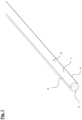
- figure 1 shows an inner pipe 1 which has three grooves 4 in its outer surface 2 . These grooves 4 serve to connect the inner tube 1 and an outer tube, this is in figure 3 denoted by the reference numeral 5, to accommodate a signal line 7 comprising a sensor.
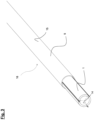
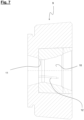
- the inner tube 1 is a cold-formed, here cold-drawn, stainless steel tube. While the grooves 4 are drawn into the outer surface 2 of the tube 1, the additional recesses 6 are milled into the outer surface 2 of the tube. These are in figure 2 to see.
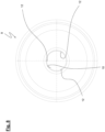
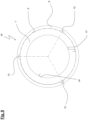
- the figures 7 and 8th show a drawing die 9 for drawing the inner tube 1.
- the drawing die 9 reduces the outer diameter of an incoming shell, so that the finished inner tube 1 has an outer diameter which is defined by the tool dimensions of the drawing die 9.
- the smallest diameter of the conical inner surface 10 of the tool is referred to as the tool dimension in the sense of the present application.
- This smallest inner diameter is at the drawing die 9 from figure 7 reached at the point marked 11.
- a supported or a flying drawing core can be used to draw the shell into the finished inner tube 1, which core forms the inner dimension, ie the inner diameter of the inner tube 1. However, this is not absolutely necessary.
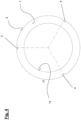
- figure 4 shows a cross section through the inner tube 1 in any plane outside the recesses 6.
- the inner surface of the inner tube 1 has the reference number 14.
- Three protruding sections 12 are provided on the inner surface 10 of the tool for drawing the grooves 4 into the outer surface 2 of the inner pipe 1 .
- These sections 12 projecting inwardly from the inner surface of the tool are spaced apart from one another by 120° in the circumferential direction.
- Each of the inwardly projecting sections has a part-circular cross-section, the pitch circle of each inwardly projecting section being less than 180° in relation to the tool inner surface 10 .
- the grooves 4 drawn in the outer surface 2 of the inner tube 1 by the drawing die 9 have a smaller width in the circumferential direction of the tube 1 than they are deep in the radial direction of the tube 1 .
- the inner pipe 1 After drawing through the drawing die 9, the inner pipe 1 not only has its external and internal dimensions, but also three grooves 4 spaced 120° apart.
- the drawing die 9 from the figures 7 and 8th is referred to as the second drawing die within the meaning of the present application.
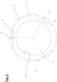
- FIG. 5 shows a sectional view of the tube in the area of the recess 6.
- Three recesses 6 are provided in the outer surface 2 of the inner tube 1, each of which serves to accommodate a sensor which is connected to a signal line 7. From the recesses 6 are in the perspective view figure 2 only two visible, the others are hidden by the pipe.
- Each of the recesses 6 adjoins a respective groove 4 in the sense that the groove 4 and the recess 6 form a coherent receiving space for the signal lines 7 and the sensor 8 .
- the signal lines 7 together with the pickups 8 are then glued into the grooves 4 or the recesses 6 .
- the bond it is only important that the bond is sufficiently stable to allow the inner tube 1 to be inserted into the outer tube 5 .
- the slots 4 are just dimensioned such that they each accommodate two signal lines 7 .
- the outer tube 5 In order to be able to produce the complete sensor, it is initially irrelevant how the outer tube 5 is produced or provided. Typically, the outer tube 5 will also be a cold-formed tube made of stainless steel.
- the outer diameter of the inner tube 1 is smaller than the inner diameter of the outer tube 5. In this way, the inner tube 1 can be inserted into the outer tube 5 with little force with little friction on the outer tube 5. In one embodiment, this work step is carried out manually. If the inner tube 1 and the outer tube 5 exhibit excessive friction when the inner tube 1 is inserted into the outer tube 5, the signal lines 7 and sensors 8 already arranged in the grooves 4 and recesses 6 can be damaged.
- the two concentrically arranged inner and outer tubes 1, 5 are then mechanically non-positively connected to one another to form a tube in that both tubes are drawn together on a drawing bench through a drawing die.
- the inner and outer tubes 1, 5 together with the signal lines 7 and the sensors 8 then form the sensor 16 according to the invention for a high-pressure line.
- the drawing die is referred to as the first drawing die.
- the first draw die has a configuration similar to that of the draw die figures 7 and 8th is similar, with the first drawing die having no protruding portions on the inner forming tool surface.
- the inner diameter of the outer pipe 5 is reduced in such a way that the inner surface of the outer pipe 5 rests on the outer surface 2 of the inner pipe 1 with a force fit.
- the wall thickness of the outer tube and the inner diameter of the outer tube is reduced by drawing the inner tube and the outer tube together through the first drawing die in such a way that the outer diameter of the inner tube is also reduced by at least 0.01 mm and um is reduced by at most 0.3 mm.
- the upper limit of a reduction in the outer diameter of the inner tube serves to prevent the installation space of the grooves 4 and recesses 6 from being reduced and the signal lines or the transducers from being damaged when the inner tube and outer tube are drawn together through the first drawing die.
- a change in the inner diameter of the inner pipe must be avoided in order not to change the surface properties of the inner surface of the inner pipe and not to change the pressure resistance of the pipe.
- the pitch circle which forms the groove 4 has a radius of 0.5 mm.
- the pitch circle is embedded in the outer surface 2 of the inner tube 1 in such a way that the width of the groove, measured as the connecting distance between the two edges in a direction perpendicular to the longitudinal axis of the inner tube 1, is 1.88 mm.
- the depth of the groove 4 is then 0.7 mm in this embodiment, measured between the deepest point of the groove and the Line connecting the two edges of the groove on the outer surface 2 and perpendicular to this line of connection.
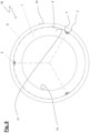
- figure 6 14 shows a cross-sectional view of the finished tube 14.
- FIG figure 3 after the inner tube 1 and outer tube 5 have been drawn together through the third drawing die. It can be seen here that three signal lines 7 are arranged in each of the grooves 4 . It can also be clearly seen that the outer surface 2 of the inner tube 1 is in contact with the inner surface 14 of the outer tube 5 .
- the outer surface of the outer tube 5 is denoted by the reference number 15 in the figures.
- figure 9 shows an embodiment of a sensor 16' according to the invention, in which the inner tube 1' has an outer surface 2' without grooves and recesses. Instead, three grooves 13 are drawn into the outer tube 5' which is pulled onto the inner tube 1'.
- the outer tube was drawn from a shell, using a drawing die and a supported drawing core as the tool. This drawing die forms the third drawing die within the meaning of the present application.
- the drawing core has on its outer tool surface, which defines the inner surface of the outer tube, three outwardly protruding sections, which draw the grooves 13 into the inner surface of the outer tube.
- three outwardly protruding sections which draw the grooves 13 into the inner surface of the outer tube.
- recesses in the inner surface 17' of the outer tube 5', in which recesses sensors are accommodated. These recesses can be introduced into the inner surface 17' by milling.
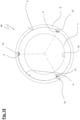
- figure 10 1 shows a schematic cross section through a sensor 16".
- both the inner surface 17' of the outer tube 5' and the outer surface 2 of the inner tube 1 each have four grooves 4, 13.
- the grooves 4 of the inner tube 1 and the grooves 13 of the outer tube 5 ' were made as for the inner tube 1 from the Figures 1 to 5 and for the outer tube 5' figure 9 was described.
- the grooves 4, 13 are arranged in such a way that they each define a common installation space.
- the inner tube and the outer tube with the signal lines 7 and the transducers together form the sensor 16, 16', 16" for a high-pressure line.
- the transducers are force transducers 8 in Form of strain gauges, which detect a force acting on the inner tube 1, 1'.
- the force transducers 8 are in engagement with the outer surface of the inner tube. Forces are exerted on the inner tube, in particular by the pressure of a fluid guided in the tube, so that the Sensor 16, 16', 16" is a pressure sensor for a high-pressure line.
Landscapes
- Engineering & Computer Science (AREA)
- Physics & Mathematics (AREA)
- Aviation & Aerospace Engineering (AREA)
- General Physics & Mathematics (AREA)
- Mechanical Engineering (AREA)
- General Engineering & Computer Science (AREA)
- Acoustics & Sound (AREA)
- Measuring Fluid Pressure (AREA)
- Rigid Pipes And Flexible Pipes (AREA)
- Force Measurement Appropriate To Specific Purposes (AREA)
Claims (14)
- Capteur (16, 16', 16") pour une conduite haute pression avecau moins un détecteur (8), au moins une ligne de signal (7) et un tube,dans lequel l'au moins un détecteur (8) est relié à l'au moins une ligne de signal (7),dans lequel le capteur (16, 16', 16") est un capteur de pression, dans lequel l'au moins un détecteur (8) est un capteur de force,dans lequel le capteur présente un tube extérieur (5, 5') en métal avec une surface extérieure (15), une surface intérieure (17, 17'), un diamètre extérieur et un diamètre intérieur etun tube intérieur (1, 1') en métal avec une surface extérieure (2, 2'), une surface intérieure (14, 14'), un diamètre extérieur et un diamètre intérieur,dans lequel le tube intérieur (1, 1') s'étend concentriquement dans le tube extérieur de sorte que le tube intérieur (1, 1') et le tube extérieur (5,5') forment ensemble le tube,dans lequel une épaisseur de paroi entière est, mesurée comme une moitié d'une différence entre le diamètre extérieur du tube extérieur (5, 5') et le diamètre intérieur du tube intérieur (1, 1'), égale ou supérieure au diamètre intérieur du tube intérieur (1, 1'),dans lequel dans la surface intérieure (17, 17') du tube extérieur (5, 5') ou dans la surface extérieure (2, 2') du tube intérieur (1, 1'), au moins une rainure (4, 13) s'étend dans un sens longitudinal du tube,dans lequel l'au moins une ligne de signal (7) est agencée dans la rainure (4, 13),dans lequel le détecteur (8) est agencé au moins dans la rainure (4, 13) ou dans au moins un évidement (6) introduit outre l'au moins une rainure (4, 13) au moins dans la surface extérieure (2, 2') du tube intérieur (1, 1') ou dans la surface intérieure (17, 17') du tube extérieur (5, 5'),dans lequel le tube extérieur (5, 5') loge à force sur le tube intérieur (1, 1').
- Capteur (16, 16', 16") selon la revendication précédente, caractérisé en ce que le capteurprésente trois rainures (4, 13) s'étendant au moins dans la surface intérieure du tube extérieur (5') ou dans la surface extérieure du tube intérieur (1, 1') dans un sens longitudinal du tube,dans lequel au moins une ligne de signal (7) est agencée dans chacune des trois rainures (4, 13),dans lequel respectivement un détecteur (8) relié à au moins une ligne de signal (7) est agencé au moins dans une des trois rainures (4, 13) ou dans trois évidements (6) contigus à respectivement une des rainures (4, 13) etdans lequel les détecteurs (8) sont agencés dans le sens longitudinal du tube de telle manière qu'un plan de section transversale soit perpendiculaire au sens longitudinal du tube, lequel coupe tous les trois détecteurs (8).
- Capteur (16, 16', 16") selon la revendication précédente, caractérisé en ce que les trois détecteurs (8) sont espacés respectivement de 120° dans le sens périphérique du tube les uns des autres.
- Capteur (16, 16', 16") selon la revendication 2 ou 3, caractérisé en ce que les trois détecteurs (8) sont des capteurs de force de sorte que le capteur (16, 16', 16") soit un capteur de pression.
- Capteur (16, 16', 16") selon la revendication précédente, caractérisé en ce que le capteur (16, 16', 16") présente en outre un thermomètre, dans lequel le thermomètre est agencé au moins dans une rainure (4, 13) ou dans au moins un évidement (6) introduit au moins dans la surface extérieure du tube intérieur (1) ou dans la surface intérieure du tube extérieur (5').
- Capteur (16, 16', 16") selon l'une quelconque des revendications précédentes, caractérisé en ce que le tube intérieur (1, 1') est un tube écroui avec une résistance à la traction de 900 N ou plus.
- Capteur (16, 16', 16") selon l'une quelconque des revendications précédentes, caractérisé en ce que le tube intérieur (1, 1') présente une extension supérieure à celle du tube extérieur.
- Capteur (16, 16', 16") selon l'une quelconque des revendications précédentes, caractérisé en ce que l'épaisseur de paroi entière s'élève au moins à 3 mm.
- Procédé de fabrication d'un capteur (16, 16', 16") pour une conduite haute pression avec les étapes consistant àfournir un tube extérieur (5, 5') en métal avec une surface extérieure, une surface intérieure, un diamètre extérieur et un diamètre intérieur,fournir un tube intérieur (1, 1') en métal avec une surface extérieure, une surface intérieure, un diamètre extérieur et un diamètre intérieur,dans lequel le diamètre extérieur du tube intérieur (1, 1') est inférieur au diamètre intérieur du tube extérieur (5, 5'),dans lequel une épaisseur de paroi entière est, mesurée comme une moitié d'une différence entre le diamètre extérieur du tube extérieur (5, 5') et le diamètre intérieur du tube intérieur, égale ou supérieure au diamètre intérieur du tube intérieur (1, 1'), introduire au moins une rainure (4, 13) s'étendant dans un sens longitudinal du tube extérieur (5') ou du tube intérieur (1) au moins dans la surface intérieure du tube extérieur (5') ou dans la surface extérieure du tube intérieur (1),dans lequel le procédé présente en outre les étapes consistant àagencer au moins une ligne de signal (7) dans la rainure (4, 13),agencer au moins un détecteur (8) relié à la ligne de signal (7) au moins dans la rainure (4, 13) ou dans au moins un évidement (6) introduit au moins dans la surface extérieure du tube intérieur (1) ou dans la surface intérieure du tube extérieur (5'), dans lequel l'au moins un détecteur (8) est un capteur de force qui est en prise avec le tube intérieur (1, 1') de telle manière qu'il détecte dans un fonctionnement du capteur (16, 16', 16") une force exercée sur le tube intérieur (1, 1'), introduire le tube intérieur dans le tube extérieur (5, 5') de sorte que le tube intérieur (1, 1') s'étende dans le tube extérieur (5, 5'), ettirer le tube intérieur (1, 1') et le tube extérieur (5, 5') ensemble par une première matrice de traction avec une surface intérieure d'outil formant la surface extérieure du tube extérieur,dans lequel un diamètre d'outil de la surface intérieure d'outil de la première matrice de traction est choisi de telle manière que le diamètre intérieur du tube extérieur (5, 5') soit diminué par la traction de telle manière qu'après la traction, le tube extérieur (5, 5') loge à force sur le tube intérieur de sorte que le tube intérieur (1, 1') et le tube extérieur (5, 5') forment ensemble un tube.
- Procédé selon la revendication précédente, caractérisé en ce qu'une épaisseur de paroi du tube extérieur (5, 5') et le diamètre intérieur du tube extérieur (5, 5') sont réduits par la traction du tube intérieur (1, 1') et du tube extérieur (5, 5') ensemble par la première matrice de traction de telle manière que le diamètre extérieur du tube intérieur (1, 1') soit réduit d'au moins 0,01 mm et d'au plus 0,3 mm.
- Procédé selon la revendication précédente, caractérisé en ce que le diamètre intérieur du tube intérieur (1, 1') n'est pas réduit par la traction du tube intérieur (1, 1') et du tube extérieur (5, 5') ensemble par la première matrice de traction.
- Procédé selon l'une quelconque des revendications 9 à 11, caractérisé en ce que la fourniture du tube intérieur (1) et l'introduction de la rainure (4, 13) dans la surface extérieure du tube intérieur (1) comportent les étapes consistant àfournir une loupe en métal,tirer la loupe par une seconde matrice de traction avec une surface intérieure d'outil formant la surface extérieure du tube intérieur (1) au tube intérieur (1),dans lequel un diamètre d'outil de la surface intérieure d'outil de la seconde matrice de traction est choisi de telle manière que le diamètre extérieur du tube intérieur (1) soit inférieur au diamètre intérieur du tube extérieur etdans lequel la surface intérieure d'outil de la seconde matrice de traction présente au moins une section en saillie vers l'intérieur de telle manière que dans la surface extérieure du tube intérieur, l'au moins une rainure (4, 13) s'étendant dans le sens longitudinal du tube intérieur (1) soit tirée.
- Procédé selon la revendication 12, caractérisé en ce que la surface intérieure d'outil de la seconde matrice de traction présente une pluralité de sections en saillie vers l'intérieur de sorte qu'une pluralité de rainures (4) soit tirée dans le sens longitudinal dans la surface extérieure du tube intérieur (1).
- Procédé selon l'une quelconque des revendications 9 à 13, caractérisé en ce qu'avant l'étape d'introduction du tube intérieur (1) dans le tube extérieur (5, 5'), au moins le tube intérieur (1) est usiné par enlèvement de copeaux de sorte que l'au moins un évidement (6) soit formé dans la surface extérieure du tube intérieur (1), dans lequel l'évidement (6) est contigu à au moins une rainure (4, 13).
Applications Claiming Priority (2)
| Application Number | Priority Date | Filing Date | Title |
|---|---|---|---|
| DE102015122296.5A DE102015122296A1 (de) | 2015-12-18 | 2015-12-18 | Sensor für eine Hochdruckleitung sowie Verfahren zu seiner Herstellung |
| PCT/EP2016/081539 WO2017103181A1 (fr) | 2015-12-18 | 2016-12-16 | Capteur pour une conduite haute pression et procédé de fabrication associé |
Publications (2)
| Publication Number | Publication Date |
|---|---|
| EP3391007A1 EP3391007A1 (fr) | 2018-10-24 |
| EP3391007B1 true EP3391007B1 (fr) | 2023-04-26 |
Family
ID=57714581
Family Applications (1)
| Application Number | Title | Priority Date | Filing Date |
|---|---|---|---|
| EP16822150.5A Active EP3391007B1 (fr) | 2015-12-18 | 2016-12-16 | Capteur pour tuyau à haute pression et son procédé de fabrication |
Country Status (8)
| Country | Link |
|---|---|
| US (1) | US11112063B2 (fr) |
| EP (1) | EP3391007B1 (fr) |
| JP (1) | JP6805253B2 (fr) |
| KR (1) | KR102694081B1 (fr) |
| CN (1) | CN108603801B (fr) |
| DE (1) | DE102015122296A1 (fr) |
| ES (1) | ES2949350T3 (fr) |
| WO (1) | WO2017103181A1 (fr) |
Families Citing this family (7)
| Publication number | Priority date | Publication date | Assignee | Title |
|---|---|---|---|---|
| US20200348018A1 (en) * | 2017-11-17 | 2020-11-05 | Sandvik Intellectual Property Ab | Boiler Tube and Boiler Tube Unit and Furnace |
| CN112136022A (zh) * | 2018-05-16 | 2020-12-25 | 山特维克材料技术公司 | 具有传感器布置结构的金属管结构 |
| DE102019104536A1 (de) * | 2019-02-22 | 2020-08-27 | Sandvik Materials Technology Deutschland Gmbh | Rohrstruktur und Verfahren zum Herstellen einer solchen Rohrstruktur |
| EP4212766A1 (fr) * | 2022-01-13 | 2023-07-19 | Hübner, Dietmar Roland | Système de tuyauterie permettant de conduire des fluides réactifs et son utilisation |
| CN115540667A (zh) * | 2022-09-19 | 2022-12-30 | 江苏迪威高压科技股份有限公司 | 一种换热器用的高压管件及其使用方法 |
| CN116379356B (zh) * | 2023-04-13 | 2026-02-13 | 贵州和泰达科技有限公司 | 一种在线监测金属管内壁结垢堵塞趋势的装置和方法 |
| CN118464783B (zh) * | 2024-07-11 | 2024-09-20 | 南通市新隆玻璃制品有限公司 | 一种玻璃管内表面缺陷检测装置 |
Citations (1)
| Publication number | Priority date | Publication date | Assignee | Title |
|---|---|---|---|---|
| US6463813B1 (en) * | 1999-06-25 | 2002-10-15 | Weatherford/Lamb, Inc. | Displacement based pressure sensor measuring unsteady pressure in a pipe |
Family Cites Families (29)
| Publication number | Priority date | Publication date | Assignee | Title |
|---|---|---|---|---|
| JPS5839923A (ja) * | 1981-09-02 | 1983-03-08 | Sumitomo Metal Ind Ltd | 2重管 |
| US4558721A (en) * | 1982-09-28 | 1985-12-17 | Apx Group Inc. | Double walled tubing |
| FR2563900B1 (fr) * | 1984-05-04 | 1986-10-31 | Novatome | Tube a double paroi pour un echangeur de chaleur et procede de realisation de ce tube |
| JPS62121533U (fr) * | 1986-01-23 | 1987-08-01 | ||
| DE3805838C2 (de) * | 1987-11-24 | 1997-03-13 | Km Europa Metal Ag | Verfahren und Vorrichtung zum Ziehen von nahtlosen Metallrohren |
| DE4105701A1 (de) * | 1990-03-08 | 1991-09-12 | Mannesmann Ag | Verfahren zur herstellung eines metallischen, dickwandigen hochdruckrohres |
| US5343738A (en) * | 1992-10-16 | 1994-09-06 | Furon Company | Double walled containment fuel transfer hose |
| DE4428875C2 (de) * | 1994-08-08 | 1996-10-24 | Mannesmann Ag | Verfahren zur Herstellung einer hohlen Achse |
| US6634388B1 (en) * | 1998-07-22 | 2003-10-21 | Safetyliner Systems, Llc | Annular fluid manipulation in lined tubular systems |
| DE19963786A1 (de) * | 1999-12-30 | 2001-07-05 | Aktiv Sensor Gmbh | Druckmesselement mit piezoresistiven Halbleiterelementen |
| DE10018665B4 (de) * | 2000-04-14 | 2006-12-14 | First Sensor Technology Gmbh | Längensensor mit Piezoeffekt |
| WO2006034724A1 (fr) * | 2004-09-28 | 2006-04-06 | Gall & Seitz Gmbh | Tuyau a paroi double |
| JP2006132905A (ja) | 2004-11-09 | 2006-05-25 | Denso Corp | 冷凍サイクル |
| EP1857194B3 (fr) | 2004-12-21 | 2013-09-04 | Bergrohr GmbH Siegen | Tuyau multicouche et son procédé de fabrication |
| US8496647B2 (en) * | 2007-12-18 | 2013-07-30 | Intuitive Surgical Operations, Inc. | Ribbed force sensor |
| US8344905B2 (en) * | 2005-03-31 | 2013-01-01 | Intelliserv, Llc | Method and conduit for transmitting signals |
| CA2658125C (fr) * | 2006-08-01 | 2013-11-19 | Afl Telecommunications Llc | Tubes metalliques encastres pourvus d'un raccord de compression et leur procede de fabrication |
| KR20070049187A (ko) * | 2007-02-28 | 2007-05-10 | 갈 운트 자잇츠 게엠베하 | 이중 벽 파이프 |
| CN101776184A (zh) | 2009-12-14 | 2010-07-14 | 深圳市协诚机电设备工程有限公司 | 一种双层金属管及其制造模具和制造方法 |
| BRPI1002661A2 (pt) * | 2010-03-15 | 2012-11-27 | Bundy Refrigeracao Brasil Ind E Com Ltda | processo da junção do tubo bimetálico com terminais de cobre e produto obtido |
| GB201122364D0 (en) * | 2011-12-28 | 2012-02-01 | Wellstream Int Ltd | Flexible pipe body and method |
| KR101137158B1 (ko) * | 2011-12-29 | 2012-04-20 | (주) 금영이티에스 | 인발 가공에 의한 자동차 변속기용 시프트 샤프트 및 그 제조방법 |
| CN102606841A (zh) * | 2012-04-01 | 2012-07-25 | 常熟市异型钢管有限公司 | 船舶油路保护装置及保护套管的加工方法和加工用的芯棒 |
| US10197212B2 (en) * | 2014-11-25 | 2019-02-05 | Halliburton Energy Services, Inc. | Smart subsea pipeline |
| EP3086011B1 (fr) * | 2015-04-21 | 2019-07-31 | Airbus Operations GmbH | Tuyau à double paroi avec capacité de chauffage intégrée pour un aéronef ou un engin spatial |
| DE102015122297A1 (de) * | 2015-12-18 | 2017-06-22 | Sandvik Materials Technology Deutschland Gmbh | Verfahren zum Herstellen eines Hochdruckrohres |
| WO2017102227A1 (fr) * | 2015-12-18 | 2017-06-22 | Sandvik Materials Technology Deutschland Gmbh | Procédé de fabrication d'un tube de métal ainsi que tube de métal |
| US20180095455A1 (en) * | 2016-10-03 | 2018-04-05 | Fmc Technologies, Inc. | Maintenance condition sensing device |
| WO2018091543A1 (fr) * | 2016-11-16 | 2018-05-24 | Sandvik Intellectual Property Ab | Système et procédé de fabrication d'un système |
-
2015
- 2015-12-18 DE DE102015122296.5A patent/DE102015122296A1/de active Pending
-
2016
- 2016-12-16 CN CN201680074499.8A patent/CN108603801B/zh active Active
- 2016-12-16 WO PCT/EP2016/081539 patent/WO2017103181A1/fr not_active Ceased
- 2016-12-16 US US16/061,480 patent/US11112063B2/en active Active
- 2016-12-16 EP EP16822150.5A patent/EP3391007B1/fr active Active
- 2016-12-16 JP JP2018532125A patent/JP6805253B2/ja active Active
- 2016-12-16 KR KR1020187020043A patent/KR102694081B1/ko active Active
- 2016-12-16 ES ES16822150T patent/ES2949350T3/es active Active
Patent Citations (1)
| Publication number | Priority date | Publication date | Assignee | Title |
|---|---|---|---|---|
| US6463813B1 (en) * | 1999-06-25 | 2002-10-15 | Weatherford/Lamb, Inc. | Displacement based pressure sensor measuring unsteady pressure in a pipe |
Also Published As
| Publication number | Publication date |
|---|---|
| ES2949350T3 (es) | 2023-09-27 |
| JP2019502918A (ja) | 2019-01-31 |
| WO2017103181A1 (fr) | 2017-06-22 |
| DE102015122296A1 (de) | 2017-06-22 |
| KR102694081B1 (ko) | 2024-08-09 |
| CN108603801B (zh) | 2020-09-29 |
| EP3391007A1 (fr) | 2018-10-24 |
| CN108603801A (zh) | 2018-09-28 |
| JP6805253B2 (ja) | 2020-12-23 |
| US11112063B2 (en) | 2021-09-07 |
| US20200025339A1 (en) | 2020-01-23 |
| KR20180095859A (ko) | 2018-08-28 |
Similar Documents
| Publication | Publication Date | Title |
|---|---|---|
| EP3391007B1 (fr) | Capteur pour tuyau à haute pression et son procédé de fabrication | |
| EP3389887B1 (fr) | Procédé de fabrication d'un tube haute pression | |
| EP2855042B1 (fr) | Outil et procédé de façonnage pour élargir une ouverture au moyen d'un dispositif d'élargissement | |
| DE102013006009B3 (de) | Verfahren zum Herstellen eines Balgs und/oder Balg | |
| EP0178248A2 (fr) | Tube d'acier pour arrêt de crique pour canalisation de gaz | |
| DE2926447A1 (de) | Dauerfestes verbundstueck und verfahren zur herstellung desselben | |
| DE102009036347B4 (de) | Verfahren zur Herstellung einer Bordscheibe für ein Pendelrollenlager und Pendelrollenlager mit einer verfahrensgemäß hergestellten Bordscheibe | |
| DE102009046886A1 (de) | Messgerät | |
| DE102013015676A1 (de) | Verfahren zur Herstellung eines Sinterteils mit höhenpräziser Formteilhöhe sowie Teilesatz aus Sinterfügeteilen | |
| DE102005019182B4 (de) | Abgasreinigungsvorrichtung und Verfahren zu deren Herstellung | |
| EP0922510B1 (fr) | Méthode et appareil pour le formage d'un tube dans une plaque de tubes | |
| DE3320759C1 (de) | Hydraulisch beaufschlagbarer Zylinder,fuer ein Ausbaugestell sowie Verfahren zu seiner Herstellung | |
| DE3230444C2 (de) | Bördelpresse für Metallrohre | |
| DE10000796A1 (de) | Verfahren und Vorrichtung zur Autofrettage von fertig gebogenen oder sonst umgeformten Rohleitungen | |
| DE2919615A1 (de) | Verfahren zur herstellung eines mehrfachrohres oder einer rundstange mit rohrummantelung | |
| EP2170540A1 (fr) | Procédé de fabrication de tubes sans soudure fabriqués thermiquement à propriétés optimisées de fatigue à l'état soudé | |
| DE102020102724B3 (de) | Verfahren zur Herstellung einer Hochdruck-Hydraulikleitung sowie Radialpresse zur Durchführung des Verfahrens | |
| DE19757946A1 (de) | Rohrverbindung | |
| DE102014106927A1 (de) | Messgerät, insbesondere Durchflussmessgerät, und Verfahren zur zur Herstellung eines Messrohres für ein Messgerät | |
| DE102020105956A1 (de) | Verfahren zum Überprüfen einer Schweißnahthaltbarkeit | |
| DE102014224469A1 (de) | Verfahren zum Herstellen einer Körperstruktur eines Flugkörpers sowie Vorrichtung einer Flugkörperstruktur | |
| DE102018131940A1 (de) | Verfahren zur Herstellung von metallischen Rohrmembranen für Druckmittler | |
| DE102016222605A1 (de) | Verfahren zur Herstellung eines Torsionsrohres sowie Fertigungseinrichtung hierzu | |
| EP0892689B1 (fr) | Procede pour augmenter l'epaisseur de la paroi de profiles creux | |
| DE102004059091A1 (de) | Verfahren zur Herstellung von warmgefertigten nahtlosen Rohren |
Legal Events
| Date | Code | Title | Description |
|---|---|---|---|
| STAA | Information on the status of an ep patent application or granted ep patent |
Free format text: STATUS: UNKNOWN |
|
| STAA | Information on the status of an ep patent application or granted ep patent |
Free format text: STATUS: THE INTERNATIONAL PUBLICATION HAS BEEN MADE |
|
| PUAI | Public reference made under article 153(3) epc to a published international application that has entered the european phase |
Free format text: ORIGINAL CODE: 0009012 |
|
| STAA | Information on the status of an ep patent application or granted ep patent |
Free format text: STATUS: REQUEST FOR EXAMINATION WAS MADE |
|
| 17P | Request for examination filed |
Effective date: 20180718 |
|
| AK | Designated contracting states |
Kind code of ref document: A1 Designated state(s): AL AT BE BG CH CY CZ DE DK EE ES FI FR GB GR HR HU IE IS IT LI LT LU LV MC MK MT NL NO PL PT RO RS SE SI SK SM TR |
|
| AX | Request for extension of the european patent |
Extension state: BA ME |
|
| DAV | Request for validation of the european patent (deleted) | ||
| DAX | Request for extension of the european patent (deleted) | ||
| STAA | Information on the status of an ep patent application or granted ep patent |
Free format text: STATUS: EXAMINATION IS IN PROGRESS |
|
| 17Q | First examination report despatched |
Effective date: 20200916 |
|
| REG | Reference to a national code |
Ref country code: DE Ref legal event code: R079 Ref document number: 502016015728 Country of ref document: DE Free format text: PREVIOUS MAIN CLASS: G01M0005000000 Ipc: B21C0001220000 |
|
| GRAP | Despatch of communication of intention to grant a patent |
Free format text: ORIGINAL CODE: EPIDOSNIGR1 |
|
| STAA | Information on the status of an ep patent application or granted ep patent |
Free format text: STATUS: GRANT OF PATENT IS INTENDED |
|
| RAP3 | Party data changed (applicant data changed or rights of an application transferred) |
Owner name: ALLEIMA GMBH |
|
| RIC1 | Information provided on ipc code assigned before grant |
Ipc: B21C 37/15 20060101ALI20221026BHEP Ipc: F17D 5/06 20060101ALI20221026BHEP Ipc: F17D 5/02 20060101ALI20221026BHEP Ipc: G01M 5/00 20060101ALI20221026BHEP Ipc: B21C 1/22 20060101AFI20221026BHEP |
|
| INTG | Intention to grant announced |
Effective date: 20221116 |
|
| GRAS | Grant fee paid |
Free format text: ORIGINAL CODE: EPIDOSNIGR3 |
|
| GRAA | (expected) grant |
Free format text: ORIGINAL CODE: 0009210 |
|
| STAA | Information on the status of an ep patent application or granted ep patent |
Free format text: STATUS: THE PATENT HAS BEEN GRANTED |
|
| AK | Designated contracting states |
Kind code of ref document: B1 Designated state(s): AL AT BE BG CH CY CZ DE DK EE ES FI FR GB GR HR HU IE IS IT LI LT LU LV MC MK MT NL NO PL PT RO RS SE SI SK SM TR |
|
| REG | Reference to a national code |
Ref country code: GB Ref legal event code: FG4D Free format text: NOT ENGLISH |
|
| REG | Reference to a national code |
Ref country code: CH Ref legal event code: EP |
|
| REG | Reference to a national code |
Ref country code: DE Ref legal event code: R096 Ref document number: 502016015728 Country of ref document: DE |
|
| REG | Reference to a national code |
Ref country code: AT Ref legal event code: REF Ref document number: 1562468 Country of ref document: AT Kind code of ref document: T Effective date: 20230515 |
|
| REG | Reference to a national code |
Ref country code: IE Ref legal event code: FG4D Free format text: LANGUAGE OF EP DOCUMENT: GERMAN |
|
| P01 | Opt-out of the competence of the unified patent court (upc) registered |
Effective date: 20230526 |
|
| REG | Reference to a national code |
Ref country code: LT Ref legal event code: MG9D |
|
| REG | Reference to a national code |
Ref country code: NL Ref legal event code: MP Effective date: 20230426 |
|
| REG | Reference to a national code |
Ref country code: ES Ref legal event code: FG2A Ref document number: 2949350 Country of ref document: ES Kind code of ref document: T3 Effective date: 20230927 |
|
| PG25 | Lapsed in a contracting state [announced via postgrant information from national office to epo] |
Ref country code: NL Free format text: LAPSE BECAUSE OF FAILURE TO SUBMIT A TRANSLATION OF THE DESCRIPTION OR TO PAY THE FEE WITHIN THE PRESCRIBED TIME-LIMIT Effective date: 20230426 |
|
| PG25 | Lapsed in a contracting state [announced via postgrant information from national office to epo] |
Ref country code: SE Free format text: LAPSE BECAUSE OF FAILURE TO SUBMIT A TRANSLATION OF THE DESCRIPTION OR TO PAY THE FEE WITHIN THE PRESCRIBED TIME-LIMIT Effective date: 20230426 Ref country code: PT Free format text: LAPSE BECAUSE OF FAILURE TO SUBMIT A TRANSLATION OF THE DESCRIPTION OR TO PAY THE FEE WITHIN THE PRESCRIBED TIME-LIMIT Effective date: 20230828 Ref country code: NO Free format text: LAPSE BECAUSE OF FAILURE TO SUBMIT A TRANSLATION OF THE DESCRIPTION OR TO PAY THE FEE WITHIN THE PRESCRIBED TIME-LIMIT Effective date: 20230726 |
|
| PG25 | Lapsed in a contracting state [announced via postgrant information from national office to epo] |
Ref country code: RS Free format text: LAPSE BECAUSE OF FAILURE TO SUBMIT A TRANSLATION OF THE DESCRIPTION OR TO PAY THE FEE WITHIN THE PRESCRIBED TIME-LIMIT Effective date: 20230426 Ref country code: PL Free format text: LAPSE BECAUSE OF FAILURE TO SUBMIT A TRANSLATION OF THE DESCRIPTION OR TO PAY THE FEE WITHIN THE PRESCRIBED TIME-LIMIT Effective date: 20230426 Ref country code: LV Free format text: LAPSE BECAUSE OF FAILURE TO SUBMIT A TRANSLATION OF THE DESCRIPTION OR TO PAY THE FEE WITHIN THE PRESCRIBED TIME-LIMIT Effective date: 20230426 Ref country code: LT Free format text: LAPSE BECAUSE OF FAILURE TO SUBMIT A TRANSLATION OF THE DESCRIPTION OR TO PAY THE FEE WITHIN THE PRESCRIBED TIME-LIMIT Effective date: 20230426 Ref country code: IS Free format text: LAPSE BECAUSE OF FAILURE TO SUBMIT A TRANSLATION OF THE DESCRIPTION OR TO PAY THE FEE WITHIN THE PRESCRIBED TIME-LIMIT Effective date: 20230826 Ref country code: HR Free format text: LAPSE BECAUSE OF FAILURE TO SUBMIT A TRANSLATION OF THE DESCRIPTION OR TO PAY THE FEE WITHIN THE PRESCRIBED TIME-LIMIT Effective date: 20230426 Ref country code: GR Free format text: LAPSE BECAUSE OF FAILURE TO SUBMIT A TRANSLATION OF THE DESCRIPTION OR TO PAY THE FEE WITHIN THE PRESCRIBED TIME-LIMIT Effective date: 20230727 |
|
| PG25 | Lapsed in a contracting state [announced via postgrant information from national office to epo] |
Ref country code: FI Free format text: LAPSE BECAUSE OF FAILURE TO SUBMIT A TRANSLATION OF THE DESCRIPTION OR TO PAY THE FEE WITHIN THE PRESCRIBED TIME-LIMIT Effective date: 20230426 |
|
| PG25 | Lapsed in a contracting state [announced via postgrant information from national office to epo] |
Ref country code: SK Free format text: LAPSE BECAUSE OF FAILURE TO SUBMIT A TRANSLATION OF THE DESCRIPTION OR TO PAY THE FEE WITHIN THE PRESCRIBED TIME-LIMIT Effective date: 20230426 |
|
| REG | Reference to a national code |
Ref country code: DE Ref legal event code: R097 Ref document number: 502016015728 Country of ref document: DE |
|
| PG25 | Lapsed in a contracting state [announced via postgrant information from national office to epo] |
Ref country code: SM Free format text: LAPSE BECAUSE OF FAILURE TO SUBMIT A TRANSLATION OF THE DESCRIPTION OR TO PAY THE FEE WITHIN THE PRESCRIBED TIME-LIMIT Effective date: 20230426 Ref country code: SK Free format text: LAPSE BECAUSE OF FAILURE TO SUBMIT A TRANSLATION OF THE DESCRIPTION OR TO PAY THE FEE WITHIN THE PRESCRIBED TIME-LIMIT Effective date: 20230426 Ref country code: RO Free format text: LAPSE BECAUSE OF FAILURE TO SUBMIT A TRANSLATION OF THE DESCRIPTION OR TO PAY THE FEE WITHIN THE PRESCRIBED TIME-LIMIT Effective date: 20230426 Ref country code: EE Free format text: LAPSE BECAUSE OF FAILURE TO SUBMIT A TRANSLATION OF THE DESCRIPTION OR TO PAY THE FEE WITHIN THE PRESCRIBED TIME-LIMIT Effective date: 20230426 Ref country code: DK Free format text: LAPSE BECAUSE OF FAILURE TO SUBMIT A TRANSLATION OF THE DESCRIPTION OR TO PAY THE FEE WITHIN THE PRESCRIBED TIME-LIMIT Effective date: 20230426 Ref country code: CZ Free format text: LAPSE BECAUSE OF FAILURE TO SUBMIT A TRANSLATION OF THE DESCRIPTION OR TO PAY THE FEE WITHIN THE PRESCRIBED TIME-LIMIT Effective date: 20230426 |
|
| PLBE | No opposition filed within time limit |
Free format text: ORIGINAL CODE: 0009261 |
|
| STAA | Information on the status of an ep patent application or granted ep patent |
Free format text: STATUS: NO OPPOSITION FILED WITHIN TIME LIMIT |
|
| 26N | No opposition filed |
Effective date: 20240129 |
|
| PG25 | Lapsed in a contracting state [announced via postgrant information from national office to epo] |
Ref country code: SI Free format text: LAPSE BECAUSE OF FAILURE TO SUBMIT A TRANSLATION OF THE DESCRIPTION OR TO PAY THE FEE WITHIN THE PRESCRIBED TIME-LIMIT Effective date: 20230426 |
|
| PG25 | Lapsed in a contracting state [announced via postgrant information from national office to epo] |
Ref country code: SI Free format text: LAPSE BECAUSE OF FAILURE TO SUBMIT A TRANSLATION OF THE DESCRIPTION OR TO PAY THE FEE WITHIN THE PRESCRIBED TIME-LIMIT Effective date: 20230426 Ref country code: IT Free format text: LAPSE BECAUSE OF FAILURE TO SUBMIT A TRANSLATION OF THE DESCRIPTION OR TO PAY THE FEE WITHIN THE PRESCRIBED TIME-LIMIT Effective date: 20230426 |
|
| REG | Reference to a national code |
Ref country code: CH Ref legal event code: PL |
|
| PG25 | Lapsed in a contracting state [announced via postgrant information from national office to epo] |
Ref country code: LU Free format text: LAPSE BECAUSE OF NON-PAYMENT OF DUE FEES Effective date: 20231216 |
|
| PG25 | Lapsed in a contracting state [announced via postgrant information from national office to epo] |
Ref country code: MC Free format text: LAPSE BECAUSE OF FAILURE TO SUBMIT A TRANSLATION OF THE DESCRIPTION OR TO PAY THE FEE WITHIN THE PRESCRIBED TIME-LIMIT Effective date: 20230426 |
|
| REG | Reference to a national code |
Ref country code: BE Ref legal event code: MM Effective date: 20231231 |
|
| PG25 | Lapsed in a contracting state [announced via postgrant information from national office to epo] |
Ref country code: MC Free format text: LAPSE BECAUSE OF FAILURE TO SUBMIT A TRANSLATION OF THE DESCRIPTION OR TO PAY THE FEE WITHIN THE PRESCRIBED TIME-LIMIT Effective date: 20230426 Ref country code: LU Free format text: LAPSE BECAUSE OF NON-PAYMENT OF DUE FEES Effective date: 20231216 |
|
| REG | Reference to a national code |
Ref country code: IE Ref legal event code: MM4A |
|
| PG25 | Lapsed in a contracting state [announced via postgrant information from national office to epo] |
Ref country code: IE Free format text: LAPSE BECAUSE OF NON-PAYMENT OF DUE FEES Effective date: 20231216 |
|
| PG25 | Lapsed in a contracting state [announced via postgrant information from national office to epo] |
Ref country code: BE Free format text: LAPSE BECAUSE OF NON-PAYMENT OF DUE FEES Effective date: 20231231 |
|
| PG25 | Lapsed in a contracting state [announced via postgrant information from national office to epo] |
Ref country code: CH Free format text: LAPSE BECAUSE OF NON-PAYMENT OF DUE FEES Effective date: 20231231 |
|
| PG25 | Lapsed in a contracting state [announced via postgrant information from national office to epo] |
Ref country code: IE Free format text: LAPSE BECAUSE OF NON-PAYMENT OF DUE FEES Effective date: 20231216 Ref country code: CH Free format text: LAPSE BECAUSE OF NON-PAYMENT OF DUE FEES Effective date: 20231231 Ref country code: BE Free format text: LAPSE BECAUSE OF NON-PAYMENT OF DUE FEES Effective date: 20231231 |
|
| PG25 | Lapsed in a contracting state [announced via postgrant information from national office to epo] |
Ref country code: BG Free format text: LAPSE BECAUSE OF FAILURE TO SUBMIT A TRANSLATION OF THE DESCRIPTION OR TO PAY THE FEE WITHIN THE PRESCRIBED TIME-LIMIT Effective date: 20230426 |
|
| PG25 | Lapsed in a contracting state [announced via postgrant information from national office to epo] |
Ref country code: BG Free format text: LAPSE BECAUSE OF FAILURE TO SUBMIT A TRANSLATION OF THE DESCRIPTION OR TO PAY THE FEE WITHIN THE PRESCRIBED TIME-LIMIT Effective date: 20230426 |
|
| PG25 | Lapsed in a contracting state [announced via postgrant information from national office to epo] |
Ref country code: CY Free format text: LAPSE BECAUSE OF FAILURE TO SUBMIT A TRANSLATION OF THE DESCRIPTION OR TO PAY THE FEE WITHIN THE PRESCRIBED TIME-LIMIT; INVALID AB INITIO Effective date: 20161216 |
|
| PG25 | Lapsed in a contracting state [announced via postgrant information from national office to epo] |
Ref country code: HU Free format text: LAPSE BECAUSE OF FAILURE TO SUBMIT A TRANSLATION OF THE DESCRIPTION OR TO PAY THE FEE WITHIN THE PRESCRIBED TIME-LIMIT; INVALID AB INITIO Effective date: 20161216 |
|
| PG25 | Lapsed in a contracting state [announced via postgrant information from national office to epo] |
Ref country code: TR Free format text: LAPSE BECAUSE OF FAILURE TO SUBMIT A TRANSLATION OF THE DESCRIPTION OR TO PAY THE FEE WITHIN THE PRESCRIBED TIME-LIMIT Effective date: 20230426 |
|
| PGFP | Annual fee paid to national office [announced via postgrant information from national office to epo] |
Ref country code: DE Payment date: 20251104 Year of fee payment: 10 |
|
| PGFP | Annual fee paid to national office [announced via postgrant information from national office to epo] |
Ref country code: GB Payment date: 20251114 Year of fee payment: 10 |
|
| PGFP | Annual fee paid to national office [announced via postgrant information from national office to epo] |
Ref country code: AT Payment date: 20251126 Year of fee payment: 10 |
|
| PGFP | Annual fee paid to national office [announced via postgrant information from national office to epo] |
Ref country code: FR Payment date: 20251124 Year of fee payment: 10 |
|
| PGFP | Annual fee paid to national office [announced via postgrant information from national office to epo] |
Ref country code: ES Payment date: 20260119 Year of fee payment: 10 |