EP3390899B1 - Additional headlamp for vehicles - Google Patents
Additional headlamp for vehicles Download PDFInfo
- Publication number
- EP3390899B1 EP3390899B1 EP16819419.9A EP16819419A EP3390899B1 EP 3390899 B1 EP3390899 B1 EP 3390899B1 EP 16819419 A EP16819419 A EP 16819419A EP 3390899 B1 EP3390899 B1 EP 3390899B1
- Authority
- EP
- European Patent Office
- Prior art keywords
- light
- headlamp
- auxiliary
- module
- headlight
- Prior art date
- Legal status (The legal status is an assumption and is not a legal conclusion. Google has not performed a legal analysis and makes no representation as to the accuracy of the status listed.)
- Active
Links
- 238000009826 distribution Methods 0.000 claims description 76
- 238000001816 cooling Methods 0.000 claims description 18
- 238000003384 imaging method Methods 0.000 claims description 17
- 230000008878 coupling Effects 0.000 claims description 5
- 238000010168 coupling process Methods 0.000 claims description 5
- 238000005859 coupling reaction Methods 0.000 claims description 5
- 238000005286 illumination Methods 0.000 claims 2
- 230000005855 radiation Effects 0.000 claims 1
- 230000002349 favourable effect Effects 0.000 description 9
- 230000003287 optical effect Effects 0.000 description 9
- 238000010276 construction Methods 0.000 description 8
- 238000004519 manufacturing process Methods 0.000 description 6
- 230000008901 benefit Effects 0.000 description 4
- 239000000463 material Substances 0.000 description 4
- 230000008859 change Effects 0.000 description 3
- 230000009286 beneficial effect Effects 0.000 description 2
- 238000009434 installation Methods 0.000 description 2
- 239000011159 matrix material Substances 0.000 description 2
- 230000006978 adaptation Effects 0.000 description 1
- 230000003044 adaptive effect Effects 0.000 description 1
- 239000000853 adhesive Substances 0.000 description 1
- 230000001070 adhesive effect Effects 0.000 description 1
- 230000004075 alteration Effects 0.000 description 1
- 238000006880 cross-coupling reaction Methods 0.000 description 1
- 230000000694 effects Effects 0.000 description 1
- 239000013013 elastic material Substances 0.000 description 1
- 238000005516 engineering process Methods 0.000 description 1
- 239000011521 glass Substances 0.000 description 1
- 238000001746 injection moulding Methods 0.000 description 1
- 239000007788 liquid Substances 0.000 description 1
- 238000012423 maintenance Methods 0.000 description 1
- 238000000034 method Methods 0.000 description 1
- -1 photopolymers Substances 0.000 description 1
- 239000004417 polycarbonate Substances 0.000 description 1
- 229920000515 polycarbonate Polymers 0.000 description 1
- 229920001296 polysiloxane Polymers 0.000 description 1
- 238000001303 quality assessment method Methods 0.000 description 1
- 230000009467 reduction Effects 0.000 description 1
- 230000002787 reinforcement Effects 0.000 description 1
- 238000000926 separation method Methods 0.000 description 1
- 230000011664 signaling Effects 0.000 description 1
- 239000007787 solid Substances 0.000 description 1
- 239000011343 solid material Substances 0.000 description 1
- 229920001169 thermoplastic Polymers 0.000 description 1
- 239000004416 thermosoftening plastic Substances 0.000 description 1
- 238000011144 upstream manufacturing Methods 0.000 description 1
- 238000004804 winding Methods 0.000 description 1
Images


Classifications
-
- F—MECHANICAL ENGINEERING; LIGHTING; HEATING; WEAPONS; BLASTING
- F21—LIGHTING
- F21S—NON-PORTABLE LIGHTING DEVICES; SYSTEMS THEREOF; VEHICLE LIGHTING DEVICES SPECIALLY ADAPTED FOR VEHICLE EXTERIORS
- F21S41/00—Illuminating devices specially adapted for vehicle exteriors, e.g. headlamps
- F21S41/20—Illuminating devices specially adapted for vehicle exteriors, e.g. headlamps characterised by refractors, transparent cover plates, light guides or filters
- F21S41/24—Light guides
-
- B—PERFORMING OPERATIONS; TRANSPORTING
- B60—VEHICLES IN GENERAL
- B60Q—ARRANGEMENT OF SIGNALLING OR LIGHTING DEVICES, THE MOUNTING OR SUPPORTING THEREOF OR CIRCUITS THEREFOR, FOR VEHICLES IN GENERAL
- B60Q1/00—Arrangement of optical signalling or lighting devices, the mounting or supporting thereof or circuits therefor
- B60Q1/02—Arrangement of optical signalling or lighting devices, the mounting or supporting thereof or circuits therefor the devices being primarily intended to illuminate the way ahead or to illuminate other areas of way or environments
- B60Q1/04—Arrangement of optical signalling or lighting devices, the mounting or supporting thereof or circuits therefor the devices being primarily intended to illuminate the way ahead or to illuminate other areas of way or environments the devices being headlights
- B60Q1/18—Arrangement of optical signalling or lighting devices, the mounting or supporting thereof or circuits therefor the devices being primarily intended to illuminate the way ahead or to illuminate other areas of way or environments the devices being headlights being additional front lights
-
- B—PERFORMING OPERATIONS; TRANSPORTING
- B60—VEHICLES IN GENERAL
- B60Q—ARRANGEMENT OF SIGNALLING OR LIGHTING DEVICES, THE MOUNTING OR SUPPORTING THEREOF OR CIRCUITS THEREFOR, FOR VEHICLES IN GENERAL
- B60Q1/00—Arrangement of optical signalling or lighting devices, the mounting or supporting thereof or circuits therefor
- B60Q1/02—Arrangement of optical signalling or lighting devices, the mounting or supporting thereof or circuits therefor the devices being primarily intended to illuminate the way ahead or to illuminate other areas of way or environments
- B60Q1/24—Arrangement of optical signalling or lighting devices, the mounting or supporting thereof or circuits therefor the devices being primarily intended to illuminate the way ahead or to illuminate other areas of way or environments for lighting other areas than only the way ahead
-
- F—MECHANICAL ENGINEERING; LIGHTING; HEATING; WEAPONS; BLASTING
- F21—LIGHTING
- F21S—NON-PORTABLE LIGHTING DEVICES; SYSTEMS THEREOF; VEHICLE LIGHTING DEVICES SPECIALLY ADAPTED FOR VEHICLE EXTERIORS
- F21S41/00—Illuminating devices specially adapted for vehicle exteriors, e.g. headlamps
- F21S41/20—Illuminating devices specially adapted for vehicle exteriors, e.g. headlamps characterised by refractors, transparent cover plates, light guides or filters
- F21S41/29—Attachment thereof
-
- F—MECHANICAL ENGINEERING; LIGHTING; HEATING; WEAPONS; BLASTING
- F21—LIGHTING
- F21S—NON-PORTABLE LIGHTING DEVICES; SYSTEMS THEREOF; VEHICLE LIGHTING DEVICES SPECIALLY ADAPTED FOR VEHICLE EXTERIORS
- F21S41/00—Illuminating devices specially adapted for vehicle exteriors, e.g. headlamps
- F21S41/60—Illuminating devices specially adapted for vehicle exteriors, e.g. headlamps characterised by a variable light distribution
- F21S41/65—Illuminating devices specially adapted for vehicle exteriors, e.g. headlamps characterised by a variable light distribution by acting on light sources
- F21S41/663—Illuminating devices specially adapted for vehicle exteriors, e.g. headlamps characterised by a variable light distribution by acting on light sources by switching light sources
-
- F—MECHANICAL ENGINEERING; LIGHTING; HEATING; WEAPONS; BLASTING
- F21—LIGHTING
- F21S—NON-PORTABLE LIGHTING DEVICES; SYSTEMS THEREOF; VEHICLE LIGHTING DEVICES SPECIALLY ADAPTED FOR VEHICLE EXTERIORS
- F21S41/00—Illuminating devices specially adapted for vehicle exteriors, e.g. headlamps
- F21S41/10—Illuminating devices specially adapted for vehicle exteriors, e.g. headlamps characterised by the light source
- F21S41/14—Illuminating devices specially adapted for vehicle exteriors, e.g. headlamps characterised by the light source characterised by the type of light source
- F21S41/141—Light emitting diodes [LED]
- F21S41/143—Light emitting diodes [LED] the main emission direction of the LED being parallel to the optical axis of the illuminating device
-
- F—MECHANICAL ENGINEERING; LIGHTING; HEATING; WEAPONS; BLASTING
- F21—LIGHTING
- F21S—NON-PORTABLE LIGHTING DEVICES; SYSTEMS THEREOF; VEHICLE LIGHTING DEVICES SPECIALLY ADAPTED FOR VEHICLE EXTERIORS
- F21S41/00—Illuminating devices specially adapted for vehicle exteriors, e.g. headlamps
- F21S41/10—Illuminating devices specially adapted for vehicle exteriors, e.g. headlamps characterised by the light source
- F21S41/14—Illuminating devices specially adapted for vehicle exteriors, e.g. headlamps characterised by the light source characterised by the type of light source
- F21S41/141—Light emitting diodes [LED]
- F21S41/151—Light emitting diodes [LED] arranged in one or more lines
- F21S41/153—Light emitting diodes [LED] arranged in one or more lines arranged in a matrix
-
- F—MECHANICAL ENGINEERING; LIGHTING; HEATING; WEAPONS; BLASTING
- F21—LIGHTING
- F21S—NON-PORTABLE LIGHTING DEVICES; SYSTEMS THEREOF; VEHICLE LIGHTING DEVICES SPECIALLY ADAPTED FOR VEHICLE EXTERIORS
- F21S41/00—Illuminating devices specially adapted for vehicle exteriors, e.g. headlamps
- F21S41/20—Illuminating devices specially adapted for vehicle exteriors, e.g. headlamps characterised by refractors, transparent cover plates, light guides or filters
- F21S41/25—Projection lenses
- F21S41/255—Lenses with a front view of circular or truncated circular outline
-
- F—MECHANICAL ENGINEERING; LIGHTING; HEATING; WEAPONS; BLASTING
- F21—LIGHTING
- F21Y—INDEXING SCHEME ASSOCIATED WITH SUBCLASSES F21K, F21L, F21S and F21V, RELATING TO THE FORM OR THE KIND OF THE LIGHT SOURCES OR OF THE COLOUR OF THE LIGHT EMITTED
- F21Y2103/00—Elongate light sources, e.g. fluorescent tubes
- F21Y2103/10—Elongate light sources, e.g. fluorescent tubes comprising a linear array of point-like light-generating elements
-
- F—MECHANICAL ENGINEERING; LIGHTING; HEATING; WEAPONS; BLASTING
- F21—LIGHTING
- F21Y—INDEXING SCHEME ASSOCIATED WITH SUBCLASSES F21K, F21L, F21S and F21V, RELATING TO THE FORM OR THE KIND OF THE LIGHT SOURCES OR OF THE COLOUR OF THE LIGHT EMITTED
- F21Y2105/00—Planar light sources
- F21Y2105/10—Planar light sources comprising a two-dimensional array of point-like light-generating elements
- F21Y2105/12—Planar light sources comprising a two-dimensional array of point-like light-generating elements characterised by the geometrical disposition of the light-generating elements, e.g. arranging light-generating elements in differing patterns or densities
Definitions
- the invention relates to an additional headlight for a vehicle which is set up to generate a light image in front of the vehicle by emitting light from at least one light module and to project it in front of the vehicle through a downstream imaging optics.
- the focus is increasingly on the desire to be able to project a light image onto the roadway that can be quickly changed and adapted to the respective traffic, road and light conditions.
- different headlights for example main and auxiliary headlights, are used, which generate different light images on the roadway.
- the term “roadway” is used here for a simplified representation, because of course it depends on the local conditions whether a photograph is actually located on the roadway or whether it extends beyond it.
- the light image in the sense used corresponds to a projection onto a vertical surface in accordance with the relevant standards that relate to vehicle lighting technology.
- headlights were developed, among other things, which form a light matrix from a plurality of individual spotlights.
- Such lighting devices are common in vehicle construction and are used, for example, to display glare-free high beam, in that the light is usually emitted by a plurality of light sources and is bundled in the direction of emission by a corresponding plurality of light guides arranged next to one another (front optics / primary optics).
- the light guides have a relatively small, funnel-shaped cross section and therefore emit the light from the individual light sources assigned to them in a very concentrated manner in the direction of emission.
- the light guides guide the light from the light sources to a position that is as closely approximated as possible on a spatially curved plane, the Petzval surface of the upstream imaging optics.
- this type of matrix headlights has limitations with regard to the dissipation of their thermal power loss, particularly when a larger number of high-power light sources are used. As a result, headlights that generate dynamic light images with particularly high intensity are very expensive to manufacture.
- the DE 10 2009 009 472 A1 describes such a system, which projects lines onto the lane in front of the vehicle in order to signal a safe avoidance direction to the driver if a collision probability is detected FR 2 889 869 A1 and DE 10 2011 077636 A1 describe further prior art headlights.
- One object of the present invention is to find a simple, compact and inexpensive embodiment for a line headlight.
- an additional high beam is combined with a line light in one component, both lighting devices each having a high light output with strong optical focus, i.e. with a small aperture. Therefore, among other things, the simple, combined design of the projection lens and the common cooling or electrical control of both power light sources are advantageous.
- the assembly of the headlight is simplified, among other things, by a common primary optics and cover, the reduced number of assembly devices is expressed in lower material costs, smaller size and shorter assembly time.
- the entire projection arrangement consists of a light source, primary optics and imaging optics (projection lens).
- the imaging optics can lead to distortions depending on the version. Distortion is a geometric aberration in optical systems that leads to a local change in the image scale. The change in scale is based on a change in magnification as the distance between the image point and the optical axis increases. The distortion is therefore rotationally symmetrical around a point, which is also called the center of the distortion. The cause of the distortion is due to apertures that narrow the beam of the image in front of or behind the main plane of an optical system with aperture errors. If the magnification increases towards the edges of the image field, a square is drawn in the shape of a pillow. In the opposite case one speaks of barrel-shaped distortion.
- Distortions of a higher order can also occur, and the superposition of different orders can lead to a wavy image of straight lines ("undulating distortion").
- the degree of distortion is known according to DIN ISO 9039: Optics and photonics - Quality assessment of optical systems - Determination of distortion (ISO 9039: 2008).
- projection distortions can occur when a light image is projected onto the roadway in front of the vehicle, for example a light image can appear distorted in a trapezoidal shape on the roadway because the projection plane is not oriented normally to the direction of the light. These projection distortions arise in addition to the previously mentioned distortions.
- Both projection distortions and distortions can be reduced or compensated for by a corresponding predistortion.
- the first, essentially vertically oriented, linear intensity maximum consequently means the rectified light projection, in which projection distortions and / or distortions are reduced, possibly also by a perspective representation of the projected line with a vanishing point in the direction of travel or in the course of the road for realistic representation with central projection To take into account.
- a certain line width is provided in the projection so that the projected line of the vehicle assistance system can be easily recognized from the driver's perspective.
- the first intensity maximum lies horizontally within the horizontal width of the second intensity maximum. Due to the small distance between the two intensity maxima, the aperture of the entire optics is small and a particularly small, compact and inexpensive design is achieved.
- the additional headlight provides that the first intensity maximum and the second intensity maximum are arranged at a vertical distance from one another. Both light distributions of the auxiliary headlight have similar lighting properties, but are preferably used for different applications in the near and far range in front of the vehicle.
- the line light of the first light module projects a line onto the roadway preferably in the area of 2 to 20 meters in front of the vehicle, the additional high beam of the second light module projects in the high beam area, ie preferably at a distance of more than 50 meters a rectangle to support a further high beam. For this reason, it is advantageous if the two light distributions do not have any overlap in their intensity maxima.
- the first and second light image can be projected simultaneously or alternatively and the electrical or thermal system components can be designed accordingly. If, for example, it is specified that either only line light or only additional high beam are active, preferably depending on the speed of the vehicle, then the common cooling device can be designed to be smaller and more cost-effective. Both an active and a passive cooling device can be used.
- the above-mentioned arrangement creates a particularly cost-effective auxiliary headlamp that generates the desired light distribution in the installation position of the vehicle and that when it is assembled by means of a common primary optics and panel reduces the number of assembly devices, and production in the form of lower material costs, smaller size and shorter assembly time improved.
- the construction is simplified if the light exit surfaces of all light guide elements that are assigned to the same light module form a common light exit surface.
- An efficient design of both light modules provides that all light guide elements of the first light module are structurally separated from those of the second light module in order to functionally decouple both light modules and to reduce unwanted light coupling from the other light module.
- a common holder is provided for all light guide elements.
- the light output of the first light module is improved in such a way that the first light module comprises a plurality of light sources which are arranged essentially vertically in a row one above the other.
- the light output of the second light module is improved in such a way that the second light module comprises a plurality of light sources which are arranged essentially horizontally in a row next to one another.
- the imaging optics inverts the orientation of the light image during projection, it is advantageous to take this fact into account in the arrangement of the light modules by arranging the first light module above the second light module.
- inexpensive cooling can be implemented particularly well if the first light module and the second light module are adjacent and use a common cooling device.
- An inexpensive control device can be implemented particularly well in terms of design if the first light module and the second light module are controlled by a common control device.
- auxiliary headlight can be pivoted mechanically about at least one axis, thus projecting the photos depending on the situation and reducing the influence mentioned.
- LEDs light-emitting diodes
- power LEDs high-current light-emitting diodes
- a headlight system which, with the auxiliary headlight, builds on the existing light distribution of the main headlight with a light distribution of a high beam or a low beam is particularly effective and inexpensive.
- a headlight also contains many other parts that enable useful use in a motor vehicle, such as, in particular, a car or motorcycle.
- FIGS 1 to 9 show an embodiment of an additional headlight according to the invention.
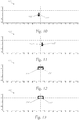
- FIG. 10 to 27 show different light distributions, with in Figures 14 and 15 Intensities of the Isolux curves are shown as examples, their intensity amounts for all Figures 10 to 27 be valid.
- an intensity maximum is in accordance with a line projection Fig. 18 with approx. 78k candela about twice as large as the intensity maximum of an area lighting of a low beam with approx. 40 k candela according to Fig. 14 . So that the driver has a contrast of a projected line versus one In front of the area lighting, that is, a switched-on low beam light function of the vehicle, can detect, such an intensity difference is necessary.
- the light intensities used by way of example can be converted into illuminance intensities, as is familiar to the person skilled in the art.
- Fig. 1 an overview of a vehicle 1 is shown, which has left and right main headlights 2 'and 2 "and auxiliary headlights 3' and 3" according to the invention.
- the two main headlights 2 ', 2 preferably produce a light distribution of low beam or high beam.
- the two additional headlights 3', 3" according to the invention produce a linear light distribution as well as a light distribution of an additional high beam in two modules, whereby all light distributions can be activated individually or in combination of the headlights , as well as the combination of left and right headlights is possible to take into account the respective driving situation.
- the position of the individual headlights 2 ', 2 ", 3' and 3" on the vehicle 1 can vary and depends, among other things, on the design of the vehicle. A position of the auxiliary headlights 2 ', 2 "according to the invention on the vehicle 1 close to the roadway can be advantageous.
- a headlight system 4 which comprises a main headlight 2 ', 2 "and an additional headlight 3', 3".
- a light image 110 ', 110 "of the auxiliary headlight 3', 3” can be superimposed by a further light image 210 ', 210 ", 220', 220" of the main headlight 2 ', 2 " left and right additional headlights 3 ', 3 "and left and right main headlights 2', 2".
- the left and right additional headlights 3 ', 3 " can each project different light images.
- the light image of the main headlight 2 ', 2 " can be a light image of a low beam 210', 210" or a high beam 220 ', 220 ".
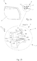
- FIG. 2a the arrangement of the additional headlights 3 ', 3 "as additional headlights 3 is shown in overview.
- the additional headlight 3 consists of a light module 5 that emits the light, forms it and projects it in front of the vehicle as a light image 110', 110" through downstream imaging optics 8.
- Detail A in Figure 2b shows the light module 5, which comprises a first light module 6 for generating first light emissions by first light sources 9a and 9b, as well as a second light module 7 for generating second light emissions by second light sources 10a, 10b, 10c and a primary optics 11.
- the primary optics 11 of the Auxiliary headlight 3 comprises two parts, a first primary lens 11a of the first light module and a second primary lens 11b of the second light module and has a plurality of light guide elements 12a, 12b, 13a, 13b, 13c, with each light guide element 12a, 12b, 13a, 13b, 13c has a light entry surface 14 for coupling in a light emission, as well as a light exit surface 15.
- the light guide elements 12a, 12b, 13a, 13b, 13c of the primary optics form two groups for two different light distributions, which are represented by the light modules 6 and 7 with the associated light sources. The structural separation of the two light modules serves to decouple the optical propagation paths.
- the first light emission couples into a first light guide element 12a, 12b of the primary optics 11 and the second light emission couples into a second light guide element 13a, 13b, 13c of the primary optics 11.
- the light sources 9a, 9b, 10a, 10b, 10c can be coupled loosely or firmly to the respective light entry surfaces.
- the type of coupling mentioned is determined, among other things, by the design of the light sources 9a, 9b, 10a, 10b, 10c, whereby a spacing between light entry surfaces and light sources can be structurally provided in order to counter mechanical loads, such as vibrations or different temperature expansions of individual components to be able to.
- Light guide elements 12a, 12b, 13a, 13b, 13c form together with a diaphragm 16, which comprises diaphragm openings 16a, 16b (not shown in this figure) the light emissions and form a luminous image on the common surface F, which is the Petzval surface of the Imaging optics 8 reshaped.
- the diaphragm 16, through its diaphragm openings 16a, 16b, usually ensures sharp contours in the luminous image, while the light guide elements 12a, 12b, 13a, 13b, 13c provide suitable flat emission characteristics.
- the cross section of the light guide elements 12a, 12b, 13a, 13b, 13c usually increases from the light entry surface 14 to the light exit surface 15. Consequently, the light exit surfaces 15 are larger than the corresponding light entry surfaces 14 of the respective light guide element 12a, 12b, 13a, 13b, 13c.
- the light exit surfaces 14 of all light guide elements 12a, 12b, 13a, 13b, 13c preferably lie in an area F. It is favorable if the area F is a plane and thus allows a particularly simple construction of the primary optics 11. In addition, it is advantageous if the light exit surfaces of all light guide elements 12a, 12b, 13a, 13b, 13c, which are assigned to the same light module 6, 7, have a common light exit surface and all light guide elements of the first light module 6, from those of the second light module 7, are structurally separated in order to reduce cross-coupling between the two light modules 6 and 7. This is very important for high efficiency of the auxiliary headlight 3, since the light emission generated should be transformed into the desired light distribution with as little loss as possible.
- the primary optics 11 can be made of an elastic (e.g. silicone, photopolymers, etc.) or solid (e.g. polycarbonate, thermoplastics, photopolymers, glass, etc.) material, the particular choice being determined by commercial requirements.
- the primary optics are particularly easy to manufacture using an injection molding process.
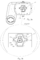
- Fig. 3a shows the additional headlight 3 with a holder 17 for mechanical fastening of the light modules 6 and 7 in the additional headlight 3, without a mounted cover and without imaging optics 8.
- B in Figure 3b is the position of the first light module 6 for generating the linear intensity maximum 8a by the associated light guide elements 12a, 12b and of the second light module 7 for generating the rectangular intensity maximum 122 ', 122 "by the associated light guide elements 13a, 13b, 13c in the light distribution.
- an axis of rotation D is shown, about which the auxiliary headlight 3 can be pivoted mechanically in order to enable the light distributions generated to be tracked following the course of the road.
- a second axis of rotation for pivoting about a further, for example horizontal, axis is not shown.
- the holder 17 is made in one piece here in order to fix the light guide elements of the primary optics 11. As a result, only a common fastening is necessary and design, manufacture, assembly, etc. are simplified.
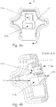
- FIGs 4a and 4b the light modules 6 and 7 or the two-part primary optics 11, which are held in position with a holder 17, are shown in each case.
- the holder can be made of an elastic or solid material, with structural reinforcements only being advantageous in the area around the light guide elements 12a, 12b, 13a, 13b, 13c and the edge area of the holder 17 in order to keep the weight of the holder 17 as low as possible .
- the light sources 9a, 9b, 10a, 10b, 10c themselves are mostly held by a circuit board (not shown).
- Fig. 5 shows the light module 6, 7 in a front view with a mounted screen 13, which has two screen openings 16a, 16b in order to shape the light emission in addition to the light guide elements 12a, 12b, 13a, 13b, 13c.
- the diaphragm 16 creates particularly sharp contours in the light distribution, which is essential, for example, for line projection and its visibility through good contrast.
- the common screen 16 allows, among other things, a cost-effective and simple design, manufacture or assembly and supports the compact and lightweight design of the auxiliary headlight.
- the cover 16 is fastened by one or more mounting points 20 in the additional headlight 3, the installation points 20 being particularly advantageously designed as bores through which screws connect the cover to another part of the additional headlight 3.
- the bracket 17 is designed in such a way that it has recesses at the positions of the screw connections in order to support a common fastening by the aforementioned screws of the cover 16 with a housing of the auxiliary headlight 3 with the bracket 17 in between, the screws forming the cover 16 connect to the housing of the auxiliary headlight 3 and a cooling device 18 can be part of the housing.
- the assembly consequently proves to be particularly simple and quick, and the number of components required for the additional headlight 3 is kept to a minimum.
- the use of four screws is advantageous, as this achieves particular stability and freedom from distortion due to mechanical or thermal loading forces. Screws as a detachable connection have particularly favorable properties with regard to maintenance. Furthermore, the structure is particularly simple if a circuit board 21 (not shown) is inserted into the combination of a cover 16, a holder 17 and a housing of the auxiliary headlight 3, which includes at least several light sources 9a, 9b, 10a, 10b, 10c and is fixed by the same fastening, wherein the circuit board 21 or the light sources 9a, 9b, 10a, 10b, 10c arranged thereon is thermally well connected to the housing.
- Fig. 6 shows the light module 6, 7 in a perspective view with the mounted screen 16 and the screen openings 16a, 16b.
- Fig. 7 shows the very compact additional headlight 3 in the front view, on which the imaging optics 8 is placed.
- the axis of rotation D can be seen, about which the auxiliary headlight 3 can be pivoted mechanically.
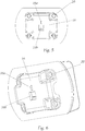
- Fig. 8 shows the auxiliary headlight 3 in a view from behind with the common cooling device 18 for the light module 6, 7 located on the rear.
- the common cooling device 18 can be small, light and designed to be inexpensive.
- the additional headlight 3 can be pivoted about the axis of rotation D.
- the common control device 19, which electrically controls the two light modules 6 and 7, is not shown.
- the common control device 19 achieves cost and weight advantages.
- Fig. 9 shows the auxiliary headlight 3 in the exploded view with imaging optics 8 and holder 17 and circuit board 21 with light sources 9a, 9b, 10a, 10b, 10c (not shown).
- the holder 17 can be made of an elastic or rigid material.
- the common holder 17 for the two-part primary optics 11 supports a simple construction or assembly, and a compact design of the additional headlight is achieved.
- the circuit board 21 can usually include further electronic circuits such as driver and logic stages for switching the light sources 9a, 9b, 10a, 10b, 10c or the control device, as well as connection units for connecting to cables for control and power supply.
- the joint design of the connection units for both light modules is advantageous in order to keep the cable harness in the vehicle simple.
- the circuit board 21 can be designed in such a way that it supports a suitable thermal connection between light sources 10 and cooling device 18, for example through openings in the circuit board 21.
- the optical radiating surface of the light source 10 is equipped with special cooling contacts in order to enable a favorable connection to a heat sink.
- the cooling by the cooling device 18 can be active, that is to say by a fan for air cooling or a liquid cooling, in the present example the cooling device 18 is a passive heat sink.
- FIGS. 10 to 27 show photos in Cartesian representation with angular scales on both axes according to the UN ECE guidelines for uniform conditions for approval of motor vehicle headlights (e.g. TRANS / WP.29 / 343), which represent isolux lines for different intensities.
- TRANS / WP.29 / 343 represent isolux lines for different intensities.
- a left main headlight is designated below with the reference number 2 'and a right main headlight is designated with the reference number 2 ", the main headlights typically having the same design, but being constructed symmetrically about the longitudinal axis of the vehicle.
- the left auxiliary headlight 3 ' which is structurally, for example, an auxiliary headlight 3 according to FIG Figures 1 to 9 can, for example, generate a light image 110 'through a first left light module 6', which structurally corresponds to the first light module 6 ( Fig. 10 ).
- the right auxiliary headlight 3 ′′ which is structurally for example an auxiliary headlight 3 according to FIG Figures 1 to 9 can generate a light image 110 ", for example, by means of a first right light module 6", which structurally corresponds to the first light module 6 ( Fig. 11 ).
- the light images 110 'and 110 " can each have line light distributions 111', 111" with linear intensity maxima 112 'and 112 ".
- the light distributions shown are partially formed by superimposing several light distributions. Consequently, for example, the intensity maxima shown are, strictly speaking, a superposition of an individual intensity maximum with a further light distribution at the location of the maximum, whereby the respective function value no longer corresponds exactly to the original intensity maximum at that location.
- this aspect is not taken into account and is not shown separately in the figures. This aspect is to be used in principle and therefore also for the light distributions in the other figures.
- the left and right main headlights 2 ', 2 include light functions for a low beam 210', 210" and a high beam 220 ', 220 ".
- Fig. 10 shows the light image 110 'of the left auxiliary headlight 3' with its first light distribution 111 'and its first, linear intensity maximum 112', ie a line light distribution.
- Fig. 11 shows the light image 110 ′′ of the right auxiliary headlight 3 ′′ with its first light distribution 111 ′′ and its first, linear intensity maximum 112 ′′, ie a line light distribution.
- Fig. 12 shows the light image 120 'of the left auxiliary headlight 3' with its second light distribution 121 'and its second, essentially rectangular intensity maximum 122', ie an additional high beam light distribution.
- the essentially rectangular intensity maximum 122 ′ can be square, rectangular, trapezoidal or else elliptical, for example, and have pointed or rounded corners. Special forms of the intensity maximum 122 'are also conceivable in order to obtain the best possible light distribution depending on the traffic situation.
- a dynamic form of the intensity maximum 122 ' which is actively adapted, for example, to the respective traffic situation, is also possible. This dynamic adaptation can mean the targeted switching off of individual areas within the intensity maximum 122 'in order to obtain a glare-free high beam and to fade out the oncoming traffic at certain points.
- Fig. 13 shows the light image 120 ′′ of the right auxiliary headlight 3 ′′ with its second light distribution 121 ′′ and its second, essentially rectangular intensity maximum 122 ′′, for example an additional high beam light distribution.
- a light image 210 'of a light distribution 211' of a low beam of the left main headlight 2 ' is shown with a typical asymmetry in the cut-off line.
- Fig. 15 shows the photo 110 'of the left auxiliary headlight 3' with the linear light distribution 111 ' Fig. 10 , which the light image 210 'the low beam light distribution 211' of the left main headlight 2 'after Fig. 14 is superimposed.
- the intensity maximum 112 ' is approximately twice as large with approx. 78 k candela as the intensity maximum with approx. 40 k candela according to a front area lighting or a low beam Fig. 14 .
- Fig. 16 shows the light image 110 "of the right auxiliary headlight 3" with the linear light distribution 111 "with the maximum intensity 112" Fig. 11 , on which the light image 210 ′′ with the low beam light distribution 211 ′′ of the right main headlight 2 ′′ is superimposed.
- Fig. 17 shows the superimposed overall light image of the light images 110 ', 110 " Figures 15 and 16 of the left and right auxiliary headlights 3 ', 3 "with linear intensity maxima 112', 112" in the respective light distribution 111 ', 111 ", as well as the light images 210', 210" of the light distributions 211 ', 211 "of the left and right main headlight 2' , 2 "each with a low beam light distribution.
- Fig. 18 simulates the overall light distribution Fig. 17 as a light image by projection onto the roadway in front of the vehicle 1. Compared to the aforementioned light images, the projection view contains perspective image distortions.
- a light image 220 ′′ of a high beam light distribution 221 ′′ of the right main headlight 2 ′′ is shown.
- Fig. 21 shows the light image 220 'with the high beam light distribution 221' of the left main headlight 2 'together with the additional high beam light distribution 121' and the maximum intensity 122 'of the left auxiliary headlight 3'.
- Fig. 22 shows the light image 220 "with the high beam light distribution 221" of the right main headlight 2 "together with the light image 120" of the additional high beam light distribution 121 “and the maximum intensity 122" of the right auxiliary headlight 3 ".
- Fig. 23 simulates a light distribution Fig. 22 as a photograph by projection onto the roadway in front of vehicle 1.
- Fig. 24 shows the light image 220 'with the high beam light distribution 221' of the left main headlight 2 'together with the light image 120' of the additional high beam light distribution 121 'and the light image 110' with the line light distribution 111 'of the left auxiliary headlight 3'.
- Fig. 25 shows the photo 220 "with the high beam light distribution 221" of the right main headlight 2 "together with the photo 120" of the additional high beam light distribution 121 “and the photo 110" with the line light distribution 111 "of the right auxiliary headlight 3".
- Fig. 26 shows an overall light image of the light images 110 ', 120', 110 “, 120” of a superimposed overall light distribution of the left and right auxiliary headlights 3 ', 3 "with linear intensity maxima 112', 112" in the respective light distribution 111 ', 111 "together with the respective Additional high beam light distribution 121 ', 121 "and the respective intensity maximum 122', 122 ', as well as the left and right main headlights 2', 2" each with a light image 220 ', 220 "which comprises a high beam light distribution 221', 221” .
Landscapes
- Engineering & Computer Science (AREA)
- General Engineering & Computer Science (AREA)
- Mechanical Engineering (AREA)
- Physics & Mathematics (AREA)
- Microelectronics & Electronic Packaging (AREA)
- Optics & Photonics (AREA)
- Lighting Device Outwards From Vehicle And Optical Signal (AREA)
- Non-Portable Lighting Devices Or Systems Thereof (AREA)
Description
Die Erfindung betrifft einen Zusatzscheinwerfer für ein Fahrzeug, der dazu eingerichtet ist, ein Lichtbild vor dem Fahrzeug durch Emittieren von Licht aus zumindest einem Lichtmodul zu erzeugen und durch eine nachgelagerte Abbildungsoptik vor das Fahrzeug zu projizieren.The invention relates to an additional headlight for a vehicle which is set up to generate a light image in front of the vehicle by emitting light from at least one light module and to project it in front of the vehicle through a downstream imaging optics.
Bei der Entwicklung der gegenwärtigen Scheinwerfersysteme steht immer mehr der Wunsch im Vordergrund, ein Lichtbild auf die Fahrbahn projizieren zu können, das rasch geändert und den jeweiligen Verkehrs-, Straßen- und Lichtbedingungen angepasst werden kann. Dazu werden verschiedene Scheinwerfer, beispielsweise Haupt- und Zusatzscheinwerfer, eingesetzt, die unterschiedliche Lichtbilder auf der Fahrbahn erzeugen. Der Begriff "Fahrbahn" wird hier zur vereinfachten Darstellung verwendet, denn selbstverständlich hängt es von den örtlichen Gegebenheiten ab, ob sich ein Lichtbild tatsächlich auf der Fahrbahn befindet oder auch darüber hinaus erstreckt. Prinzipiell entspricht das Lichtbild im verwendeten Sinn einer Projektion auf eine vertikale Fläche entsprechend der einschlägigen Normen, die sich auf die KFZ-Beleuchtungstechnik beziehen.In the development of current headlight systems, the focus is increasingly on the desire to be able to project a light image onto the roadway that can be quickly changed and adapted to the respective traffic, road and light conditions. For this purpose, different headlights, for example main and auxiliary headlights, are used, which generate different light images on the roadway. The term “roadway” is used here for a simplified representation, because of course it depends on the local conditions whether a photograph is actually located on the roadway or whether it extends beyond it. In principle, the light image in the sense used corresponds to a projection onto a vertical surface in accordance with the relevant standards that relate to vehicle lighting technology.
Um diesem genannten Bedürfnis zu entsprechen, wurden unter anderem Scheinwerfer entwickelt, die aus einer Mehrzahl von Einzelstrahlern eine Leuchtmatrix bilden. Derartige Leuchteinrichtungen sind im Fahrzeugbau gebräuchlich und dienen beispielsweise der Abbildung von blendfreiem Fernlicht, indem das Licht in der Regel von einer Mehrzahl von Lichtquellen ausgestrahlt wird und von einer entsprechenden Mehrzahl von nebeneinander angeordneten Lichtführungen (Vorsatzoptik/ Primäroptik) in Abstrahlrichtung gebündelt wird. Die Lichtführungen weisen einen relativ geringen, trichterförmigen Querschnitt auf und senden das Licht der ihnen zugeordneten einzelnen Lichtquellen daher sehr konzentriert in die Abstrahlrichtung aus. Die Lichtführungen leiten das Licht von den Lichtquellen zu einer möglichst gut angenäherten Position auf einer räumlich gekrümmten Ebene, der Petzval-Fläche der vorgelagerten Abbildungsoptik, weiter. Jedoch weist diese Art von Matrix-Scheinwerfern insbesondere bei Verwendung von einer größeren Anzahl von Hochleistungs-Lichtquellen Einschränkungen in Bezug auf Ableitung deren thermischer Verlustleistung auf. Folglich sind Scheinwerfer, die dynamische Lichtbilder mit besonders hoher Intensität erzeugen, nur sehr aufwendig herzustellen.In order to meet this need, headlights were developed, among other things, which form a light matrix from a plurality of individual spotlights. Such lighting devices are common in vehicle construction and are used, for example, to display glare-free high beam, in that the light is usually emitted by a plurality of light sources and is bundled in the direction of emission by a corresponding plurality of light guides arranged next to one another (front optics / primary optics). The light guides have a relatively small, funnel-shaped cross section and therefore emit the light from the individual light sources assigned to them in a very concentrated manner in the direction of emission. The light guides guide the light from the light sources to a position that is as closely approximated as possible on a spatially curved plane, the Petzval surface of the upstream imaging optics. However, this type of matrix headlights has limitations with regard to the dissipation of their thermal power loss, particularly when a larger number of high-power light sources are used. As a result, headlights that generate dynamic light images with particularly high intensity are very expensive to manufacture.
Unterschiedliche Verkehrssituationen stellen jeweils voneinander verschiedene spezifische Anforderungen an die Scheinwerfer eines Fahrzeugs. Es kann neben der Ausleuchtung der Fahrbahn durch ein Abblendlicht oder Fernlicht auch gewünscht sein, den Fahrer auf spezielle Gefahrensituationen durch geeignete optische Signalisierung aufmerksam zu machen. Eine solche Gefahrensituation stellt beispielsweise eine Fahrbahnverengung durch eine Baustelle dar. Viele Fahrer können den Abstand zwischen Fahrzeug und Fahrbahnbegrenzung nur schwer einschätzen, da der Fahrer keine direkte Sicht aus der Fahrerperspektive auf die Fahrbahnbegrenzung wie auch auf die Außenbegrenzung des Fahrzeugs hat. Zu diesem Zweck wurde bereits die Funktion eines "Optical Lane Assist" vorgeschlagen.Different traffic situations place different specific requirements on the headlights of a vehicle. In addition to illuminating the lane with dipped or high beam, it may also be desirable to draw the driver's attention to special dangerous situations by means of suitable optical signaling. Such a dangerous situation is, for example, a narrowing of the lane due to a construction site. Many drivers find it difficult to assess the distance between the vehicle and the lane boundary, since the driver does not have a direct view of the lane boundary or the outer boundary of the vehicle from the driver's perspective. The function of an "Optical Lane Assist" has already been proposed for this purpose.
Die
Eine Aufgabe der vorliegenden Erfindung liegt darin, eine einfache, kompakte und kostengünstige Ausführungsform für einen Linienscheinwerfer zu finden.One object of the present invention is to find a simple, compact and inexpensive embodiment for a line headlight.
Diese Aufgabe wird mit einem Zusatzscheinwerfer der eingangs genannten Art derart gelöst, dass erfindungsgemäß die Funktion eines Zusatzfernlichts mit der Funktion eines Linienlichts kombiniert wird, um durch die Realisierung in einem gemeinsamen Bauteil eine sehr kompakte Bauform zu erreichen und dadurch Kostenvorteile zu gewinnen. Somit wird ein Zusatzscheinwerfer der eingangs genannten Art derart verbessert, dass
- ein erstes Lichtmodul dazu eingerichtet ist, ein erstes Lichtbild mit zumindest einer ersten Lichtverteilung mit zumindest einem ersten, im Wesentlichen vertikal orientierten, linienförmigen Intensitätsmaximum zu erzeugen, und
- ein zweites Lichtmodul dazu eingerichtet ist, ein zweites Lichtbild mit einer zweiten Lichtverteilung mit zumindest einem zweiten, im Wesentlichen rechteckförmigen Intensitätsmaximum zu erzeugen,
- und sich die Lichtbilder beider Lichtmodule überlagern, wobei das erste Intensitätsmaximum vertikal unter dem zweiten Intensitätsmaximum gelegen ist.
- a first light module is set up to generate a first light image with at least one first light distribution with at least one first, essentially vertically oriented, linear intensity maximum, and
- a second light module is set up to generate a second light image with a second light distribution with at least one second, essentially rectangular intensity maximum,
- and the light images of the two light modules are superimposed, the first intensity maximum being located vertically below the second intensity maximum.
Speziell bei der Integration von mehreren Leuchtvorrichtungen mit ähnlichen Leuchteigenschaften in ein gemeinsames Bauteil vergrößert sich der erzielte Vorteil deutlich. Erfindungsgemäß wird ein Zusatzfernlicht mit einem Linienlicht in einem Bauteil kombiniert, wobei beide Leuchtvorrichtungen jeweils hohe Lichtleistung mit starker optischer Bündelung, d.h. mit kleiner Apertur aufweisen. Vorteilhaft sind daher unter anderem die einfache, kombinierte Ausführung der Projektionslinse, sowie die gemeinsame Kühlung bzw. elektrische Ansteuerung beider Leistungslichtquellen. Der Zusammenbau des Scheinwerfers vereinfacht sich unter anderem durch eine gemeinsame Primäroptik und Blende, die reduzierte Zahl von Montagevorrichtungen äußert sich in geringeren Materialkosten, kleinerer Baugröße und verkürzter Montagezeit.Especially when integrating several lighting devices with similar lighting properties in a common component, the advantage achieved is significantly increased. According to the invention, an additional high beam is combined with a line light in one component, both lighting devices each having a high light output with strong optical focus, i.e. with a small aperture. Therefore, among other things, the simple, combined design of the projection lens and the common cooling or electrical control of both power light sources are advantageous. The assembly of the headlight is simplified, among other things, by a common primary optics and cover, the reduced number of assembly devices is expressed in lower material costs, smaller size and shorter assembly time.
Die gesamte Projektionsanordnung besteht aus Lichtquelle, Primäroptik und einer Abbildungsoptik (Projektionslinse). Die Abbildungsoptik kann je nach Ausführung zu Verzeichnungen führen. Die Verzeichnung ist ein geometrischer Abbildungsfehler optischer Systeme, der zu einer lokalen Veränderung des Abbildungsmaßstabes führt. Die Maßstabsänderung beruht auf einer Änderung der Vergrößerung mit zunehmendem Abstand des Bildpunktes von der optischen Achse. Die Verzeichnung ist daher rotationssymmetrisch um einen Punkt, der auch Verzeichnungszentrum genannt wird. Die Ursache der Verzeichnung liegt an Blenden, die das Strahlenbündel der Abbildung vor oder hinter der Hauptebene eines optischen Systems mit Öffnungsfehler einengen. Nimmt die Vergrößerung zu den Rändern des Bildfelds zu, dann wird ein Quadrat kissenförmig verzeichnet. Im umgekehrten Fall spricht man von tonnenförmiger Verzeichnung. Es können auch Verzeichnungen höherer Ordnung auftreten, und die Überlagerung verschiedener Ordnungen kann zu einer wellenförmigen Abbildung gerader Linien führen ("wellenförmige Verzeichnung"). Das Maß der Verzeichnung ist bekannt nach DIN ISO 9039: Optik und Photonik - Qualitätsbewertung optischer Systeme - Bestimmung der Verzeichnung (ISO 9039:2008).The entire projection arrangement consists of a light source, primary optics and imaging optics (projection lens). The imaging optics can lead to distortions depending on the version. Distortion is a geometric aberration in optical systems that leads to a local change in the image scale. The change in scale is based on a change in magnification as the distance between the image point and the optical axis increases. The distortion is therefore rotationally symmetrical around a point, which is also called the center of the distortion. The cause of the distortion is due to apertures that narrow the beam of the image in front of or behind the main plane of an optical system with aperture errors. If the magnification increases towards the edges of the image field, a square is drawn in the shape of a pillow. In the opposite case one speaks of barrel-shaped distortion. Distortions of a higher order can also occur, and the superposition of different orders can lead to a wavy image of straight lines ("undulating distortion"). The degree of distortion is known according to DIN ISO 9039: Optics and photonics - Quality assessment of optical systems - Determination of distortion (ISO 9039: 2008).
Es ist auch klar, dass es bei der Projektion eines Lichtbildes auf die Fahrbahn vor das Fahrzeug zu Projektionsverzerrungen kommen kann, beispielsweise kann ein Lichtbild trapezförmig verzerrt auf der Fahrbahn erscheinen, da die Projektionsebene nicht normal zur Abstrahlrichtung des Lichts orientiert ist. Diese Projektionsverzerrungen entstehen zusätzlich zu den vorher genannten Verzeichnungen.It is also clear that projection distortions can occur when a light image is projected onto the roadway in front of the vehicle, for example a light image can appear distorted in a trapezoidal shape on the roadway because the projection plane is not oriented normally to the direction of the light. These projection distortions arise in addition to the previously mentioned distortions.
Sowohl Projektionsverzerrungen als auch Verzeichnungen können durch eine entsprechende Vorverzerrung reduziert bzw. kompensiert werden.Both projection distortions and distortions can be reduced or compensated for by a corresponding predistortion.
Günstig ist es daher, wenn bei der Erzeugung der Lichtverteilungen im Scheinwerfer eine Vorverzerrung durchgeführt ist, beispielsweise durch eine Blende, und als Ergebnis ein insgesamt entzerrtes Lichtbild projiziert oder zumindest eine Reduktion des störenden Effekts erzielt ist.It is therefore beneficial if, when generating the light distributions in the headlight, a predistortion is carried out, for example by means of a diaphragm, and as a result an overall rectified light image is projected or at least a reduction in the disruptive effect is achieved.
Mit dem ersten, im Wesentlichen vertikal orientierten, linienförmigen Intensitätsmaximum ist folglich die entzerrte Lichtprojektion gemeint, in der Projektionsverzerrungen und/ oder Verzeichnungen reduziert sind, gegebenenfalls auch um einer perspektivischen Darstellung der projizierten Linie mit einem Fluchtpunkt in Fahrrichtung oder im Straßenverlauf zur realistischen Darstellung mit Zentralprojektion Rechnung zu tragen. Eine gewisse Linienbreite in der Projektion ist vorgesehen, sodass die projizierte Linie des Fahrzeug-Assistenzsystems aus der Fahrerperspektive gut erkennbar ist.The first, essentially vertically oriented, linear intensity maximum consequently means the rectified light projection, in which projection distortions and / or distortions are reduced, possibly also by a perspective representation of the projected line with a vanishing point in the direction of travel or in the course of the road for realistic representation with central projection To take into account. A certain line width is provided in the projection so that the projected line of the vehicle assistance system can be easily recognized from the driver's perspective.
Es ist vorteilhaft, wenn die langen Seiten des im Wesentlichen rechteckförmigen Intensitätsmaximums horizontal orientiert sind, um eine günstige Lichtverteilung für ein Zusatzfernlicht zu erhalten.It is advantageous if the long sides of the essentially rectangular intensity maximum are oriented horizontally in order to obtain a favorable light distribution for an additional high beam.
Bei einer bevorzugten Ausführungsform liegt das erste Intensitätsmaximums horizontal innerhalb der horizontalen Breite des zweiten Intensitätsmaximums. Durch den geringen Abstand beider Intensitätsmaxima ist die Apertur der gesamten Optik klein und eine besonders kleine, kompakte und kostengünstige Bauform wird erreicht.In a preferred embodiment, the first intensity maximum lies horizontally within the horizontal width of the second intensity maximum. Due to the small distance between the two intensity maxima, the aperture of the entire optics is small and a particularly small, compact and inexpensive design is achieved.
Eine weitere bevorzugte Ausführung des Zusatzscheinwerfers sieht vor, dass das erste Intensitätsmaximum und das zweite Intensitätsmaximum mit einem vertikalen Abstand zueinander angeordnet sind. Beide Lichtverteilungen des Zusatzscheinwerfers haben zwar ähnliche Leuchteigenschaften, dienen vorzugsweise aber unterschiedlichen Anwendungen im Nah- bzw. Fernbereich vor dem Fahrzeug. Das Linienlicht des ersten Lichtmoduls projiziert bevorzugt im Bereich von 2 bis 20 Meter vor dem Fahrzeug eine Linie auf die Fahrbahn, das Zusatzfernlicht des zweiten Lichtmoduls projiziert im Fernlichtbereich, d.h. vorzugsweise im Abstand von mehr als 50 Meter ein Rechteck zur Unterstützung eines weiteren Fernlichts. Aus diesem Grund ist es vorteilhaft, wenn beide Lichtverteilungen keine Überlappung in ihren Intensitätsmaxima aufweisen.Another preferred embodiment of the additional headlight provides that the first intensity maximum and the second intensity maximum are arranged at a vertical distance from one another. Both light distributions of the auxiliary headlight have similar lighting properties, but are preferably used for different applications in the near and far range in front of the vehicle. The line light of the first light module projects a line onto the roadway preferably in the area of 2 to 20 meters in front of the vehicle, the additional high beam of the second light module projects in the high beam area, ie preferably at a distance of more than 50 meters a rectangle to support a further high beam. For this reason, it is advantageous if the two light distributions do not have any overlap in their intensity maxima.
Erfindungsgemäß kann das erste und zweite Lichtbild gleichzeitig oder alternativ projiziert sein und die elektrischen bzw. thermischen Systemanteile demgemäß ausgelegt werden. Wird beispielsweise festgelegt, dass entweder nur Linienlicht oder nur Zusatzfernlicht aktiv sind, vorzugsweise abhängig von der Geschwindigkeit des Fahrzeugs, so kann die gemeinsame Kühlvorrichtung kleiner und kostengünstiger ausgelegt werden. Es kann sowohl eine aktive als auch eine passive Kühlvorrichtung eingesetzt werden.According to the invention, the first and second light image can be projected simultaneously or alternatively and the electrical or thermal system components can be designed accordingly. If, for example, it is specified that either only line light or only additional high beam are active, preferably depending on the speed of the vehicle, then the common cooling device can be designed to be smaller and more cost-effective. Both an active and a passive cooling device can be used.
Erfindungsgemäß umfasst der Zusatzscheinwerfer:
- zumindest ein erstes Lichtmodul zur Erzeugung einer ersten Lichtemission durch zumindest eine erste Lichtquelle,
- zumindest ein zweites Lichtmodul zur Erzeugung einer zweiten Lichtemission durch zumindest eine zweite Lichtquelle,
- zumindest eine Primäroptik, wobei die Primäroptik eine Mehrzahl von Lichtführungselementen aufweist und jedes Lichtführungselement eine Lichteintrittsfläche zum Einkoppeln einer Lichtemission, sowie eine Lichtaustrittsfläche aufweist,
- wobei die erste Lichtemission in zumindest ein erstes Lichtführungselement der Primäroptik einkoppelt, die zweite Lichtemission in zumindest ein zweites Lichtführungselement der Primäroptik einkoppelt,
- zumindest eine der Primäroptik nachgelagerte Blende mit zumindest einer ersten Blendenöffnung, die der Lichtaustrittsfläche des ersten Lichtführungselements zugewandt ist und zumindest einer zweiten Blendenöffnung, die der Lichtaustrittsfläche des zweiten Lichtführungselements zugewandt ist, wobei die Primäroptik und die Blende ein Gesamtleuchtbild aus den Lichtemissionen erzeugen und
- eine der Blende nachgelagerte Abbildungsoptik das Gesamtleuchtbild als Lichtbild in Abstrahlrichtung des Zusatzscheinwerfers als Gesamtlichtbild projiziert.
- at least one first light module for generating a first light emission by at least one first light source,
- at least one second light module for generating a second light emission by at least one second light source,
- at least one primary optics, wherein the primary optics have a plurality of light guide elements and each light guide element has a light entry surface for coupling in a light emission, as well as a light exit surface,
- wherein the first light emission couples into at least one first light guide element of the primary optics, the second light emission couples into at least one second light guide element of the primary optics,
- at least one diaphragm downstream of the primary optics with at least one first diaphragm opening facing the light exit surface of the first light guide element and at least one second diaphragm opening facing the light exit surface of the second light guide element, the primary optics and the diaphragm generating an overall luminous image from the light emissions and
- an imaging optics downstream of the diaphragm projects the overall luminous image as a light image in the direction of emission of the auxiliary headlight as an overall light image.
Durch genannte Anordnung wird ein besonders kostengünstiger Zusatzscheinwerfer geschaffen, der die gewünschten Lichtverteilungen in Einbaulage des Fahrzeugs erzeugt und der bei dessen Zusammenbau durch eine gemeinsame Primäroptik und Blende die Anzahl von Montagevorrichtungen verringert, und Herstellung in Form von geringeren Materialkosten, kleinerer Baugröße und verkürzter Montagezeit deutlich verbessert.The above-mentioned arrangement creates a particularly cost-effective auxiliary headlamp that generates the desired light distribution in the installation position of the vehicle and that when it is assembled by means of a common primary optics and panel reduces the number of assembly devices, and production in the form of lower material costs, smaller size and shorter assembly time improved.
Besonders günstig ist es, wenn dabei alle Lichtaustrittsflächen aller Lichtführungselemente in einer Fläche liegen, da die Konstruktion dadurch vereinfacht wird.It is particularly favorable if all the light exit surfaces of all light guide elements lie in one surface, since this simplifies the construction.
Zusätzlich wird die Konstruktion vereinfacht, wenn die Lichtaustrittsflächen aller Lichtführungselemente, die demselben Lichtmodul zugeordnet sind, eine gemeinsame Lichtaustrittsfläche ausbilden.In addition, the construction is simplified if the light exit surfaces of all light guide elements that are assigned to the same light module form a common light exit surface.
Eine effiziente Ausführung beider Lichtmodule sieht vor, dass das alle Lichtführungselemente des ersten Lichtmoduls, von jenen des zweiten Lichtmoduls, baulich getrennt sind, um beide Lichtmodule funktional zu entkoppeln und unerwünschte Lichteinkopplung vom jeweils anderen Lichtmodul zu reduzieren.An efficient design of both light modules provides that all light guide elements of the first light module are structurally separated from those of the second light module in order to functionally decouple both light modules and to reduce unwanted light coupling from the other light module.
Zu weiteren Vereinfachung der Konstruktion und zur Reduktion der Herstellkosten ist für alle Lichtführungselemente eine gemeinsame Halterung vorgesehen.To further simplify the construction and to reduce the manufacturing costs, a common holder is provided for all light guide elements.
In einer besonders günstigen Variante wird die Lichtleistung des ersten Lichtmoduls derart verbessert, dass das erste Lichtmodul eine Mehrzahl von Lichtquellen umfasst, die im Wesentlichen vertikal in einer Reihe übereinander angeordnet sind.In a particularly favorable variant, the light output of the first light module is improved in such a way that the first light module comprises a plurality of light sources which are arranged essentially vertically in a row one above the other.
In einer weiteren, besonders günstigen Variante wird die Lichtleistung des zweiten Lichtmoduls derart verbessert, dass das zweite Lichtmodul eine Mehrzahl von Lichtquellen umfasst, die im Wesentlichen horizontal in einer Reihe nebeneinander angeordnet sind.In a further, particularly favorable variant, the light output of the second light module is improved in such a way that the second light module comprises a plurality of light sources which are arranged essentially horizontally in a row next to one another.
Da die Abbildungsoptik die Orientierung des Lichtbildes bei der Projektion invertiert, ist es vorteilhaft, diesen Umstand in der Anordnung der Lichtmodule zu berücksichtigen, indem das erste Lichtmodul über dem zweiten Lichtmodul angeordnet ist.Since the imaging optics inverts the orientation of the light image during projection, it is advantageous to take this fact into account in the arrangement of the light modules by arranging the first light module above the second light module.
Eine kostengünstige Kühlung lässt sich konstruktiv besonders gut umsetzen, wenn das erste Lichtmodul und das zweite Lichtmodul benachbart liegen und eine gemeinsame Kühleinrichtung nutzen.In terms of construction, inexpensive cooling can be implemented particularly well if the first light module and the second light module are adjacent and use a common cooling device.
Eine kostengünstige Steuereinrichtung lässt sich konstruktiv besonders gut umsetzen, wenn das erste Lichtmodul und das zweite Lichtmodul von einer gemeinsamen Steuereinrichtung angesteuert werden.An inexpensive control device can be implemented particularly well in terms of design if the first light module and the second light module are controlled by a common control device.
Günstig ist es, wenn Unebenheiten der Fahrbahn, Beladungszustände des Fahrzeugs oder kurvige Straßenverläufe, dadurch berücksichtigt werden, dass der Zusatzscheinwerfer mechanisch um zumindest eine Achse schwenkbar ist, die Lichtbilder damit situationsabhängig projiziert und den genannten Einfluss reduziert.It is beneficial if unevenness in the roadway, load conditions of the vehicle or winding roads are taken into account in that the auxiliary headlight can be pivoted mechanically about at least one axis, thus projecting the photos depending on the situation and reducing the influence mentioned.
Vorteilhaft in Bezug auf Leuchteffizienz, Kosten und Baugröße ist die Verwendung von Leuchtdioden (LEDs) bzw. Power-LEDs (Hochstromleuchtdioden) als Lichtquellen.The use of light-emitting diodes (LEDs) or power LEDs (high-current light-emitting diodes) as light sources is advantageous in terms of light efficiency, costs and size.
Besonders günstig ist es, wenn mehrere Fahrzeugscheinwerfer ein Scheinwerfersystem bilden und ein adaptives Gesamtlichtbild ausbilden, indem das Lichtbild des erfindungsgemäßen Zusatzscheinwerfers zumindest einem weiteren Lichtbild eines Hauptscheinwerfers überlagert ist, insbesondere wenn ein Fahrzeug einen linken und einen rechten erfindungsgemäßen Zusatzscheinwerfer und einen linken und einen rechten Hauptscheinwerfer umfasst. Demnach ergeben sich besonders günstige, sehr variable Gesamtlichtbilder, die bevorzugt von der Situation des Fahrzeugs abhängen, wenn der linke und rechte erfindungsgemäße Zusatzscheinwerfer jeweils unterschiedliche Lichtbilder projizieren.It is particularly favorable if several vehicle headlights form a headlight system and form an adaptive overall light image in that the light image of the additional headlight according to the invention is superimposed on at least one further light image of a main headlight, in particular when a vehicle has a left and a right additional headlight according to the invention and a left and right main headlight includes. This results in particularly favorable, very variable overall light images which preferably depend on the situation of the vehicle when the left and right auxiliary headlights according to the invention each project different light images.
Ein Scheinwerfersystem, das mit dem Zusatzscheinwerfer auf die vorhandene Lichtverteilung des Hauptscheinwerfers mit einer Lichtverteilung eines Fernlicht oder eines Abblendlichts aufbaut, ist besonders effektiv und kostengünstig.A headlight system which, with the auxiliary headlight, builds on the existing light distribution of the main headlight with a light distribution of a high beam or a low beam is particularly effective and inexpensive.
Die Erfindung und deren Vorteile werden in Folgenden anhand von nicht einschränkenden Beispielen näher beschrieben, die in den beiliegenden Zeichnungen veranschaulicht sind. Die Zeichnungen zeigen in:
- Fig. 1
- ein Fahrzeug in der Vorderansicht mit Hauptscheinwerfern und erfindungsgemäßen Zusatzscheinwerfern,
- Fig. 2a
- eine perspektivische Ansicht des erfindungsgemäßen Zusatzscheinwerfers, ohne Blende,
- Fig. 2b
- eine perspektivische Ansicht eines erfindungsgemäßen Lichtmoduls im Detail A,
- Fig. 3a
- eine Vorderansicht des Zusatzscheinwerfers, ohne Blende,
- Fig. 3b
- eine Vorderansicht des Zusatzscheinwerfers im Detail B,
- Fig. 4a
- eine Vorderansicht des Lichtmoduls mit Halterung, ohne Blende,
- Fig. 4b
- eine perspektivische Detailansicht des Lichtmoduls mit Halterung, ohne Blende im Schnitt A-A,
- Fig. 5
- eine Vorderansicht des Lichtmoduls mit einer Blende,
- Fig. 6
- eine perspektivische Ansicht des Lichtmoduls mit der Blende,
- Fig. 7
- eine perspektivische Ansicht des Zusatzscheinwerfers mit einer Abbildungsoptik,
- Fig. 8
- eine perspektivische rückseitige Ansicht des Zusatzscheinwerfers mit der Abbildungsoptik und Kühlrippen,
- Fig. 9
- eine Explosionsansicht des Zusatzscheinwerfers mit der Abbildungsoptik,
- Fig. 10
- ein Lichtbild mit einer linienförmigen Lichtverteilung eines linken Zusatzscheinwerfers,
- Fig. 11
- ein Lichtbild mit einer linienförmigen Lichtverteilung eines rechten Zusatzscheinwerfers,
- Fig. 12
- ein Lichtbild mit der (rechteckförmigen) Lichtverteilung eines Zusatzfernlichts des linken Zusatzscheinwerfers,
- Fig. 13
- ein Lichtbild mit der (rechteckförmigen) Lichtverteilung eines Zusatzfernlichts des rechten Fernlicht-Zusatzscheinwerfers,
- Fig. 14
- ein Lichtbild der Lichtverteilung eines Abblendlichts des linken Hauptscheinwerfers,
- Fig. 15
- ein überlagertes Lichtbild von Abblendlicht aus
Fig. 14 und der Linie ausFig. 10 des linken Haupt- und Zusatzscheinwerfers, - Fig. 16
- ein überlagertes Lichtbild von Abblendlicht und der Linie aus
Fig. 11 des rechten Haupt- und Zusatzscheinwerfers, - Fig. 17
- ein überlagertes Gesamtlichtbild von linkem linken Haupt- und Zusatzscheinwerfer aus
Fig. 15 und rechtem Haupt- und Zusatzscheinwerfer ausFig. 16 , - Fig. 18
- ein vor dem Fahrzeug auf die Fahrbahn projiziertes überlagertes Gesamtlichtbild von linkem linken Haupt- und Zusatzscheinwerfer aus
Fig. 15 und rechtem Haupt- und Zusatzscheinwerfer ausFig. 16 , - Fig. 19
- ein Lichtbild der Lichtverteilung eines Fernlichts des linken Hauptscheinwerfers,
- Fig. 20
- ein Lichtbild der Lichtverteilung eines Fernlichts des rechten Hauptscheinwerfers,
- Fig. 21
- ein überlagertes Lichtbild von Fernlicht aus
Fig. 19 und Zusatzfernlicht ausFig. 12 des linken Haupt- und Zusatzscheinwerfers, - Fig. 22
- ein überlagertes Lichtbild von Fernlicht aus
Fig. 20 und Zusatzfernlicht ausFig. 13 des rechten Haupt- und Zusatzscheinwerfers, - Fig. 23
- ein vor dem Fahrzeug auf die Fahrbahn projiziertes Lichtbild des rechten Haupt- und Zusatzscheinwerfers aus
Fig. 22 , - Fig. 24
- ein überlagertes Lichtbild von Fernlicht aus
Fig. 10 und Zusatzfernlicht ausFig. 12 und Linienlicht ausFig. 10 des linken Haupt- und Zusatzscheinwerfers, - Fig. 25
- ein überlagertes Lichtbild von Fernlicht aus
Fig. 20 und Zusatzfernlicht ausFig. 13 und Linienlicht ausFig. 11 des rechten Haupt- und Zusatzscheinwerfers, - Fig. 26
- ein überlagertes Gesamtlichtbild des linken Haupt- und Zusatzscheinwerfers aus
Fig. 24 und rechten Haupt- und Zusatzscheinwerfers ausFig. 25 .
- Fig. 1
- a vehicle in the front view with main headlights and additional headlights according to the invention,
- Fig. 2a
- a perspective view of the additional headlight according to the invention, without a cover,
- Figure 2b
- a perspective view of a light module according to the invention in detail A,
- Fig. 3a
- a front view of the additional headlight, without cover,
- Figure 3b
- a front view of the additional headlight in detail B,
- Figure 4a
- a front view of the light module with bracket, without cover,
- Figure 4b
- a perspective detailed view of the light module with holder, without cover in section AA,
- Fig. 5
- a front view of the light module with a screen,
- Fig. 6
- a perspective view of the light module with the aperture,
- Fig. 7
- a perspective view of the additional headlight with imaging optics,
- Fig. 8
- a perspective rear view of the additional headlight with the imaging optics and cooling fins,
- Fig. 9
- an exploded view of the additional headlight with the imaging optics,
- Fig. 10
- a photograph with a linear light distribution of a left auxiliary headlight,
- Fig. 11
- a photograph with a linear light distribution of a right auxiliary headlight,
- Fig. 12
- a photograph with the (rectangular) light distribution of an additional high beam of the left additional headlight,
- Fig. 13
- a photograph with the (rectangular) light distribution of an additional high beam of the right high beam auxiliary headlight,
- Fig. 14
- a photograph of the light distribution of a low beam of the left main headlight,
- Fig. 15
- a superimposed light image from low beam
Fig. 14 and the line outFig. 10 the left main and auxiliary headlights, - Fig. 16
- a superimposed light image of the low beam and the line out
Fig. 11 the right main and auxiliary headlights, - Fig. 17
- a superimposed overall light image from the left left main and auxiliary headlights
Fig. 15 and right main and auxiliary headlights offFig. 16 , - Fig. 18
- a superimposed overall light image projected onto the roadway in front of the vehicle from the left-hand main and auxiliary headlights
Fig. 15 and right main and auxiliary headlights offFig. 16 , - Fig. 19
- a photograph of the light distribution of a high beam of the left main headlight,
- Fig. 20
- a photograph of the light distribution of a high beam of the right main headlight,
- Fig. 21
- a superimposed light image from high beam
Fig. 19 and additional high beam offFig. 12 the left main and auxiliary headlights, - Fig. 22
- a superimposed light image from high beam
Fig. 20 and additional high beam offFig. 13 the right main and auxiliary headlights, - Fig. 23
- a photo of the right main and auxiliary headlights projected onto the road in front of the vehicle
Fig. 22 , - Fig. 24
- a superimposed light image from high beam
Fig. 10 and additional high beam offFig. 12 and line light offFig. 10 the left main and auxiliary headlights, - Fig. 25
- a superimposed light image from high beam
Fig. 20 and additional high beam offFig. 13 and line light offFig. 11 the right main and auxiliary headlights, - Fig. 26
- a superimposed overall light image of the left main and auxiliary headlights
Fig. 24 and right main and auxiliary headlightsFig. 25 .
Unter Bezugnahme auf
Die
Die
In
Ferner ist ein Scheinwerfersystem 4 erkennbar, das einen Hauptscheinwerfer 2', 2" und einen Zusatzscheinwerfer 3', 3" umfasst. Dabei kann ein Lichtbild 110', 110" des Zusatzscheinwerfer 3', 3" von einem weiteren Lichtbild 210', 210", 220', 220" des Hauptscheinwerfers 2', 2" überlagert werden. Das Scheinwerfersystem 4 eines Fahrzeugs 1 umfasst dabei einen linken und einen rechten Zusatzscheinwerfer 3', 3" und einen linken und einen rechten Hauptscheinwerfer 2', 2". Je nach Betriebsmodus kann der linke und rechte Zusatzscheinwerfer 3', 3" jeweils unterschiedliche Lichtbilder projizieren. Dabei kann das Lichtbild des Hauptscheinwerfers 2', 2" ein Lichtbild eines Abblendlichts 210', 210" oder eines Fernlichts 220', 220" sein.Furthermore, a
In
Lichtführungselemente 12a, 12b, 13a, 13b, 13c formen gemeinsam mit einer Blende 16, die Blendenöffnungen 16a, 16b umfasst, (in dieser Figur nicht dargestellt) die Lichtemissionen und bilden ein Leuchtbild auf der gemeinsamen Fläche F aus, die die Petzval-Fläche der Abbildungsoptik 8 nachformt. Die Blende 16 sorgt durch ihre Blendenöffnungen 16a, 16b üblicherweise für scharfe Konturen im Leuchtbild, die Lichtführungselemente 12a, 12b, 13a, 13b, 13c für eine geeignete flächige Abstrahlcharakteristik. Üblicherweise vergrößert sich der Querschnitt der Lichtführungselemente 12a, 12b, 13a, 13b, 13c von der Lichteintrittsfläche 14 zur Lichtaustrittsfläche 15 hin. Folglich sind die Lichtaustrittsflächen 15 größer als die korrespondierenden Lichteintrittsflächen 14 des jeweiligen Lichtführungselements 12a, 12b, 13a, 13b, 13c.
Bevorzugt liegen die Lichtaustrittsflächen 14 aller Lichtführungselemente 12a, 12b, 13a, 13b, 13c in einer Fläche F. Günstig ist es, wenn die Fläche F eine Ebene ist und dadurch eine besonders einfache Konstruktion der Primäroptik 11 erlaubt. Darüber hinaus ist es vorteilhaft, wenn die Lichtaustrittsflächen aller Lichtführungselemente 12a, 12b, 13a, 13b, 13c, die demselben Lichtmodul 6, 7 zugeordnet sind, eine gemeinsame Lichtaustrittsfläche ausbilden und alle Lichtführungselemente des ersten Lichtmoduls 6, von jenen des zweiten Lichtmoduls 7, baulich getrennt sind, um Überkopplungen zwischen beiden Lichtmodulen 6 und 7 zu reduzieren. Für eine hohe Effizienz des Zusatzscheinwerfers 3 ist dies sehr wichtig, da die erzeugte Lichtemission möglichst verlustfrei in die gewünschte Lichtverteilung transformiert werden soll.The light exit surfaces 14 of all
Die Primäroptik 11 kann aus einem elastischen (z.B. Silikon, Photopolymere, etc.) oder festen (z.B. Polycarbonat, thermoplastische Kunststoffe, Photopolymere, Glas, etc.) Material hergestellt sein, wobei die jeweilige Wahl durch kommerzielle Erfordernisse bestimmt werden kann. Besonders einfach wird die Primäroptik durch ein Spritzgussverfahren herstellt.The
Zusätzlich ist eine Drehachse D eingezeichnet, um die der Zusatzscheinwerfer 3 mechanisch schwenkbar ist, um eine dem Straßenverlauf folgendes Nachführen der erzeugten Lichtverteilungen zu ermöglichen. Eine zweite Drehachse zum Schwenken um eine weitere, beispielsweise horizontale Achse, ist nicht dargestellt. Die Halterung 17 ist hier einteilig ausgeführt, um die Lichtführungselemente der Primäroptik 11 zu fixieren. Folglich ist nur eine gemeinsame Befestigung nötig und Konstruktion, Herstellung, Montage etc. werden vereinfacht.
In addition, an axis of rotation D is shown, about which the
In
Im Weiteren werden Lichtbilder von Lichtverteilungen gezeigt, wobei die Lichtbilder, die durch die vom Fahrzeug 1 in Fahrtrichtung links gelegenen Scheinwerfer 2', 3' vor das Fahrzeug projiziert werden, mit einem einfachen Apostroph >'< gekennzeichnet sind, und die vom Fahrzeug 1 in Fahrtrichtung rechts gelegenen Scheinwerfer 2", 3" vor das Fahrzeug projiziert werden, mit einem doppelten Apostroph >"< gekennzeichnet sind.In the following, photos of light distributions are shown, the photos that are projected in front of the vehicle by the headlights 2 ', 3' on the left of the
Dementsprechend ist ein linker Hauptscheinwerfer im Weiteren mit dem Bezugszeichen 2' und ein rechter Hauptscheinwerfer mit dem Bezugszeichen 2" bezeichnet, wobei die Hauptscheinwerfer typischerweise eine gleiche Konzeption ausweisen, jedoch symmetrisch um die Fahrzeuglängsachse gespiegelt aufgebaut sind.Accordingly, a left main headlight is designated below with the reference number 2 'and a right main headlight is designated with the
Der linke Zusatzscheinwerfer 3', der baulich beispielsweise einem Zusatzscheinwerfer 3 gemäß der
Der rechte Zusatzscheinwerfer 3", der baulich beispielsweise einem Zusatzscheinwerfer 3 gemäß der
Folglich ergibt sich bei gleichzeitigem Betrieb des ersten Lichtmoduls 6' des linken Zusatzscheinwerfers 3' und des ersten Lichtmoduls 6" des rechten Zusatzscheinwerfers 3" ein gemeinsames Lichtbild, was im Weiteren in verschiedenen Konfigurationen dargestellt ist.Consequently, when the first light module 6 'of the left auxiliary headlight 3' and the
Die Lichtbilder 110' und 110" können jeweils Linien-Lichtverteilungen 111', 111" mit linienförmigen Intensitätsmaxima 112' und 112" aufweisen.The
Es ist klar, dass die gezeigten Lichtverteilungen teilweise durch Überlagerung mehrerer Lichtverteilungen gebildet sind. Folglich sind beispielsweise dargestellte Intensitätsmaxima genau genommen eine Überlagerung eines einzelnen Intensitätsmaximums mit einer weiteren Lichtverteilung an dem Ort des Maximums, wodurch der jeweilige Funktionswert an dem Ort nicht mehr exakt dem ursprünglichen Intensitätsmaximum entspricht. Zur besseren Übersichtlichkeit wird dieser Aspekt aber nicht berücksichtigt und in den Figuren nicht gesondert dargestellt. Dieser Aspekt ist grundsätzlich und daher auch bei den Lichtverteilungen in den weiteren Figuren anzuwenden.It is clear that the light distributions shown are partially formed by superimposing several light distributions. Consequently, for example, the intensity maxima shown are, strictly speaking, a superposition of an individual intensity maximum with a further light distribution at the location of the maximum, whereby the respective function value no longer corresponds exactly to the original intensity maximum at that location. For the sake of clarity, however, this aspect is not taken into account and is not shown separately in the figures. This aspect is to be used in principle and therefore also for the light distributions in the other figures.
Der linke und rechte Hauptscheinwerfer 2', 2" umfasst in diesem Ausführungsbeispiel Lichtfunktionen für ein Abblendlicht 210', 210" und ein Fernlicht 220', 220".In this exemplary embodiment, the left and right
In
In
In
- 11
- Fahrzeugvehicle
- 2', 2"2 ', 2 "
- HauptscheinwerferHeadlights
- 3, 3', 3"3, 3 ', 3 "
- ZusatzscheinwerferAuxiliary lights
- 44th
- ScheinwerfersystemHeadlight system
- 55
- LichtmodulLight module
- 66th
- erstes Lichtmodulfirst light module
- 77th
- zweites Lichtmodulsecond light module
- 88th
- AbbildungsoptikImaging optics
- 9a, 9b9a, 9b
- Lichtquellen des ersten LichtmodulsLight sources of the first light module
- 10a, 10b, 10c10a, 10b, 10c
- Lichtquellen des zweiten LichtmodulsLight sources of the second light module
- 1111
- Primäroptik des ZusatzscheinwerfersPrimary optics of the auxiliary headlight
- 11a11a
- erste Primäroptik des ersten Lichtmodulsfirst primary optics of the first light module
- 11b11b
- zweite Primäroptik des zweiten Lichtmodulssecond primary optics of the second light module
- 12a, 12b12a, 12b
- Lichtführungselemente des ersten LichtmodulsLight guide elements of the first light module
- 13a, 13b, 13c13a, 13b, 13c
- Lichtführungselemente des zweiten LichtmodulsLight guide elements of the second light module
- 1414th
- Lichteintrittsfläche eines LichtführungselementsLight entry surface of a light guide element
- 1515th
- Lichtaustrittsfläche eines LichtführungselementsLight exit surface of a light guide element
- 1616
- Blendecover
- 16a16a
- erste Blendenöffnung für erstes Lichtmodulsfirst aperture for first light module
- 16b16b
- zweite Blendenöffnung für zweites Lichtmodulssecond aperture for second light module
- 1717th
- Halterungbracket
- 1818th
- KühlvorrichtungCooling device
- 1919th
- SteuereinrichtungControl device
- 2020th
- MontagepunktAssembly point
- 2121
- LeiterplatteCircuit board
- FF.
- Flächearea
- DD.
- DrehachseAxis of rotation
- 110', 110"110 ', 110 "
- Lichtbild des ersten Lichtmoduls des ZusatzscheinwerfersPhoto of the first light module of the additional headlight
- 111', 111"111 ', 111 "
- Lichtverteilung des ersten Lichtmoduls des ZusatzscheinwerfersLight distribution of the first light module of the additional headlight
- 112', 112"112 ', 112 "
- Intensitätsmaximum der Lichtverteilung des ersten Lichtmoduls des ZusatzscheinwerfersIntensity maximum of the light distribution of the first light module of the additional headlight
- 120', 120"120 ', 120 "
- Lichtbild des zweiten Lichtmoduls des ZusatzscheinwerfersPhoto of the second light module of the additional headlight
- 121', 121"121 ', 121 "
- Lichtverteilung des zweiten Lichtmoduls des ZusatzscheinwerfersLight distribution of the second light module of the additional headlight
- 122', 122"122 ', 122 "
- Intensitätsmaximum der Lichtverteilung des zweiten Lichtmoduls des ZusatzscheinwerfersIntensity maximum of the light distribution of the second light module of the additional headlight
- 210', 210"210 ', 210 "
- Lichtbild des Hauptscheinwerfers für AbblendlichtPhoto of the main headlamp for dipped beam
- 211', 211"211 ', 211 "
- Abblendlicht-Lichtverteilung des HauptscheinwerfersLow beam light distribution of the main headlight
- 220', 220"220 ', 220 "
- Lichtbild des Hauptscheinwerfers für HauptfernlichtPhoto of the main headlight for main high beam
- 221', 221"221 ', 221 "
- Fernlicht-Lichtverteilung des HauptscheinwerfersHigh beam light distribution of the main headlight
Claims (15)
- Auxiliary headlamp (3, 3', 3") for a vehicle, which is set up to generate a light image in front of the vehicle (1) by emitting light from at least one light module (5) and to project it in front of the vehicle through downstream imaging optics (8), wherein
at least one first light module (6) is set up to generate a first light image (110', 110") with at least one first light distribution (111', 111") with at least one first, essentially vertically oriented, line-shaped intensity maximum (112', 112"), and
at least a second light module (7) is set up to generate a second light image (120', 120") with a second light distribution (121', 121") with at least one second, essentially rectangular intensity maximum (122', 122"), and the light images (110', 110", 120', 120") of both light modules (6, 7) are superimposed, the first intensity maximum (112', 112") being located vertically below the second intensity maximum (122', 122"), characterized in that
the at least one firstlight module (6) for generating a first light emission by at least one first light source (9a, 9b),
the at least one secondlight module (7) for generating a second light emission by at least one second light source (10a, 10b, 10c), the auxiliary headlamp (3, 3', 3") further comprising
at least one primary optic (11), the primary optic having a plurality of light guiding elements (12a, 12b, 13a, 13b, 13c), each light guiding element (12a, 12b, 13a, 13b, 13c) having a light input surface (14) for coupling a light emission, and a light emission surface (15)
wherein the first light emission couples into at least one first light guide element (12a, 12b) of the primary optics (11), the second light emission couples into at least one second light guide element (13a, 13b, 13c) of the primary optics (11),
at least one diaphragm (16) downstream of the primary optics (11), having at least one first diaphragm opening (16a), which faces the light exit surface of the first light guide element (12a, 12b), and at least one second diaphragm opening (16b), which faces the light exit surface of the second light guide element (13a, 13b, 13c), 13b, 13c), wherein the primary optics (11) and the diaphragm (16) generate an overall illumination image from the light emissions and
an imaging optics (8) downstream of the diaphragm (16) projects the overall illumination image as a light image in the radiation direction of the auxiliary headlamp (3, 3', 3"). - Auxiliary headlamp (3, 3', 3") according to claim 1, characterised in that the long sides of the substantially rectangular intensity maximum (122', 122") are oriented horizontally, preferably with d he horizontal position of the first intensity maximum (112', 112") lies within the horizontal width of the second intensity maximum (122', 122").
- Auxiliary headlamp (3, 3', 3") according to claim 1 or 2, characterised in that the first intensity maximum (112', 112") and the second intensity maximum (122', 122') are separated by a vertical distance.
- Auxiliary headlamp (3, 3', 3") according to one of the claims 1 to 3, characterised in that the light exit surfaces (15) of all light guide elements (12a, 12b, 13a, 13b, 13c) lie in a surface (F), the surface (F) preferably being a plane.
- Auxiliary headlamp (3, 3', 3") according to one of the claims 1 to 4, characterised in that the light exit surfaces (15) of all light guide elements (12a, 12b, 13a, 13b, 13c) belonging to the same light module (6, 7) form a common light-emitting surface, the light-guiding elements (12a, 12b, 13a, 13b, 13c) of the first light module (6) preferably being structurally separated from those of the second light module (7), a common holder (17) preferably being provided for all the light-guiding elements (12a, 12b, 13a, 13b, 13c).
- Auxiliary headlamp (3, 3', 3") according to any one of claims 1 to 5, characterised in that the first light module (6) comprises a plurality of light sources (9a, 9b) arranged substantially vertically in a row one above the other.
- Auxiliary headlamp (3, 3', 3") according to any one of claims 1 to 6, characterized in that the second light module (7) comprises a plurality of light sources (10a, 10b, 10c) arranged substantially horizontally side by side in a row, preferably the light sources (9a, 9b, 10a, 10b, 10c) being LEDs.
- Auxiliary headlamp (3, 3', 3") according to any one of claims 1 to 7, characterised in that the first light module (6) is arranged vertically above the second light module (7) is arranged.
- Auxiliary headlamp (3, 3', 3") according to any one of claims 1 to 8, characterised in that the apertures (16a, 16b) of the aperture (16) are substantially linear and/or rectangular.
- Auxiliary headlamp (3, 3', 3") according to any one of claims 1 to 9, characterised in that the first light module (6) and the second light module (7) are arranged on a common cooling device (18).
- Auxiliary headlamp (3, 3', 3") according to any one of claims 1 to 10, characterised in that the first light module (6) and the second light module (7) are controlled by a common control device (19).
- Auxiliary headlamp (3, 3', 3") according to one of claims 1 to 11, characterised in that the auxiliary headlamp (3, 3', 3") is pivotable about at least one axis (D).
- Headlamp system (4) Headlamp system (4), characterized in that the headlamp system (4) comprises at least one main headlamp (2', 2") and at least one auxiliary headlamp (3, 3', 3") according to one of Claims 1 to 12, and the light image (110', 110", 120', 120") of the auxiliary headlamp (3, 3', 3") is superimposed on at least one further light image (210', 210", 220', 220") of the main headlamp (2', 2"), wherein preferably a vehicle (1) comprises a left-hand and a right-hand auxiliary headlamp (3', 3") and a left-hand and a right-hand main headlamp (2', 2").
- Headlamp system (4) according to claim 13, characterised in that the left and right auxiliary headlamps (3', 3") each project different light images (110', 110", 120', 120").
- Headlamp system (4) according to claim 13 or 14, characterised in that the light pattern (210', 210", 220', 220") of the main headlamp (2', 2") is a light distribution of a high beam (221', 221") or a low beam (211', 211").
Applications Claiming Priority (2)
| Application Number | Priority Date | Filing Date | Title |
|---|---|---|---|
| ATA51074/2015A AT518098B1 (en) | 2015-12-17 | 2015-12-17 | Additional headlights for vehicles and headlight system |
| PCT/AT2016/060121 WO2017100812A1 (en) | 2015-12-17 | 2016-12-09 | Additional headlamp for vehicles |
Publications (2)
| Publication Number | Publication Date |
|---|---|
| EP3390899A1 EP3390899A1 (en) | 2018-10-24 |
| EP3390899B1 true EP3390899B1 (en) | 2021-03-31 |
Family
ID=57680023
Family Applications (1)
| Application Number | Title | Priority Date | Filing Date |
|---|---|---|---|
| EP16819419.9A Active EP3390899B1 (en) | 2015-12-17 | 2016-12-09 | Additional headlamp for vehicles |
Country Status (6)
| Country | Link |
|---|---|
| US (1) | US10632901B2 (en) |
| EP (1) | EP3390899B1 (en) |
| JP (1) | JP6526340B2 (en) |
| CN (1) | CN108368986B (en) |
| AT (1) | AT518098B1 (en) |
| WO (1) | WO2017100812A1 (en) |
Families Citing this family (12)
| Publication number | Priority date | Publication date | Assignee | Title |
|---|---|---|---|---|
| DE102016109147A1 (en) * | 2016-05-18 | 2017-11-23 | Hella Kgaa Hueck & Co. | Headlamp module with a dipped beam function and with a high beam function based on LEDs |
| US10816156B2 (en) * | 2017-02-14 | 2020-10-27 | Everlight Electronics Co., Ltd. | Light guiding element, light guiding device, and lighting module |
| RU2737848C1 (en) * | 2017-10-10 | 2020-12-03 | Грэйт Уолл Мотор Компани Лимитед | Primary diffuser, light-emitting unit, light-emitting system and headlight |
| FR3073925B1 (en) * | 2017-11-20 | 2020-11-13 | Valeo Vision | OPTICAL ELEMENT FOR AUTOMOTIVE VEHICLE OPTICAL MODULE |
| CN110736070B (en) * | 2018-07-19 | 2021-09-10 | 嘉兴海拉灯具有限公司 | Car light module and car light |
| EP3928028A1 (en) * | 2019-02-21 | 2021-12-29 | Hella Gmbh & Co. Kgaa | Lighting device, in particular lighting device for a vehicle |
| CN110030532B (en) * | 2019-05-14 | 2023-10-20 | 华域视觉科技(上海)有限公司 | Lighting system and vehicle |
| WO2021104626A1 (en) * | 2019-11-28 | 2021-06-03 | HELLA GmbH & Co. KGaA | Lighting device for a motor vehicle |
| EP4162194A1 (en) * | 2020-06-03 | 2023-04-12 | HELLA GmbH & Co. KGaA | Headlamp for a motor vehicle |
| FR3121498B1 (en) * | 2021-04-01 | 2023-08-04 | Valeo Vision | Optical module of a lighting system of a motor vehicle |
| DE102021116230A1 (en) | 2021-06-23 | 2022-12-29 | HELLA GmbH & Co. KGaA | Method for projecting a guidance line onto a roadway |
| KR20240045842A (en) * | 2022-09-30 | 2024-04-08 | 현대모비스 주식회사 | Lamp for automobile and automobile including the same |
Family Cites Families (24)
| Publication number | Priority date | Publication date | Assignee | Title |
|---|---|---|---|---|
| US20060023461A1 (en) * | 2002-01-14 | 2006-02-02 | Richard Knight | Vehicular dynamic angle adjusted lighting |
| JP4535965B2 (en) * | 2005-08-16 | 2010-09-01 | 株式会社小糸製作所 | Vehicle lighting |
| CA2716941A1 (en) * | 2008-03-26 | 2009-10-01 | Magna International Inc. | Fog lamp and the like employing semiconductor light sources |
| US8475019B2 (en) * | 2008-05-01 | 2013-07-02 | Magna International Inc. | Hotspot cutoff D-optic |
| DE102008048764A1 (en) * | 2008-09-24 | 2010-03-25 | Hella Kgaa Hueck & Co. | Lighting device for motor vehicle for producing e.g. signal functions, has light conducting segments comprising two flat sides for total reflection of incoming light, and two narrow sides on light coupling and decoupling sides, respectively |
| DE102009009472B4 (en) | 2009-02-19 | 2021-12-30 | Volkswagen Aktiengesellschaft | Method for supporting a driver of a vehicle and driver assistance system for a vehicle |
| WO2012072189A2 (en) * | 2010-12-03 | 2012-06-07 | Docter Optics Gmbh | Headlight lens for a vehicle headlight |
| JP5659835B2 (en) | 2011-02-08 | 2015-01-28 | スタンレー電気株式会社 | Vehicle lighting |
| DE102011077636A1 (en) * | 2011-04-27 | 2011-11-03 | Automotive Lighting Reutlingen Gmbh | Light module for head lamp system of motor vehicle i.e. motor car, has sub modules separately controlled to generate set of strip-shaped segments of spot distribution, where strip-shaped segments are complement to spot distribution |
| JP5719697B2 (en) | 2011-06-10 | 2015-05-20 | 株式会社小糸製作所 | Vehicle headlamp device |
| AT511761B1 (en) * | 2011-08-08 | 2014-02-15 | Zizala Lichtsysteme Gmbh | LED LIGHT SOURCE MODULE FOR A VEHICLE HEADLAMP AND VEHICLE HEADLAMP AND VEHICLE LIGHT SYSTEM |
| EP2752615A4 (en) * | 2011-09-01 | 2015-07-08 | Koito Mfg Co Ltd | Automotive headlamp apparatus |
| AT512246B1 (en) * | 2011-11-22 | 2014-02-15 | Zizala Lichtsysteme Gmbh | LED PROJECTION MODULE AND HEADLIGHTS WITH MODULE |
| US9033562B2 (en) * | 2011-12-27 | 2015-05-19 | Ichikoh Industries, Ltd. | Vehicle headlamp |
| AT512865B1 (en) * | 2012-05-09 | 2014-12-15 | Zizala Lichtsysteme Gmbh | Lighting device for a motor vehicle headlight and light module and motor vehicle headlight with lighting device |
| AT512864B1 (en) * | 2012-05-09 | 2014-12-15 | Zizala Lichtsysteme Gmbh | Lighting device for generating a segmented light distribution and motor vehicle headlights and headlamp system |
| DE102012220457B4 (en) * | 2012-11-09 | 2023-05-25 | Plastic Omnium Lighting Systems Gmbh | LIGHTING EQUIPMENT |
| DE102013200442B3 (en) * | 2013-01-15 | 2014-02-13 | Automotive Lighting Reutlingen Gmbh | Light module for a motor vehicle headlight, which is set up to generate strip-shaped light distributions |
| FR3006421B1 (en) * | 2013-05-30 | 2017-08-11 | Valeo Vision | LIGHTING MODULE FOR MOTOR VEHICLE PROJECTOR, PROJECTOR EQUIPPED WITH SUCH MODULES, AND PROJECTOR ASSEMBLY |
| AT514967B1 (en) * | 2013-10-25 | 2015-08-15 | Zizala Lichtsysteme Gmbh | Microprojection light module for a motor vehicle headlight |
| DE102014203313A1 (en) * | 2014-02-25 | 2015-08-27 | Volkswagen Aktiengesellschaft | Lighting device for a motor vehicle |
| WO2015133302A1 (en) * | 2014-03-03 | 2015-09-11 | 株式会社小糸製作所 | Vehicle lamp and vehicle lamp control system |
| JP2015149307A (en) * | 2015-05-25 | 2015-08-20 | 株式会社小糸製作所 | Light emitting module and vehicle lamp fitting |
| JP6796764B2 (en) * | 2016-09-13 | 2020-12-09 | パナソニックIpマネジメント株式会社 | Mounting base, light emitting device, lighting device for moving body and moving body |
-
2015
- 2015-12-17 AT ATA51074/2015A patent/AT518098B1/en not_active IP Right Cessation
-
2016
- 2016-12-09 EP EP16819419.9A patent/EP3390899B1/en active Active
- 2016-12-09 CN CN201680074155.7A patent/CN108368986B/en active Active
- 2016-12-09 JP JP2018531410A patent/JP6526340B2/en active Active
- 2016-12-09 WO PCT/AT2016/060121 patent/WO2017100812A1/en active Application Filing
- 2016-12-09 US US16/061,816 patent/US10632901B2/en active Active
Also Published As
| Publication number | Publication date |
|---|---|
| US20180370419A1 (en) | 2018-12-27 |
| EP3390899A1 (en) | 2018-10-24 |
| AT518098A1 (en) | 2017-07-15 |
| AT518098B1 (en) | 2017-11-15 |
| CN108368986A (en) | 2018-08-03 |
| JP2018537356A (en) | 2018-12-20 |
| CN108368986B (en) | 2020-10-16 |
| JP6526340B2 (en) | 2019-06-05 |
| WO2017100812A1 (en) | 2017-06-22 |
| US10632901B2 (en) | 2020-04-28 |
Similar Documents
| Publication | Publication Date | Title |
|---|---|---|
| EP3390899B1 (en) | Additional headlamp for vehicles | |
| DE102017129254B4 (en) | vehicle headlights | |
| AT518090B1 (en) | Headlight for a vehicle | |
| EP3420269B1 (en) | Headlight for vehicles | |
| EP2742281B1 (en) | Led light-source module for an led motor vehicle headlight | |
| EP2431657B1 (en) | Reflector module of a motor vehicle headlamp | |
| DE102008036194B4 (en) | Light module for a lighting device for a motor vehicle | |
| EP3330597A1 (en) | Primary lens, secondary lens, module, arrangement, vehicle headlamp and headlamp system | |
| EP2366939B1 (en) | Motor vehicle headlamp with a light source and at least two light-distributing optical elements | |
| DE102010009640A1 (en) | Headlamp with an LED reflection system with fog light and daytime running light function | |
| DE102012211613A1 (en) | light module | |
| DE102016221918A1 (en) | Lighting device, in particular for a motor vehicle | |
| DE102011081077A1 (en) | Automotive lighting device | |
| DE202017001946U1 (en) | Headlamp with an optical system with static matrix cornering light | |
| DE102014203313A1 (en) | Lighting device for a motor vehicle | |
| EP3543593A1 (en) | Lighting device for a motor vehicle headlight | |
| DE102015219211A1 (en) | Light module for a vehicle lighting device | |
| EP2112978B1 (en) | Motor vehicle headlight | |
| DE102020115411A1 (en) | LIGHTING DEVICE OF AN AUTONOMOUS VEHICLE | |
| DE102020209213A1 (en) | Optical arrangement for a vehicle, headlights and vehicle | |
| DE102017206274A1 (en) | Method for generating a total light distribution of a motor vehicle and high beam module, headlights and motor vehicle for carrying out the method | |
| WO2018114558A1 (en) | System, method, computer program product, and computer-readable medium for a light-shaping process for an exterior vehicle lighting fixture | |
| DE102012215124A1 (en) | Illumination device for use as e.g. tail lamp, has paraboloider reflector arranged optical downstream of light module, and light guidance bodies whose light exit surface is arranged in focal spots of reflector | |
| DE102014102871B4 (en) | Lighting device for vehicles | |
| DE112019000016B4 (en) | Automatically controlled motor vehicle headlight, method for automatic control, and motor vehicle |
Legal Events
| Date | Code | Title | Description |
|---|---|---|---|
| STAA | Information on the status of an ep patent application or granted ep patent |
Free format text: STATUS: UNKNOWN |
|
| STAA | Information on the status of an ep patent application or granted ep patent |
Free format text: STATUS: THE INTERNATIONAL PUBLICATION HAS BEEN MADE |
|
| PUAI | Public reference made under article 153(3) epc to a published international application that has entered the european phase |
Free format text: ORIGINAL CODE: 0009012 |
|
| STAA | Information on the status of an ep patent application or granted ep patent |
Free format text: STATUS: REQUEST FOR EXAMINATION WAS MADE |
|
| 17P | Request for examination filed |
Effective date: 20180525 |
|
| AK | Designated contracting states |
Kind code of ref document: A1 Designated state(s): AL AT BE BG CH CY CZ DE DK EE ES FI FR GB GR HR HU IE IS IT LI LT LU LV MC MK MT NL NO PL PT RO RS SE SI SK SM TR |
|
| AX | Request for extension of the european patent |
Extension state: BA ME |
|
| DAV | Request for validation of the european patent (deleted) | ||
| DAX | Request for extension of the european patent (deleted) | ||
| REG | Reference to a national code |
Ref country code: DE Ref legal event code: R079 Ref document number: 502016012729 Country of ref document: DE Free format text: PREVIOUS MAIN CLASS: F21S0008100000 Ipc: F21S0041240000 |
|
| RIC1 | Information provided on ipc code assigned before grant |
Ipc: F21S 41/143 20180101ALN20201207BHEP Ipc: F21S 41/663 20180101ALI20201207BHEP Ipc: F21Y 105/12 20160101ALN20201207BHEP Ipc: F21S 41/29 20180101ALI20201207BHEP Ipc: F21S 41/153 20180101ALN20201207BHEP Ipc: F21S 41/24 20180101AFI20201207BHEP Ipc: F21S 41/255 20180101ALN20201207BHEP Ipc: F21Y 103/10 20160101ALN20201207BHEP |
|
| GRAP | Despatch of communication of intention to grant a patent |
Free format text: ORIGINAL CODE: EPIDOSNIGR1 |
|
| STAA | Information on the status of an ep patent application or granted ep patent |
Free format text: STATUS: GRANT OF PATENT IS INTENDED |
|
| INTG | Intention to grant announced |
Effective date: 20210122 |
|
| GRAS | Grant fee paid |
Free format text: ORIGINAL CODE: EPIDOSNIGR3 |
|
| GRAA | (expected) grant |
Free format text: ORIGINAL CODE: 0009210 |
|
| STAA | Information on the status of an ep patent application or granted ep patent |
Free format text: STATUS: THE PATENT HAS BEEN GRANTED |
|
| AK | Designated contracting states |
Kind code of ref document: B1 Designated state(s): AL AT BE BG CH CY CZ DE DK EE ES FI FR GB GR HR HU IE IS IT LI LT LU LV MC MK MT NL NO PL PT RO RS SE SI SK SM TR |
|
| REG | Reference to a national code |
Ref country code: GB Ref legal event code: FG4D Free format text: NOT ENGLISH Ref country code: CH Ref legal event code: EP |
|
| REG | Reference to a national code |
Ref country code: AT Ref legal event code: REF Ref document number: 1377328 Country of ref document: AT Kind code of ref document: T Effective date: 20210415 |
|
| REG | Reference to a national code |
Ref country code: DE Ref legal event code: R096 Ref document number: 502016012729 Country of ref document: DE |
|
| REG | Reference to a national code |
Ref country code: IE Ref legal event code: FG4D Free format text: LANGUAGE OF EP DOCUMENT: GERMAN |
|
| REG | Reference to a national code |
Ref country code: LT Ref legal event code: MG9D |
|
| PG25 | Lapsed in a contracting state [announced via postgrant information from national office to epo] |
Ref country code: BG Free format text: LAPSE BECAUSE OF FAILURE TO SUBMIT A TRANSLATION OF THE DESCRIPTION OR TO PAY THE FEE WITHIN THE PRESCRIBED TIME-LIMIT Effective date: 20210630 Ref country code: NO Free format text: LAPSE BECAUSE OF FAILURE TO SUBMIT A TRANSLATION OF THE DESCRIPTION OR TO PAY THE FEE WITHIN THE PRESCRIBED TIME-LIMIT Effective date: 20210630 Ref country code: HR Free format text: LAPSE BECAUSE OF FAILURE TO SUBMIT A TRANSLATION OF THE DESCRIPTION OR TO PAY THE FEE WITHIN THE PRESCRIBED TIME-LIMIT Effective date: 20210331 Ref country code: FI Free format text: LAPSE BECAUSE OF FAILURE TO SUBMIT A TRANSLATION OF THE DESCRIPTION OR TO PAY THE FEE WITHIN THE PRESCRIBED TIME-LIMIT Effective date: 20210331 |
|
| PG25 | Lapsed in a contracting state [announced via postgrant information from national office to epo] |
Ref country code: SE Free format text: LAPSE BECAUSE OF FAILURE TO SUBMIT A TRANSLATION OF THE DESCRIPTION OR TO PAY THE FEE WITHIN THE PRESCRIBED TIME-LIMIT Effective date: 20210331 Ref country code: LV Free format text: LAPSE BECAUSE OF FAILURE TO SUBMIT A TRANSLATION OF THE DESCRIPTION OR TO PAY THE FEE WITHIN THE PRESCRIBED TIME-LIMIT Effective date: 20210331 Ref country code: RS Free format text: LAPSE BECAUSE OF FAILURE TO SUBMIT A TRANSLATION OF THE DESCRIPTION OR TO PAY THE FEE WITHIN THE PRESCRIBED TIME-LIMIT Effective date: 20210331 |
|
| REG | Reference to a national code |
Ref country code: NL Ref legal event code: MP Effective date: 20210331 |
|
| PG25 | Lapsed in a contracting state [announced via postgrant information from national office to epo] |
Ref country code: SM Free format text: LAPSE BECAUSE OF FAILURE TO SUBMIT A TRANSLATION OF THE DESCRIPTION OR TO PAY THE FEE WITHIN THE PRESCRIBED TIME-LIMIT Effective date: 20210331 Ref country code: NL Free format text: LAPSE BECAUSE OF FAILURE TO SUBMIT A TRANSLATION OF THE DESCRIPTION OR TO PAY THE FEE WITHIN THE PRESCRIBED TIME-LIMIT Effective date: 20210331 Ref country code: LT Free format text: LAPSE BECAUSE OF FAILURE TO SUBMIT A TRANSLATION OF THE DESCRIPTION OR TO PAY THE FEE WITHIN THE PRESCRIBED TIME-LIMIT Effective date: 20210331 Ref country code: CZ Free format text: LAPSE BECAUSE OF FAILURE TO SUBMIT A TRANSLATION OF THE DESCRIPTION OR TO PAY THE FEE WITHIN THE PRESCRIBED TIME-LIMIT Effective date: 20210331 Ref country code: EE Free format text: LAPSE BECAUSE OF FAILURE TO SUBMIT A TRANSLATION OF THE DESCRIPTION OR TO PAY THE FEE WITHIN THE PRESCRIBED TIME-LIMIT Effective date: 20210331 |
|
| PG25 | Lapsed in a contracting state [announced via postgrant information from national office to epo] |
Ref country code: SK Free format text: LAPSE BECAUSE OF FAILURE TO SUBMIT A TRANSLATION OF THE DESCRIPTION OR TO PAY THE FEE WITHIN THE PRESCRIBED TIME-LIMIT Effective date: 20210331 Ref country code: RO Free format text: LAPSE BECAUSE OF FAILURE TO SUBMIT A TRANSLATION OF THE DESCRIPTION OR TO PAY THE FEE WITHIN THE PRESCRIBED TIME-LIMIT Effective date: 20210331 Ref country code: PT Free format text: LAPSE BECAUSE OF FAILURE TO SUBMIT A TRANSLATION OF THE DESCRIPTION OR TO PAY THE FEE WITHIN THE PRESCRIBED TIME-LIMIT Effective date: 20210802 Ref country code: PL Free format text: LAPSE BECAUSE OF FAILURE TO SUBMIT A TRANSLATION OF THE DESCRIPTION OR TO PAY THE FEE WITHIN THE PRESCRIBED TIME-LIMIT Effective date: 20210331 Ref country code: IS Free format text: LAPSE BECAUSE OF FAILURE TO SUBMIT A TRANSLATION OF THE DESCRIPTION OR TO PAY THE FEE WITHIN THE PRESCRIBED TIME-LIMIT Effective date: 20210731 |
|
| REG | Reference to a national code |
Ref country code: DE Ref legal event code: R097 Ref document number: 502016012729 Country of ref document: DE |
|
| PG25 | Lapsed in a contracting state [announced via postgrant information from national office to epo] |
Ref country code: AL Free format text: LAPSE BECAUSE OF FAILURE TO SUBMIT A TRANSLATION OF THE DESCRIPTION OR TO PAY THE FEE WITHIN THE PRESCRIBED TIME-LIMIT Effective date: 20210331 Ref country code: DK Free format text: LAPSE BECAUSE OF FAILURE TO SUBMIT A TRANSLATION OF THE DESCRIPTION OR TO PAY THE FEE WITHIN THE PRESCRIBED TIME-LIMIT Effective date: 20210331 Ref country code: ES Free format text: LAPSE BECAUSE OF FAILURE TO SUBMIT A TRANSLATION OF THE DESCRIPTION OR TO PAY THE FEE WITHIN THE PRESCRIBED TIME-LIMIT Effective date: 20210331 |
|
| PLBE | No opposition filed within time limit |
Free format text: ORIGINAL CODE: 0009261 |
|
| STAA | Information on the status of an ep patent application or granted ep patent |
Free format text: STATUS: NO OPPOSITION FILED WITHIN TIME LIMIT |
|
| 26N | No opposition filed |
Effective date: 20220104 |
|
| PG25 | Lapsed in a contracting state [announced via postgrant information from national office to epo] |
Ref country code: IS Free format text: LAPSE BECAUSE OF FAILURE TO SUBMIT A TRANSLATION OF THE DESCRIPTION OR TO PAY THE FEE WITHIN THE PRESCRIBED TIME-LIMIT Effective date: 20210731 |
|
| PG25 | Lapsed in a contracting state [announced via postgrant information from national office to epo] |
Ref country code: MC Free format text: LAPSE BECAUSE OF FAILURE TO SUBMIT A TRANSLATION OF THE DESCRIPTION OR TO PAY THE FEE WITHIN THE PRESCRIBED TIME-LIMIT Effective date: 20210331 Ref country code: IT Free format text: LAPSE BECAUSE OF FAILURE TO SUBMIT A TRANSLATION OF THE DESCRIPTION OR TO PAY THE FEE WITHIN THE PRESCRIBED TIME-LIMIT Effective date: 20210331 |
|
| REG | Reference to a national code |
Ref country code: CH Ref legal event code: PL |
|
| REG | Reference to a national code |
Ref country code: BE Ref legal event code: MM Effective date: 20211231 |
|
| PG25 | Lapsed in a contracting state [announced via postgrant information from national office to epo] |
Ref country code: LU Free format text: LAPSE BECAUSE OF NON-PAYMENT OF DUE FEES Effective date: 20211209 Ref country code: IE Free format text: LAPSE BECAUSE OF NON-PAYMENT OF DUE FEES Effective date: 20211209 |
|
| PG25 | Lapsed in a contracting state [announced via postgrant information from national office to epo] |
Ref country code: BE Free format text: LAPSE BECAUSE OF NON-PAYMENT OF DUE FEES Effective date: 20211231 |
|
| PG25 | Lapsed in a contracting state [announced via postgrant information from national office to epo] |
Ref country code: LI Free format text: LAPSE BECAUSE OF NON-PAYMENT OF DUE FEES Effective date: 20211231 Ref country code: CH Free format text: LAPSE BECAUSE OF NON-PAYMENT OF DUE FEES Effective date: 20211231 |
|
| REG | Reference to a national code |
Ref country code: AT Ref legal event code: MM01 Ref document number: 1377328 Country of ref document: AT Kind code of ref document: T Effective date: 20211209 |
|
| PG25 | Lapsed in a contracting state [announced via postgrant information from national office to epo] |
Ref country code: AT Free format text: LAPSE BECAUSE OF NON-PAYMENT OF DUE FEES Effective date: 20211209 |
|
| PG25 | Lapsed in a contracting state [announced via postgrant information from national office to epo] |
Ref country code: HU Free format text: LAPSE BECAUSE OF FAILURE TO SUBMIT A TRANSLATION OF THE DESCRIPTION OR TO PAY THE FEE WITHIN THE PRESCRIBED TIME-LIMIT; INVALID AB INITIO Effective date: 20161209 |
|
| PG25 | Lapsed in a contracting state [announced via postgrant information from national office to epo] |
Ref country code: CY Free format text: LAPSE BECAUSE OF FAILURE TO SUBMIT A TRANSLATION OF THE DESCRIPTION OR TO PAY THE FEE WITHIN THE PRESCRIBED TIME-LIMIT Effective date: 20210331 |
|
| P01 | Opt-out of the competence of the unified patent court (upc) registered |
Effective date: 20230528 |
|
| PG25 | Lapsed in a contracting state [announced via postgrant information from national office to epo] |
Ref country code: GR Free format text: LAPSE BECAUSE OF FAILURE TO SUBMIT A TRANSLATION OF THE DESCRIPTION OR TO PAY THE FEE WITHIN THE PRESCRIBED TIME-LIMIT Effective date: 20210331 |
|
| PGFP | Annual fee paid to national office [announced via postgrant information from national office to epo] |
Ref country code: GB Payment date: 20231220 Year of fee payment: 8 |
|
| PGFP | Annual fee paid to national office [announced via postgrant information from national office to epo] |
Ref country code: FR Payment date: 20231222 Year of fee payment: 8 Ref country code: DE Payment date: 20231214 Year of fee payment: 8 |
|
| PG25 | Lapsed in a contracting state [announced via postgrant information from national office to epo] |
Ref country code: MK Free format text: LAPSE BECAUSE OF FAILURE TO SUBMIT A TRANSLATION OF THE DESCRIPTION OR TO PAY THE FEE WITHIN THE PRESCRIBED TIME-LIMIT Effective date: 20210331 |
|
| PG25 | Lapsed in a contracting state [announced via postgrant information from national office to epo] |
Ref country code: TR Free format text: LAPSE BECAUSE OF FAILURE TO SUBMIT A TRANSLATION OF THE DESCRIPTION OR TO PAY THE FEE WITHIN THE PRESCRIBED TIME-LIMIT Effective date: 20210331 |
|
| PG25 | Lapsed in a contracting state [announced via postgrant information from national office to epo] |
Ref country code: MT Free format text: LAPSE BECAUSE OF FAILURE TO SUBMIT A TRANSLATION OF THE DESCRIPTION OR TO PAY THE FEE WITHIN THE PRESCRIBED TIME-LIMIT Effective date: 20210331 |