EP3390792B1 - Brennkraftmaschinensystem und abgasbehandlungsvorrichtung - Google Patents
Brennkraftmaschinensystem und abgasbehandlungsvorrichtung Download PDFInfo
- Publication number
- EP3390792B1 EP3390792B1 EP15816708.0A EP15816708A EP3390792B1 EP 3390792 B1 EP3390792 B1 EP 3390792B1 EP 15816708 A EP15816708 A EP 15816708A EP 3390792 B1 EP3390792 B1 EP 3390792B1
- Authority
- EP
- European Patent Office
- Prior art keywords
- heat exchanger
- treatment device
- exhaust treatment
- exhaust
- exhaust gases
- Prior art date
- Legal status (The legal status is an assumption and is not a legal conclusion. Google has not performed a legal analysis and makes no representation as to the accuracy of the status listed.)
- Active
Links
Images


Classifications
-
- F—MECHANICAL ENGINEERING; LIGHTING; HEATING; WEAPONS; BLASTING
- F01—MACHINES OR ENGINES IN GENERAL; ENGINE PLANTS IN GENERAL; STEAM ENGINES
- F01N—GAS-FLOW SILENCERS OR EXHAUST APPARATUS FOR MACHINES OR ENGINES IN GENERAL; GAS-FLOW SILENCERS OR EXHAUST APPARATUS FOR INTERNAL-COMBUSTION ENGINES
- F01N3/00—Exhaust or silencing apparatus having means for purifying, rendering innocuous, or otherwise treating exhaust
- F01N3/08—Exhaust or silencing apparatus having means for purifying, rendering innocuous, or otherwise treating exhaust for rendering innocuous
- F01N3/10—Exhaust or silencing apparatus having means for purifying, rendering innocuous, or otherwise treating exhaust for rendering innocuous by thermal or catalytic conversion of noxious components of exhaust
- F01N3/18—Exhaust or silencing apparatus having means for purifying, rendering innocuous, or otherwise treating exhaust for rendering innocuous by thermal or catalytic conversion of noxious components of exhaust characterised by methods of operation; Control
- F01N3/20—Exhaust or silencing apparatus having means for purifying, rendering innocuous, or otherwise treating exhaust for rendering innocuous by thermal or catalytic conversion of noxious components of exhaust characterised by methods of operation; Control specially adapted for catalytic conversion
- F01N3/2006—Periodically heating or cooling catalytic reactors, e.g. at cold starting or overheating
-
- F—MECHANICAL ENGINEERING; LIGHTING; HEATING; WEAPONS; BLASTING
- F01—MACHINES OR ENGINES IN GENERAL; ENGINE PLANTS IN GENERAL; STEAM ENGINES
- F01N—GAS-FLOW SILENCERS OR EXHAUST APPARATUS FOR MACHINES OR ENGINES IN GENERAL; GAS-FLOW SILENCERS OR EXHAUST APPARATUS FOR INTERNAL-COMBUSTION ENGINES
- F01N3/00—Exhaust or silencing apparatus having means for purifying, rendering innocuous, or otherwise treating exhaust
- F01N3/08—Exhaust or silencing apparatus having means for purifying, rendering innocuous, or otherwise treating exhaust for rendering innocuous
- F01N3/10—Exhaust or silencing apparatus having means for purifying, rendering innocuous, or otherwise treating exhaust for rendering innocuous by thermal or catalytic conversion of noxious components of exhaust
- F01N3/18—Exhaust or silencing apparatus having means for purifying, rendering innocuous, or otherwise treating exhaust for rendering innocuous by thermal or catalytic conversion of noxious components of exhaust characterised by methods of operation; Control
- F01N3/20—Exhaust or silencing apparatus having means for purifying, rendering innocuous, or otherwise treating exhaust for rendering innocuous by thermal or catalytic conversion of noxious components of exhaust characterised by methods of operation; Control specially adapted for catalytic conversion
- F01N3/206—Adding periodically or continuously substances to exhaust gases for promoting purification, e.g. catalytic material in liquid form, NOx reducing agents
- F01N3/2066—Selective catalytic reduction [SCR]
-
- F—MECHANICAL ENGINEERING; LIGHTING; HEATING; WEAPONS; BLASTING
- F02—COMBUSTION ENGINES; HOT-GAS OR COMBUSTION-PRODUCT ENGINE PLANTS
- F02B—INTERNAL-COMBUSTION PISTON ENGINES; COMBUSTION ENGINES IN GENERAL
- F02B29/00—Engines characterised by provision for charging or scavenging not provided for in groups F02B25/00, F02B27/00 or F02B33/00 - F02B39/00; Details thereof
- F02B29/04—Cooling of air intake supply
-
- F—MECHANICAL ENGINEERING; LIGHTING; HEATING; WEAPONS; BLASTING
- F02—COMBUSTION ENGINES; HOT-GAS OR COMBUSTION-PRODUCT ENGINE PLANTS
- F02B—INTERNAL-COMBUSTION PISTON ENGINES; COMBUSTION ENGINES IN GENERAL
- F02B33/00—Engines characterised by provision of pumps for charging or scavenging
- F02B33/02—Engines with reciprocating-piston pumps; Engines with crankcase pumps
- F02B33/06—Engines with reciprocating-piston pumps; Engines with crankcase pumps with reciprocating-piston pumps other than simple crankcase pumps
- F02B33/20—Engines with reciprocating-piston pumps; Engines with crankcase pumps with reciprocating-piston pumps other than simple crankcase pumps with pumping-cylinder axis arranged at an angle to working-cylinder axis, e.g. at an angle of 90 degrees
-
- F—MECHANICAL ENGINEERING; LIGHTING; HEATING; WEAPONS; BLASTING
- F02—COMBUSTION ENGINES; HOT-GAS OR COMBUSTION-PRODUCT ENGINE PLANTS
- F02B—INTERNAL-COMBUSTION PISTON ENGINES; COMBUSTION ENGINES IN GENERAL
- F02B33/00—Engines characterised by provision of pumps for charging or scavenging
- F02B33/44—Passages conducting the charge from the pump to the engine inlet, e.g. reservoirs
- F02B33/443—Heating of charging air, e.g. for facilitating the starting
-
- F—MECHANICAL ENGINEERING; LIGHTING; HEATING; WEAPONS; BLASTING
- F02—COMBUSTION ENGINES; HOT-GAS OR COMBUSTION-PRODUCT ENGINE PLANTS
- F02B—INTERNAL-COMBUSTION PISTON ENGINES; COMBUSTION ENGINES IN GENERAL
- F02B37/00—Engines characterised by provision of pumps driven at least for part of the time by exhaust
- F02B37/04—Engines with exhaust drive and other drive of pumps, e.g. with exhaust-driven pump and mechanically-driven second pump
- F02B37/10—Engines with exhaust drive and other drive of pumps, e.g. with exhaust-driven pump and mechanically-driven second pump at least one pump being alternatively or simultaneously driven by exhaust and other drive, e.g. by pressurised fluid from a reservoir or an engine-driven pump
- F02B37/105—Engines with exhaust drive and other drive of pumps, e.g. with exhaust-driven pump and mechanically-driven second pump at least one pump being alternatively or simultaneously driven by exhaust and other drive, e.g. by pressurised fluid from a reservoir or an engine-driven pump exhaust drive and pump being both connected through gearing to engine-driven shaft
-
- F—MECHANICAL ENGINEERING; LIGHTING; HEATING; WEAPONS; BLASTING
- F02—COMBUSTION ENGINES; HOT-GAS OR COMBUSTION-PRODUCT ENGINE PLANTS
- F02B—INTERNAL-COMBUSTION PISTON ENGINES; COMBUSTION ENGINES IN GENERAL
- F02B41/00—Engines characterised by special means for improving conversion of heat or pressure energy into mechanical power
- F02B41/02—Engines with prolonged expansion
- F02B41/06—Engines with prolonged expansion in compound cylinders
-
- F—MECHANICAL ENGINEERING; LIGHTING; HEATING; WEAPONS; BLASTING
- F02—COMBUSTION ENGINES; HOT-GAS OR COMBUSTION-PRODUCT ENGINE PLANTS
- F02G—HOT GAS OR COMBUSTION-PRODUCT POSITIVE-DISPLACEMENT ENGINE PLANTS; USE OF WASTE HEAT OF COMBUSTION ENGINES; NOT OTHERWISE PROVIDED FOR
- F02G3/00—Combustion-product positive-displacement engine plants
- F02G3/02—Combustion-product positive-displacement engine plants with reciprocating-piston engines
-
- F—MECHANICAL ENGINEERING; LIGHTING; HEATING; WEAPONS; BLASTING
- F01—MACHINES OR ENGINES IN GENERAL; ENGINE PLANTS IN GENERAL; STEAM ENGINES
- F01N—GAS-FLOW SILENCERS OR EXHAUST APPARATUS FOR MACHINES OR ENGINES IN GENERAL; GAS-FLOW SILENCERS OR EXHAUST APPARATUS FOR INTERNAL-COMBUSTION ENGINES
- F01N2240/00—Combination or association of two or more different exhaust treating devices, or of at least one such device with an auxiliary device, not covered by indexing codes F01N2230/00 or F01N2250/00, one of the devices being
- F01N2240/02—Combination or association of two or more different exhaust treating devices, or of at least one such device with an auxiliary device, not covered by indexing codes F01N2230/00 or F01N2250/00, one of the devices being a heat exchanger
-
- Y—GENERAL TAGGING OF NEW TECHNOLOGICAL DEVELOPMENTS; GENERAL TAGGING OF CROSS-SECTIONAL TECHNOLOGIES SPANNING OVER SEVERAL SECTIONS OF THE IPC; TECHNICAL SUBJECTS COVERED BY FORMER USPC CROSS-REFERENCE ART COLLECTIONS [XRACs] AND DIGESTS
- Y02—TECHNOLOGIES OR APPLICATIONS FOR MITIGATION OR ADAPTATION AGAINST CLIMATE CHANGE
- Y02A—TECHNOLOGIES FOR ADAPTATION TO CLIMATE CHANGE
- Y02A50/00—TECHNOLOGIES FOR ADAPTATION TO CLIMATE CHANGE in human health protection, e.g. against extreme weather
- Y02A50/20—Air quality improvement or preservation, e.g. vehicle emission control or emission reduction by using catalytic converters
-
- Y—GENERAL TAGGING OF NEW TECHNOLOGICAL DEVELOPMENTS; GENERAL TAGGING OF CROSS-SECTIONAL TECHNOLOGIES SPANNING OVER SEVERAL SECTIONS OF THE IPC; TECHNICAL SUBJECTS COVERED BY FORMER USPC CROSS-REFERENCE ART COLLECTIONS [XRACs] AND DIGESTS
- Y02—TECHNOLOGIES OR APPLICATIONS FOR MITIGATION OR ADAPTATION AGAINST CLIMATE CHANGE
- Y02T—CLIMATE CHANGE MITIGATION TECHNOLOGIES RELATED TO TRANSPORTATION
- Y02T10/00—Road transport of goods or passengers
- Y02T10/10—Internal combustion engine [ICE] based vehicles
- Y02T10/12—Improving ICE efficiencies
Definitions
- the invention relates to an internal combustion engine system and an exhaust treatment unit for such a system.
- the invention can be applied in heavy-duty vehicles, such as trucks, buses and construction equipment, e.g. working machines.
- the invention can also be applied to cars.
- the invention will be described with respect to a truck, the invention is not restricted to this particular vehicle type.
- WO 01/75290 discloses an engine comprising an isothermal air compressor into which liquid is sprayed as the air is compressed.
- a combustion chamber receives and expands the compressed air from which the liquid has been removed, to generate power.
- a precompressor compresses the air upstream of the isothermal compressor.
- the compressed air from the isothermal compressor receives heat from the exhaust gas from the combustion chamber in a primary heat exchanger.
- a secondary heat exchanger transfers heat recovered from a part of the engine to the compressed air from the isothermal compressor upstream of the primary heat exchanger.
- An object of the invention is to reduce emissions from a highly efficient internal combustion engine.
- An object of the invention is also to provide a highly efficient internal combustion engine system, which provides an effective treatment of exhaust gases, while avoiding large increases of the volume and/or weight of the engine system.
- the heat exchanger being arranged to transfer heat to the exhaust treatment device provides a solution to the problem of exhaust gas temperatures being too low for an effective exhaust treatment process.
- the temperature of the exhaust treatment device may be increased to improve the process therein.
- the invention makes it possible to avoid the need to compensate for low temperatures by increasing the size of the exhaust treatment device, and thereby increasing the weight and volume of the engine system.
- the engine system may comprise more a plurality of compressors, combustors, and heat exchangers and exhaust treatment devices.
- separate groups of the combustors may be each arranged to receive compressed air from a respective of the compressors.
- a combustor which is arranged to receive the compressed air from a particular compressor may or may not be a combustor which produces exhaust gases which a particular exhaust treatment device processes.
- the invention is particularly advantageous where the engine system comprises an expander arranged to receive the exhaust gases from the at least one of the at least one combustor, and to expand and extract energy from the exhaust gases, the exhaust treatment device being arranged to receive the exhaust gases from the expander.
- the high efficiency provided by the expander will bring the exhaust gas temperature to a relatively low level.
- the heat exchanger being arranged to transfer heat from the compressed air to the exhaust treatment device, the exhaust gas temperature may be brought to a level which benefits the exhaust treatment device process.
- the expander contributing to a highly efficient engine may result in exhaust gases in the range of 50-250°C.
- the exhaust treatment device is a typical catalyst for NOx reduction
- such a device may not work under 150°C and may not become fully efficient until the temperature has reached 250°C.
- the compressor compresses air e.g. to a temperature of around 260°C, the transfer of heat from the compressed air may bring the exhaust treatment device temperature up so as for the device to become fully efficient.
- the heat exchanger is arranged to receive the exhaust gases from the expander.
- the heat exchanger is preferably a counterflow heat exchanger. However, in some embodiments, the heat exchanger may be a parallel flow heat exchanger.
- the invention is particularly advantageous where the system comprises a crankshaft, and the expander comprises a piston, and is arrange to drive the crankshaft, since a very effective expansion of the exhaust gases may thereby be provided, providing very low exhaust gas temperatures.
- the invention provides for effectively running an exhaust treatment device despite such low exhaust gas temperatures.
- the system may comprise an oil separator arranged to receive exhaust gases from the expander, and to separate oil from the exhaust gases before the exhaust gases reach the exhaust treatment device. Thereby, oil introduced to the exhaust gases, e.g. by the expanders, will be removed therefrom, avoiding or reducing detrimental effects it may have on the heat exchanger and/or post-expander exhaust treatment device.
- the heat exchanger is arranged to transfer the heat to the exhaust treatment device via the exhaust gases.
- the heat exchanger is arranged to receive the exhaust gases
- the exhaust treatment device is arranged to receive the exhaust gases from the heat exchanger
- the heat from the compressed air may the effectively transferred to the exhaust treatment device.
- the exhaust treatment device may be located in a path of the exhaust gases, downstream of the heat exchanger.
- a direct heat transfer is provided by the heat exchanger from the compressed air to the exhaust treatment device.
- the heat exchanger and the exhaust treatment device may be integrated.
- the heat exchanger may comprise a wall separating the air and the exhaust gases
- the exhaust treatment device may comprise an exhaust treatment layer on an exhaust gas side of the wall.
- an exhaust gas part of the heat exchanger may be coated with the exhaust treatment layer.
- the exhaust treatment layer may be a catalyst.
- the integration which reduces the total volume of the combination of the heat exchanger and the exhaust treatment device. Also, the integration enhances the heat transfer, and may therefore serve to reduce the time to a "working catalyst" during a cold start procedure of the engine system. It should be noted that whilst the exhaust treatment device is arranged to receive the exhaust gases, the heat exchanger itself may or may not be arranged to receive the exhaust gases.
- said wall of the heat exchanger presents a plurality of protruding flanges on an air side of the wall.
- Such flanges will enhance the absorption of the wall of heat from the compressed air, for transfer of the heat to the exhaust treatment layer.
- the exhaust treatment device may comprise a first portion which is integrated with the heat exchanger and a second portion which is arranged to receive heat from the compressed air via exhaust gases received from the heat exchanger.
- the first portion may comprise an exhaust treatment layer on the exhaust gas side of the wall the heat exchanger, separating the air and the exhaust gases
- the second portion may comprise a further exhaust treatment element located in a path of the exhaust gases, downstream of the heat exchanger.
- Said first portion of the exhaust treatment device may be an oxidation catalyst arranged to convert at least a portion of nitrogen monoxide (NO) to nitrogen dioxide (NO2), and to oxidize oil and hydrocarbons (HC).
- the second portion may be an SCR catalyst.
- An injector may be arranged to inject reductant for the SCR catalyst between the first and second portions.
- the first portion may be an SCR catalyst and the second portion may be a further SCR catalyst.
- an injector may be arranged to inject reductant upstream of the first portion, preferably in the vicinity of or into the expander.
- a coating of an ammonia slip catalyst (ASC) is preferably provided in the end of the second portion.
- the invention is particularly beneficial where the exhaust treatment device comprises an oxidation catalyst, and/or a selective catalytic reduction (SCR) catalyst.
- SCR selective catalytic reduction
- Such catalysts may need a minimal exhaust gas temperature to work efficiently, and this is provided by the heat exchanger being arranged to transfer heat from the compressed air to the exhaust treatment device.
- the system preferably comprises an injector arranged to inject reductant for the SCR catalyst, upstream of the heat exchanger.
- an injector arranged to inject reductant for the SCR catalyst, upstream of the heat exchanger.
- the exhaust treatment device is arranged to receive the exhaust gases from the expander, and the system comprises an injector arranged to inject the reductant for the SCR catalyst, upstream of the expander or into the expander.
- the injectors are preferably controllable by a control unit of the engine system, to control the timing, the flow and the duration of the redundant injections.
- the timing and duration of the reductant injections may be coordinated with the actuations of one or more expander inlet valves, in order to enable good mixing of the reductant with the exhaust gases in the expander.
- the system is arranged so that during an operation thereof, the exhaust treatment device presents a temperature above 150°C, above preferably 250°C.
- this may secure an efficient process in the exhaust treatment device, e.g. where the latter comprises an SCR catalyst.
- the heat exchanger is a first heat exchanger
- the system further comprises a second heat exchanger arranged to receive the air from the first heat exchanger before it reaches the at least one of the at least one combustor, and to receive the processed exhaust gases from the exhaust treatment device, the second heat exchanger being arranged to allow heat to be exchanged between the air and the exhaust gases.
- the system may allow, during an operation thereof, heat to be transferred in the second heat exchanger from the exhaust gases to the air.
- energy in the exhaust gases can be recovered by heating the intake air after the air has delivered heat, by means of the first heat exchanger, to the exhaust treatment device.
- the second heat exchanger is preferably a counterflow heat exchanger.
- the second heat exchanger may be a parallel flow heat exchanger.
- the heat exchanger forms a buffer volume for the air.
- the air buffer volume reduces or eliminates any requirements of correlation of the actuation timing of compressor outlet valves and combustor inlet valves 403 to avoid losses with pulsating flows. Thanks to the air buffer volume, such valve actuation timing correlation requirements may be relaxed without increasing the risk of pulsating flows. Thereby simpler and cheaper valve control systems may be employed.
- the system comprises an expander arranged to receive the exhaust gases from the at least one of the at least one combustor, and to expand and extract energy from the exhaust gases
- the system comprises in addition to said exhaust treatment device a pre-expander exhaust treatment device arranged to receive exhaust gases from the at least one of the at least one combustor, to provide an exhaust treatment process to the exhaust gases, and to deliver processed exhaust gases to the expander.
- the pre-expander exhaust treatment device may comprise an oxidation catalyst, and/or a particulate filter. Where both are provided, the particulate filter may be located downstream of the oxidation catalyst.
- the system may further be arranged so that during an operation thereof, the pre-expander exhaust treatment device presents a temperature which is considerably higher than the temperature of the exhaust treatment device to which the heat exchanger is arranged to transfer heat from the compressed air.
- the pre-expander exhaust treatment device presents a temperature which is considerably higher than the temperature of the exhaust treatment device to which the heat exchanger is arranged to transfer heat from the compressed air.
- the expander is arranged to receive processed or unprocessed exhaust gases from the combustor. Exhaust gases are herein understood as being processed if they are received from an exhaust treatment device.
- the system comprises a crankshaft
- the combustor comprises a piston arranged to reciprocate in a cylinder, and to drive the crankshaft.
- the system may comprise a plurality of combustors, each comprising a piston arranged to reciprocate in a respective cylinder, whereby the piston are all arranged to drive the crankshaft.
- the expander is preferably a piston expander arranged to drive the crankshaft with the extracted energy.
- the compressor may be a piston compressor, arranged to be driven by the crankshaft.
- the invention may be advantageously implemented in a multistage compression and expansion engine where the compressor(s) and the expanders are connected to the crankshaft. Such a connection may be direct or indirect, as exemplified below.
- the expanders may provide 30-50%, e.g. 40%, of the total power of the engine, and the compressor(s) may take 10-20% of the total power of the engine.
- the invention may be advantageously implemented as an engine system, where the combustor comprises a fuel injector and is arranged to combust fuel and at least a portion of the received air in a Diesel cycle.
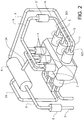
- Fig. 1 shows a vehicle in the form of a truck, or a tractor for a semitrailer. It should be noted however that the invention is applicable to a variety of alternative types of vehicles, such as a car, a bus, or a working machine such as a wheel loader.
- the vehicle comprises an internal combustion engine system 1.
- Fig. 2 is schematic and does not show, for simplicity of this presentation, certain parts such as devices for the actuation of inlet and outlet valves in cylinders of the engine system.
- the engine system 1 comprises a multi-stage compression and expansion internal combustion engine.
- the engine comprises three combustors 4, in the form of cylinders with pistons, and three piston compressors 3.
- the system further comprises an air guide 34 arranged to guide compressed air from the compressors 3 to the combustors 4.
- the air guide 34 is arranged such that the air therein passes through a heat exchanger 6, described closer below.
- the system further comprises three piston expanders 5 arranged to expand exhaust gases from the combustors 4 and to extract energy from the expanded exhaust gases.
- An exhaust guide 9 is arranged to guide exhaust gases from the combustors 4 to the expanders 5.
- the exhaust guide 9 comprises a pre-expander exhaust treatment device 91 described closer below.
- the exhaust guide 9 is further arranged to guide exhaust gases from the expanders 5 to the heat exchanger 6.
- the exhaust guide 9 is also arranged to guide exhaust gases from the heat exchanger 6 to a post-expander exhaust treatment device 8, described closer below.
- the engine system may comprise any number of combustors 4, compressors 3, and expanders 5.
- the combustors 4, compressors 3, and expanders 5 share a single heat exchanger 6, a single pre-expander exhaust treatment device 91, and a single post-expander exhaust treatment device 8.
- the number of air guides 34, heat exchangers 6, exhaust guides 9, pre-expander exhaust treatment devices 91, and post-expander exhaust treatment devices 8 may vary as well.
- each combustor 4 is arranged to reciprocate in the respective cylinder 402, whereby the pistons are all arranged to drive a crankshaft 2 of the engine.
- the combustor 4, the compressor 3, and the expander 5 are shown as all being located in the same cross-sectional plane; in a real implementation of the embodiment, the combustor 4, the compressor 3, and the expander 5 are preferably offset in relation to each other along the crankshaft 2.
- the combustors 4 are provided with respective sets of inlet and outlet valves 403, 404, arranged to be actuated in a manner which may be known per se, e.g. with cams mounted on camshafts, (not shown).
- the timing and the maximum movements of the valves 403, 404 may also be variable, as is also known per se.
- the combustors 4 are provided with respective fuel injectors 405 for injecting a fuel into the cylinders 402.
- the combustors 4 are arranged to provide a Diesel cycle to extract work from the air and fuel provided.
- the invention is equally applicable to engines in which the combustors are arranged to provide an Otto cycle, wherein the engine system may be provided with means for air mass flow control, such as variable inlet and outlet valves 303, 304 of the compressors 3, described further below, for controlling the air supply to the combustors 4.
- the means for air mass flow control may comprise one or more throttles for controlling the air supply to the combustors 4.
- the engine system may be provided with spark plugs in the combustors.
- the pistons 501 of the expanders 5 are arranged to drive the crankshaft 2 with the energy extracted from the exhaust gases from the combustors 4.
- the expanders 5 are provided with respective sets of inlet and outlet valves 503, 504, arranged to be actuated with cams mounted on camshafts, (not shown).
- the timing and the maximum movements of the valves 503, 504 may also be variable, as is known per se.
- the pistons 301 of the compressors 3 are all arranged to be driven by the crankshaft 2.
- the compressors 3 are provided with respective sets of said inlet and outlet valves 303, 304, arranged to be actuated with cams mounted on camshafts, (not shown).
- the timing and the maximum movements of the valves 303, 304 may also be variable, as is known per se.
- the pre-expander exhaust treatment device 91 is arranged to provide an exhaust treatment process to the exhaust gases from the combustors 4.
- the pre-expander exhaust treatment device 91 comprises an oxidation catalyst 11, and a particulate filter 12 located downstream of the oxidation catalyst 11.
- the pre-expander exhaust treatment device 91 presents in this example a circular cross-section.
- the post-expander exhaust treatment device 8 is in this example provided in the form of a selective catalytic reduction (SCR) catalyst.
- SCR catalyst 8 is arranged to receive exhaust gases from the expanders 5 and to provide an exhaust treatment process to the received exhaust gases, which process reduces nitrogen oxides (NOx) as is known per se.
- NOx nitrogen oxides
- post-expander exhaust treatment device 8 Alternatively, the post-expander exhaust treatment device 8 comprises an oxidation catalyst.
- the system also comprises three injectors 10 arranged to inject reductant for the SCR catalyst 8.
- Each injector 10 is arranged to inject the reductant directly into a respective of the expanders 5.
- the injectors 10 are controllable by a control unit (not shown), to control the timing, the flow and the duration of the redundant injections. Specifically, the timing and duration of the reductant injections are coordinated with the actuations of the expander inlet valves 503, in order to enable good mixing of the reductant with the exhaust gases in the expander.
- the injectors 10 are arranged to inject the reductant into the exhaust guide 9, upstream of the expanders 5 and downstream of the pre-expander exhaust treatment device 91.
- a single reductant injector may be provided, e.g. where the engine system is provided with a single expander 5 arranged to receive exhaust gases from a plurality of combustors 4.
- the single reductant injector may be thereby be arranged to inject the reductant upstream of, or into the single expander.
- the multi-stage compression and expansion internal combustion engine of the system in fig. 2 and fig. 3 provides a compression of the air by the compressors 3, and a further compression by the combustors 4.
- An expansion is provided by the combustors 4, and a further expansion is provided by the expanders 5.
- the multistage expansion provides a high utilization of the energy in the combustions of the engine.
- the exhaust gas temperature downstream of the expanders 5 will be relatively low, e.g. within the range of 50-250oC. This means that the temperature might be too low for the NOx reducing process in the SCR catalyst 8 to be efficient. Such a process may not be possible at all in temperatures below 150oC, and for the process to be fully efficient, the temperature usually have to reach 250oC.
- the heat exchanger 6 provides a solution to this problem.
- the heat exchanger 6 is arranged to receive exhaust gases produced by the combustors 4 and delivered by the expanders 5.
- the heat exchanger 6 is further arranged to receive compressed air from the compressor 3 before it reaches the combustors 4.
- the compressed air reaching the heat exchanger 6 may present a temperature of 200-450oC, preferably 260-350oC.
- the heat exchanger 6 is arranged for a heat exchange between the compressed air and the exhaust gases. Thereby, the heat exchanger 6 is arranged to transfer heat to the post-expander exhaust treatment device 8 via the exhaust gases. Thus, the temperature of the exhaust gases may be increased before reaching the post-expander exhaust treatment device 8 to improve the process therein.
- the combination of the heat exchanger 6 and the post-expander exhaust treatment device 8 is herein also referred to as an exhaust treatment unit.
- the heat exchanger 6 In addition to increasing the temperature for said exhaust treatment process, the heat exchanger 6 also forms a buffer volume for the air.
- the air buffer volume reduces or eliminates any requirements of correlation of the actuation timing of the compressor outlet valves 304 and the combustor inlet valves 403 to avoid losses with pulsating flows. Thanks to the air buffer volume, such valve actuation timing correlation requirements may be relaxed without increasing the risk of pulsating flows. Thereby simpler and cheaper valve control systems may be employed.
- the air buffer volume of the heat exchanger 6 suitably presents a cross-section which is larger than any lateral cross-section, perpendicular to a local intended air flow direction, of portions of the air guide 34 upstream and downstream of the heat exchanger 6.
- the system comprises an oil separator 14 arranged to receive exhaust gases from the expander 5, and to separate oil from the exhaust gases before the exhaust gases reach the heat exchanger 6 and the post-expander exhaust treatment device 8. Thereby, oil introduced to the exhaust gases, e.g. by the expanders 5, will be removed therefrom, avoiding or reducing detrimental effects it may have on the post-expander exhaust treatment device 8.
- the expanders 5 in fig. 3 are herein also referred to as first expanders 5.
- the system may comprise one or more second expanders 15 arranged to receive and expand exhaust gases from the post-expander exhaust treatment device 8 and to extract energy from the expanded exhaust gases.
- the second expander 15, schematically represented in fig. 3 may be mechanically connected, as indicated in fig. 3 with a broken line 153, to an additional compressor 31.
- the additional compressor 31 may be arranged to compress intake air before it reaches the piston compressor 3.
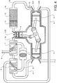
- the engine system in fig. 4 comprises a first heat exchanger 6, arranged similarly to the heat exchanger in the engine system in fig. 3 .
- the system in fig. 4 comprises a second heat exchanger 7.
- the second heat exchanger 7 is provided in the path of the air guide 34, between the first heat exchanger 6 and the combustors 4.
- the second heat exchanger 7 is arranged to receive the air from the first heat exchanger 6 before it reaches the combustors 4.
- the second heat exchanger 7 is provided in the path of the exhaust guide 9, downstream of the post-expander exhaust treatment device 8, and is thereby arranged to receive the processed exhaust gases from the exhaust treatment device 8.
- the second heat exchanger 7 is arranged to allow heat to be exchanged between the air and the exhaust gases.
- heat may be transferred in the second heat exchanger 7 from the exhaust gases to the air.
- energy in the exhaust gases can be recovered by heating the intake air after the air has delivered heat, by means of the first heat exchanger 6, to the exhaust gases for the post-expander exhaust treatment device 8.
- the system in fig. 4 also comprises three injectors 10 arranged to inject reductant for the SCR catalyst 8 into the exhaust guide 9, upstream of the expanders 5 and downstream of the pre-expander exhaust treatment device 91. More specifically, each injector 10 is arranged to inject reductant into a respective branch 901 of the exhaust guide 9; see fig. 2 . Each branch 901 is arranged to guide exhaust gases from a non-branched portion of the exhaust guide to a respective of the expanders 5.
- the injectors 10 are controllable by a control unit (not shown), to control the timing, the flow and the duration of the redundant injections. Specifically, the timing and duration of the reductant injections of each injector 10 are coordinated with the actuations of the respective expander inlet valve 503, in order to enable good mixing of the reductant with the exhaust gases in the respective expander 5.
- the (first) heat exchanger 6 is arranged to transfer the heat to the post-expander exhaust treatment device 8 via the exhaust gases.
- the heat may be transferred in a more direct manner.
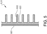
- the heat exchanger 6 and the post-expander exhaust treatment device 8 are integrated.
- the heat exchanger 6 comprises a wall 601 separating the air and the exhaust gases. It is understood that the heat exchanger preferably comprises a plurality of such walls, e.g. arranged in parallel with each other. Such a plurality of walls may define alternating cavities for the air and cavities for the exhaust gases.
- the post-expander exhaust treatment device 8 comprises an exhaust treatment layer 801 on an exhaust gas side of the wall 601, i.e. on a side of the wall facing a cavity arranged to house the exhaust gases.
- the exhaust treatment layer 801 is preferably a catalyst.
- an exhaust gas part of the heat exchanger 6 is in this example coated with a catalyst.
- the post-expander exhaust treatment device 8 may also present a portion which is arranged to receive the heat from the heat exchanger 6 via the exhaust gases, e.g. by being located downstream of the heat exchanger as in fig. 3 .
- said wall 601 of the heat exchanger 6 presents a plurality of protruding flanges 602 on an air side of the wall 601, i.e. on a side of the wall facing a cavity arranged to house the air.
- Such flanges 602 will enhance the absorption of the wall 601 of heat from the compressed air, for transfer of the heat to the exhaust treatment layer 801.
- the pistons of the compressors 3 and the expanders 5 are directly connected to the crankshaft 2 via respective connecting rods.
- the pistons of the compressors 3 and the expanders 5 may be indirectly connected to the crankshaft 2, e.g. via an additional crankshaft and a chain, belt or gear connection between the crankshafts.
Landscapes
- Engineering & Computer Science (AREA)
- Chemical & Material Sciences (AREA)
- Combustion & Propulsion (AREA)
- Mechanical Engineering (AREA)
- General Engineering & Computer Science (AREA)
- Chemical Kinetics & Catalysis (AREA)
- Health & Medical Sciences (AREA)
- Toxicology (AREA)
- Physics & Mathematics (AREA)
- Thermal Sciences (AREA)
- Exhaust Gas After Treatment (AREA)
Claims (15)
- Verbrennungsmotorsystem, umfassend- einen Verdichter (3), der angeordnet ist, um Luft zu verdichten, und- mindestens eine Brennkammer (4), wobei mindestens eine der mindestens einen Brennkammer (4) angeordnet ist, um die verdichtete Luft aufzunehmen,- wobei das System einen Wärmetauscher (6) umfasst, der angeordnet ist, um die verdichtete Luft von dem Verdichter (3) aufzunehmen, bevor sie die mindestens eine der mindestens einen Brennkammer (4) erreicht,- wobei das System eine Abgasnachbehandlungsvorrichtung (8) umfasst, die angeordnet ist, um Abgase aufzuarbeiten, die von mindestens einer der mindestens einen Brennkammer (4) erzeugt werden,- wobei das System einen Expander (5) umfasst, der angeordnet ist, um die Abgase von der mindestens einen der mindestens einen Brennkammer (4) aufzunehmen und um Energie aus den Abgasen zu expandieren und extrahieren, wobei die Abgasnachbehandlungsvorrichtung (8) angeordnet ist, um die Abgase von dem Expander (5) aufzunehmen,- dadurch gekennzeichnet, dass der Wärmetauscher angeordnet ist, um die Abgase von dem Expander aufzunehmen,- und dass der Wärmetauscher (6) angeordnet ist, um Wärme von der verdichteten Luft zur Abgasnachbehandlungsvorrichtung (8) zu transferieren, wodurch die Temperatur der Abgasnachbehandlungsvorrichtung erhöht wird, um den Vorgang darin zu verbessern.
- System nach Anspruch 1, dadurch gekennzeichnet, dass der Expander (5) einen Kolben umfasst.
- System nach einem der Ansprüche 1-2, dadurch gekennzeichnet, dass das System eine Kurbelwelle umfasst und dass der Expander (5) angeordnet ist, um die Kurbelwelle anzutreiben.
- System nach einem der Ansprüche 1-3, dadurch gekennzeichnet, dass das System einen Ölabscheider (14) umfasst, der angeordnet ist, um Abgase von dem Expander (5) aufzunehmen und um Öl von den Abgasen abzuscheiden, bevor die Abgase die Abgasnachbehandlungsvorrichtung (8) erreichen.
- System nach einem der vorhergehenden Ansprüche, dadurch gekennzeichnet, dass der Wärmetauscher (6) angeordnet ist, um die Wärme über die Abgase zu der Abgasnachbehandlungsvorrichtung (8) zu transferieren.
- System nach einem der vorhergehenden Ansprüche, dadurch gekennzeichnet, dass der Wärmetauscher (6) und die Abgasnachbehandlungsvorrichtung (8) integriert sind.
- System nach einem der vorhergehenden Ansprüche, dadurch gekennzeichnet, dass die Abgasnachbehandlungsvorrichtung (8) einen ersten Abschnitt (801) umfasst, der in den Wärmetauscher (6) integriert ist, und einen zweiten Abschnitt, der angeordnet ist, um Wärme über die von dem Wärmetauscher empfangenen Abgase aus der verdichteten Luft aufzunehmen.
- System nach einem der vorhergehenden Ansprüche, dadurch gekennzeichnet, dass die Abgasnachbehandlungsvorrichtung (8) einen Oxidationskatalysator und/oder einen SCR(Selektive katalytische Reduktion)-Katalysator umfasst.
- System nach einem der vorhergehenden Ansprüche, dadurch gekennzeichnet, dass der Wärmetauscher (6) ein erster Wärmetauscher (6) ist, wobei das System ferner einen zweiten Wärmetauscher (7) umfasst, der angeordnet ist, um die Luft von dem ersten Wärmetauscher (6) aufzunehmen, bevor sie die mindestens eine der mindestens einen Brennkammer (4) erreicht, und um die aufgearbeiteten Abgase von der Abgasnachbehandlungsvorrichtung (8) aufzunehmen, wobei der zweite Wärmetauscher (7) angeordnet ist, um zu gestatten, dass Wärme zwischen der Luft und den Abgasen ausgetauscht werden kann.
- System nach einem der vorhergehenden Ansprüche, dadurch gekennzeichnet, dass der Wärmetauscher (6) ein Puffervolumen für die Luft bildet.
- System nach einem der vorhergehenden Ansprüche, dadurch gekennzeichnet, dass das System zusätzlich zu der Abgasnachbehandlungsvorrichtung (8) eine Abgasnachbehandlungsvorrichtung mit Vor-Expander (91) umfasst, die angeordnet ist, um Abgase von der mindestens einen der mindestens einen Brennkammer (4) aufzunehmen, um den Abgasen einen Abgasnachbehandlungsvorgang bereitzustellen und um den Expander (5) aufgearbeitete Abgase zuzuführen.
- System nach Anspruch 11, dadurch gekennzeichnet, dass die Abgasnachbehandlungsvorrichtung mit Vor-Expander (91) einen Oxidationskatalysator (11) und/oder einen Partikelfilter (12) umfasst.
- System nach einem der vorhergehenden Ansprüche, dadurch gekennzeichnet, dass der Verdichter (3) einen Kolben umfasst.
- System nach einem der vorhergehenden Ansprüche, dadurch gekennzeichnet, dass das System eine Kurbelwelle umfasst und dass der Verdichter (3) angeordnet ist, um durch die Kurbelwelle angetrieben zu werden.
- Fahrzeug, das mit einem Verbrennungsmotorsystem nach einem der Ansprüche 1-14 versehen ist.
Applications Claiming Priority (1)
| Application Number | Priority Date | Filing Date | Title |
|---|---|---|---|
| PCT/EP2015/079582 WO2017101967A1 (en) | 2015-12-14 | 2015-12-14 | An internal combustion engine system and an exhaust treatment unit for such a system |
Publications (2)
| Publication Number | Publication Date |
|---|---|
| EP3390792A1 EP3390792A1 (de) | 2018-10-24 |
| EP3390792B1 true EP3390792B1 (de) | 2019-11-27 |
Family
ID=55025027
Family Applications (1)
| Application Number | Title | Priority Date | Filing Date |
|---|---|---|---|
| EP15816708.0A Active EP3390792B1 (de) | 2015-12-14 | 2015-12-14 | Brennkraftmaschinensystem und abgasbehandlungsvorrichtung |
Country Status (4)
| Country | Link |
|---|---|
| US (1) | US10774712B2 (de) |
| EP (1) | EP3390792B1 (de) |
| CN (1) | CN108368772B (de) |
| WO (1) | WO2017101967A1 (de) |
Families Citing this family (3)
| Publication number | Priority date | Publication date | Assignee | Title |
|---|---|---|---|---|
| US10704447B2 (en) * | 2015-12-14 | 2020-07-07 | Volvo Truck Corporation | Internal combustion engine system |
| WO2018054488A1 (en) * | 2016-09-23 | 2018-03-29 | Volvo Truck Corporation | A method for controlling an internal combustion engine system |
| WO2019042575A1 (en) * | 2017-09-04 | 2019-03-07 | Volvo Truck Corporation | INTERNAL COMBUSTION ENGINE ARRANGEMENT |
Citations (1)
| Publication number | Priority date | Publication date | Assignee | Title |
|---|---|---|---|---|
| US2255925A (en) * | 1937-06-29 | 1941-09-16 | Heylandt Christian Wilhel Paul | Multistage internal-combustion engine |
Family Cites Families (35)
| Publication number | Priority date | Publication date | Assignee | Title |
|---|---|---|---|---|
| GB401239A (en) * | 1932-08-19 | 1933-11-09 | Fried Krupp Germaniawerft Ag | Improvements in or relating to supercharged four stroke cycle internal combustion engines |
| US2404395A (en) * | 1942-12-14 | 1946-07-23 | Milliken Humphreys | Apparatus for converting heat energy into useful work |
| US4653269A (en) * | 1975-03-14 | 1987-03-31 | Johnson David E | Heat engine |
| US4133172A (en) * | 1977-08-03 | 1979-01-09 | General Motors Corporation | Modified Ericsson cycle engine |
| US5603215A (en) * | 1995-03-23 | 1997-02-18 | Engelhard Corporation | Method and apparatus for treatment of exhaust streams |
| JPH0932540A (ja) * | 1995-07-13 | 1997-02-04 | Hino Motors Ltd | ディーゼルエンジンの排ガス浄化装置 |
| US6092365A (en) * | 1998-02-23 | 2000-07-25 | Leidel; James A. | Heat engine |
| ATE256570T1 (de) * | 1998-06-22 | 2004-01-15 | Silentor Holding As | Wärmerückgewinnungssystem |
| US7186101B2 (en) * | 1998-07-31 | 2007-03-06 | The Texas A&M University System | Gerotor apparatus for a quasi-isothermal Brayton cycle Engine |
| KR100763642B1 (ko) * | 1998-07-31 | 2007-10-05 | 더 텍사스 에이 앤드 엠 유니버시티 시스템 | 준등온 브레이턴 사이클 기관 |
| GB0007917D0 (en) * | 2000-03-31 | 2000-05-17 | Npower | An engine |
| ITPD20020168A1 (it) | 2002-06-21 | 2003-12-22 | Giancarlo Ravagnan | Motore a combustione interna con fasi di compressione, combustione edespansione separate ed ottimizzate. |
| MY144690A (en) * | 2003-06-20 | 2011-10-31 | Scuderi Group Llc | Split-cycle four-stroke engine |
| EP1864005A1 (de) * | 2005-03-24 | 2007-12-12 | Behr GmbH & Co. KG | Abgaswärmeübertrager, insbesondere abgaskühler für eine abgasrückführung in kraftfahrzeugen |
| JP4609243B2 (ja) * | 2005-08-30 | 2011-01-12 | 株式会社デンソー | 排気ガス再循環装置 |
| US7210469B1 (en) * | 2005-10-24 | 2007-05-01 | International Engine Intellectual Property Company, Llc | Oxidation catalyst coating in a heat exchanger |
| US7210468B1 (en) * | 2005-10-24 | 2007-05-01 | International Engine Intellectual Property Company, Llc | Heat exchanger method and apparatus |
| CN101360896A (zh) * | 2006-01-13 | 2009-02-04 | 马克卡车公司 | 控制排气和进气的温度 |
| EP1881173B1 (de) * | 2006-07-19 | 2009-05-06 | Wärtsilä Schweiz AG | Multidiffusor für eine Hubkolbenbrennkraftmaschine, sowie Hubkolbenbrennkraftmaschine |
| ES2446941T3 (es) * | 2008-03-06 | 2014-03-10 | Iveco Motorenforschung Ag | Sistema de recuperación de calor de escape |
| GB0822720D0 (en) * | 2008-12-12 | 2009-01-21 | Ricardo Uk Ltd | Split cycle reciprocating piston engine |
| US8371256B2 (en) | 2009-05-27 | 2013-02-12 | GM Global Technology Operations LLC | Internal combustion engine utilizing dual compression and dual expansion processes |
| US8596063B2 (en) * | 2009-06-18 | 2013-12-03 | GM Global Technology Operations LLC | Exhaust treatment system for an internal combustion engine |
| US7953056B2 (en) * | 2009-08-26 | 2011-05-31 | Pixart Imaging Inc. | Polling method compliant to bluetooth protocol for increasing transfer efficiency and system thereof |
| WO2012021539A2 (en) * | 2010-08-09 | 2012-02-16 | Cummins Intellectual Properties, Inc. | Waste heat recovery system for recapturing energy after engine aftertreatment systems |
| SE535773C2 (sv) * | 2010-08-13 | 2012-12-11 | Scania Cv Ab | Arrangemang för att spruta in ett reduktionsmedel i en avgasledning hos en förbränningsmotor |
| FR2968714B1 (fr) * | 2010-12-08 | 2015-04-10 | IFP Energies Nouvelles | Procede et dispositif de controle de la temperature des gaz d'echappement d'un moteur a combustion interne traversant un moyen de traitement des polluants contenus dans ces gaz |
| CN102155290B (zh) * | 2011-03-20 | 2012-07-11 | 北京理工大学 | 一种用于恢复内燃机高原动力的燃机型辅助增压系统 |
| DE102011006388A1 (de) * | 2011-03-30 | 2012-10-04 | Bayerische Motoren Werke Aktiengesellschaft | Verfahren zum Betrieb einer mengengeregelten Brennkraftmaschine und Brennkraftmaschine |
| US8607566B2 (en) * | 2011-04-15 | 2013-12-17 | GM Global Technology Operations LLC | Internal combustion engine with emission treatment interposed between two expansion phases |
| US8828342B1 (en) * | 2013-10-10 | 2014-09-09 | International Engine Intellectual Property Company, Llc | DPF energy conservation |
| FI20136246A7 (fi) * | 2013-12-11 | 2015-06-12 | Waertsilae Finland Oy | Moottorin pakokaasunhallintajärjestelmä |
| FR3014947B1 (fr) * | 2013-12-13 | 2017-12-29 | Renault Sas | Ligne d'echappement de moteur a combustion interne et moteur a combustion interne comportant une telle ligne d'echappement |
| FR3033002B1 (fr) * | 2015-02-25 | 2019-05-17 | Valeo Systemes Thermiques | Dispositif de gestion thermique de l'air d'admission d'un moteur. |
| US10724450B2 (en) * | 2016-07-18 | 2020-07-28 | Aerodyn Combustion LLC | Enhanced pressure wave supercharger system and method thereof |
-
2015
- 2015-12-14 US US16/060,968 patent/US10774712B2/en active Active
- 2015-12-14 EP EP15816708.0A patent/EP3390792B1/de active Active
- 2015-12-14 CN CN201580085299.8A patent/CN108368772B/zh active Active
- 2015-12-14 WO PCT/EP2015/079582 patent/WO2017101967A1/en not_active Ceased
Patent Citations (1)
| Publication number | Priority date | Publication date | Assignee | Title |
|---|---|---|---|---|
| US2255925A (en) * | 1937-06-29 | 1941-09-16 | Heylandt Christian Wilhel Paul | Multistage internal-combustion engine |
Also Published As
| Publication number | Publication date |
|---|---|
| US20180363526A1 (en) | 2018-12-20 |
| US10774712B2 (en) | 2020-09-15 |
| EP3390792A1 (de) | 2018-10-24 |
| CN108368772B (zh) | 2020-11-06 |
| WO2017101967A1 (en) | 2017-06-22 |
| CN108368772A (zh) | 2018-08-03 |
Similar Documents
| Publication | Publication Date | Title |
|---|---|---|
| US11286847B2 (en) | Internal combustion engine system and a method for an internal combustion engine system | |
| CN104487668B (zh) | 紧凑式排气处理系统和操作该系统的方法 | |
| US20120260627A1 (en) | Internal combustion engine with emission treatment interposed between two expansion phases | |
| JP2014077446A (ja) | 内燃機関 | |
| EP3390792B1 (de) | Brennkraftmaschinensystem und abgasbehandlungsvorrichtung | |
| EP3390793B1 (de) | Verbrennungsmotorsystem | |
| SE540234C2 (en) | Multiple bank exhaust system for a turbocharged internal combustion engine comprising reductant supply system | |
| US9897026B2 (en) | In-engine heating mode by increasing load | |
| EP3516187B1 (de) | Verfahren zur steuerung eines verbrennungsmotorsystems | |
| Nagar et al. | Simulation and Analysis of After-Treatment Systems (ATS) for Opposed-Piston 2 stroke Engine | |
| WO2020001755A1 (en) | An improved method for controlling an internal combustion engine | |
| US20200232365A1 (en) | ENGINE SYSTEM AND OPERATING STRATEGY FOR SELECTIVE IN SITU AND EX SITU LIMITING OF NOx PRODUCTION | |
| WO2020046718A1 (en) | Thermal management of exhaust gas aftertreatment devices of opposed-piston engines under motoring conditions | |
| US20200232397A1 (en) | A method for controlling an internal combustion engine system | |
| US10947881B2 (en) | Reductant generator | |
| EP3379067B1 (de) | Motorsystem | |
| EP3071809B1 (de) | Anordnung zur behandlung von abgas in einem turbogeladenen verbrennungsmotor und verfahren zum betrieb einer aufgeladenen brennkraftmaschine | |
| WO2019129910A1 (es) | Equipo de recuperación de energía de gases procedentes de la combustión | |
| KR20160098609A (ko) | 터보차저 엔진 |
Legal Events
| Date | Code | Title | Description |
|---|---|---|---|
| STAA | Information on the status of an ep patent application or granted ep patent |
Free format text: STATUS: THE INTERNATIONAL PUBLICATION HAS BEEN MADE |
|
| PUAI | Public reference made under article 153(3) epc to a published international application that has entered the european phase |
Free format text: ORIGINAL CODE: 0009012 |
|
| STAA | Information on the status of an ep patent application or granted ep patent |
Free format text: STATUS: REQUEST FOR EXAMINATION WAS MADE |
|
| 17P | Request for examination filed |
Effective date: 20180615 |
|
| AK | Designated contracting states |
Kind code of ref document: A1 Designated state(s): AL AT BE BG CH CY CZ DE DK EE ES FI FR GB GR HR HU IE IS IT LI LT LU LV MC MK MT NL NO PL PT RO RS SE SI SK SM TR |
|
| AX | Request for extension of the european patent |
Extension state: BA ME |
|
| DAV | Request for validation of the european patent (deleted) | ||
| DAX | Request for extension of the european patent (deleted) | ||
| STAA | Information on the status of an ep patent application or granted ep patent |
Free format text: STATUS: EXAMINATION IS IN PROGRESS |
|
| 17Q | First examination report despatched |
Effective date: 20190404 |
|
| GRAP | Despatch of communication of intention to grant a patent |
Free format text: ORIGINAL CODE: EPIDOSNIGR1 |
|
| STAA | Information on the status of an ep patent application or granted ep patent |
Free format text: STATUS: GRANT OF PATENT IS INTENDED |
|
| INTG | Intention to grant announced |
Effective date: 20190621 |
|
| GRAS | Grant fee paid |
Free format text: ORIGINAL CODE: EPIDOSNIGR3 |
|
| GRAA | (expected) grant |
Free format text: ORIGINAL CODE: 0009210 |
|
| STAA | Information on the status of an ep patent application or granted ep patent |
Free format text: STATUS: THE PATENT HAS BEEN GRANTED |
|
| AK | Designated contracting states |
Kind code of ref document: B1 Designated state(s): AL AT BE BG CH CY CZ DE DK EE ES FI FR GB GR HR HU IE IS IT LI LT LU LV MC MK MT NL NO PL PT RO RS SE SI SK SM TR |
|
| REG | Reference to a national code |
Ref country code: GB Ref legal event code: FG4D |
|
| REG | Reference to a national code |
Ref country code: CH Ref legal event code: EP |
|
| REG | Reference to a national code |
Ref country code: DE Ref legal event code: R096 Ref document number: 602015042632 Country of ref document: DE |
|
| REG | Reference to a national code |
Ref country code: AT Ref legal event code: REF Ref document number: 1206901 Country of ref document: AT Kind code of ref document: T Effective date: 20191215 |
|
| REG | Reference to a national code |
Ref country code: IE Ref legal event code: FG4D |
|
| REG | Reference to a national code |
Ref country code: NL Ref legal event code: MP Effective date: 20191127 |
|
| REG | Reference to a national code |
Ref country code: LT Ref legal event code: MG4D |
|
| PG25 | Lapsed in a contracting state [announced via postgrant information from national office to epo] |
Ref country code: GR Free format text: LAPSE BECAUSE OF FAILURE TO SUBMIT A TRANSLATION OF THE DESCRIPTION OR TO PAY THE FEE WITHIN THE PRESCRIBED TIME-LIMIT Effective date: 20200228 Ref country code: LT Free format text: LAPSE BECAUSE OF FAILURE TO SUBMIT A TRANSLATION OF THE DESCRIPTION OR TO PAY THE FEE WITHIN THE PRESCRIBED TIME-LIMIT Effective date: 20191127 Ref country code: NL Free format text: LAPSE BECAUSE OF FAILURE TO SUBMIT A TRANSLATION OF THE DESCRIPTION OR TO PAY THE FEE WITHIN THE PRESCRIBED TIME-LIMIT Effective date: 20191127 Ref country code: SE Free format text: LAPSE BECAUSE OF FAILURE TO SUBMIT A TRANSLATION OF THE DESCRIPTION OR TO PAY THE FEE WITHIN THE PRESCRIBED TIME-LIMIT Effective date: 20191127 Ref country code: LV Free format text: LAPSE BECAUSE OF FAILURE TO SUBMIT A TRANSLATION OF THE DESCRIPTION OR TO PAY THE FEE WITHIN THE PRESCRIBED TIME-LIMIT Effective date: 20191127 Ref country code: NO Free format text: LAPSE BECAUSE OF FAILURE TO SUBMIT A TRANSLATION OF THE DESCRIPTION OR TO PAY THE FEE WITHIN THE PRESCRIBED TIME-LIMIT Effective date: 20200227 Ref country code: FI Free format text: LAPSE BECAUSE OF FAILURE TO SUBMIT A TRANSLATION OF THE DESCRIPTION OR TO PAY THE FEE WITHIN THE PRESCRIBED TIME-LIMIT Effective date: 20191127 Ref country code: BG Free format text: LAPSE BECAUSE OF FAILURE TO SUBMIT A TRANSLATION OF THE DESCRIPTION OR TO PAY THE FEE WITHIN THE PRESCRIBED TIME-LIMIT Effective date: 20200227 |
|
| PG25 | Lapsed in a contracting state [announced via postgrant information from national office to epo] |
Ref country code: RS Free format text: LAPSE BECAUSE OF FAILURE TO SUBMIT A TRANSLATION OF THE DESCRIPTION OR TO PAY THE FEE WITHIN THE PRESCRIBED TIME-LIMIT Effective date: 20191127 Ref country code: HR Free format text: LAPSE BECAUSE OF FAILURE TO SUBMIT A TRANSLATION OF THE DESCRIPTION OR TO PAY THE FEE WITHIN THE PRESCRIBED TIME-LIMIT Effective date: 20191127 Ref country code: IS Free format text: LAPSE BECAUSE OF FAILURE TO SUBMIT A TRANSLATION OF THE DESCRIPTION OR TO PAY THE FEE WITHIN THE PRESCRIBED TIME-LIMIT Effective date: 20200327 |
|
| PG25 | Lapsed in a contracting state [announced via postgrant information from national office to epo] |
Ref country code: AL Free format text: LAPSE BECAUSE OF FAILURE TO SUBMIT A TRANSLATION OF THE DESCRIPTION OR TO PAY THE FEE WITHIN THE PRESCRIBED TIME-LIMIT Effective date: 20191127 |
|
| PG25 | Lapsed in a contracting state [announced via postgrant information from national office to epo] |
Ref country code: DK Free format text: LAPSE BECAUSE OF FAILURE TO SUBMIT A TRANSLATION OF THE DESCRIPTION OR TO PAY THE FEE WITHIN THE PRESCRIBED TIME-LIMIT Effective date: 20191127 Ref country code: CZ Free format text: LAPSE BECAUSE OF FAILURE TO SUBMIT A TRANSLATION OF THE DESCRIPTION OR TO PAY THE FEE WITHIN THE PRESCRIBED TIME-LIMIT Effective date: 20191127 Ref country code: ES Free format text: LAPSE BECAUSE OF FAILURE TO SUBMIT A TRANSLATION OF THE DESCRIPTION OR TO PAY THE FEE WITHIN THE PRESCRIBED TIME-LIMIT Effective date: 20191127 Ref country code: PT Free format text: LAPSE BECAUSE OF FAILURE TO SUBMIT A TRANSLATION OF THE DESCRIPTION OR TO PAY THE FEE WITHIN THE PRESCRIBED TIME-LIMIT Effective date: 20200419 Ref country code: EE Free format text: LAPSE BECAUSE OF FAILURE TO SUBMIT A TRANSLATION OF THE DESCRIPTION OR TO PAY THE FEE WITHIN THE PRESCRIBED TIME-LIMIT Effective date: 20191127 Ref country code: RO Free format text: LAPSE BECAUSE OF FAILURE TO SUBMIT A TRANSLATION OF THE DESCRIPTION OR TO PAY THE FEE WITHIN THE PRESCRIBED TIME-LIMIT Effective date: 20191127 |
|
| REG | Reference to a national code |
Ref country code: CH Ref legal event code: PL |
|
| REG | Reference to a national code |
Ref country code: BE Ref legal event code: MM Effective date: 20191231 |
|
| REG | Reference to a national code |
Ref country code: DE Ref legal event code: R097 Ref document number: 602015042632 Country of ref document: DE |
|
| PG25 | Lapsed in a contracting state [announced via postgrant information from national office to epo] |
Ref country code: MC Free format text: LAPSE BECAUSE OF FAILURE TO SUBMIT A TRANSLATION OF THE DESCRIPTION OR TO PAY THE FEE WITHIN THE PRESCRIBED TIME-LIMIT Effective date: 20191127 Ref country code: SK Free format text: LAPSE BECAUSE OF FAILURE TO SUBMIT A TRANSLATION OF THE DESCRIPTION OR TO PAY THE FEE WITHIN THE PRESCRIBED TIME-LIMIT Effective date: 20191127 Ref country code: SM Free format text: LAPSE BECAUSE OF FAILURE TO SUBMIT A TRANSLATION OF THE DESCRIPTION OR TO PAY THE FEE WITHIN THE PRESCRIBED TIME-LIMIT Effective date: 20191127 |
|
| REG | Reference to a national code |
Ref country code: AT Ref legal event code: MK05 Ref document number: 1206901 Country of ref document: AT Kind code of ref document: T Effective date: 20191127 |
|
| PLBE | No opposition filed within time limit |
Free format text: ORIGINAL CODE: 0009261 |
|
| STAA | Information on the status of an ep patent application or granted ep patent |
Free format text: STATUS: NO OPPOSITION FILED WITHIN TIME LIMIT |
|
| GBPC | Gb: european patent ceased through non-payment of renewal fee |
Effective date: 20200227 |
|
| PG25 | Lapsed in a contracting state [announced via postgrant information from national office to epo] |
Ref country code: IE Free format text: LAPSE BECAUSE OF NON-PAYMENT OF DUE FEES Effective date: 20191214 Ref country code: LU Free format text: LAPSE BECAUSE OF NON-PAYMENT OF DUE FEES Effective date: 20191214 |
|
| 26N | No opposition filed |
Effective date: 20200828 |
|
| PG25 | Lapsed in a contracting state [announced via postgrant information from national office to epo] |
Ref country code: LI Free format text: LAPSE BECAUSE OF NON-PAYMENT OF DUE FEES Effective date: 20191231 Ref country code: SI Free format text: LAPSE BECAUSE OF FAILURE TO SUBMIT A TRANSLATION OF THE DESCRIPTION OR TO PAY THE FEE WITHIN THE PRESCRIBED TIME-LIMIT Effective date: 20191127 Ref country code: CH Free format text: LAPSE BECAUSE OF NON-PAYMENT OF DUE FEES Effective date: 20191231 Ref country code: PL Free format text: LAPSE BECAUSE OF FAILURE TO SUBMIT A TRANSLATION OF THE DESCRIPTION OR TO PAY THE FEE WITHIN THE PRESCRIBED TIME-LIMIT Effective date: 20191127 Ref country code: AT Free format text: LAPSE BECAUSE OF FAILURE TO SUBMIT A TRANSLATION OF THE DESCRIPTION OR TO PAY THE FEE WITHIN THE PRESCRIBED TIME-LIMIT Effective date: 20191127 Ref country code: BE Free format text: LAPSE BECAUSE OF NON-PAYMENT OF DUE FEES Effective date: 20191231 |
|
| PG25 | Lapsed in a contracting state [announced via postgrant information from national office to epo] |
Ref country code: GB Free format text: LAPSE BECAUSE OF NON-PAYMENT OF DUE FEES Effective date: 20200227 Ref country code: IT Free format text: LAPSE BECAUSE OF FAILURE TO SUBMIT A TRANSLATION OF THE DESCRIPTION OR TO PAY THE FEE WITHIN THE PRESCRIBED TIME-LIMIT Effective date: 20191127 |
|
| PG25 | Lapsed in a contracting state [announced via postgrant information from national office to epo] |
Ref country code: CY Free format text: LAPSE BECAUSE OF FAILURE TO SUBMIT A TRANSLATION OF THE DESCRIPTION OR TO PAY THE FEE WITHIN THE PRESCRIBED TIME-LIMIT Effective date: 20191127 |
|
| PG25 | Lapsed in a contracting state [announced via postgrant information from national office to epo] |
Ref country code: MT Free format text: LAPSE BECAUSE OF FAILURE TO SUBMIT A TRANSLATION OF THE DESCRIPTION OR TO PAY THE FEE WITHIN THE PRESCRIBED TIME-LIMIT Effective date: 20191127 Ref country code: HU Free format text: LAPSE BECAUSE OF FAILURE TO SUBMIT A TRANSLATION OF THE DESCRIPTION OR TO PAY THE FEE WITHIN THE PRESCRIBED TIME-LIMIT; INVALID AB INITIO Effective date: 20151214 |
|
| PG25 | Lapsed in a contracting state [announced via postgrant information from national office to epo] |
Ref country code: TR Free format text: LAPSE BECAUSE OF FAILURE TO SUBMIT A TRANSLATION OF THE DESCRIPTION OR TO PAY THE FEE WITHIN THE PRESCRIBED TIME-LIMIT Effective date: 20191127 |
|
| PG25 | Lapsed in a contracting state [announced via postgrant information from national office to epo] |
Ref country code: MK Free format text: LAPSE BECAUSE OF FAILURE TO SUBMIT A TRANSLATION OF THE DESCRIPTION OR TO PAY THE FEE WITHIN THE PRESCRIBED TIME-LIMIT Effective date: 20191127 |
|
| PGFP | Annual fee paid to national office [announced via postgrant information from national office to epo] |
Ref country code: FR Payment date: 20241227 Year of fee payment: 10 |
|
| PGFP | Annual fee paid to national office [announced via postgrant information from national office to epo] |
Ref country code: DE Payment date: 20241227 Year of fee payment: 10 |