EP3390779B1 - Gehäuse für drehmotor - Google Patents
Gehäuse für drehmotor Download PDFInfo
- Publication number
- EP3390779B1 EP3390779B1 EP16874184.1A EP16874184A EP3390779B1 EP 3390779 B1 EP3390779 B1 EP 3390779B1 EP 16874184 A EP16874184 A EP 16874184A EP 3390779 B1 EP3390779 B1 EP 3390779B1
- Authority
- EP
- European Patent Office
- Prior art keywords
- casing
- seal
- fluid
- engaging plate
- rotary engine
- Prior art date
- Legal status (The legal status is an assumption and is not a legal conclusion. Google has not performed a legal analysis and makes no representation as to the accuracy of the status listed.)
- Active
Links
Images
Classifications
-
- F—MECHANICAL ENGINEERING; LIGHTING; HEATING; WEAPONS; BLASTING
- F02—COMBUSTION ENGINES; HOT-GAS OR COMBUSTION-PRODUCT ENGINE PLANTS
- F02B—INTERNAL-COMBUSTION PISTON ENGINES; COMBUSTION ENGINES IN GENERAL
- F02B55/00—Internal-combustion aspects of rotary pistons; Outer members for co-operation with rotary pistons
- F02B55/08—Outer members for co-operation with rotary pistons; Casings
- F02B55/10—Cooling thereof
-
- F—MECHANICAL ENGINEERING; LIGHTING; HEATING; WEAPONS; BLASTING
- F01—MACHINES OR ENGINES IN GENERAL; ENGINE PLANTS IN GENERAL; STEAM ENGINES
- F01C—ROTARY-PISTON OR OSCILLATING-PISTON MACHINES OR ENGINES
- F01C1/00—Rotary-piston machines or engines
- F01C1/22—Rotary-piston machines or engines of internal-axis type with equidirectional movement of co-operating members at the points of engagement, or with one of the co-operating members being stationary, the inner member having more teeth or tooth- equivalents than the outer member
-
- F—MECHANICAL ENGINEERING; LIGHTING; HEATING; WEAPONS; BLASTING
- F01—MACHINES OR ENGINES IN GENERAL; ENGINE PLANTS IN GENERAL; STEAM ENGINES
- F01C—ROTARY-PISTON OR OSCILLATING-PISTON MACHINES OR ENGINES
- F01C11/00—Combinations of two or more machines or engines, each being of rotary-piston or oscillating-piston type
- F01C11/002—Combinations of two or more machines or engines, each being of rotary-piston or oscillating-piston type of similar working principle
-
- F—MECHANICAL ENGINEERING; LIGHTING; HEATING; WEAPONS; BLASTING
- F01—MACHINES OR ENGINES IN GENERAL; ENGINE PLANTS IN GENERAL; STEAM ENGINES
- F01C—ROTARY-PISTON OR OSCILLATING-PISTON MACHINES OR ENGINES
- F01C19/00—Sealing arrangements in rotary-piston machines or engines
- F01C19/12—Sealing arrangements in rotary-piston machines or engines for other than working fluid
-
- F—MECHANICAL ENGINEERING; LIGHTING; HEATING; WEAPONS; BLASTING
- F01—MACHINES OR ENGINES IN GENERAL; ENGINE PLANTS IN GENERAL; STEAM ENGINES
- F01C—ROTARY-PISTON OR OSCILLATING-PISTON MACHINES OR ENGINES
- F01C21/00—Component parts, details or accessories not provided for in groups F01C1/00 - F01C20/00
- F01C21/06—Heating; Cooling; Heat insulation
-
- F—MECHANICAL ENGINEERING; LIGHTING; HEATING; WEAPONS; BLASTING
- F01—MACHINES OR ENGINES IN GENERAL; ENGINE PLANTS IN GENERAL; STEAM ENGINES
- F01C—ROTARY-PISTON OR OSCILLATING-PISTON MACHINES OR ENGINES
- F01C21/00—Component parts, details or accessories not provided for in groups F01C1/00 - F01C20/00
- F01C21/10—Outer members for co-operation with rotary pistons; Casings
- F01C21/104—Stators; Members defining the outer boundaries of the working chamber
- F01C21/108—Stators; Members defining the outer boundaries of the working chamber with an axial surface, e.g. side plates
-
- F—MECHANICAL ENGINEERING; LIGHTING; HEATING; WEAPONS; BLASTING
- F02—COMBUSTION ENGINES; HOT-GAS OR COMBUSTION-PRODUCT ENGINE PLANTS
- F02B—INTERNAL-COMBUSTION PISTON ENGINES; COMBUSTION ENGINES IN GENERAL
- F02B53/00—Internal-combustion aspects of rotary-piston or oscillating-piston engines
- F02B53/04—Charge admission or combustion-gas discharge
-
- F—MECHANICAL ENGINEERING; LIGHTING; HEATING; WEAPONS; BLASTING
- F02—COMBUSTION ENGINES; HOT-GAS OR COMBUSTION-PRODUCT ENGINE PLANTS
- F02B—INTERNAL-COMBUSTION PISTON ENGINES; COMBUSTION ENGINES IN GENERAL
- F02B53/00—Internal-combustion aspects of rotary-piston or oscillating-piston engines
- F02B53/10—Fuel supply; Introducing fuel to combustion space
-
- F—MECHANICAL ENGINEERING; LIGHTING; HEATING; WEAPONS; BLASTING
- F02—COMBUSTION ENGINES; HOT-GAS OR COMBUSTION-PRODUCT ENGINE PLANTS
- F02B—INTERNAL-COMBUSTION PISTON ENGINES; COMBUSTION ENGINES IN GENERAL
- F02B55/00—Internal-combustion aspects of rotary pistons; Outer members for co-operation with rotary pistons
- F02B55/08—Outer members for co-operation with rotary pistons; Casings
-
- F—MECHANICAL ENGINEERING; LIGHTING; HEATING; WEAPONS; BLASTING
- F02—COMBUSTION ENGINES; HOT-GAS OR COMBUSTION-PRODUCT ENGINE PLANTS
- F02B—INTERNAL-COMBUSTION PISTON ENGINES; COMBUSTION ENGINES IN GENERAL
- F02B55/00—Internal-combustion aspects of rotary pistons; Outer members for co-operation with rotary pistons
- F02B55/14—Shapes or constructions of combustion chambers
-
- F—MECHANICAL ENGINEERING; LIGHTING; HEATING; WEAPONS; BLASTING
- F01—MACHINES OR ENGINES IN GENERAL; ENGINE PLANTS IN GENERAL; STEAM ENGINES
- F01C—ROTARY-PISTON OR OSCILLATING-PISTON MACHINES OR ENGINES
- F01C20/00—Control of, monitoring of, or safety arrangements for, machines or engines
- F01C20/02—Control of, monitoring of, or safety arrangements for, machines or engines specially adapted for several machines or engines connected in series or in parallel
-
- F—MECHANICAL ENGINEERING; LIGHTING; HEATING; WEAPONS; BLASTING
- F02—COMBUSTION ENGINES; HOT-GAS OR COMBUSTION-PRODUCT ENGINE PLANTS
- F02B—INTERNAL-COMBUSTION PISTON ENGINES; COMBUSTION ENGINES IN GENERAL
- F02B53/00—Internal-combustion aspects of rotary-piston or oscillating-piston engines
- F02B2053/005—Wankel engines
-
- Y—GENERAL TAGGING OF NEW TECHNOLOGICAL DEVELOPMENTS; GENERAL TAGGING OF CROSS-SECTIONAL TECHNOLOGIES SPANNING OVER SEVERAL SECTIONS OF THE IPC; TECHNICAL SUBJECTS COVERED BY FORMER USPC CROSS-REFERENCE ART COLLECTIONS [XRACs] AND DIGESTS
- Y02—TECHNOLOGIES OR APPLICATIONS FOR MITIGATION OR ADAPTATION AGAINST CLIMATE CHANGE
- Y02T—CLIMATE CHANGE MITIGATION TECHNOLOGIES RELATED TO TRANSPORTATION
- Y02T10/00—Road transport of goods or passengers
- Y02T10/10—Internal combustion engine [ICE] based vehicles
- Y02T10/12—Improving ICE efficiencies
Definitions
- the application relates generally to rotary engines, and more particularly, to engine casings for such engines.
- liquid cooling is provided in the side or end casings, and when multiple rotors are present, in the intermediate casing(s).
- fluid cavities are provided to cool the rotor housings.
- the manufacturing of such engine casings can be complex and limited to specific manufacturing methods, such as casting.
- the casings have surfaces in sliding contact with the rotating rotors, wear and damage is inevitable. Yet, because of the cooling passages these can be expensive components to replace.
- DE 101 24 561 A1 discloses a prior art rotary engine casing having the features of the preamble of claim 1.
- US 2002/015652 A1 , DE 10 2008 015031 A1 , US 3 151 807 A and US 3 289 647 A may also be useful for understanding the invention.
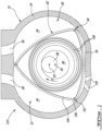
- a rotary engine 120 is shown.
- the rotary engine is a Wankel engine and comprises a casing 10 having at least one internal cavity 32 (only one being visible in Fig. 1 ), each internal cavity 32 being defined by two axially spaced apart end walls 80 interconnected by a peripheral wall 34.
- Each internal cavity 32 has a profile defining two lobes, which is preferably an epitrochoid.
- a rotor 82 is received within each internal cavity 32.
- the rotor defines three circumferentially-spaced apex portions 84, and a generally triangular profile with outwardly arched sides.
- the apex portions 84 are in sealing engagement with the inner surface of the peripheral wall 34 of the casing 10 to form three working chambers 94 between the rotor 82 and the casing 10.
- the rotor 82 is engaged to an eccentric portion 86 of a shaft 88 to perform orbital revolutions within the internal cavity 32.
- the shaft 88 performs three rotations for each orbital revolution of the rotor 82.
- the geometrical axis 90 of the rotor 82 is offset from and parallel to the axis 92 of the casing 10.
- each chamber 94 varies in volume and moves around the internal cavity 32 to undergo the four phases of intake, compression, expansion and exhaust.
- An intake port 96 is provided through the peripheral wall 34 for successively admitting compressed air into each working chamber 94.
- An exhaust port 98 is also provided through the peripheral wall 34 for successively discharging the exhaust gases from each working chamber 94.
- Passages 100 for a glow plug, spark plug or other ignition element, as well the fuel injectors are also provided through the peripheral wall 34.
- the intake port 96, the exhaust port 98 and/or the passages 100 may be provided through one of the end walls 80 of the casing 10; and/or, the ignition element and a pilot fuel injector may communicate with a pilot subchamber (not shown) defined in the rotor casing 10 and communicating with the internal cavity 32 for providing a pilot injection.
- the pilot subchamber may be for example defined in an insert (not shown) received in the peripheral wall 34.
- the fuel injectors are common rail fuel injectors, and communicate with a source of heavy fuel (e.g. diesel, kerosene (jet fuel), equivalent biofuel), and deliver the heavy fuel into the engine(s) such that the combustion chamber is stratified with a rich fuel-air mixture near the ignition source and a leaner mixture elsewhere.
- a source of heavy fuel e.g. diesel, kerosene (jet fuel), equivalent biofuel
- the working chambers 94 are sealed, for example by spring-loaded apex seals 102 extending from the rotor 82 to engage the peripheral wall 34, and spring-loaded face or gas seals 104 and end or corner seals 106 extending from the rotor 82 to engage the end walls 80.
- the rotor 82 also includes at least one spring-loaded oil seal ring 108 biased against the end wall 80 around the bearing for the rotor 82 on the shaft eccentric portion 86.
- the oil seal ring(s) may be provided in the end walls 80 to engage the rotor 82.
- each Wankel engine has a volumetric expansion ratio of from 5 to 9, and operates following the Miller cycle, with a volumetric compression ratio lower than the volumetric expansion ratio, for example by having the intake port located closer to the top dead center (TDC) than an engine where the volumetric compression and expansion ratios are equal or similar.
- TDC top dead center
- each Wankel engine may operate with similar or equal volumetric compression and expansion ratios.
- engine 120 may vary from that of the embodiment shown.
- the configuration of the engine 120 e.g. placement of ports, number and placement of seals, number of fuel injectors, etc., may vary from that of the embodiment shown.
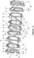
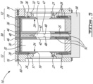
- the rotary engine casing 10 defines two axially spaced internal cavities each receiving one of two rotors engaged to a common shaft.
- the engine casing 10 includes multiple assembled casing sections which cooperate to define the internal cavities and contain the rotors and shaft, and include bearing-support features, and cooling and lubrication passages, as detailed further below.
- the engine casing 10 includes two end-casing sections 12, located at opposite ends of the engine casing 10, and each defining an end wall 80 of a respective one of the internal cavities 32, and a central-casing section 14 mounted between the two end-casing sections 12.
- the central-casing section 14 includes two rotor housings 30 each defining the peripheral wall 34 of a respective internal cavity 32, and an intermediate section 38 defining the end wall 80 extending between both internal cavities 32 to separates and seal the internal cavities 32.
- Each end-casing section 12 is split to allow separation of the end-casing section 12 into two sub-parts 16, 20 and the intermediate section 38 is split into three sub-parts 40, 46.
- the sub-parts can be machined, dowelled and/or bolted together and kept as a semi-permanent sub-assembly to ease in the process of engine assembly.
- the casing 10 is described herein with the two end-casing sections 12 and the intermediate section 38 (i.e. all end walls 80) having a split configuration, it is understood that in an alternate embodiment, only one or two of the end-casing sections 12 and intermediate section 38 may have a split configuration.
- the central-casing section 14 shown in Fig. 2 has two rotor housings 30 separated by one intermediate section 38, to receive two rotors.
- the engine 120 can have any other adequate number of rotors and accordingly the central-casing section 14 can have a corresponding number of rotor housings 30. If only one rotor housing 30 is provided, the intermediate section 38 is omitted and, if multiple rotor housings 30 are provided, each pair of rotor housings 30 is separated by an intermediate section 38.
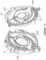
- each end-casing section 12 includes an end-casing member 16 having a mating surface 18.
- the end-casing member 16 is an end portion delimiting the axial boundary of the engine casing 10.
- Each end-casing section 12 also includes a seal-engaging plate 20 connected to the end-casing member 16.
- the seal-engaging plate 20 has a mating surface 22 abutted to the mating surface 18 of the end-casing member 16, and a sliding surface 24, which in a particular embodiment is a hardened surface, facing away from the end-casing member 16 and defining a surface of the respective internal cavity 32.
- the seal-engaging plate 20 sealingly engages the peripheral wall 34 defined by the adjacent rotor housing 30 to partially seal the corresponding internal cavity.
- the face seals 104 of the rotor 82 thus engage the sliding surfaces 24.
- the sliding surfaces 24 can have any surface finish suitable for sealing engagement with the face seals 104.
- Each end-casing member 16 has an aperture 17 defined therethrough to receive a bearing housing (not shown) supporting the engine shaft 88 ( Fig. 1 ).
- each seal-engaging plate 20 has an aperture 19 defined therethrough concentrically with the aperture of the associated end-casing member 16, sized to receive the engine shaft 88 therethrough.
- the end-casing member 16 also include oil scavenge cavities 21 defined in the mating surface 18 around the aperture, and oil circulation passages 23 in fluid communication with the scavenge cavities and with an oil reservoir 58 forming part of an oil path providing oil or other lubricating fluid circulation through the engine 120, including the central-section 14.
- each end-casing section 12 also includes at least one fluid cavity 26 in fluid communication with a source of liquid coolant (e.g. water) through a cooling fluid path of the engine casing 10, for cooling the end-casing section 12.
- the cooling fluid path includes an inlet and an outlet which may be defined in one of the end-casing sections 12, and is in fluid communication with an appropriate cooler (not shown).
- Each end-casing fluid cavity 26 is located between the mating surfaces 18, 22 and is defined by surface depression(s) 28 formed on one or both of the mating surfaces 18, 22.
- the end-casing fluid cavity 26 includes multiple cooperating surface depressions 28 formed on the mating surfaces 18, 22.
- the surface depressions 28 are sized and positioned to allow adequate cooling of the engine casing 10.
- complementary surface depressions 28 are defined in each of the mating surfaces 18, 22 and cooperate to form the end-casing fluid cavities 26.
- the end-casing fluid cavity 26 can have any configuration suitable for circulating a cooling fluid therein.
- the fluid path includes a plurality of apertures 36 defined across the engine casing 10, including the seal-engaging plate 20 and central-casing section 14, in fluid communication with the fluid cavities 26, such that the cooling fluid can circulate within the cavities 26 and through the various sections of the engine casing 10.
- the apertures 36 extend axially across seal-engaging plate 20 and central-casing section 14, from the fluid cavities 26 of one of the end-casing sections 12 to the fluid cavities 26 of the other of the end-casing sections 12. It is understood that any other adequate type of fluid communication may alternately be used.
- the surface depression(s) 28 of the end-casing fluid cavity 26 is/are located only on the mating surface 18 of the end-casing member 16. In that case, the mating surface 22 of the seal-engaging plate 20 does not include surface depressions. In another alternate embodiment which is not shown, the surface depression(s) 28 of the end-casing fluid cavity 26 is/are located on the mating surface 22 of the seal-engaging plate 20. In that case, the mating surface 18 does not include surface depressions. It is also understood that any combination of fluid cavities defined by depressions in only one of the mating surfaces 18, 22 and defined by depression in both of the mating surfaces 18, 22 can be used.
- the two end-casing sections 12 have different configurations and each end-casing sections 12 has a different number of end-casing fluid cavities 26. Alternately, the two end-casing sections 12 may have similar fluid cavities 26.
- the end-casing member 16 has a thickness greater than a thickness of the seal-engaging plate 20.
- the seal-engaging plate 20 has a thickness of 0.25 times that of the end-casing member 16; other relative dimensions may alternately be used.
- the central-casing section 14 of the particular embodiment shown includes two rotor housing 30 each defining a respective internal cavity 32 for receiving a respective rotor 82 (shown in Fig. 1 ).
- Each adjacent ones of the rotor housings 30 are separated by an intermediate section 38.
- the intermediate section 38 has similar functionalities as the end-casing section 12 described above and separates adjacent rotor housings 30 in multi-rotor engines.
- the intermediate section 38 includes an intermediate member 40 which has opposite, parallel mating surfaces 42.
- the intermediate section 38 also includes a pair of intermediate seal-engaging plates 46 connected to the intermediate member 40.
- Each intermediate seal-engaging plate 46 has a mating surface 48 abutted to a respective one of the mating surfaces 42 of the intermediate member 40 and, a sliding surface 50, which in a particular embodiment is a hardened sliding surface, facing away from the intermediate member 40 and defining a surface of the respective internal cavity 32.
- the seal-engaging plates 46 each sealingly engage the peripheral wall 34 defined by the adjacent rotor housing 30 to partially seal the corresponding internal cavity.
- the intermediate member 40 has an aperture 41 defined therethrough concentrically with the apertures 17, 19 of the end-casing sections 12 to the engine shaft 88 therethrough; although not shown, the aperture 41 could also be sized to receive a bearing housing, particularly but not exclusively for engines including more than two rotors.
- each seal-engaging plate 46 has an aperture 47 defined therethrough concentrically with the aperture of the intermediate member 40, sized to also receive the engine shaft 88 therethrough.
- the intermediate member 40 includes an oil scavenge passage 25 communicating with the aperture 41 and with the oil reservoir 58.
- the intermediate section 38 also includes at least one intermediate fluid cavity 52 in fluid communication with the fluid path of the engine casing 10, for cooling the rotor housing 30.
- Each intermediate fluid cavity 52 is located between the intermediate member 40 and the intermediate seal-engaging plates 46.
- Each intermediate fluid cavity 52 is defined by a surface depression 54 formed on the mating surface 48 of the respective seal-engaging plate 46, while the mating surfaces 42 of the intermediate member 40 are free of depressions.
- one or more of the intermediate fluid cavities 52 may be defined by depressions in the mating surface 42 of the intermediate member 40, alone or in combination with a complementary depression in the mating surface 48 of the corresponding seal-engaging plate 46. It is also understood that any combination of fluid cavities defined by depressions in only one of the abutting mating surfaces 42, 48 and defined by depression in both of the abutting mating surfaces 42, 48 can be used.
- the intermediate fluid cavity 52 can have any configuration suitable for circulating a cooling fluid therein.
- the apertures 36 of the fluid path defined across the engine casing 10 extend through the seal-engaging plates 46 and the intermediate member 40, in fluid communication with the intermediate fluid cavities 52 to connect the fluid cavities 52 to the fluid path. It is understood that any other adequate type of fluid communication may alternately be used.
- the intermediate fluid cavities 52 are shaped differently from the end-casing fluid cavities 26, and are positioned along different circumferential portions of the engine 120.
- the shape and position of the fluid cavities can be optimized based on engine operating conditions and/or configuration.
- the intermediate fluid cavities 52 are concentrated along the circumferential portion of the rotor housing 30 where combustion occurs.
- the two seal-engaging plates 46 have different configurations and different intermediate fluid cavities 52 are defined on each side of the intermediate member 40.
- the two sides of the intermediate member 40 may have similar fluid cavities 52.
- the intermediate member 40 has a thickness greater than a thickness of the seal-engaging plates 46.
- the seal-engaging plates 46 each have a thickness of 0.5 times that of the intermediate member 40; other relative dimensions may alternately be used.
- the engine casing 10 allows for replacement of the seal-engaging plates 20, 46 without replacing the entire end-casing section 12 or the entire central-casing section 14, for example in case of damage to the sliding surfaces 24, 50.
- fasteners such as circumferentially spaced bolts 60 (only one of which is shown) interconnect the sections to form the engine casing 10.
- the fluid cavities 26, 52 of the engine casing 10 are created by forming the fluid cavities on the mating surfaces of the engine casing sections.
- more economical techniques may become available, such as machining.
- manufacturing of the rotary engine casing 10 includes manufacturing a member having a first mating surface such as end-casing member 16 and/or intermediate member 40, and a seal-engaging plate having a second mating surface such as seal-engaging plate 20 and/or intermediate seal-engaging plate 46.
- the surface depression(s) can then be machined on at least one of the mating surfaces to form the fluid cavity.
- the method includes forming corresponding depressions on both mating surfaces to form the fluid cavity. Once the depressions are formed the member is assembled with the seal-engaging plate such that the surface depression defines a fluid cavity in communication with the fluid path for circulating a cooling fluid therein.
- the member and the seal-engaging plate are connected through abutment of the first and second mating surfaces.
- this includes dowelling and/or bolting the member with the seal-engaging plate in a semi-permanent sub-assembly.
- the end-casing members 16, seal-engaging plates 20, rotor housings 30, seal-engaging plates 20 and 46 intermediate member(s) 40 are made of a same material; alternately, different materials may be used.
- the split casing sections allow to ease the engine casing 10 assembly process. In such an embodiment, it is simpler and more economical to form the fluid cavities as compared to other manufacturing techniques, such as casting.
Landscapes
- Engineering & Computer Science (AREA)
- Mechanical Engineering (AREA)
- General Engineering & Computer Science (AREA)
- Chemical & Material Sciences (AREA)
- Combustion & Propulsion (AREA)
- Physics & Mathematics (AREA)
- Geometry (AREA)
- Cylinder Crankcases Of Internal Combustion Engines (AREA)
- Gasket Seals (AREA)
- Lubrication Of Internal Combustion Engines (AREA)
- Rotary Pumps (AREA)
Claims (15)
- Rotationsmotorgehäuse (10) für einen Rotationsmotor (120), der ein Lagergehäuse, eine Motorwelle (88) und einem Rotor (82) aufweist, wobei das Rotationsmotorgehäuse (10) eine erste und eine zweite axial beabstandete Endwand (80) umfasst, die durch eine Umfangswand (34) miteinander verbunden sind, wobei die erste Endwand (80), die zweite Endwand (80) und die Umfangswand (34) zusammen einen inneren Hohlraum (32) umschließen, der dazu konfiguriert ist, einen darin rotierbaren Rotor (82) dichtend in Eingriff zu nehmen, wobei mindestens die erste Endwand (80) eine geteilte Konfiguration aufweist, die eine Dichtungseingriffsplatte (20, 46) beinhaltet, welche die Umfangswand (34) dichtend in Eingriff nimmt, um den inneren Hohlraum (32) teilweise abzudichten, und ein Element (16, 40), das benachbart an der Dichtungseingriffsplatte (20, 46) außerhalb des inneren Hohlraums (32) montiert ist, wobei das Element (16, 40) eine erste Öffnung (17, 41) aufweist, die dadurch definiert ist, wobei die Dichtungseingriffsplatte (20, 46) eine zweite Öffnung (19, 47) aufweist, die konzentrisch mit der ersten Öffnung (17, 41) dadurch definiert ist, wobei die zweite Öffnung (19, 47) bemessen ist, um die Motorwelle (88) dadurch aufzunehmen, wobei die Dichtungseingriffsplatte (20, 46) eine Gleitfläche (24, 50) aufweist, die von dem Element (16, 40) abgewandt ist und eine Oberfläche des inneren Hohlraums (32) definiert, und eine Passfläche (22, 48), die an einer Passfläche (18, 42) des Elements (16, 40) anliegt, wobei sich zwischen den Passflächen (18, 42, 22, 48) des Elements (16, 40) und der Dichtungseingriffsplatte (20, 46) mindestens ein Fluidhohlraum (26, 52) befindet, wobei der mindestens eine Fluidhohlraum (26, 52) mit einer Quelle für flüssiges Kühlmittel in Verbindung steht, wobei der mindestens eine Fluidhohlraum (26, 52) dazu konfiguriert ist, den Rotor (82) in Gebrauch zu kühlen,
dadurch gekennzeichnet, dass:
die erste Öffnung (17, 41) definiert ist, um ein Lagergehäuse aufzunehmen, das die Motorwelle (88) stützt. - Rotationsmotorgehäuse nach Anspruch 1, wobei das Gehäuse (10) zwei axial beabstandete Endgehäuseabschnitte (12) beinhaltet, die sich an gegenüberliegenden Enden des Rotationsmotorgehäuse (10) befinden, und einen zentralen Gehäuseabschnitt (14), der zwischen den zwei Endgehäuseabschnitten (12) montiert und mit diesen verbunden ist, wobei der zentrale Gehäuseabschnitt (14) die Umfangswand (34) beinhaltet und sich die erste Endwand (80) in einem der Endgehäuseabschnitte (12) befindet.
- Rotationsmotorgehäuse nach Anspruch 2, wobei der zentrale Gehäuseabschnitt (14) mindestens einen zusätzlichen Fluidhohlraum (52) beinhaltet, der in Fluidverbindung mit dem mindestens einen Fluidhohlraum (26) steht, der zwischen den Passflächen (18, 22) definiert ist.
- Rotationsmotorgehäuse nach Anspruch 2 oder 3, wobei der zentrale Gehäuseabschnitt (14) eine Vielzahl von Öffnungen (36) aufweist, die sich dadurch erstrecken und mit dem mindestens einen Fluidhohlraum (26) in Verbindung stehen.
- Rotationsmotorgehäuse nach einem der vorhergehenden Ansprüche, wobei das Element (16, 40) eine Dicke aufweist, die größer als die Dicke der Dichtungseingriffsplatte (20, 46) ist.
- Rotationsmotorgehäuse nach einem der vorhergehenden Ansprüche, wobei:die Passflächen (18, 42, 22, 48) komplementäre Vertiefungen (28, 54) beinhalten, die zusammenwirken, um den mindestens einen Fluidhohlraum (26, 52) auszubilden; odereine der Passflächen (18, 42, 22, 48) mindestens eine Vertiefung (28, 54) beinhaltet, die mit der anderen der Passflächen (18, 42, 22, 48) zusammenwirkt, um den mindestens einen Fluidhohlraum (26) auszubilden.
- Rotationsmotorgehäuse nach Anspruch 1, wobei der innere Hohlraum (32) ein erster innerer Hohlraum (32) ist, die Umfangswand (34) eine erste Umfangswand (34) ist und die Dichtungseingriffsplatte (20, 46) eine erste Dichtungseingriffsplatte (46) ist, wobei das Gehäuse (10) ferner eine dritte Endwand (80) und eine zweite Umfangswand (34) umfasst, wobei die erste Endwand (80), die dritte Endwand (80) und die zweite Umfangswand (34) zusammen einen zweiten inneren Hohlraum (32) umschließen, der dazu konfiguriert ist, einen darin drehbaren zusätzlichen Rotor (82) abdichtend in Eingriff zu nehmen, wobei der erste und der zweite innere Hohlraum (32) durch die erste Endwand (80) getrennt sind, wobei die erste Endwand (80) eine zweite Dichtungseingriffsplatte (46) beinhaltet, welche die zweite Umfangswand (34) dichtend in Eingriff nimmt, um den zweiten inneren Hohlraum (32) teilweise abzudichten, wobei sich das Element (40) zwischen der ersten und der zweiten Dichtungseingriffsplatte (46) befindet, wobei das Element (40) und eine zweite Dichtungsplatte (46) anliegende Passflächen (42, 48) aufweisen, die zusammenwirken, um zwischen sich mindestens einem zusätzlichen Fluidhohlraum (52) zu definieren, der mit der Quelle des flüssigen Kühlmittels in Verbindung steht.
- Rotationsmotorgehäuse nach Anspruch 7, wobei jeder des mindestens einen Fluidhohlraums (52) durch eine entsprechende Vertiefung (54) definiert ist, die in der Passfläche (48) der ersten Dichtungseingriffsplatte (46) ausgebildet ist, und jeder des mindestens einen zusätzlichen Fluidhohlraums (52) durch eine entsprechende Vertiefung (54) definiert ist, die in der Passfläche (48) der zweiten Dichtungseingriffsplatte (46) ausgebildet ist.
- Rotationsmotorgehäuse (10) nach Anspruch 7 oder 8, wobei:die zweite und die dritte Endwand (80) jeweilige Endgehäuseabschnitte (12) definieren, die sich an gegenüberliegenden Enden des Rotationsmotorgehäuses (10) befinden;die erste und die zweite Umfangswand (34) ein jeweils erstes und zweites Rotorgehäuse (30) definieren;die erste und die zweite Dichtungseingriffsplatte (46) und das Element (40) einen Zwischenabschnitt (38) definieren, der zwischen den Rotorgehäusen (30) montiert ist; unddie Rotorgehäuse (30) und der Zwischenabschnitt (38) einen zentralen Gehäuseabschnitt (14) definieren, der zwischen den beiden Endgehäuseabschnitten (12) montiert ist.
- Rotationsmotorgehäuse nach Anspruch 9, wobei jeder Endgehäuseabschnitt (12) mindestens einen Endgehäuse-Fluidhohlraum (26) in Fluidverbindung mit dem mindestens einen Fluidhohlraum (52) und mit dem mindestens einen zusätzlichen Fluidhohlraum (52) beinhaltet.
- Rotationsmotorgehäuse nach Anspruch 9, wobei die jeweilige Endwand (80) jedes Endgehäuseabschnitts (12) eine Endgehäuse-Dichtungseingriffsplatte (20) beinhaltet, welche die Umfangswand (34) eines jeweiligen der Rotorgehäuse (30) dichtend in Eingriff nimmt, um den inneren Hohlraum (32) davon teilweise abzudichten, und ein Endgehäuseelement (16), das benachbart an der Endgehäuse-Dichtungseingriffsplatte (20) außerhalb des inneren Hohlraums (32) montiert ist, wobei das Endgehäuseelement (16) und die Endgehäuse-Dichtungseingriffsplatte (20) anliegende Passflächen (18, 22) aufweisen, die zusammenwirken, um zwischen sich mindestens einen Endgehäuse-Fluidhohlraum (26) zu definieren, der mit der Quelle des flüssigen Kühlmittels in Verbindung steht.
- Rotationsmotorgehäuse nach einem der Ansprüche 7 bis 11, wobei das Element (40) eine Dicke aufweist, die größere als die Dicke der ersten und der zweiten Dichtungseingriffsplatte (46) ist.
- Verfahren zur Herstellung eines Rotationsmotorgehäuses (10), wobei das Verfahren Folgendes umfasst:Herstellen von zwei Endgehäuseabschnitten (12), die einen ersten Teil eines Fluidpfads zum Zirkulieren eines Kühlfluids beinhalten;Herstellen eines zentralen Gehäuseabschnitts (14), der mindestens einen inneren Hohlraum (32) zur Aufnahme eines Rotors (82) und eines zweiten Teils des Fluidpfads definiert;wobei mindestens eines von dem Herstellen der zwei Endgehäuseabschnitte (12) und dem Herstellen des zentralen Gehäuseabschnitts (14) Folgendes beinhaltet:Herstellen eines Elements (16, 40), das eine erste Passfläche (18, 42) und eine erste Öffnung (17,41) aufweist, die dadurch definiert ist,Herstellen einer Dichtungseingriffsplatte (20, 46), die eine zweite Passfläche (22, 48) und eine zweite Öffnung (19, 47) aufweist, die dadurch definiert und bemessen ist, um eine Motorwelle (88) aufzunehmen, undBearbeiten von mindestens einer Oberflächenvertiefung (28, 54) auf mindestens einer der ersten und der zweiten Passfläche (18, 42, 22, 48), wobei die mindestens eine Oberflächenvertiefung (28, 54) in Fluidverbindung mit dem Fluidpfad steht; undZusammenbauen des zentralen Gehäuseabschnitts (14) zwischen den zwei Endgehäuseabschnitten (12), beinhaltend Verbinden des ersten und des zweiten Teils des Fluidpfads und Zusammenbauen des Elements (16, 40) mit der Dichtungseingriffsplatte (20, 46) außerhalb des mindestens einen inneren Hohlraums (32) durch Anlegen der ersten und der zweiten Passfläche (18, 42, 22, 48) derart, dass die erste Öffnung (17, 41) konzentrisch mit der zweiten Öffnung (19, 41) ist und die mindestens eine Oberflächenvertiefung (28, 54) einen Fluidhohlraum (26, 52) zwischen der ersten und der zweiten Passfläche (18, 42, 22, 48) definiert, wobei der Fluidhohlraum (26, 52) mit dem Fluidpfad in Verbindung steht, um ein Kühlfluid darin zirkulieren zu lassen,dadurch gekennzeichnet, dass:
die erste Öffnung (17,41) definiert ist, um ein Lagergehäuse aufzunehmen, das eine Motorwelle (88) stützt. - Verfahren nach Anspruch 13, wobei das Bearbeiten der mindestens einen Oberflächenvertiefung (28, 54) auf mindestens einer der ersten und der zweiten Passfläche (18, 42, 22, 48) ein Bearbeiten komplementärer Vertiefungen (28, 54) auf der ersten und der zweiten Passflächen (18, 42, 22, 48) beinhaltet.
- Verfahren nach Anspruch 13 oder 14, wobei:Herstellen der zwei Endgehäuseabschnitte (12) und das Herstellen des zentralen Gehäuseabschnitts (14) beide Herstellen des Elements (16, 40), Herstellen der Dichtungseingriffsplatte (20, 46) und Bearbeiten der mindestens einen Oberflächenvertiefung (28, 54) beinhalten; und/oderdas Element (16, 40) mit einer Dicke hergestellt ist, die größer als jene der Dichtungsplatte (20, 46) ist.
Applications Claiming Priority (2)
| Application Number | Priority Date | Filing Date | Title |
|---|---|---|---|
| US14/974,489 US10072566B2 (en) | 2015-12-18 | 2015-12-18 | Rotary engine casing with seal engaging plate having mating surface defining a fluid cavity |
| PCT/CA2016/050935 WO2017100906A1 (en) | 2015-12-18 | 2016-08-10 | Rotary engine casing |
Publications (3)
| Publication Number | Publication Date |
|---|---|
| EP3390779A1 EP3390779A1 (de) | 2018-10-24 |
| EP3390779A4 EP3390779A4 (de) | 2018-12-19 |
| EP3390779B1 true EP3390779B1 (de) | 2024-10-23 |
Family
ID=59055489
Family Applications (1)
| Application Number | Title | Priority Date | Filing Date |
|---|---|---|---|
| EP16874184.1A Active EP3390779B1 (de) | 2015-12-18 | 2016-08-10 | Gehäuse für drehmotor |
Country Status (4)
| Country | Link |
|---|---|
| US (3) | US10072566B2 (de) |
| EP (1) | EP3390779B1 (de) |
| CA (1) | CA2938284C (de) |
| WO (1) | WO2017100906A1 (de) |
Families Citing this family (9)
| Publication number | Priority date | Publication date | Assignee | Title |
|---|---|---|---|---|
| US10072566B2 (en) * | 2015-12-18 | 2018-09-11 | Pratt & Whitney Canada Corp. | Rotary engine casing with seal engaging plate having mating surface defining a fluid cavity |
| KR102278847B1 (ko) * | 2020-03-27 | 2021-07-19 | 엘지전자 주식회사 | 로터리 엔진 |
| KR102278846B1 (ko) * | 2020-03-27 | 2021-07-19 | 엘지전자 주식회사 | 로터리 엔진 |
| US11761376B1 (en) * | 2022-11-11 | 2023-09-19 | Pratt & Whitney Canada Corp. | Side plate for rotary engine |
| US12252991B2 (en) * | 2023-07-13 | 2025-03-18 | Pratt & Whitney Canada Corp. | Seal assembly for a rotary engine housing |
| US12152490B1 (en) | 2023-07-18 | 2024-11-26 | Pratt & Whitney Canada Corp. | Fretting resistant rotary engine housings |
| US12110819B1 (en) | 2023-09-20 | 2024-10-08 | Pratt & Whitney Canada Corp. | Side plate for rotary engine |
| US12168933B1 (en) | 2023-11-17 | 2024-12-17 | Pratt & Whitney Canada Corp. | Impingement cooling assembly for an aircraft rotary engine housing |
| US20250187126A1 (en) * | 2023-12-12 | 2025-06-12 | Pratt & Whitney Canada Corp. | Tool for assembly and storage of rotary engine |
Family Cites Families (21)
| Publication number | Priority date | Publication date | Assignee | Title |
|---|---|---|---|---|
| GB926801A (de) | 1958-10-07 | 1963-05-22 | Nsu Motorenwerke | |
| US3151807A (en) * | 1960-06-30 | 1964-10-06 | Nsu Motorenwerke Ag | Housing for rotary mechanisms |
| US3289647A (en) | 1964-08-24 | 1966-12-06 | Curtiss Wright Corp | Cooling system for multi-unit rotary mechanisms |
| IT1008088B (it) | 1972-12-21 | 1976-11-10 | Audi Ag | Carcassa per motore a combustione a pistone rotante del tipo costrut tivo trocoidale e procedimento per la sua realizzazione |
| US3791235A (en) | 1973-04-19 | 1974-02-12 | Curtiss Wright Corp | Split intermediate housing section for multi-rotor rotary mechanism |
| US3849035A (en) | 1973-05-11 | 1974-11-19 | Curtiss Wright Corp | Intermediate housing section for a multi-rotor rotary internal combustion engine and method of manufacture thereof |
| US3947160A (en) | 1974-11-21 | 1976-03-30 | Ingersoll-Rand Company | Housing and shaft arrangement |
| US3941526A (en) | 1975-02-26 | 1976-03-02 | General Motors Corporation | Rotary engine assembly |
| JPS626311Y2 (de) | 1978-10-26 | 1987-02-13 | ||
| JPS6296736A (ja) | 1985-10-23 | 1987-05-06 | Mazda Motor Corp | ロ−タリピストンエンジンのハウジング構造 |
| USRE34876E (en) | 1987-09-17 | 1995-03-14 | Adiwinata; Sofyan | Rotary internal combustion engine |
| CA2067355A1 (en) | 1989-10-04 | 1991-04-05 | Helmuth R. Uebel | Rotary piston machine |
| CN1022772C (zh) | 1992-05-16 | 1993-11-17 | 丑毅 | 组合式叶片旋转发动机 |
| JPH09158868A (ja) | 1995-12-08 | 1997-06-17 | Zexel Corp | ベーン型圧縮機 |
| DE10124561A1 (de) * | 2000-05-27 | 2001-11-29 | Brandenburgische Forschungs Un | Kreiskolbenmotor in Trochoidenbauart |
| DE10124560B4 (de) * | 2000-05-27 | 2017-01-05 | Brandenburgische Forschungs- Und Entwicklungsgesellschaft Cottbus Mbh | Kreiskolbenmotor |
| MXPA04006314A (es) | 2002-01-09 | 2004-10-04 | Karnes Dyno Rev Engine Inc | Motor de combustion interna. |
| DE102008015031B4 (de) * | 2008-03-17 | 2014-10-23 | Wankel Super Tec Gmbh | Gehäuse für einen Kreiskolbenmotor und Kreiskolbenmotor |
| US9435204B2 (en) | 2011-03-21 | 2016-09-06 | United Technologies Corporation | Structurally efficient cooled engine housing for rotary engines |
| US10072566B2 (en) * | 2015-12-18 | 2018-09-11 | Pratt & Whitney Canada Corp. | Rotary engine casing with seal engaging plate having mating surface defining a fluid cavity |
| AU2017101231C4 (en) | 2016-08-22 | 2019-06-13 | Billet Inco Pty Ltd | A Rotary Engine with Wear Plate |
-
2015
- 2015-12-18 US US14/974,489 patent/US10072566B2/en active Active
-
2016
- 2016-08-05 CA CA2938284A patent/CA2938284C/en active Active
- 2016-08-10 WO PCT/CA2016/050935 patent/WO2017100906A1/en not_active Ceased
- 2016-08-10 EP EP16874184.1A patent/EP3390779B1/de active Active
-
2018
- 2018-08-10 US US16/100,666 patent/US10473026B2/en active Active
-
2019
- 2019-10-09 US US16/597,219 patent/US10995660B2/en active Active
Also Published As
| Publication number | Publication date |
|---|---|
| US20180347457A1 (en) | 2018-12-06 |
| WO2017100906A1 (en) | 2017-06-22 |
| CA2938284C (en) | 2024-01-02 |
| US10473026B2 (en) | 2019-11-12 |
| US20170175620A1 (en) | 2017-06-22 |
| CA2938284A1 (en) | 2017-06-18 |
| US10995660B2 (en) | 2021-05-04 |
| US20200040813A1 (en) | 2020-02-06 |
| US10072566B2 (en) | 2018-09-11 |
| EP3390779A1 (de) | 2018-10-24 |
| EP3390779A4 (de) | 2018-12-19 |
Similar Documents
| Publication | Publication Date | Title |
|---|---|---|
| US10995660B2 (en) | Method of manufacturing a rotary engine casing | |
| CA2805184C (en) | Rotary internal combustion engine with cooled insert | |
| EP2775117B1 (de) | Drehverbrennungsmotor mit Pilotenunterkammer | |
| EP3772566B1 (de) | Stator für drehverbrennungsmotor mit pilotenunterkammer | |
| EP3299607B1 (de) | Verfahren zum betrieb eines motors mit einer pilotenunterkammer unter teillastbedingungen | |
| CA2782745C (en) | Apex seal arrangement for rotary internal combustion engine | |
| US20190162108A1 (en) | Rotary engine with pilot subchambers | |
| EP3361046B1 (de) | Rotierender verbrennungsmotor mit ungleichen volumenverhältnissen | |
| WO2000012867A1 (en) | Internal combustion engine | |
| RU2078957C1 (ru) | Двигатель внутреннего сгорания роторный | |
| US8905736B2 (en) | Port for rotary internal combustion engine | |
| WO2015069209A1 (en) | Rotor-piston internal combustion engine | |
| US20180274513A1 (en) | Internal combustion engine with igniter cooling sleeve |
Legal Events
| Date | Code | Title | Description |
|---|---|---|---|
| STAA | Information on the status of an ep patent application or granted ep patent |
Free format text: STATUS: THE INTERNATIONAL PUBLICATION HAS BEEN MADE |
|
| PUAI | Public reference made under article 153(3) epc to a published international application that has entered the european phase |
Free format text: ORIGINAL CODE: 0009012 |
|
| STAA | Information on the status of an ep patent application or granted ep patent |
Free format text: STATUS: REQUEST FOR EXAMINATION WAS MADE |
|
| 17P | Request for examination filed |
Effective date: 20180718 |
|
| AK | Designated contracting states |
Kind code of ref document: A1 Designated state(s): AL AT BE BG CH CY CZ DE DK EE ES FI FR GB GR HR HU IE IS IT LI LT LU LV MC MK MT NL NO PL PT RO RS SE SI SK SM TR |
|
| AX | Request for extension of the european patent |
Extension state: BA ME |
|
| A4 | Supplementary search report drawn up and despatched |
Effective date: 20181115 |
|
| RIC1 | Information provided on ipc code assigned before grant |
Ipc: F01C 1/22 20060101ALI20181109BHEP Ipc: F01C 21/10 20060101AFI20181109BHEP Ipc: F01C 19/00 20060101ALI20181109BHEP Ipc: F01C 21/06 20060101ALI20181109BHEP Ipc: F01C 11/00 20060101ALI20181109BHEP |
|
| DAV | Request for validation of the european patent (deleted) | ||
| DAX | Request for extension of the european patent (deleted) | ||
| STAA | Information on the status of an ep patent application or granted ep patent |
Free format text: STATUS: EXAMINATION IS IN PROGRESS |
|
| 17Q | First examination report despatched |
Effective date: 20220113 |
|
| REG | Reference to a national code |
Ref legal event code: R079 Ipc: F01C0019120000 Ref country code: DE Ref legal event code: R079 Ref document number: 602016089979 Country of ref document: DE Free format text: PREVIOUS MAIN CLASS: F01C0021100000 Ipc: F01C0019120000 |
|
| GRAP | Despatch of communication of intention to grant a patent |
Free format text: ORIGINAL CODE: EPIDOSNIGR1 |
|
| STAA | Information on the status of an ep patent application or granted ep patent |
Free format text: STATUS: GRANT OF PATENT IS INTENDED |
|
| RIC1 | Information provided on ipc code assigned before grant |
Ipc: F01C 11/00 20060101ALI20231117BHEP Ipc: F01C 21/06 20060101ALI20231117BHEP Ipc: F01C 21/10 20060101ALI20231117BHEP Ipc: F01C 1/22 20060101ALI20231117BHEP Ipc: F01C 20/02 20060101ALI20231117BHEP Ipc: F01C 19/12 20060101AFI20231117BHEP |
|
| INTG | Intention to grant announced |
Effective date: 20231219 |
|
| GRAJ | Information related to disapproval of communication of intention to grant by the applicant or resumption of examination proceedings by the epo deleted |
Free format text: ORIGINAL CODE: EPIDOSDIGR1 |
|
| STAA | Information on the status of an ep patent application or granted ep patent |
Free format text: STATUS: EXAMINATION IS IN PROGRESS |
|
| GRAP | Despatch of communication of intention to grant a patent |
Free format text: ORIGINAL CODE: EPIDOSNIGR1 |
|
| STAA | Information on the status of an ep patent application or granted ep patent |
Free format text: STATUS: GRANT OF PATENT IS INTENDED |
|
| INTC | Intention to grant announced (deleted) | ||
| INTG | Intention to grant announced |
Effective date: 20240513 |
|
| GRAS | Grant fee paid |
Free format text: ORIGINAL CODE: EPIDOSNIGR3 |
|
| GRAA | (expected) grant |
Free format text: ORIGINAL CODE: 0009210 |
|
| STAA | Information on the status of an ep patent application or granted ep patent |
Free format text: STATUS: THE PATENT HAS BEEN GRANTED |
|
| AK | Designated contracting states |
Kind code of ref document: B1 Designated state(s): AL AT BE BG CH CY CZ DE DK EE ES FI FR GB GR HR HU IE IS IT LI LT LU LV MC MK MT NL NO PL PT RO RS SE SI SK SM TR |
|
| REG | Reference to a national code |
Ref country code: GB Ref legal event code: FG4D |
|
| REG | Reference to a national code |
Ref country code: CH Ref legal event code: EP |
|
| REG | Reference to a national code |
Ref country code: DE Ref legal event code: R096 Ref document number: 602016089979 Country of ref document: DE |
|
| REG | Reference to a national code |
Ref country code: IE Ref legal event code: FG4D |
|
| REG | Reference to a national code |
Ref country code: LT Ref legal event code: MG9D |
|
| REG | Reference to a national code |
Ref country code: NL Ref legal event code: MP Effective date: 20241023 |
|
| REG | Reference to a national code |
Ref country code: AT Ref legal event code: MK05 Ref document number: 1734988 Country of ref document: AT Kind code of ref document: T Effective date: 20241023 |
|
| PG25 | Lapsed in a contracting state [announced via postgrant information from national office to epo] |
Ref country code: NL Free format text: LAPSE BECAUSE OF FAILURE TO SUBMIT A TRANSLATION OF THE DESCRIPTION OR TO PAY THE FEE WITHIN THE PRESCRIBED TIME-LIMIT Effective date: 20241023 |
|
| PG25 | Lapsed in a contracting state [announced via postgrant information from national office to epo] |
Ref country code: NL Free format text: LAPSE BECAUSE OF FAILURE TO SUBMIT A TRANSLATION OF THE DESCRIPTION OR TO PAY THE FEE WITHIN THE PRESCRIBED TIME-LIMIT Effective date: 20241023 |
|
| PG25 | Lapsed in a contracting state [announced via postgrant information from national office to epo] |
Ref country code: IS Free format text: LAPSE BECAUSE OF FAILURE TO SUBMIT A TRANSLATION OF THE DESCRIPTION OR TO PAY THE FEE WITHIN THE PRESCRIBED TIME-LIMIT Effective date: 20250223 Ref country code: HR Free format text: LAPSE BECAUSE OF FAILURE TO SUBMIT A TRANSLATION OF THE DESCRIPTION OR TO PAY THE FEE WITHIN THE PRESCRIBED TIME-LIMIT Effective date: 20241023 Ref country code: PT Free format text: LAPSE BECAUSE OF FAILURE TO SUBMIT A TRANSLATION OF THE DESCRIPTION OR TO PAY THE FEE WITHIN THE PRESCRIBED TIME-LIMIT Effective date: 20250224 |
|
| PG25 | Lapsed in a contracting state [announced via postgrant information from national office to epo] |
Ref country code: FI Free format text: LAPSE BECAUSE OF FAILURE TO SUBMIT A TRANSLATION OF THE DESCRIPTION OR TO PAY THE FEE WITHIN THE PRESCRIBED TIME-LIMIT Effective date: 20241023 |
|
| PG25 | Lapsed in a contracting state [announced via postgrant information from national office to epo] |
Ref country code: BG Free format text: LAPSE BECAUSE OF FAILURE TO SUBMIT A TRANSLATION OF THE DESCRIPTION OR TO PAY THE FEE WITHIN THE PRESCRIBED TIME-LIMIT Effective date: 20241023 |
|
| PG25 | Lapsed in a contracting state [announced via postgrant information from national office to epo] |
Ref country code: ES Free format text: LAPSE BECAUSE OF FAILURE TO SUBMIT A TRANSLATION OF THE DESCRIPTION OR TO PAY THE FEE WITHIN THE PRESCRIBED TIME-LIMIT Effective date: 20241023 |
|
| PG25 | Lapsed in a contracting state [announced via postgrant information from national office to epo] |
Ref country code: NO Free format text: LAPSE BECAUSE OF FAILURE TO SUBMIT A TRANSLATION OF THE DESCRIPTION OR TO PAY THE FEE WITHIN THE PRESCRIBED TIME-LIMIT Effective date: 20250123 |
|
| PG25 | Lapsed in a contracting state [announced via postgrant information from national office to epo] |
Ref country code: LV Free format text: LAPSE BECAUSE OF FAILURE TO SUBMIT A TRANSLATION OF THE DESCRIPTION OR TO PAY THE FEE WITHIN THE PRESCRIBED TIME-LIMIT Effective date: 20241023 Ref country code: GR Free format text: LAPSE BECAUSE OF FAILURE TO SUBMIT A TRANSLATION OF THE DESCRIPTION OR TO PAY THE FEE WITHIN THE PRESCRIBED TIME-LIMIT Effective date: 20250124 Ref country code: AT Free format text: LAPSE BECAUSE OF FAILURE TO SUBMIT A TRANSLATION OF THE DESCRIPTION OR TO PAY THE FEE WITHIN THE PRESCRIBED TIME-LIMIT Effective date: 20241023 |
|
| PG25 | Lapsed in a contracting state [announced via postgrant information from national office to epo] |
Ref country code: PL Free format text: LAPSE BECAUSE OF FAILURE TO SUBMIT A TRANSLATION OF THE DESCRIPTION OR TO PAY THE FEE WITHIN THE PRESCRIBED TIME-LIMIT Effective date: 20241023 |
|
| PG25 | Lapsed in a contracting state [announced via postgrant information from national office to epo] |
Ref country code: RS Free format text: LAPSE BECAUSE OF FAILURE TO SUBMIT A TRANSLATION OF THE DESCRIPTION OR TO PAY THE FEE WITHIN THE PRESCRIBED TIME-LIMIT Effective date: 20250123 |
|
| PG25 | Lapsed in a contracting state [announced via postgrant information from national office to epo] |
Ref country code: SM Free format text: LAPSE BECAUSE OF FAILURE TO SUBMIT A TRANSLATION OF THE DESCRIPTION OR TO PAY THE FEE WITHIN THE PRESCRIBED TIME-LIMIT Effective date: 20241023 |
|
| PG25 | Lapsed in a contracting state [announced via postgrant information from national office to epo] |
Ref country code: DK Free format text: LAPSE BECAUSE OF FAILURE TO SUBMIT A TRANSLATION OF THE DESCRIPTION OR TO PAY THE FEE WITHIN THE PRESCRIBED TIME-LIMIT Effective date: 20241023 |
|
| PG25 | Lapsed in a contracting state [announced via postgrant information from national office to epo] |
Ref country code: EE Free format text: LAPSE BECAUSE OF FAILURE TO SUBMIT A TRANSLATION OF THE DESCRIPTION OR TO PAY THE FEE WITHIN THE PRESCRIBED TIME-LIMIT Effective date: 20241023 |
|
| PG25 | Lapsed in a contracting state [announced via postgrant information from national office to epo] |
Ref country code: RO Free format text: LAPSE BECAUSE OF FAILURE TO SUBMIT A TRANSLATION OF THE DESCRIPTION OR TO PAY THE FEE WITHIN THE PRESCRIBED TIME-LIMIT Effective date: 20241023 |
|
| REG | Reference to a national code |
Ref country code: DE Ref legal event code: R097 Ref document number: 602016089979 Country of ref document: DE |
|
| PG25 | Lapsed in a contracting state [announced via postgrant information from national office to epo] |
Ref country code: SK Free format text: LAPSE BECAUSE OF FAILURE TO SUBMIT A TRANSLATION OF THE DESCRIPTION OR TO PAY THE FEE WITHIN THE PRESCRIBED TIME-LIMIT Effective date: 20241023 |
|
| PG25 | Lapsed in a contracting state [announced via postgrant information from national office to epo] |
Ref country code: CZ Free format text: LAPSE BECAUSE OF FAILURE TO SUBMIT A TRANSLATION OF THE DESCRIPTION OR TO PAY THE FEE WITHIN THE PRESCRIBED TIME-LIMIT Effective date: 20241023 |
|
| PG25 | Lapsed in a contracting state [announced via postgrant information from national office to epo] |
Ref country code: IT Free format text: LAPSE BECAUSE OF FAILURE TO SUBMIT A TRANSLATION OF THE DESCRIPTION OR TO PAY THE FEE WITHIN THE PRESCRIBED TIME-LIMIT Effective date: 20241023 |
|
| PLBE | No opposition filed within time limit |
Free format text: ORIGINAL CODE: 0009261 |
|
| STAA | Information on the status of an ep patent application or granted ep patent |
Free format text: STATUS: NO OPPOSITION FILED WITHIN TIME LIMIT |
|
| PG25 | Lapsed in a contracting state [announced via postgrant information from national office to epo] |
Ref country code: SE Free format text: LAPSE BECAUSE OF FAILURE TO SUBMIT A TRANSLATION OF THE DESCRIPTION OR TO PAY THE FEE WITHIN THE PRESCRIBED TIME-LIMIT Effective date: 20241023 |
|
| 26N | No opposition filed |
Effective date: 20250724 |
|
| PGFP | Annual fee paid to national office [announced via postgrant information from national office to epo] |
Ref country code: DE Payment date: 20250724 Year of fee payment: 10 |
|
| PGFP | Annual fee paid to national office [announced via postgrant information from national office to epo] |
Ref country code: GB Payment date: 20250725 Year of fee payment: 10 |
|
| PGFP | Annual fee paid to national office [announced via postgrant information from national office to epo] |
Ref country code: FR Payment date: 20250725 Year of fee payment: 10 |
|
| REG | Reference to a national code |
Ref country code: CH Ref legal event code: H13 Free format text: ST27 STATUS EVENT CODE: U-0-0-H10-H13 (AS PROVIDED BY THE NATIONAL OFFICE) Effective date: 20260324 |