EP3390069B1 - Verfahren zur herstellung eines sicherheitselements sowie transferfolie - Google Patents
Verfahren zur herstellung eines sicherheitselements sowie transferfolie Download PDFInfo
- Publication number
- EP3390069B1 EP3390069B1 EP16816247.7A EP16816247A EP3390069B1 EP 3390069 B1 EP3390069 B1 EP 3390069B1 EP 16816247 A EP16816247 A EP 16816247A EP 3390069 B1 EP3390069 B1 EP 3390069B1
- Authority
- EP
- European Patent Office
- Prior art keywords
- film
- adhesive layer
- carrier film
- layer
- carrier
- Prior art date
- Legal status (The legal status is an assumption and is not a legal conclusion. Google has not performed a legal analysis and makes no representation as to the accuracy of the status listed.)
- Active
Links
Images


Classifications
-
- B—PERFORMING OPERATIONS; TRANSPORTING
- B32—LAYERED PRODUCTS
- B32B—LAYERED PRODUCTS, i.e. PRODUCTS BUILT-UP OF STRATA OF FLAT OR NON-FLAT, e.g. CELLULAR OR HONEYCOMB, FORM
- B32B37/00—Methods or apparatus for laminating, e.g. by curing or by ultrasonic bonding
- B32B37/02—Methods or apparatus for laminating, e.g. by curing or by ultrasonic bonding characterised by a sequence of laminating steps, e.g. by adding new layers at consecutive laminating stations
- B32B37/025—Transfer laminating
-
- B—PERFORMING OPERATIONS; TRANSPORTING
- B32—LAYERED PRODUCTS
- B32B—LAYERED PRODUCTS, i.e. PRODUCTS BUILT-UP OF STRATA OF FLAT OR NON-FLAT, e.g. CELLULAR OR HONEYCOMB, FORM
- B32B37/00—Methods or apparatus for laminating, e.g. by curing or by ultrasonic bonding
- B32B37/12—Methods or apparatus for laminating, e.g. by curing or by ultrasonic bonding characterised by using adhesives
-
- B—PERFORMING OPERATIONS; TRANSPORTING
- B32—LAYERED PRODUCTS
- B32B—LAYERED PRODUCTS, i.e. PRODUCTS BUILT-UP OF STRATA OF FLAT OR NON-FLAT, e.g. CELLULAR OR HONEYCOMB, FORM
- B32B7/00—Layered products characterised by the relation between layers; Layered products characterised by the relative orientation of features between layers, or by the relative values of a measurable parameter between layers, i.e. products comprising layers having different physical, chemical or physicochemical properties; Layered products characterised by the interconnection of layers
- B32B7/04—Interconnection of layers
- B32B7/12—Interconnection of layers using interposed adhesives or interposed materials with bonding properties
-
- B—PERFORMING OPERATIONS; TRANSPORTING
- B42—BOOKBINDING; ALBUMS; FILES; SPECIAL PRINTED MATTER
- B42D—BOOKS; BOOK COVERS; LOOSE LEAVES; PRINTED MATTER CHARACTERISED BY IDENTIFICATION OR SECURITY FEATURES; PRINTED MATTER OF SPECIAL FORMAT OR STYLE NOT OTHERWISE PROVIDED FOR; DEVICES FOR USE THEREWITH AND NOT OTHERWISE PROVIDED FOR; MOVABLE-STRIP WRITING OR READING APPARATUS
- B42D25/00—Information-bearing cards or sheet-like structures characterised by identification or security features; Manufacture thereof
- B42D25/40—Manufacture
- B42D25/45—Associating two or more layers
- B42D25/455—Associating two or more layers using heat
-
- B—PERFORMING OPERATIONS; TRANSPORTING
- B42—BOOKBINDING; ALBUMS; FILES; SPECIAL PRINTED MATTER
- B42D—BOOKS; BOOK COVERS; LOOSE LEAVES; PRINTED MATTER CHARACTERISED BY IDENTIFICATION OR SECURITY FEATURES; PRINTED MATTER OF SPECIAL FORMAT OR STYLE NOT OTHERWISE PROVIDED FOR; DEVICES FOR USE THEREWITH AND NOT OTHERWISE PROVIDED FOR; MOVABLE-STRIP WRITING OR READING APPARATUS
- B42D25/00—Information-bearing cards or sheet-like structures characterised by identification or security features; Manufacture thereof
- B42D25/40—Manufacture
- B42D25/45—Associating two or more layers
- B42D25/46—Associating two or more layers using pressure
-
- B—PERFORMING OPERATIONS; TRANSPORTING
- B42—BOOKBINDING; ALBUMS; FILES; SPECIAL PRINTED MATTER
- B42D—BOOKS; BOOK COVERS; LOOSE LEAVES; PRINTED MATTER CHARACTERISED BY IDENTIFICATION OR SECURITY FEATURES; PRINTED MATTER OF SPECIAL FORMAT OR STYLE NOT OTHERWISE PROVIDED FOR; DEVICES FOR USE THEREWITH AND NOT OTHERWISE PROVIDED FOR; MOVABLE-STRIP WRITING OR READING APPARATUS
- B42D25/00—Information-bearing cards or sheet-like structures characterised by identification or security features; Manufacture thereof
- B42D25/40—Manufacture
- B42D25/45—Associating two or more layers
- B42D25/465—Associating two or more layers using chemicals or adhesives
- B42D25/47—Associating two or more layers using chemicals or adhesives using adhesives
-
- B—PERFORMING OPERATIONS; TRANSPORTING
- B32—LAYERED PRODUCTS
- B32B—LAYERED PRODUCTS, i.e. PRODUCTS BUILT-UP OF STRATA OF FLAT OR NON-FLAT, e.g. CELLULAR OR HONEYCOMB, FORM
- B32B37/00—Methods or apparatus for laminating, e.g. by curing or by ultrasonic bonding
- B32B37/12—Methods or apparatus for laminating, e.g. by curing or by ultrasonic bonding characterised by using adhesives
- B32B2037/1253—Methods or apparatus for laminating, e.g. by curing or by ultrasonic bonding characterised by using adhesives curable adhesive
-
- B—PERFORMING OPERATIONS; TRANSPORTING
- B42—BOOKBINDING; ALBUMS; FILES; SPECIAL PRINTED MATTER
- B42D—BOOKS; BOOK COVERS; LOOSE LEAVES; PRINTED MATTER CHARACTERISED BY IDENTIFICATION OR SECURITY FEATURES; PRINTED MATTER OF SPECIAL FORMAT OR STYLE NOT OTHERWISE PROVIDED FOR; DEVICES FOR USE THEREWITH AND NOT OTHERWISE PROVIDED FOR; MOVABLE-STRIP WRITING OR READING APPARATUS
- B42D25/00—Information-bearing cards or sheet-like structures characterised by identification or security features; Manufacture thereof
- B42D25/20—Information-bearing cards or sheet-like structures characterised by identification or security features; Manufacture thereof characterised by a particular use or purpose
- B42D25/23—Identity cards
-
- B—PERFORMING OPERATIONS; TRANSPORTING
- B42—BOOKBINDING; ALBUMS; FILES; SPECIAL PRINTED MATTER
- B42D—BOOKS; BOOK COVERS; LOOSE LEAVES; PRINTED MATTER CHARACTERISED BY IDENTIFICATION OR SECURITY FEATURES; PRINTED MATTER OF SPECIAL FORMAT OR STYLE NOT OTHERWISE PROVIDED FOR; DEVICES FOR USE THEREWITH AND NOT OTHERWISE PROVIDED FOR; MOVABLE-STRIP WRITING OR READING APPARATUS
- B42D25/00—Information-bearing cards or sheet-like structures characterised by identification or security features; Manufacture thereof
- B42D25/20—Information-bearing cards or sheet-like structures characterised by identification or security features; Manufacture thereof characterised by a particular use or purpose
- B42D25/29—Securities; Bank notes
-
- B—PERFORMING OPERATIONS; TRANSPORTING
- B42—BOOKBINDING; ALBUMS; FILES; SPECIAL PRINTED MATTER
- B42D—BOOKS; BOOK COVERS; LOOSE LEAVES; PRINTED MATTER CHARACTERISED BY IDENTIFICATION OR SECURITY FEATURES; PRINTED MATTER OF SPECIAL FORMAT OR STYLE NOT OTHERWISE PROVIDED FOR; DEVICES FOR USE THEREWITH AND NOT OTHERWISE PROVIDED FOR; MOVABLE-STRIP WRITING OR READING APPARATUS
- B42D25/00—Information-bearing cards or sheet-like structures characterised by identification or security features; Manufacture thereof
- B42D25/30—Identification or security features, e.g. for preventing forgery
- B42D25/328—Diffraction gratings; Holograms
-
- B—PERFORMING OPERATIONS; TRANSPORTING
- B42—BOOKBINDING; ALBUMS; FILES; SPECIAL PRINTED MATTER
- B42D—BOOKS; BOOK COVERS; LOOSE LEAVES; PRINTED MATTER CHARACTERISED BY IDENTIFICATION OR SECURITY FEATURES; PRINTED MATTER OF SPECIAL FORMAT OR STYLE NOT OTHERWISE PROVIDED FOR; DEVICES FOR USE THEREWITH AND NOT OTHERWISE PROVIDED FOR; MOVABLE-STRIP WRITING OR READING APPARATUS
- B42D25/00—Information-bearing cards or sheet-like structures characterised by identification or security features; Manufacture thereof
- B42D25/30—Identification or security features, e.g. for preventing forgery
- B42D25/351—Translucent or partly translucent parts, e.g. windows
-
- B—PERFORMING OPERATIONS; TRANSPORTING
- B42—BOOKBINDING; ALBUMS; FILES; SPECIAL PRINTED MATTER
- B42D—BOOKS; BOOK COVERS; LOOSE LEAVES; PRINTED MATTER CHARACTERISED BY IDENTIFICATION OR SECURITY FEATURES; PRINTED MATTER OF SPECIAL FORMAT OR STYLE NOT OTHERWISE PROVIDED FOR; DEVICES FOR USE THEREWITH AND NOT OTHERWISE PROVIDED FOR; MOVABLE-STRIP WRITING OR READING APPARATUS
- B42D25/00—Information-bearing cards or sheet-like structures characterised by identification or security features; Manufacture thereof
- B42D25/30—Identification or security features, e.g. for preventing forgery
- B42D25/36—Identification or security features, e.g. for preventing forgery comprising special materials
- B42D25/378—Special inks
Definitions
- the invention relates to a method for producing a security element and a transfer film, in particular a hot stamping film, for transferring one or more multilayer bodies to a target substrate.
- Transfer foils in particular hot stamping foils, are used, among other things, to apply a security element to security documents, for example passports, credit cards or banknotes.
- a security element is placed on a substrate, which is formed by the decorative layer of a hot stamping foil.
- the security element in this case comprises, for example, an in particular transparent lacquer layer, into which a structure, in particular for producing an optically variable effect, in particular a structure with an optical diffraction effect, is molded.
- the transparent lacquer layer can, for example, also be provided with a reflection-increasing layer, which is a metal layer or a dielectric layer.
- the security element has an adhesive layer, by means of which the security element is fixed on the substrate.
- the hot stamping film is placed on the substrate and pressed by means of a stamp under the influence of heat and pressure in the area in which the decorative layer of the hot stamping film is to be transferred to the substrate.
- the carrier film of the hot stamping foil is peeled off, it adheres Part of the decorative layer is still firmly attached to the substrate, the other partial areas of the decorative layer are pulled off together with the carrier film.
- the decorative layer of the stamping film is torn along the boundary line that defines the portion of the decorative layer to be transferred.
- This boundary line can be defined, for example, by the peripheral outer edges of an embossing stamp as an embossing contour. This can lead to fraying of the edge (as a positive and / or negative form), in particular when using transfer films with thicker layers and layers with special properties, for example layers with particularly high toughness and / or brittleness.
- Register or register or register accuracy or register accuracy is understood to mean the positional accuracy of two or more elements and / or layers, here in particular the substrate and the embossing film and / or the decorative section.
- the register accuracy should be within a predetermined tolerance and should be as low as possible.
- the register accuracy of several elements and / or layers to one another is one important feature to increase process security.
- the positionally accurate positioning can take place in particular by means of sensor marks, preferably optically detectable registration marks or register marks. These registration marks or register marks can either represent special separate elements or areas or layers or can themselves be part of the elements or areas or layers to be positioned.
- This UV adhesive fulfills a double function.
- the UV adhesive should hold the auxiliary carrier and the carrier firmly together in order to ensure that the auxiliary carrier and the carrier are simultaneously pulled off the applied transfer layer.
- the UV adhesive should fix the partial area to be transferred in place (for example during rewinding processes) but also allow the unneeded partial areas to be peeled off, i.e. its adhesive force, especially on the edge of the adhesive, should not be too great.
- the UV adhesive is therefore only partially hardened, i.e. although this adhesive is UV-cured, it has a residual tack and this subsequently becomes a nuisance during further application, in particular in the area of the above-mentioned protruding adhesive edge.
- the residual stickiness can also only be formed by heat input during hot stamping or in other production steps, for example if the adhesive has previously been insufficiently hardened or the temperature resistance of the adhesive is generally too low.
- the mentioned residual tack can also occur with UV adhesives which have largely been fully cured.
- the adhesion of the UV adhesive between the auxiliary carrier and carrier during application is not always sufficient to transfer the transfer layers alone, and the entire patch including the carrier layer is then transferred, which detaches from the auxiliary carrier in an undesired manner.
- the invention is based on the object of specifying an improved method for producing a decorative element or a security element and an improved transfer film.
- An adhesive can be a polymer, for example a lacquer as a liquid, pasty or also powdery coating material, which is applied thinly to surfaces and forms a continuous film in particular through chemical and / or physical processes.
- a security element which can be transferred to a security document, for example a bank note or an ID document, by means of a conventional transfer method and which can be transferred by means of the Breaking of the decorative layer in the edge area of the transferred multilayer body avoids "fraying".
- the adhesive and structural properties of the decorative layer can be selected essentially independently of the requirements of the transfer process, and thus, for example, the optical properties, the resistance to environmental influences and the security against imitation and manipulation of the security element can be further improved , In particular, particularly brittle or thick or tough layers can be transferred in the decorative layer.
- the method according to the invention is characterized in that the registration accuracy with which security elements can be transferred to a target substrate is further improved.
- transfer film is to be understood quite generally as a film which has a carrier layer or carrier film and a transfer layer, the transfer layer, which in particular has at least one decorative layer, being detachable from the carrier layer.
- the detachment takes place, in particular, in an embossing device, at least part of the transfer film being transferred to a substrate to be decorated and the carrier layer then being pulled off the applied transfer layer.
- the base film can be designed both as a transfer film and as a laminating film. If the base film is designed as a transfer film, then in particular the decorative layer of the base film is transferred to a substrate and then the first carrier film is pulled off it and preferably remains on the second carrier film. In this case, a release layer is particularly preferably arranged between the decorative layer and the first carrier film.
- the base film is in the form of a laminating film, then in particular the decorative layer and the first carrier film of the base film are transferred to a substrate and the second carrier film is subsequently removed therefrom.
- a detachment system is arranged between the first and the second carrier film.
- different shapes of the transfer film can be transferred with a constant stamp shape. It is also possible to transfer several, adjacent, isolated patches using a single stamp.
- the outer shape of the patch does not have to match the outer shape of the hot stamp.
- the hot stamp is preferably chosen to be larger than the part of the base film to be transferred. For example, a star-shaped patch is transferred with a round, larger stamp that more than completely covers the star.
- an ultrasonic stamp with an appropriately designed counter-pressure bearing can also be used, with which hot stamping using stamping pressure and ultrasound is carried out as an alternative form of energy.
- a roll laminator in particular a semi-rotary laminator and / or multi-roll laminator (for example, a plurality of lamination rolls are arranged in series for banknote applications). Furthermore, it is possible to bring the first carrier film close to the second carrier film printed with UV adhesive with the aid of a deflecting roller, without pressing the two carrier films together. Additional, subsequent deflection rollers then ensure the necessary contact between the two carrier films before curing with UV light.
- each patch can have at least one enclosed free space, for example a hole in the middle.
- the hole (generally all shapes are possible) of this shape is also created during the punching process, for example.
- the punch plate has, for example, two punch heights; one in order to cut only the decorative layer for the exemption of the first areas and the possibly existing brand area to be retained and one further, higher ones to cut through the entire film composite and thus create a hole.
- Lasers with different settings for kiss-cut and punching are also possible in principle. The resulting film fragments are usually pressed out or blown out of the film composite. The entire film composite is therefore removed in this partial area.
- holes or perforations lie in an improvement in the interlayer adhesion if the sub-area to be transferred, in particular in the later application of the security element, lies between two cover layers. Furthermore, such a hole can serve as a replacement and / or supplement for an optically transparent partial area in the motif. These holes or perforations increase the filigree nature of the sub-area to be transferred and thus also improve its security against forgery. Possible motifs for the geometric design of the holes or perforations are alphanumeric characters such as A, B, D, O, R, 8, 9 6, 0.
- the second adhesive layer With the second adhesive layer, the disadvantages mentioned at the outset of simple gluing with a UV adhesive can be overcome.
- adhesives with different adhesive and / or activation properties can be used.
- the first adhesive layer is used only for easy connection of the two carrier layers during processing.
- the second adhesive layer is preferably only thermally activated during embossing and then increases the adhesion between the carrier layers, so that after the embossing they can be detached together from the transferred part of the decorative layer.
- this also makes it possible to apply the first adhesive layer in such a way that it does not extend beyond the portion to be transferred, so that the above-mentioned problems due to residual tack do not arise later.
- the first adhesive layer is therefore preferably smaller than the partial area to be transferred.
- the first adhesive layer fixes the partial area to be transferred in place, although this can also be done with a comparatively small adhesive point. This can also be much smaller than the partial area to be transferred be so that the relative position between the portion to be transferred and the first adhesive layer is not critical.
- the second carrier film can be either single-layer or multi-layer.
- the layers can consist of different or the same materials, for example of paper and / or fabric and / or Teslin® and / or the same or different plastic layers. They can be glued to one another or produced, for example, by coextrusion or by multiple coatings.
- Different, in particular differently activatable, adhesives are therefore preferably used for the first and second adhesive layers.
- a radiation-activatable adhesive for the first adhesive layer and a thermally activatable adhesive for the second adhesive layer.
- a thermally activatable adhesive can be both reactive and non-reactive. Multi-layer structures are also possible.
- other reactive types of adhesives are also possible, such as, for example, one- and two-component systems (epoxy systems and / or, for example, with isocyanates as initiators for polymerization or crosslinking).
- the second adhesive layer is activated when the first part of the base film is hot stamped onto a substrate. Before hot stamping, the second adhesive layer therefore preferably has no stickiness. During hot stamping and activation, the interlayer adhesion between the carrier layers then increases, preferably by more than 50%, preferably more than 100%, particularly preferably more than 200%.
- the hot stamping at a temperature of 80 ° C to 300 ° C, preferably from 100 ° C to 240 ° C, particularly preferably from 100 ° C to 180 ° C and / or with an embossing pressure of 10 N. / cm 2 to 10000 N / cm 2 , preferably from 100 N / cm 2 to 5000 N / cm 2 and / or with an embossing time of 0.01s to 2s, preferably of 0.01s to 1s.
- the second adhesive layer is dried before the second carrier film is applied to the base film. This ensures that the second adhesive layer has no stickiness before hot stamping. Varying surface assignments of the second adhesive layer (for example, different surface assignments in the inner or outer region in the first partial region) can also be used. It is also advantageous if the second adhesive layer is applied in a grid, in particular a line grid or dot grid with a grid density of 40 to 80 lines per cm. It is particularly preferred if the second adhesive layer is formed from a thermoplastic adhesive with a glass transition temperature from 50 ° C. to 150 ° C., preferably from 100 ° C. to 120 ° C. The second adhesive layer can be constructed in several layers.
- the second adhesive layer is applied with a basis weight of 0.1 g / m 2 to 10 g / m 2 , preferably 2 g / m 2 to 5 g / m 2 .
- the first adhesive layer is applied in a grid, in particular a line grid or dot grid with a grid density of 40 to 80 lines per cm. Varying surface coverings of the first adhesive layer (for example, different surface coverings in the inner or outer region in the first partial region) can also be used.
- the first adhesive layer is applied in the area of the printed raster with a layer thickness of 0.01 ⁇ m to 10 ⁇ m, preferably 2 ⁇ m to 5 ⁇ m.
- the only partial application of the first adhesive layer ensures that the second adhesive layer has direct contact with both transfer layers and can thus increase the adhesion in the desired way.
- the base film preferably has a release layer arranged between the first carrier film and the decorative layer. Furthermore, it is also possible that the material or the surface quality of the first carrier film and the layer of the decorative layer facing the first carrier film are selected such that the decorative layer can be detached from the first carrier film.
- no release layer is contained between the first carrier film and the decorative layer.
- the first adhesive layer and a second adhesive layer arranged between the decorative layer and the target substrate are selected such that the adhesive force caused by the activated first adhesive layer between the first carrier film and the second carrier film is lower than that between the decorative layer and the target substrate by the activated one second adhesive layer is caused adhesive force.
- the stability achieved during the transfer also enables the transfer of areas in which additional auxiliary punchings contain as predetermined breaking points.
- these film bodies not only in the form of a strip, but in any shape, for example as a patch, to a banknote.
- a detachment system is provided between the first carrier film and the second carrier film.
- the release system can be applied both to the first carrier film and to the second carrier film.
- the adhesive layers are preferably arranged either between the second carrier film and the release system or between the first carrier film and the release system.
- the detachment system together with the decorative layer and the first carrier film can be applied to the target substrate completely or only partially, preferably only individual layers of the detachment system.
- the detachment system it is also possible for the detachment system to remain on the second carrier film when the film is applied to a target substrate and to be pulled off from the target substrate together with the second carrier film after application.
- the first carrier film makes it possible for the first carrier film to remain on the multilayer body or in its layer composite when at least a first partial region or a multilayer body is applied.
- the additional mechanical stability that the first carrier film gives to the multilayer body or a security element can serve to increase the optical brilliance of the security element when the security element is laminated, for example, in a plastic composite, as is the case, for example, with security documents made of polycarbonate (PC). in the ID card format or other laminates.
- PC polycarbonate
- This additional mechanical stability can also be advantageous when further processing the target substrate, for example when overprinting with a steel engraving.
- the detachment system preferably consists of a wax-like material, which softens in particular due to the heat occurring during a hot stamping process.
- the total thickness of the stripping system is preferably between 0.01 ⁇ m to 4 ⁇ m. is softened and enables a safe separation of the second carrier film.
- the detachment system can be constructed in several layers. For example, it comprises a layer of wax and a layer of a lacquer. Acrylates, polyurethanes or cellulose derivatives can be used as varnishes.
- the lacquer layer preferably has a thickness in the range from 0.1 to 3 ⁇ m, preferably in the range from 0.2 to 1.5 ⁇ m.
- the layers of the detachment system on the multilayer body or on the security element preferably have essentially the same area size as the security element or as the first partial areas. This is made possible in particular by the fact that in the application the detachment system is activated only within the first subarea and is not activated in the adjacent second subarea and therefore the detachment layer system remains on the second carrier film in the second subarea. Due to the small thickness of the detachment system, it is possible to separate the detachment layer system at the outer edges of the first partial area with sharp edges.
- One or more layers of the detachment system preferably remain on the security element after application to the target substrate. This is preferably the case when the release system is arranged between the second carrier film and the adhesive layers. This makes it possible to use these layers to provide the outer surface of the multilayer body or security element with additional functions. Examples are better wettability or overprintability with further functional layers or, on the contrary, functions that repel a hydrophobic function or other liquids or the generation of an optical matting and / or an optical gloss and / or the generation of special tactile properties. It is also possible to make additional security prints in the visible wavelength range, UV range, IR range to complete. Individual or all layers of the release layer system can be provided over the entire surface or only in partial surface areas.
- auxiliary layers can be applied to the side of the first carrier film of the base film facing away from the decorative layer before the removal system is applied.
- the auxiliary layers are then arranged between the first carrier film and the detachment system.
- the one or more layers of the detachment system are preferably detached from the security element after application to the target substrate and the auxiliary layers form the outer, free surface of the security element. If the auxiliary layers are dispensed with, the carrier film preferably forms the outer, free surface of the security element and thus in particular allows a particularly brilliant optical effect of the security element.
- a window of a security document for example a bank note or an ID document
- a security document for example a bank note or an ID document
- This allows security elements with see-through properties (see through), with different images from above and through, with different images when looking at the front and back of the substrate or with moiré images. Combinations of different optical effects are also possible.
- the generic term windows is intended to include transparent or semi-transparent regions of a substrate and / or substrates with one or more holes or with one or more cutouts.
- the part of the security element covering the area of the window can either have parts of the second adhesive layer or no adhesive, can be coated with a lacquer over part or over the entire area or can be printed over part or the whole area.
- a sealing layer on the side of the target substrate opposite the film body, which preferably has a similar or the same surface area as the film body and largely with it is arranged overlapping the film body, so that the target substrate is equally covered on both sides by the film body and the sealing layer.
- the thickness or thickness of the sealing layer can be the same as or different from the thickness or thickness of the film body.
- the outer outline shape of the film body on the opposite sides of the target substrate can be different.
- the sealing layer can be formed by a sealing film body or by a sealing lacquer layer.
- the sealing layer is primarily intended to seal the areas of the target substrate surrounding the window, but can also be provided in the area of the window.
- the sealing layer can either be before the introduction of the window, for example by punching or cutting, are cut and removed together with the target substrate when the window is inserted.
- An alternative variant is the application of the sealing layer after the window has been introduced, so that the sealing layer also covers the free back of the film body in the region of the window.
- the sealing layer can in particular also seal the vertical cut edges of the window in order to prevent the ingress of moisture there as well.
- the sealing layer can in particular have the same structure as the security element.
- the sealing layer can be produced and / or applied in the same way as the security element.
- the sealing layer can have security elements which can overlap with security elements of the film body, so that a plurality of security elements in combination can in particular produce optical effects.
- the outline shape of the transferred film body can have filigree and / or small motifs.
- the outline shape of the transferred film body can be similar to or different from the outline shape of the window.
- an adhesive layer that can be activated by electromagnetic radiation in particular an adhesive layer consisting of a UV-activatable adhesive that can be activated by irradiation with UV light, is used as the first adhesive layer.
- Other radiation options are electron beam or laser radiation.
- the first adhesive layer is preferably applied over the entire surface both in the at least one first partial area and in the second partial area to the surface of the carrier film facing away from the decorative layer.
- the activation of the first adhesive layer in the first area then takes place below before the second part of the base film is peeled off.
- the first adhesive layer can be applied to the first carrier film, for example by means of a printing process, for example flexographic printing, gravure printing or screen printing, but also by means of pouring, spraying or knife coating.
- the adhesive can be applied in particular from a solution, for example based on organic solvents or on an aqueous basis, as a dispersion or as an emulsion, or solvent-free (100% system).
- the first adhesive layer is preferably activated after application of the second carrier film by irradiation in the first area, so that the second carrier film adheres to the base film in the first area, that is to say to the second adhesive layer on the first carrier film of the base film.
- the material of the first adhesive layer is preferably chosen in relation to the base film and the second carrier film so that the adhesion between the base film and the second carrier film after activation of the first adhesive layer is also higher at room temperature (20 ° C.) than the adhesion mediated by the release layer Decorative layer and first carrier film is.
- the material of the first adhesive layer and second adhesive layer with respect to the first carrier film and the second carrier film is preferably selected such that the adhesion between the first carrier film and the second carrier film when the first adhesive layer is not activated is lower than the adhesion between the first layer mediated by the release layer Carrier film and decor layer is both at room temperature (20 ° C) and at embossing temperature (180 ° C).
- adhesion properties between the first adhesive layer and / or the second adhesive layer and the first and / or second carrier film by applying primers for example paints; chrome and / or SiO x vapor deposition
- adhesion promoters or by Corona, flame or plasma treatment of the first or second carrier film can be adapted.
- the first adhesive layer is irradiated by a radiation source which is arranged at a distance in the direction of the side of the second carrier film facing away from the decorative layer.
- the radiation source is preferably arranged at a distance of more than 10 mm from the second carrier film.
- a UV radiation source which exposes the first adhesive layer with light, preferably with UV light, is preferably used as the radiation source.
- UV lamps are suitable as the radiation source, in particular with a downstream collimator or else a laser.
- Such exposure of the first adhesive layer makes it possible to choose the exposure of the first adhesive layer independently of the configuration of the decorative layer of the base film.
- the second carrier film preferably consists of a material which is at least partially transparent for a specific wavelength range of the radiation source used for the exposure.
- a UV exposure system consists, for example, of a radiation source, which can be used depending on the power and type (e.g. mercury vapor lamps with / without doping or UV LEDs) as well as diaphragms and / or reflectors (e.g. for a collimating or focusing beam path with or without a filter for, for example, IR radiation).
- UV LEDs that is to say light-emitting diodes which emit UV radiation, are due to their comparatively low heat radiation compared to mercury vapor lamps and the associated low power loss and the associated power loss low heat load of the substrate and / or the films to be processed can be used particularly advantageously.
- a selective exposure of the first adhesive layer in the desired areas for example the selective irradiation of the first adhesive layer in the first area to activate the first adhesive layer in the first area, can be achieved by controlling the radiation source accordingly or by arranging an exposure mask in the beam path between the radiation source and the first layer of adhesive.
- the first adhesive layer by exposure in the second area.
- an appropriate adhesive for the first adhesive layer which can be deactivated, for example, by means of UV radiation.
- a UV-activatable adhesive for the first adhesive layer which hardens when irradiated with UV light, and to irradiate the first adhesive layer in the second region before the second carrier film is applied. The first adhesive layer is thus cured in the second region before the second carrier film is applied, so that after the second carrier film has been applied, the second carrier film can no longer adhere in the second region, since the first adhesive layer has already been cured in this region and thus deactivated.
- a laser is used as the radiation source, which is controlled such that the first adhesive layer is irradiated in the first area, but not in the second area and / or in the second area, but not in the first area.
- This can be achieved, for example, by correspondingly controlling an actuator which determines the position of the laser or the deflection angle of the laser beam.
- an exposure mask is placed in the beam path between the radiation source and the first adhesive layer arranged, which is shaped and arranged such that the first adhesive layer is irradiated in the first region, but not in the second region, or the first adhesive layer is irradiated in the second region, but not in the first region.
- the exposure mask can, for example, be part of a drum or belt imagesetter, by which the film web is formed, is made up of a second carrier film, first adhesive layer, second carrier film, release layer and decorative layer.
- the decorative layer is used to control the irradiation of the first adhesive layer.
- the first adhesive layer is preferably irradiated by a radiation source which is arranged in the direction of the side of the decorative layer facing away from the first carrier film and is spaced apart from the decorative layer.
- the first decorative layer is thus arranged in the beam path between the radiation source and the first adhesive layer.
- the decorative layer preferably has an opaque layer which is provided in the first or second region and is not provided in the second or first region and which is used as a masking layer for controlling the irradiation of the first adhesive layer.
- the first adhesive layer is preferably irradiated by the decorative layer acting as a masking layer and deactivated in the second region before the second carrier film is applied by a radiation source arranged in the direction of the side of the decorative layer facing away from the first carrier film and spaced apart from the decorative layer.
- the first adhesive layer is then applied from one in the direction of that after the second carrier film has been applied Irradiated radiation source arranged on the side of the second carrier film facing away from the first carrier film and spaced apart from the second carrier film and activated in the first region.
- the exposure of the first adhesive layer can - as described above - take place in one step. However, it is also possible for the exposure to take place in several stages. For example, it is possible for the adhesive layer to be activated in a first exposure step, but the adhesive has not yet fully cured. After the second part of the base film has been peeled off, the remaining film with the second carrier film and the first part of the base film is then irradiated, the first adhesive layer completely curing. In the case of opaque transfer films, the UV adhesive can also be preactivated from the adhesive side. The layers are then brought together and the preactivated adhesive is cured through the layers.
- the decorative layer and / or one of the transfer layers has marks which can be used to determine the first and second regions of the first adhesive layer and / or to determine the first and second regions of the base film.
- These marks thus represent register marks.
- the marks can be made from a printing material and / or from a surface relief and / or from a magnetic and / or a electrically conductive material.
- the marks can be, for example, optically readable register marks which differ from the background in terms of their color value, their opacity or their reflective properties.
- the marks can also be a macroscopic or diffractive relief structure, which deflects the incident light in a predetermined angular range and differs optically from the background area due to these properties.
- Design elements of the decorative layer can also serve as position marks.
- the register marks can also be register marks that can be detected by means of a magnetic sensor or a sensor that detects the electrical conductivity. Punch holes as brands or the merging of the foils by means of pre-punched "tractor tracks" are also possible.
- the marks are detected, for example by means of an optical or mechanical, inductive, capacitive sensor or ultrasonic sensor, and the marks are then used to control the severing of the carrier film, the activation of the first adhesive layer, the deactivation of the first adhesive layer and / or the application of the first adhesive layer.
- the decorative layer has optically readable register marks which control the irradiation of the first adhesive layer and preferably also the severing of the first carrier layer along the boundary line between the at least one first partial area and the second partial area. This also enables a register-accurate activation of both the first adhesive layer and a register-accurate severing of the carrier film for the design of the decorative layer.
- the marks are preferably arranged in the second partial area of the base film.
- the brands do not always have to be in the second section.
- at least some of the stamps usually in the form of a coherent track, can be fixed on the carrier film and released. These marks are read during the application and are required for indenting during positioning (insetting). So these brands form a separate sub-area that is not related to the second portion is subtracted and is not applied together with the first portion.
- the marks can be formed, for example, as lines or strips, which preferably run transversely and longitudinally (for longitudinal and / or transverse register control) to the longitudinal direction of the film web that forms the base film.
- the marks are preferably arranged between two first areas of the base film.
- one or more register marks are preferably assigned to each first part of the base film.
- the first adhesive layer in the second area is deactivated by overprinting with a deactivation layer or the first adhesive layer is printed on the first and / or second carrier film in the first area, but not in the second area.
- the deactivation layer can be made, for example, of silicone or substances containing silicone or of polytetrafluoroethylene (PTFE) / (Teflon®-).
- the first adhesive layer is also possible for the first adhesive layer to be applied in the first region and in the second region with a different surface density, so that the average adhesive force per unit area, in particular per cm 2, differs in the first and second regions.
- the first adhesive layer is preferably printed in a pattern such as dots, symbols, alphanumeric characters, lines, circles, waves or other graphic motifs in the first and / or second surface area, the difference in surface density being varied by varying the point sizes and / or the raster widths between the adhesive dots can be achieved.
- the second carrier film is preferably laminated onto the base film by means of two opposing rollers.
- the decorative layer, the release layer and the first carrier film are completely severed along the boundary line defining the at least one first partial area. It is also possible that the second carrier film is also partially cut through. However, it is preferable to ensure that less than 50%, preferably less than 10%, of the second carrier film is cut through. If the film has a detachment system, then this can also be completely severed along the boundary line defining the at least one first partial area.
- the first carrier film is preferably cut by means of punching, for example by means of a rotary punch or by means of a laser.
- the first carrier film is preferably cut in register with the boundary line between the first and second regions.
- the method according to the invention does not require high register accuracy between the process structuring the first adhesive layer (exposure, printing, stamping) and the severing process (punching), so that cost-effective, large-scale industrial processes can be used.
- the film body formed by the base film, the second carrier film and the first adhesive layer is processed by means of a hot stamp which simultaneously activates the first adhesive layer in the first partial area and the first carrier film along the at least one first Partial area defining boundary line punched out at least partially.
- the remaining film with the second carrier film and the first part of the base film is used as a transfer film, in particular a hot stamping film, for securing security documents.
- This transfer film provides a security element for securing security documents.
- this transfer film has a plurality of first partial areas, each of which comprises a security element for securing a security document, which is used to secure this security document by means of transfer to a security document.
- the remaining film with the second carrier film and the first part of the base film is placed on a target substrate, one or more first subareas of the base film are applied to the target substrate by activating an adhesive layer arranged between the decorative layer and the target substrate, and the multilayer body comprising the first carrier film, the first and second adhesive layers and the second carrier film is peeled from the decorative layer of the applied one or more first partial areas of the base film.
- the remaining film with the second carrier film and the first part of the base film is placed on a target substrate, one or more first subareas of the base film on the target substrate by activating a between the decorative layer and the Applied target layer arranged adhesive layer and the second carrier film is removed from the decorative layer and the first carrier film of the applied one or more first portions of the base film. If the film has a release system, the detachment system can then either remain on the second carrier film or be applied together with the applied first partial area of the base film.
- a third adhesive layer is preferably applied to the side of the decorative layer facing away from the first carrier film, which is preferably a heat-sealable adhesive layer.
- the third adhesive layer it is also possible for the third adhesive layer to be an adhesive, cold or a latently reactive heat-sealable adhesive layer.
- a paper substrate or Teslin® matt, white, uncoated single-layer polyethylene film
- a plastic film with a thickness between 4 ⁇ m and 75 ⁇ m is preferably used as the first carrier film.
- two or more first partial areas are provided, and each of the first partial areas is enclosed by the second partial area, which is designed as a coherent area. This makes it easier to pull off the second region of the base film.
- the second partial area can also comprise several non-contiguous areas.
- the first area preferably covers at least 50% of each first partial area, more preferably more than 70% of each first partial area. It is also possible for the first area to completely cover each first partial area. Furthermore, the second partial area preferably covers the first area by less than 5%. This measure further ensures that the second part of the base film can be pulled off with high reliability.
- the decorative layer has one or more layers generating an optically variable effect.
- the decorative layer thus preferably has a replication lacquer layer with a surface structure molded into the replication lacquer layer, for example a diffractive surface structure, a microlens structure, a matt structure or a symmetrical or asymmetrical blaze grating.
- a microlens structure can include, for example, spherical lenses or cylindrical lenses. So-called moiré magnifiers are examples of such security elements with a microlens structure.
- the decorative layer preferably has a reflection layer, which is more preferably shaped in the form of a first piece of information.
- the reflection layer is preferably a metal layer made of chromium, copper, silver or gold or an alloy of such metals, which is preferably vapor-deposited in a vacuum, particularly preferably in a layer thickness of 0.01 ⁇ m to 0.10 ⁇ m.
- HRI High Refraction Index (layer with a high refractive index)
- the decorative layer further preferably has a volume hologram layer in which a volume hologram is inscribed.
- volume holograms are based on light diffraction at so-called Bragg planes within a transparent layer, by means of which local differences in refractive index are formed within this transparent layer.
- the decorative layer further preferably has a thin film layer element for generating a color shift effect which is dependent on the viewing angle.
- a thin-film layer element comprises, for example, an absorption layer, a spacer layer and a reflection layer, the spacer layer having a layer thickness in the range ⁇ / 2 or ⁇ / 4 of a light wavelength ⁇ of light in the visible frequency range.
- the decorative layer preferably has a color layer shaped in the form of a second piece of information.
- the color layer is preferably one or more individual color layers containing pigments and / or dyes and / or a color layer containing optically variable pigments, for example thin-film layer pigments or liquid crystal pigments. It is also possible to use UV or IR luminescent or phosphorescent pigments.
- the color layer or a plurality of color layers can be applied, for example, with the aid of an inkjet printing process and in particular as individualized information.
- the decorative layer can also have a liquid crystal layer, preferably a cholesteric liquid crystal layer or a nematic liquid crystal layer or a combination of cholesteric and / or nematic liquid crystal layers. Furthermore, the decorative layer can also have two or more color layers, pressure mediator layers for inkjet printing or any combination of the layers mentioned above. Further functional layers and combinations with these are also possible.
- the decorative layer comprises one or more electrically conductive or semiconductor layers, which preferably comprise an electrical circuit or an electrical component, for example an RF resonance circuit or an RFID tag and / or conductor tracks and / or antennas and / or electrically conductive Represent codes. It is advantageously a metallic layer which is vapor-deposited or printed on and then preferably reinforced by galvanic growth.
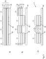
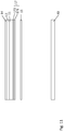
- Fig. 1A shows a transfer film 1 with a base film 10 and a further carrier film 40.
- the base film 10 comprises a carrier film 11, a release layer 12 and a decorative layer 13, which can comprise a protective lacquer layer, a replication lacquer layer, a reflection layer and an adhesive layer 14.
- a reinforcement layer with a layer thickness of approximately 0.1 ⁇ m to 5 ⁇ m, preferably of 1 ⁇ m to 3 ⁇ m can be provided for additional mechanical stabilization in the case of lamination, for example in a plastic card structure.
- a further reinforcement layer with a layer thickness of approximately 0.1 ⁇ m to 10 ⁇ m, preferably approximately 0.5 ⁇ m to 5 ⁇ m may be provided for additional mechanical stabilization in the case of a lamination, for example in a plastic card structure.
- These aforementioned reinforcement layers can also be constructed in multiple layers.
- the carrier film 11 is preferably a PET, PEN or BOPP film with a thickness of 6 ⁇ m to 125 ⁇ m.
- the release layer and the decorative layer are then built up one after the other on the carrier film 11 by applying further layers.
- the release layer 12 is first applied to the carrier film 11.
- the release layer 12 preferably consists of a wax-like material, which is softened in particular by the heat occurring during a hot stamping process and enables the decorative layer to be reliably separated from the carrier film 11.
- the release layer can be constructed in several layers (for example from a layer of wax and then a layer of release lacquer).
- the total thickness of the release layer is preferably between 0.01 ⁇ m to 1.2 ⁇ m.
- the protective lacquer layer is then applied in a layer thickness between 0.5 ⁇ m and 1.5 ⁇ m. It is also possible here for the protective lacquer layer to take over the function of the release layer 12 and accordingly to enable the decorative layer 13 to be separated from the carrier film 11 and also to protect the decorative layer 13 from mechanical influences and environmental influences. It is also possible that the protective lacquer layer 13 is colored or contains micro- and nano-particles.
- the replication lacquer layer consists of a thermoplastic lacquer in which a surface structure is molded by means of heat and pressure through the action of an embossing tool. Furthermore, it is also possible for the replication lacquer layer to be formed by a UV-crosslinkable lacquer and for the surface structure to be molded into the replication lacquer layer by means of UV replication.
- the replication lacquer layer preferably has a layer thickness between 0.5 ⁇ m and 15 ⁇ m.
- the surface structure molded into the replication lacquer layer is preferably a diffractive surface structure, for example a hologram, Kinegram® or some other diffraction-optically active grating structure.
- Such surface structures usually have a spacing of the structural elements in the range from 0.1 ⁇ m to 4 ⁇ m. It is further it is also possible for the surface structure to be a macroscopic surface structure, for example a microlens field or a blaze grating.
- the reflection layer is applied to the replication lacquer layer.
- the reflection layer is preferably a metal layer made of chromium, copper, silver or gold or an alloy of such metals, which is evaporated in a vacuum in a layer thickness of 0.01 ⁇ m to 0.10 ⁇ m.
- Such a dielectric reflection layer consists, for example, of a vapor-deposited layer made of a metal oxide, metal sulfide, titanium dioxide, etc. with a thickness of 10 nm to 150 nm.
- the decorative layer 13 can comprise one or more electrically conductive or semiconductor layers which implement an electrical circuit or an electrical component, for example an RF resonance circuit or an RFID tag.
- This can be a metallic layer, for example, which is either vapor-deposited or printed on and then reinforced by galvanic growth.
- the reflection layer 16 can simultaneously serve as an electrically conductive layer, which can also be galvanically amplified for this purpose.
- the decorative layer 13 can comprise one or more layers made of a magnetic material or an electroluminescent material.
- the adhesive layer 14 which can be constructed in multiple layers and / or on an aqueous or solvent-based basis and / or radiation-curing or combinations thereof, is applied in a total layer thickness of approximately 0.3 ⁇ m to 25 ⁇ m.
- the adhesive layer 14 preferably consists of a thermally activatable adhesive and is applied to the entire surface of the layer 13, for example by means of a doctor blade.
- an adhesive layer 15 is applied, which preferably also consists of a thermally activatable adhesive and is applied over the entire surface.
- the base film 10 and thus also the decorative layer 13 has two first partial areas 21 and a second partial area 22 surrounding the first partial areas 21.
- the first partial areas represent the part of the decorative layer which is to be transferred as a security element to a target substrate, for example a security document.
- the relief structure molded into the replication lacquer layer is preferably selected such that it generates predetermined optically variable information in the first partial regions 21.
- the surface structure molded in the first partial areas 21 thus preferably differs from the surface structure molded in the partial area 22 in the replication lacquer layer.
- the reflection layer is preferably provided in the form of a pattern and partially and provides second predefined information in the first partial regions 21.
- the pattern-like configuration of the reflection layer in the first partial regions 21 thus preferably also differs from that in the second partial region 22.
- the reflective layer is preferably not provided in the second partial region 22.
- the optional further optically active layers of the decorative layer 13 are also preferably formed in register with respect to the partial areas 21 and provide further information in the partial areas 21, so that the molding takes place this layer also differs in the first partial regions 21 from that in the second partial region 22.
- first partial regions 21 are provided which are enclosed by a continuous second partial region 22 which surrounds the first partial regions 21.
- a first adhesive layer 30 is applied to the further carrier film 40.
- the adhesive layer 30 is applied only in the area of the first partial areas 21 and preferably in a grid.
- the adhesive layer 30 is a UV-activatable adhesive.
- the adhesive that can be used for the adhesive layer 30 has the following composition, for example: Dicyclopentyloxyethyl methacrylate 50% to 60% 2-hydroxyethyl methacrylate 8th% trimethylolpropane 40% to 30% (3- (2,3-epoxypropoxy) propyl) trimethoxysilane 1% 1-hydroxy-cyclohexyl-phenyl-ketone (Irgacure 184 (BASF)) 1 to 2%
- composition that can be used for the adhesive layer 30 is, for example: Dicyclopentyloxyethyl methacrylate 50% to 55% 2-hydroxyethyl methacrylate 8th% trimethylolpropane 35% to 30% Phenol, ethoxylated, esters with acrylic acid 5% Dipropyleneglycoldiacrylate 5% (3- (2,3-epoxypropoxy) propyl) trimethoxysilane 1% 1-hydroxycyclohexylphenyl ketone (Irgacure 184 (BASF)) 1 to 2%
- the adhesive layer 30 is applied to the carrier film 40 in a layer thickness of 0.1 ⁇ m to 10 ⁇ m by means of a printing process, by means of casting or by means of a doctor blade.
- the carrier film 40 is a transparent plastic film which preferably consists of PET, PVC, PEN or BOPP film and has a layer thickness of 6 ⁇ m to 250 ⁇ m.
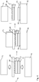
- the production of the transfer film 1 is illustrated step by step. How Figure 2A shows, the base film 10 is first provided without the adhesive layers 14 and 15, which are applied in the following process step. After the adhesive layers 14 and 15 have been dried, the transfer film 40 is connected to the base film via the adhesive layer 30.
- the adhesive layer 30 can be applied to the transfer film 40 or to the adhesive layer 15. It is possible and preferred to apply the adhesive layer 30 only in the region 21.
- the adhesive layer 30 can also be applied over the entire surface and activated only in the region 21.
- a first area of the adhesive layer 30 is activated by exposure.
- the in Figure 2C shown film structure consisting of the carrier film 40, the adhesive layer 30, the carrier film 11, the release layer 12 and the decorative layer 13, exposed in the region 31 with UV light.
- a collimated light source is used, which is spaced on the side of the carrier film 40 facing away from the carrier film 11 and at a distance from the carrier film 40.
- an exposure mask is arranged in the beam path between the light source and the adhesive layer 30, which covers the area 32 and thus enables selective exposure of the area 31.
- the exposure source and the exposure mask are preferably part of a drum imagesetter via which the Foil body is guided.
- the exposure mask is shaped and arranged in such a way that the area 31 largely covers the first partial areas 21 and is positioned within a register tolerance of preferably 0.1 mm to 2.0 mm to the first partial areas 21.
- the adhesive layer 30 is not exposed to UV light and is therefore not activated.
- the UV adhesive is preferably radically UV-curing and therefore has a solids content of 100%. A fraction of monomers can also evaporate during UV curing because heat is also introduced into the layer by the UV radiation if the adhesive is not completely enclosed between two adjacent layers, in particular foils.
- the heat sealable adhesive consists of acrylates and solvents (isopropanol + toluene).
- the solids content is 19% to 20% to ensure the application to the painting machine. It has a non-sticky surface at room temperature (approx. 20 ° C) after drying, especially at room temperature, since neither the melting point nor the glass transition temperature are below 30 ° C and therefore always above the processing (manufacturing) temperature of the film.
- the decorative layer 13, the release layer 12 and the carrier film 11 are severed along the boundary lines defining the first partial regions 21 and separating the first partial regions 21 from the partial region 22.
- These layers are preferably severed by means of a punch which has corresponding recesses in the Introduces layers 30 and 15 to 11 existing film body. It is also possible that the punching depth is selected so that the carrier film 40 is also partially cut. Furthermore, it is also possible that the carrier film 11 is not completely, but only partially severed. On the one hand, this can be done in such a way that regions alternate along the boundary line in which the carrier film 11 is completely cut or not cut or that the carrier film 11 is not cut in its entire thickness, but only, for example, in 80% of its thickness.
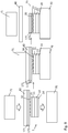
- the multilayer body 1 can be used as a transfer film for applying a security element 23 to a target substrate 70.
- the multilayer body 1 is placed on the target substrate 70 and the adhesive layers 14 and 15 are activated in a first partial area by an appropriately shaped hot stamp 71.
- the adhesive layer 14 By activating the adhesive layer 14, the transfer layer of the multilayer body 1 is connected to the target substrate 70.
- the adhesive layer 15 is activated, which increases the adhesion between the carrier layers 11 and 40, preferably by more than 50%, preferably more than 100%, particularly preferably more than 200%.
- the embossing takes place at a temperature from 80 ° C. to 300 ° C., preferably from 100 ° C. to 240 ° C., particularly preferably from 100 ° C. to 180 ° C. and / or with a Embossing pressure from 10 N / cm 2 to 10000 N / cm 2 , preferably from 100 N / cm 2 to 5000 N / cm 2 and / or with an embossing time from 0.01s to 2s.
- the multilayer body comprising the carrier film 40, the adhesive layer 30 and the carrier film 11 is then pulled off the applied area of the decorative layer 13, so that the security element 23 remains on the target substrate 70, as shown in FIG Fig. 4 is shown.
- Activation of the adhesive layer 15 ensures that no carrier film remains on the security element 23.
- the decorative layer comprises an optional protective lacquer layer 131 with a preferred layer thickness of 0.1 ⁇ m to 20 ⁇ m, particularly preferably from 0.5 ⁇ m to 10 ⁇ m, a replication lacquer layer with a preferred layer thickness of 0.1 ⁇ m to 10 ⁇ m, particularly preferably from 0 .5 ⁇ m to 5 ⁇ m with reflection layer 132, a primer lacquer layer 133 with a preferred layer thickness of 0.1 ⁇ m to 5 ⁇ m, particularly preferably from 1 ⁇ m to 3v, a volume hologram layer 134 with a preferred layer thickness of 5 ⁇ m to 50 ⁇ m, particularly preferred from 10 ⁇ m to 20 ⁇ m and a sealing wax layer 135 with a preferred layer thickness of 0.1 ⁇ m to 5 ⁇ m, particularly preferably from 5 ⁇ m to 15 ⁇ m.
- a volume hologram is written into the volume hologram layer 134, which forms the essential security feature of the resulting security element 32.
- the decorative layer 13 consists of a pressure-imparting layer 136 with a preferred layer thickness of 1 ⁇ m to 30 ⁇ m, particularly preferably from 1 ⁇ m to 3 ⁇ m, to which an individualization feature can be applied by ink jet printing.
- This layer 136 can also be used with all others already described layers of the decorative layer 13 can be combined in order to create an individualized security element 23.
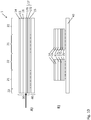
- FIGs 7A and 7B a schematic sectional illustration of a further transfer film 1 is shown.
- a release system 17 is provided on the second carrier film 40.
- the detachment system 17 makes it possible for the first carrier film 11 to remain on the security element 23 or in its layer composite when the security element 23 is applied.
- a self-supporting security element 23 can be produced, which for example can close or cover recesses, in particular window openings, in the target substrate 70.
- the additional mechanical stability that the first carrier film 11 gives to the security element 23 can serve to increase the optical brilliance of the security element 23 when the security element 23 is laminated, for example, in a plastic composite, as is the case, for example, with security documents made of polycarbonate (PC). in the ID card format or other laminates.
- PC polycarbonate
- This additional mechanical stability can also be advantageous when the target substrate 70 is processed further, for example when overprinting with a steel engraving.
- the in Figure 7A The arrow shown shows the position of the separation when the transfer film 1 is applied to a target substrate 70.
- the base film 10 is preferably designed here as a laminating film.
- the total thickness of the stripping system 17 is preferably between 0.01 ⁇ m to 4 ⁇ m.
- the release system 17 preferably has a layer of wax 171.
- the wax-like material is softened by the heat occurring during a hot stamping process and enables the second carrier film 40 to be reliably separated.
- the release system 17 may further comprise a layer of a varnish 172.
- the varnishes 172 are preferably based on acrylates, polyurethanes or cellulose derivatives.
- the lacquer layer 172 preferably has a thickness in the range from 0.1 to 3 ⁇ m, preferably in the range from 0.2 to 1.5 ⁇ m.
- Figure 8 shows a possible production of the transfer film 1.
- the release system 17 in particular consisting of a wax layer 171 which adjoins the second carrier film 40 and a lacquer layer 172, is applied to the second carrier layer 40.
- the base film 10 preferably has the adhesive layer 14, the decorative layer 13 and the first carrier film 11 and the adhesive layer 15.
- the Figure 9 shows the at least area-wise application of the transfer film 1 to a target substrate 70.
- the transfer film 1 is placed on the target substrate 70 and the adhesive layers 14 and 15 are activated in a first partial area 21 by an appropriately shaped hot stamp 71.
- the adhesive layer 14 By activating the adhesive layer 14, the transfer layer of the transfer film 1 is connected to the target substrate 70.
- the adhesive layer 15 is activated, which increases the adhesion between the first carrier layer 11 and the release system 17.
- the wax layer 171 softening during the application of heat also ensures a clean separation between the release system 17 and the second carrier film 40.
- the detachment system 17 remains together with the first carrier film 11 and the decorative layer 13, preferably as a security element 23, after application to the target substrate 70. Since the detachment system 17 forms the outer surface of the security element 23 and can be configured in a wide variety of ways, the security element can thereby be designed can be equipped with additional functions. Examples are better wettability or overprintability with further functional layers or, on the contrary, a hydrophobic function or other functions that repel liquids, or also the production of an optical matting and / or an optical gloss and / or the production of special tactile properties. It is also possible, to supplement additional security prints in the visible wavelength range, UV range, IR range. Individual or all layers of the release layer system can be provided over the entire surface or only in partial surface areas.
- FIGS 10A and 10B a schematic sectional illustration of a further transfer film 1 is shown.
- a release system 17 is provided on the first carrier film 11.
- the detachment system 17 makes it possible for the first carrier film 11 to remain on the security element 23 or in its layer composite when the security element 23 is applied.
- a self-supporting security element 23 can be produced, which can, for example, close or cover recesses, in particular window openings, in the target substrate 70.
- the additional mechanical stability that the first carrier film 11 gives to the security element 23 can serve to increase the optical brilliance of the security element 23 when the security element 23 is laminated, for example, in a plastic composite, as is the case, for example, with security documents made of polycarbonate (PC). in the ID card format or other laminates.
- PC polycarbonate
- This additional mechanical stability can also be advantageous when the target substrate 70 is processed further, for example when overprinting with a steel engraving.
- the in Figure 10A The arrow shown shows the position of the separation when the transfer film is applied to a target substrate 70.
- the base film 10 is preferably designed here as a laminating film.
- the total thickness of the stripping system 17 is preferably between 0.01 ⁇ m to 4 ⁇ m.
- the release system 17 preferably has a layer of wax 171.
- the wax-like material is softened by the heat occurring during a hot stamping process and enables the second carrier film 40 to be reliably separated.
- the release system 17 may further comprise a layer of a varnish 172.
- the paint 172 is preferably based on acrylates, polyurethanes or cellulose derivatives.
- the lacquer layer 172 preferably has a thickness in the range from 0.1 to 3 ⁇ m, preferably in the range from 0.2 to 1.5 ⁇ m.
- Figure 11 shows a possible production of the transfer film 1.
- the release system 17 is applied to the side of the first carrier film 11 of the base film 10 facing away from the decorative layer 13.
- the release system 17 can have a wax layer 171 and a lacquer layer 172.
- the adhesive layer 15 is then preferably applied to the outer, free side of the release system 17.
- the adhesive layer 15 is preferably in contact with the adhesive layer 30.
- This embodiment variant can also make it possible for the base film 10 to remain on the security element 23 or in its layer composite when the security element 23 is applied. As a result, a self-supporting security element 23 can be produced, which for example can close or cover recesses, in particular window openings, in the target substrate.
- auxiliary layers (not shown) to be applied to the side of the first carrier film 11 of the base film 10 facing away from the decorative layer 13, which are then arranged between the first carrier film 11 and the release system 17, before the release system 17 is applied .
- the Figure 12 shows the at least partial application of the transfer film 1 to a target substrate 70.
- the transfer film 1 is placed on the target substrate 70.
- the adhesive layer 14 By activating the adhesive layer 14, the transfer layer of the transfer film 1 is connected to the target substrate 70.
- the wax layer softened during application by the action of heat 171 ensures a clean separation between the release system 17 and the first carrier film 11.
- the detachment system 17 is detached from the security element 23 after application to the target substrate 70. If auxiliary layers are arranged between the detachment system 17 and the first carrier film 11, the auxiliary layers form the outer, free surface of the security element 23. If these auxiliary layers are dispensed with, the carrier film 11 forms the outer, free surface of the security element 23 and thus allows a particularly brilliant optical effect of the security element 23.
Landscapes
- Engineering & Computer Science (AREA)
- Manufacturing & Machinery (AREA)
- General Health & Medical Sciences (AREA)
- Chemical & Material Sciences (AREA)
- Chemical Kinetics & Catalysis (AREA)
- General Chemical & Material Sciences (AREA)
- Health & Medical Sciences (AREA)
- Toxicology (AREA)
- Decoration By Transfer Pictures (AREA)
- Laminated Bodies (AREA)
- Credit Cards Or The Like (AREA)
- Holo Graphy (AREA)
- Impression-Transfer Materials And Handling Thereof (AREA)
Priority Applications (4)
| Application Number | Priority Date | Filing Date | Title |
|---|---|---|---|
| SI201630650T SI3390069T1 (sl) | 2015-12-15 | 2016-12-13 | Postopek za izdelavo zaščitnega elementa in prenosna folija |
| RS20200241A RS60018B1 (sr) | 2015-12-15 | 2016-12-13 | Postupak za izradu sigurnosnog elementa kao i prenosna folija |
| PL16816247T PL3390069T3 (pl) | 2015-12-15 | 2016-12-13 | Sposób wytwarzania elementu zabezpieczającego oraz folia transferowa |
| HRP20200639TT HRP20200639T1 (hr) | 2015-12-15 | 2016-12-13 | Postupak za proizvodnju sigurnosnog elementa i transferne folije |
Applications Claiming Priority (2)
| Application Number | Priority Date | Filing Date | Title |
|---|---|---|---|
| DE102015121849.6A DE102015121849A1 (de) | 2015-12-15 | 2015-12-15 | Verfahren zur Herstellung eines Sicherheitselements sowie Transferfolie |
| PCT/EP2016/080825 WO2017102744A1 (de) | 2015-12-15 | 2016-12-13 | Verfahren zur herstellung eines sicherheitselements sowie transferfolie |
Publications (2)
| Publication Number | Publication Date |
|---|---|
| EP3390069A1 EP3390069A1 (de) | 2018-10-24 |
| EP3390069B1 true EP3390069B1 (de) | 2020-01-15 |
Family
ID=57590503
Family Applications (1)
| Application Number | Title | Priority Date | Filing Date |
|---|---|---|---|
| EP16816247.7A Active EP3390069B1 (de) | 2015-12-15 | 2016-12-13 | Verfahren zur herstellung eines sicherheitselements sowie transferfolie |
Country Status (21)
| Country | Link |
|---|---|
| US (1) | US11124011B2 (enExample) |
| EP (1) | EP3390069B1 (enExample) |
| JP (1) | JP6938504B2 (enExample) |
| KR (1) | KR102628765B1 (enExample) |
| CN (1) | CN108367587B (enExample) |
| AU (1) | AU2016369289B2 (enExample) |
| BR (1) | BR112018011594B8 (enExample) |
| DE (1) | DE102015121849A1 (enExample) |
| DK (1) | DK3390069T3 (enExample) |
| ES (1) | ES2774508T3 (enExample) |
| HR (1) | HRP20200639T1 (enExample) |
| HU (1) | HUE048866T2 (enExample) |
| MX (1) | MX2018007174A (enExample) |
| MY (1) | MY187805A (enExample) |
| PH (1) | PH12018501196B1 (enExample) |
| PL (1) | PL3390069T3 (enExample) |
| PT (1) | PT3390069T (enExample) |
| RS (1) | RS60018B1 (enExample) |
| RU (1) | RU2709924C1 (enExample) |
| SI (1) | SI3390069T1 (enExample) |
| WO (1) | WO2017102744A1 (enExample) |
Families Citing this family (24)
| Publication number | Priority date | Publication date | Assignee | Title |
|---|---|---|---|---|
| FR3012651B1 (fr) * | 2013-10-24 | 2017-03-31 | Cevenpack | Etiquette d'ornement d'une bouteille, bouteille et procede de fabrication d'une telle etiquette |
| DE102018001379A1 (de) * | 2018-02-21 | 2019-08-22 | Giesecke+Devrient Currency Technology Gmbh | Transferträger |
| DE102018105735A1 (de) | 2018-03-13 | 2019-09-19 | Mitsubishi Polyester Film Gmbh | Trennfolie für Tiefdruckanwendung |
| DE102018002306A1 (de) * | 2018-03-21 | 2019-09-26 | Giesecke+Devrient Currency Technology Gmbh | Verfahren zum Herstellen eines Sicherheitselement-Transfermaterials und Sicherheitselement-Transfermaterial |
| CA3098282A1 (en) * | 2018-05-25 | 2019-11-28 | Ovd Kinegram Ag | Method for producing a laminated body and a laminating film and laminated body and laminating film |
| DE102018132321A1 (de) | 2018-12-14 | 2020-06-18 | Ovd Kinegram Ag | Verfahren zur Herstellung eines Folienzwischenprodukts, Folienzwischenprodukt sowie Verfahren zur Herstellung eines Produkts |
| DE102018222669A1 (de) * | 2018-12-20 | 2020-06-25 | Bundesdruckerei Gmbh | Verfahren zum Herstellen eines Wert- oder Sicherheitsdokuments oder eines Wert- oder Sicherheitsdokumentenrohlings und Wert- oder Sicherheitsdokument |
| DE102019104174A1 (de) * | 2019-02-19 | 2020-08-20 | Ovd Kinegram Ag | Mehrschichtkörper sowie Verfahren zur Herstellung eines Mehrschichtkörpers |
| EP3726507B1 (de) * | 2019-04-19 | 2021-05-26 | Securikett Ulrich & Horn GmbH | Versiegelungsfolie |
| CN110163159B (zh) * | 2019-05-24 | 2021-09-03 | 上海思立微电子科技有限公司 | 屏下指纹识别结构的准直器贴合方法 |
| GB2587806B (en) * | 2019-09-30 | 2022-12-21 | De La Rue Int Ltd | A method for manufacturing a security substrate |
| DE102019006977A1 (de) * | 2019-10-08 | 2021-04-08 | Giesecke+Devrient Currency Technology Gmbh | Sicherheitselement- Transfermaterial, Verfahren zum Herstellen desselben und Verwendung |
| DE102019132787A1 (de) * | 2019-12-03 | 2021-06-10 | Leonhard Kurz Stiftung & Co. Kg | Dekorfolie, Verfahren zur Herstellung einer Dekorfolie und Verfahren zur Dekoration eines Zielsubstrats |
| CN114007858B (zh) * | 2020-02-17 | 2025-02-21 | 米岛毛毡产业株式会社 | 层叠材料、中间片材的制造方法以及复合材料的制造方法 |
| DE102020121896A1 (de) * | 2020-08-20 | 2022-02-24 | Leonhard Kurz Stiftung & Co. Kg | Mehrschichtkörper und ein Verfahren zur Herstellung eines Mehrschichtköpers |
| DE102020005769A1 (de) | 2020-09-21 | 2022-03-24 | Giesecke+Devrient Currency Technology Gmbh | Sicherheitselement-Transfermaterial zur registerhaltigen Übertragung von Sicherheitselementen auf Wertdokumente |
| KR20230015442A (ko) * | 2020-10-15 | 2023-01-31 | 요네시마펠트 씨오., 엘티디. | 긴 발포체시트의 제조방법, 복합재의 제조방법 및 긴 발포체시트 |
| CN112185237B (zh) * | 2020-10-28 | 2025-03-14 | 武汉华工图像技术开发有限公司 | 一种加密数码标识及其制备方法 |
| DE102021100319A1 (de) | 2021-01-11 | 2022-07-14 | Mühlbauer Gmbh & Co. Kg | Verfahren zum herstellen eines mehrschichtigen laminierten dokumentensubstrats mit einem einlegekörper |
| DE102021003009A1 (de) * | 2021-06-11 | 2022-12-15 | Sartorius Stedim Biotech Gmbh | Produkt zum Bereitstellen von Membranelementen und Herstellungsverfahren |
| HUP2200387A1 (hu) * | 2022-09-28 | 2024-04-28 | Penzjegynyomda Zrt | Eljárás és berendezés többrétegû, ablakelemmel ellátott kártya elõállítására, valamint ilyen kártya |
| FR3141639B1 (fr) * | 2022-11-03 | 2024-09-20 | Surys | Dispositif optique de sécurité |
| DE102023119166B3 (de) * | 2023-07-20 | 2024-10-17 | Giesecke+Devrient Currency Technology Gmbh | Transferaufbau |
| FR3156697A1 (fr) * | 2023-12-18 | 2025-06-20 | Wormsensing | Substrat flexible à empilement de couches support et de couches adhésives |
Family Cites Families (11)
| Publication number | Priority date | Publication date | Assignee | Title |
|---|---|---|---|---|
| US5006047A (en) | 1989-02-27 | 1991-04-09 | Thomas Industries, Inc. | Compressor with a segmented piston rod assembly |
| US5066047A (en) * | 1990-09-05 | 1991-11-19 | Polaroid Corporation | Process for incorporating hologram into laminar structure with photograph |
| DE19940790B4 (de) * | 1999-08-27 | 2004-12-09 | Leonhard Kurz Gmbh & Co | Übertragungsfolie zur Aufbringung einer Dekorschichtanordnung auf ein Substrat sowie Verfahren zu deren Herstellung |
| DE10233452B4 (de) | 2002-07-24 | 2006-08-17 | Ovd Kinegram Ag | Individualisiertes Sicherheitsdokument |
| DE10343547A1 (de) * | 2003-09-19 | 2005-04-14 | Giesecke & Devrient Gmbh | Sicherheitselement |
| DE102004042136B4 (de) | 2004-08-30 | 2006-11-09 | Ovd Kinegram Ag | Metallisiertes Sicherheitselement |
| DE102005017170B4 (de) * | 2005-04-13 | 2010-07-01 | Ovd Kinegram Ag | Transferfolie, Verfahren zu deren Herstellung sowie Mehrschichtkörper und dessen Verwendung |
| EP1940618B1 (de) * | 2005-10-27 | 2016-08-17 | OVD Kinegram AG | Verfahren zum transfer eines mehrschichtkörpers sowie transferfolie |
| FR2897556B1 (fr) | 2006-02-23 | 2008-05-23 | Fasver Soc Par Actions Simplif | Film de transfert d'au moins une marque sur au moins un substrat a securiser, procede de fabrication et de transfert d'un tel film de transfert. |
| EP2163398A1 (de) * | 2008-09-12 | 2010-03-17 | DeMaxZ AG | Technik zum Aufbringen einer lösbar an einem Trägerfilm haftenden Dekorschicht auf ein Objekt |
| DE102008062149B3 (de) * | 2008-12-16 | 2010-04-29 | Ovd Kinegram Ag | Verfahren zur Herstellung eines Sicherheitselements sowie Transferfolie |
-
2015
- 2015-12-15 DE DE102015121849.6A patent/DE102015121849A1/de not_active Ceased
-
2016
- 2016-12-13 KR KR1020187018462A patent/KR102628765B1/ko active Active
- 2016-12-13 EP EP16816247.7A patent/EP3390069B1/de active Active
- 2016-12-13 HU HUE16816247A patent/HUE048866T2/hu unknown
- 2016-12-13 CN CN201680073106.1A patent/CN108367587B/zh active Active
- 2016-12-13 HR HRP20200639TT patent/HRP20200639T1/hr unknown
- 2016-12-13 US US16/061,199 patent/US11124011B2/en active Active
- 2016-12-13 DK DK16816247.7T patent/DK3390069T3/da active
- 2016-12-13 SI SI201630650T patent/SI3390069T1/sl unknown
- 2016-12-13 RS RS20200241A patent/RS60018B1/sr unknown
- 2016-12-13 BR BR112018011594A patent/BR112018011594B8/pt active IP Right Grant
- 2016-12-13 PL PL16816247T patent/PL3390069T3/pl unknown
- 2016-12-13 ES ES16816247T patent/ES2774508T3/es active Active
- 2016-12-13 MY MYPI2018000907A patent/MY187805A/en unknown
- 2016-12-13 AU AU2016369289A patent/AU2016369289B2/en active Active
- 2016-12-13 WO PCT/EP2016/080825 patent/WO2017102744A1/de not_active Ceased
- 2016-12-13 JP JP2018531564A patent/JP6938504B2/ja active Active
- 2016-12-13 PT PT168162477T patent/PT3390069T/pt unknown
- 2016-12-13 MX MX2018007174A patent/MX2018007174A/es unknown
- 2016-12-13 RU RU2018123691A patent/RU2709924C1/ru active
-
2018
- 2018-06-06 PH PH12018501196A patent/PH12018501196B1/en unknown
Non-Patent Citations (1)
| Title |
|---|
| None * |
Also Published As
| Publication number | Publication date |
|---|---|
| WO2017102744A1 (de) | 2017-06-22 |
| CA3007154A1 (en) | 2017-06-22 |
| PH12018501196B1 (en) | 2021-12-01 |
| DK3390069T3 (da) | 2020-04-14 |
| CN108367587B (zh) | 2020-12-15 |
| PH12018501196A1 (en) | 2019-01-28 |
| AU2016369289A1 (en) | 2018-06-21 |
| CN108367587A (zh) | 2018-08-03 |
| EP3390069A1 (de) | 2018-10-24 |
| KR102628765B1 (ko) | 2024-01-24 |
| RU2709924C1 (ru) | 2019-12-23 |
| MX2018007174A (es) | 2018-08-01 |
| SI3390069T1 (sl) | 2020-04-30 |
| US11124011B2 (en) | 2021-09-21 |
| HUE048866T2 (hu) | 2020-08-28 |
| KR20180093960A (ko) | 2018-08-22 |
| ES2774508T3 (es) | 2020-07-21 |
| AU2016369289B2 (en) | 2021-04-22 |
| BR112018011594B8 (pt) | 2023-02-14 |
| HRP20200639T1 (hr) | 2020-07-10 |
| PL3390069T3 (pl) | 2020-07-27 |
| RS60018B1 (sr) | 2020-04-30 |
| BR112018011594A2 (pt) | 2018-11-21 |
| MY187805A (en) | 2021-10-26 |
| BR112018011594B1 (pt) | 2022-11-08 |
| JP2019505410A (ja) | 2019-02-28 |
| JP6938504B2 (ja) | 2021-09-22 |
| DE102015121849A1 (de) | 2017-06-22 |
| US20190001735A1 (en) | 2019-01-03 |
| PT3390069T (pt) | 2020-04-22 |
Similar Documents
| Publication | Publication Date | Title |
|---|---|---|
| EP3390069B1 (de) | Verfahren zur herstellung eines sicherheitselements sowie transferfolie | |
| EP2373492B1 (de) | Verfahren zur herstellung eines sicherheitselements sowie transferfolie | |
| EP3183124B1 (de) | Transferfolie sowie verfahren zur herstellung einer transferfolie | |
| EP2344343B1 (de) | Sicherheitselement-transfermaterial mit mehrschichtigem träger | |
| EP1940618B1 (de) | Verfahren zum transfer eines mehrschichtkörpers sowie transferfolie | |
| EP3668719B1 (de) | Dokument und verfahren zur herstellung eines dokuments | |
| EP3802144B1 (de) | Verfahren zur herstellung eines laminatkörpers und einer laminierfolie sowie laminatkörper und laminierfolie | |
| EP3600907B1 (de) | Verfahren zum herstellen einer mehrschichtfolie und eine mehrschichtfolie sowie ein sicherheitselement und ein sicherheitsdokument | |
| EP2981419B1 (de) | Verfahren zum herstellen eines sicherheitselements mit negativschrift | |
| DE102018112652A1 (de) | Verfahren zur Herstellung eines Laminatkörpers und einer Laminierfolie sowie Laminatkörper und Laminierfolie | |
| EP3894232B1 (de) | Verfahren zur herstellung eines folienzwischenprodukts, folienzwischenprodukt sowie verfahren zur herstellung eines produkts | |
| DE202017103832U1 (de) | Transferfolie, Laminierfolie und Folienelement | |
| EP3747666A1 (de) | Applikationsvorrichtung zum applizieren einer übertragungslage einer folie auf einen körper und mehrschichtkörper | |
| EP3927561A1 (de) | Mehrschichtkörper sowie verfahren zur herstellung eines mehrschichtkörpers | |
| CA3007154C (en) | Method for producing a security element and transfer film | |
| EP4230426A1 (de) | Sicherheitselement-transfermaterial und verfahren zum herstellen desselben |
Legal Events
| Date | Code | Title | Description |
|---|---|---|---|
| STAA | Information on the status of an ep patent application or granted ep patent |
Free format text: STATUS: UNKNOWN |
|
| STAA | Information on the status of an ep patent application or granted ep patent |
Free format text: STATUS: THE INTERNATIONAL PUBLICATION HAS BEEN MADE |
|
| PUAI | Public reference made under article 153(3) epc to a published international application that has entered the european phase |
Free format text: ORIGINAL CODE: 0009012 |
|
| STAA | Information on the status of an ep patent application or granted ep patent |
Free format text: STATUS: REQUEST FOR EXAMINATION WAS MADE |
|
| 17P | Request for examination filed |
Effective date: 20180711 |
|
| AK | Designated contracting states |
Kind code of ref document: A1 Designated state(s): AL AT BE BG CH CY CZ DE DK EE ES FI FR GB GR HR HU IE IS IT LI LT LU LV MC MK MT NL NO PL PT RO RS SE SI SK SM TR |
|
| AX | Request for extension of the european patent |
Extension state: BA ME |
|
| STAA | Information on the status of an ep patent application or granted ep patent |
Free format text: STATUS: EXAMINATION IS IN PROGRESS |
|
| 17Q | First examination report despatched |
Effective date: 20190201 |
|
| DAV | Request for validation of the european patent (deleted) | ||
| DAX | Request for extension of the european patent (deleted) | ||
| RAP1 | Party data changed (applicant data changed or rights of an application transferred) |
Owner name: OVD KINEGRAM AG |
|
| GRAP | Despatch of communication of intention to grant a patent |
Free format text: ORIGINAL CODE: EPIDOSNIGR1 |
|
| STAA | Information on the status of an ep patent application or granted ep patent |
Free format text: STATUS: GRANT OF PATENT IS INTENDED |
|
| INTG | Intention to grant announced |
Effective date: 20191107 |
|
| GRAS | Grant fee paid |
Free format text: ORIGINAL CODE: EPIDOSNIGR3 |
|
| GRAA | (expected) grant |
Free format text: ORIGINAL CODE: 0009210 |
|
| STAA | Information on the status of an ep patent application or granted ep patent |
Free format text: STATUS: THE PATENT HAS BEEN GRANTED |
|
| AK | Designated contracting states |
Kind code of ref document: B1 Designated state(s): AL AT BE BG CH CY CZ DE DK EE ES FI FR GB GR HR HU IE IS IT LI LT LU LV MC MK MT NL NO PL PT RO RS SE SI SK SM TR |
|
| REG | Reference to a national code |
Ref country code: CH Ref legal event code: EP Ref country code: GB Ref legal event code: FG4D Free format text: NOT ENGLISH |
|
| REG | Reference to a national code |
Ref country code: CH Ref legal event code: NV Representative=s name: FIAMMENGHI-FIAMMENGHI, CH |
|
| REG | Reference to a national code |
Ref country code: IE Ref legal event code: FG4D Free format text: LANGUAGE OF EP DOCUMENT: GERMAN |
|
| REG | Reference to a national code |
Ref country code: AT Ref legal event code: REF Ref document number: 1224827 Country of ref document: AT Kind code of ref document: T Effective date: 20200215 |
|
| REG | Reference to a national code |
Ref country code: DE Ref legal event code: R096 Ref document number: 502016008485 Country of ref document: DE |
|
| REG | Reference to a national code |
Ref country code: NL Ref legal event code: FP |
|
| REG | Reference to a national code |
Ref country code: SE Ref legal event code: TRGR |
|
| REG | Reference to a national code |
Ref country code: RO Ref legal event code: EPE |
|
| REG | Reference to a national code |
Ref country code: HR Ref legal event code: TUEP Ref document number: P20200639 Country of ref document: HR |
|
| REG | Reference to a national code |
Ref country code: DK Ref legal event code: T3 Effective date: 20200406 |
|
| REG | Reference to a national code |
Ref country code: FI Ref legal event code: FGE |
|
| REG | Reference to a national code |
Ref country code: PT Ref legal event code: SC4A Ref document number: 3390069 Country of ref document: PT Date of ref document: 20200422 Kind code of ref document: T Free format text: AVAILABILITY OF NATIONAL TRANSLATION Effective date: 20200413 |
|
| REG | Reference to a national code |
Ref country code: GR Ref legal event code: EP Ref document number: 20200400686 Country of ref document: GR Effective date: 20200518 |
|
| REG | Reference to a national code |
Ref country code: HR Ref legal event code: T1PR Ref document number: P20200639 Country of ref document: HR |
|
| REG | Reference to a national code |
Ref country code: ES Ref legal event code: FG2A Ref document number: 2774508 Country of ref document: ES Kind code of ref document: T3 Effective date: 20200721 |
|
| REG | Reference to a national code |
Ref country code: LT Ref legal event code: MG4D |
|
| PG25 | Lapsed in a contracting state [announced via postgrant information from national office to epo] |
Ref country code: NO Free format text: LAPSE BECAUSE OF FAILURE TO SUBMIT A TRANSLATION OF THE DESCRIPTION OR TO PAY THE FEE WITHIN THE PRESCRIBED TIME-LIMIT Effective date: 20200415 |
|
| REG | Reference to a national code |
Ref country code: HU Ref legal event code: AG4A Ref document number: E048866 Country of ref document: HU |
|
| PG25 | Lapsed in a contracting state [announced via postgrant information from national office to epo] |
Ref country code: IS Free format text: LAPSE BECAUSE OF FAILURE TO SUBMIT A TRANSLATION OF THE DESCRIPTION OR TO PAY THE FEE WITHIN THE PRESCRIBED TIME-LIMIT Effective date: 20200515 Ref country code: LV Free format text: LAPSE BECAUSE OF FAILURE TO SUBMIT A TRANSLATION OF THE DESCRIPTION OR TO PAY THE FEE WITHIN THE PRESCRIBED TIME-LIMIT Effective date: 20200115 |
|
| REG | Reference to a national code |
Ref country code: DE Ref legal event code: R097 Ref document number: 502016008485 Country of ref document: DE |
|
| PG25 | Lapsed in a contracting state [announced via postgrant information from national office to epo] |
Ref country code: SK Free format text: LAPSE BECAUSE OF FAILURE TO SUBMIT A TRANSLATION OF THE DESCRIPTION OR TO PAY THE FEE WITHIN THE PRESCRIBED TIME-LIMIT Effective date: 20200115 Ref country code: LT Free format text: LAPSE BECAUSE OF FAILURE TO SUBMIT A TRANSLATION OF THE DESCRIPTION OR TO PAY THE FEE WITHIN THE PRESCRIBED TIME-LIMIT Effective date: 20200115 Ref country code: SM Free format text: LAPSE BECAUSE OF FAILURE TO SUBMIT A TRANSLATION OF THE DESCRIPTION OR TO PAY THE FEE WITHIN THE PRESCRIBED TIME-LIMIT Effective date: 20200115 Ref country code: EE Free format text: LAPSE BECAUSE OF FAILURE TO SUBMIT A TRANSLATION OF THE DESCRIPTION OR TO PAY THE FEE WITHIN THE PRESCRIBED TIME-LIMIT Effective date: 20200115 |
|
| PLBE | No opposition filed within time limit |
Free format text: ORIGINAL CODE: 0009261 |
|
| STAA | Information on the status of an ep patent application or granted ep patent |
Free format text: STATUS: NO OPPOSITION FILED WITHIN TIME LIMIT |
|
| 26N | No opposition filed |
Effective date: 20201016 |
|
| REG | Reference to a national code |
Ref country code: HR Ref legal event code: ODRP Ref document number: P20200639 Country of ref document: HR Payment date: 20201207 Year of fee payment: 5 |
|
| PG25 | Lapsed in a contracting state [announced via postgrant information from national office to epo] |
Ref country code: MC Free format text: LAPSE BECAUSE OF FAILURE TO SUBMIT A TRANSLATION OF THE DESCRIPTION OR TO PAY THE FEE WITHIN THE PRESCRIBED TIME-LIMIT Effective date: 20200115 |
|
| PG25 | Lapsed in a contracting state [announced via postgrant information from national office to epo] |
Ref country code: LU Free format text: LAPSE BECAUSE OF NON-PAYMENT OF DUE FEES Effective date: 20201213 |
|
| REG | Reference to a national code |
Ref country code: HR Ref legal event code: ODRP Ref document number: P20200639 Country of ref document: HR Payment date: 20211202 Year of fee payment: 6 |
|
| PG25 | Lapsed in a contracting state [announced via postgrant information from national office to epo] |
Ref country code: CY Free format text: LAPSE BECAUSE OF FAILURE TO SUBMIT A TRANSLATION OF THE DESCRIPTION OR TO PAY THE FEE WITHIN THE PRESCRIBED TIME-LIMIT Effective date: 20200115 |
|
| PG25 | Lapsed in a contracting state [announced via postgrant information from national office to epo] |
Ref country code: MK Free format text: LAPSE BECAUSE OF FAILURE TO SUBMIT A TRANSLATION OF THE DESCRIPTION OR TO PAY THE FEE WITHIN THE PRESCRIBED TIME-LIMIT Effective date: 20200115 Ref country code: AL Free format text: LAPSE BECAUSE OF FAILURE TO SUBMIT A TRANSLATION OF THE DESCRIPTION OR TO PAY THE FEE WITHIN THE PRESCRIBED TIME-LIMIT Effective date: 20200115 |
|
| REG | Reference to a national code |
Ref country code: HR Ref legal event code: ODRP Ref document number: P20200639 Country of ref document: HR Payment date: 20221202 Year of fee payment: 7 |
|
| REG | Reference to a national code |
Ref country code: HR Ref legal event code: ODRP Ref document number: P20200639 Country of ref document: HR Payment date: 20231204 Year of fee payment: 8 |
|
| PGFP | Annual fee paid to national office [announced via postgrant information from national office to epo] |
Ref country code: PT Payment date: 20241203 Year of fee payment: 9 |
|
| REG | Reference to a national code |
Ref country code: HR Ref legal event code: ODRP Ref document number: P20200639 Country of ref document: HR Payment date: 20241203 Year of fee payment: 9 |
|
| PGFP | Annual fee paid to national office [announced via postgrant information from national office to epo] |
Ref country code: DE Payment date: 20241126 Year of fee payment: 9 |
|
| PGFP | Annual fee paid to national office [announced via postgrant information from national office to epo] |
Ref country code: DK Payment date: 20241217 Year of fee payment: 9 |
|
| PGFP | Annual fee paid to national office [announced via postgrant information from national office to epo] |
Ref country code: NL Payment date: 20241217 Year of fee payment: 9 Ref country code: FI Payment date: 20241216 Year of fee payment: 9 Ref country code: PL Payment date: 20241008 Year of fee payment: 9 Ref country code: GR Payment date: 20241213 Year of fee payment: 9 Ref country code: BE Payment date: 20241216 Year of fee payment: 9 |
|
| PGFP | Annual fee paid to national office [announced via postgrant information from national office to epo] |
Ref country code: GB Payment date: 20241218 Year of fee payment: 9 |
|
| PGFP | Annual fee paid to national office [announced via postgrant information from national office to epo] |
Ref country code: FR Payment date: 20241217 Year of fee payment: 9 Ref country code: BG Payment date: 20241212 Year of fee payment: 9 |
|
| PGFP | Annual fee paid to national office [announced via postgrant information from national office to epo] |
Ref country code: HU Payment date: 20241210 Year of fee payment: 9 Ref country code: AT Payment date: 20241213 Year of fee payment: 9 |
|
| PGFP | Annual fee paid to national office [announced via postgrant information from national office to epo] |
Ref country code: CZ Payment date: 20241129 Year of fee payment: 9 Ref country code: HR Payment date: 20241203 Year of fee payment: 9 Ref country code: IE Payment date: 20241212 Year of fee payment: 9 |
|
| PGFP | Annual fee paid to national office [announced via postgrant information from national office to epo] |
Ref country code: RO Payment date: 20241204 Year of fee payment: 9 |
|
| PGFP | Annual fee paid to national office [announced via postgrant information from national office to epo] |
Ref country code: IT Payment date: 20241216 Year of fee payment: 9 Ref country code: RS Payment date: 20241203 Year of fee payment: 9 |
|
| PGFP | Annual fee paid to national office [announced via postgrant information from national office to epo] |
Ref country code: SE Payment date: 20241217 Year of fee payment: 9 |
|
| PGFP | Annual fee paid to national office [announced via postgrant information from national office to epo] |
Ref country code: MT Payment date: 20241217 Year of fee payment: 9 |
|
| PGFP | Annual fee paid to national office [announced via postgrant information from national office to epo] |
Ref country code: TR Payment date: 20241204 Year of fee payment: 9 |
|
| PGFP | Annual fee paid to national office [announced via postgrant information from national office to epo] |
Ref country code: SI Payment date: 20241203 Year of fee payment: 9 |
|
| PGFP | Annual fee paid to national office [announced via postgrant information from national office to epo] |
Ref country code: ES Payment date: 20250117 Year of fee payment: 9 |
|
| PGFP | Annual fee paid to national office [announced via postgrant information from national office to epo] |
Ref country code: CH Payment date: 20250101 Year of fee payment: 9 |