EP3389776B1 - Capteur médical implantable et système de fixation - Google Patents
Capteur médical implantable et système de fixation Download PDFInfo
- Publication number
- EP3389776B1 EP3389776B1 EP16867375.4A EP16867375A EP3389776B1 EP 3389776 B1 EP3389776 B1 EP 3389776B1 EP 16867375 A EP16867375 A EP 16867375A EP 3389776 B1 EP3389776 B1 EP 3389776B1
- Authority
- EP
- European Patent Office
- Prior art keywords
- implantable medical
- fixation
- medical device
- fixation members
- loop
- Prior art date
- Legal status (The legal status is an assumption and is not a legal conclusion. Google has not performed a legal analysis and makes no representation as to the accuracy of the status listed.)
- Active
Links
- 239000002775 capsule Substances 0.000 claims description 76
- 210000004204 blood vessel Anatomy 0.000 claims description 20
- 230000036772 blood pressure Effects 0.000 claims description 10
- 210000001147 pulmonary artery Anatomy 0.000 claims description 9
- 239000012528 membrane Substances 0.000 claims description 5
- 239000011295 pitch Substances 0.000 description 71
- 239000007943 implant Substances 0.000 description 22
- 239000000463 material Substances 0.000 description 12
- 230000000712 assembly Effects 0.000 description 8
- 238000000429 assembly Methods 0.000 description 8
- 230000007423 decrease Effects 0.000 description 8
- 230000002792 vascular Effects 0.000 description 7
- 230000017531 blood circulation Effects 0.000 description 6
- 238000010276 construction Methods 0.000 description 5
- 238000010168 coupling process Methods 0.000 description 5
- 230000006870 function Effects 0.000 description 5
- 230000008901 benefit Effects 0.000 description 4
- 230000000630 rising effect Effects 0.000 description 4
- 238000012546 transfer Methods 0.000 description 4
- 210000003484 anatomy Anatomy 0.000 description 3
- 230000000747 cardiac effect Effects 0.000 description 3
- 230000008878 coupling Effects 0.000 description 3
- 238000005859 coupling reaction Methods 0.000 description 3
- 238000004519 manufacturing process Methods 0.000 description 3
- 230000007246 mechanism Effects 0.000 description 3
- 230000002829 reductive effect Effects 0.000 description 3
- 230000001225 therapeutic effect Effects 0.000 description 3
- 210000001519 tissue Anatomy 0.000 description 3
- 238000003466 welding Methods 0.000 description 3
- 206010007558 Cardiac failure chronic Diseases 0.000 description 2
- RTAQQCXQSZGOHL-UHFFFAOYSA-N Titanium Chemical compound [Ti] RTAQQCXQSZGOHL-UHFFFAOYSA-N 0.000 description 2
- 210000001367 artery Anatomy 0.000 description 2
- 239000000560 biocompatible material Substances 0.000 description 2
- 239000007767 bonding agent Substances 0.000 description 2
- 238000002788 crimping Methods 0.000 description 2
- 230000003247 decreasing effect Effects 0.000 description 2
- 238000007598 dipping method Methods 0.000 description 2
- 230000002526 effect on cardiovascular system Effects 0.000 description 2
- 239000003292 glue Substances 0.000 description 2
- 210000002216 heart Anatomy 0.000 description 2
- 238000002513 implantation Methods 0.000 description 2
- 229910052751 metal Inorganic materials 0.000 description 2
- 239000002184 metal Substances 0.000 description 2
- 238000000034 method Methods 0.000 description 2
- HLXZNVUGXRDIFK-UHFFFAOYSA-N nickel titanium Chemical compound [Ti].[Ti].[Ti].[Ti].[Ti].[Ti].[Ti].[Ti].[Ti].[Ti].[Ti].[Ni].[Ni].[Ni].[Ni].[Ni].[Ni].[Ni].[Ni].[Ni].[Ni].[Ni].[Ni].[Ni].[Ni] HLXZNVUGXRDIFK-UHFFFAOYSA-N 0.000 description 2
- 229910001000 nickel titanium Inorganic materials 0.000 description 2
- 210000000056 organ Anatomy 0.000 description 2
- 239000004033 plastic Substances 0.000 description 2
- 229920003023 plastic Polymers 0.000 description 2
- 238000005245 sintering Methods 0.000 description 2
- 238000002560 therapeutic procedure Methods 0.000 description 2
- 239000010936 titanium Substances 0.000 description 2
- 229910052719 titanium Inorganic materials 0.000 description 2
- 229910010380 TiNi Inorganic materials 0.000 description 1
- 230000001154 acute effect Effects 0.000 description 1
- 230000002411 adverse Effects 0.000 description 1
- 229910045601 alloy Inorganic materials 0.000 description 1
- 239000000956 alloy Substances 0.000 description 1
- 229910052782 aluminium Inorganic materials 0.000 description 1
- XAGFODPZIPBFFR-UHFFFAOYSA-N aluminium Chemical compound [Al] XAGFODPZIPBFFR-UHFFFAOYSA-N 0.000 description 1
- 230000004888 barrier function Effects 0.000 description 1
- 230000005540 biological transmission Effects 0.000 description 1
- 239000008280 blood Substances 0.000 description 1
- 210000004369 blood Anatomy 0.000 description 1
- 230000036760 body temperature Effects 0.000 description 1
- 210000004556 brain Anatomy 0.000 description 1
- 230000001684 chronic effect Effects 0.000 description 1
- 239000004020 conductor Substances 0.000 description 1
- 229910052593 corundum Inorganic materials 0.000 description 1
- 239000010431 corundum Substances 0.000 description 1
- 238000013461 design Methods 0.000 description 1
- 238000011161 development Methods 0.000 description 1
- 230000003205 diastolic effect Effects 0.000 description 1
- 238000012377 drug delivery Methods 0.000 description 1
- 239000013013 elastic material Substances 0.000 description 1
- 230000002124 endocrine Effects 0.000 description 1
- 238000005530 etching Methods 0.000 description 1
- 238000001727 in vivo Methods 0.000 description 1
- 238000012623 in vivo measurement Methods 0.000 description 1
- 229910052500 inorganic mineral Inorganic materials 0.000 description 1
- 239000011810 insulating material Substances 0.000 description 1
- 238000009413 insulation Methods 0.000 description 1
- 238000003698 laser cutting Methods 0.000 description 1
- 230000000670 limiting effect Effects 0.000 description 1
- 230000007774 longterm Effects 0.000 description 1
- 210000004072 lung Anatomy 0.000 description 1
- 230000014759 maintenance of location Effects 0.000 description 1
- 229910000734 martensite Inorganic materials 0.000 description 1
- 238000005259 measurement Methods 0.000 description 1
- 239000007769 metal material Substances 0.000 description 1
- 150000002739 metals Chemical class 0.000 description 1
- 239000011707 mineral Substances 0.000 description 1
- 238000012544 monitoring process Methods 0.000 description 1
- 210000003205 muscle Anatomy 0.000 description 1
- 210000005036 nerve Anatomy 0.000 description 1
- 239000000615 nonconductor Substances 0.000 description 1
- 230000037361 pathway Effects 0.000 description 1
- 230000004962 physiological condition Effects 0.000 description 1
- 229920000052 poly(p-xylylene) Polymers 0.000 description 1
- 229920000642 polymer Polymers 0.000 description 1
- -1 polyp-xylylene Polymers 0.000 description 1
- 229920001296 polysiloxane Polymers 0.000 description 1
- 230000002685 pulmonary effect Effects 0.000 description 1
- 230000000717 retained effect Effects 0.000 description 1
- 229910052594 sapphire Inorganic materials 0.000 description 1
- 239000010980 sapphire Substances 0.000 description 1
- 239000010935 stainless steel Substances 0.000 description 1
- 229910001220 stainless steel Inorganic materials 0.000 description 1
- 210000002784 stomach Anatomy 0.000 description 1
- 238000001356 surgical procedure Methods 0.000 description 1
- 238000012360 testing method Methods 0.000 description 1
- 230000008467 tissue growth Effects 0.000 description 1
- 238000011144 upstream manufacturing Methods 0.000 description 1
- 229910052720 vanadium Inorganic materials 0.000 description 1
- LEONUFNNVUYDNQ-UHFFFAOYSA-N vanadium atom Chemical compound [V] LEONUFNNVUYDNQ-UHFFFAOYSA-N 0.000 description 1
- 210000005166 vasculature Anatomy 0.000 description 1
Images


Classifications
-
- A—HUMAN NECESSITIES
- A61—MEDICAL OR VETERINARY SCIENCE; HYGIENE
- A61B—DIAGNOSIS; SURGERY; IDENTIFICATION
- A61B5/00—Measuring for diagnostic purposes; Identification of persons
- A61B5/02—Detecting, measuring or recording pulse, heart rate, blood pressure or blood flow; Combined pulse/heart-rate/blood pressure determination; Evaluating a cardiovascular condition not otherwise provided for, e.g. using combinations of techniques provided for in this group with electrocardiography or electroauscultation; Heart catheters for measuring blood pressure
- A61B5/021—Measuring pressure in heart or blood vessels
- A61B5/02141—Details of apparatus construction, e.g. pump units or housings therefor, cuff pressurising systems, arrangements of fluid conduits or circuits
-
- A—HUMAN NECESSITIES
- A61—MEDICAL OR VETERINARY SCIENCE; HYGIENE
- A61B—DIAGNOSIS; SURGERY; IDENTIFICATION
- A61B5/00—Measuring for diagnostic purposes; Identification of persons
- A61B5/02—Detecting, measuring or recording pulse, heart rate, blood pressure or blood flow; Combined pulse/heart-rate/blood pressure determination; Evaluating a cardiovascular condition not otherwise provided for, e.g. using combinations of techniques provided for in this group with electrocardiography or electroauscultation; Heart catheters for measuring blood pressure
- A61B5/021—Measuring pressure in heart or blood vessels
- A61B5/0215—Measuring pressure in heart or blood vessels by means inserted into the body
-
- A—HUMAN NECESSITIES
- A61—MEDICAL OR VETERINARY SCIENCE; HYGIENE
- A61B—DIAGNOSIS; SURGERY; IDENTIFICATION
- A61B5/00—Measuring for diagnostic purposes; Identification of persons
- A61B5/68—Arrangements of detecting, measuring or recording means, e.g. sensors, in relation to patient
- A61B5/6846—Arrangements of detecting, measuring or recording means, e.g. sensors, in relation to patient specially adapted to be brought in contact with an internal body part, i.e. invasive
- A61B5/6847—Arrangements of detecting, measuring or recording means, e.g. sensors, in relation to patient specially adapted to be brought in contact with an internal body part, i.e. invasive mounted on an invasive device
- A61B5/6861—Capsules, e.g. for swallowing or implanting
-
- A—HUMAN NECESSITIES
- A61—MEDICAL OR VETERINARY SCIENCE; HYGIENE
- A61B—DIAGNOSIS; SURGERY; IDENTIFICATION
- A61B5/00—Measuring for diagnostic purposes; Identification of persons
- A61B5/68—Arrangements of detecting, measuring or recording means, e.g. sensors, in relation to patient
- A61B5/6846—Arrangements of detecting, measuring or recording means, e.g. sensors, in relation to patient specially adapted to be brought in contact with an internal body part, i.e. invasive
- A61B5/6867—Arrangements of detecting, measuring or recording means, e.g. sensors, in relation to patient specially adapted to be brought in contact with an internal body part, i.e. invasive specially adapted to be attached or implanted in a specific body part
- A61B5/6876—Blood vessel
-
- A—HUMAN NECESSITIES
- A61—MEDICAL OR VETERINARY SCIENCE; HYGIENE
- A61B—DIAGNOSIS; SURGERY; IDENTIFICATION
- A61B5/00—Measuring for diagnostic purposes; Identification of persons
- A61B5/68—Arrangements of detecting, measuring or recording means, e.g. sensors, in relation to patient
- A61B5/6846—Arrangements of detecting, measuring or recording means, e.g. sensors, in relation to patient specially adapted to be brought in contact with an internal body part, i.e. invasive
- A61B5/6879—Means for maintaining contact with the body
- A61B5/6882—Anchoring means
-
- A—HUMAN NECESSITIES
- A61—MEDICAL OR VETERINARY SCIENCE; HYGIENE
- A61B—DIAGNOSIS; SURGERY; IDENTIFICATION
- A61B5/00—Measuring for diagnostic purposes; Identification of persons
- A61B5/68—Arrangements of detecting, measuring or recording means, e.g. sensors, in relation to patient
- A61B5/6846—Arrangements of detecting, measuring or recording means, e.g. sensors, in relation to patient specially adapted to be brought in contact with an internal body part, i.e. invasive
- A61B5/6879—Means for maintaining contact with the body
- A61B5/6884—Clamps or clips
-
- A—HUMAN NECESSITIES
- A61—MEDICAL OR VETERINARY SCIENCE; HYGIENE
- A61N—ELECTROTHERAPY; MAGNETOTHERAPY; RADIATION THERAPY; ULTRASOUND THERAPY
- A61N1/00—Electrotherapy; Circuits therefor
- A61N1/18—Applying electric currents by contact electrodes
- A61N1/32—Applying electric currents by contact electrodes alternating or intermittent currents
- A61N1/36—Applying electric currents by contact electrodes alternating or intermittent currents for stimulation
- A61N1/362—Heart stimulators
- A61N1/365—Heart stimulators controlled by a physiological parameter, e.g. heart potential
- A61N1/36514—Heart stimulators controlled by a physiological parameter, e.g. heart potential controlled by a physiological quantity other than heart potential, e.g. blood pressure
- A61N1/36564—Heart stimulators controlled by a physiological parameter, e.g. heart potential controlled by a physiological quantity other than heart potential, e.g. blood pressure controlled by blood pressure
-
- A—HUMAN NECESSITIES
- A61—MEDICAL OR VETERINARY SCIENCE; HYGIENE
- A61N—ELECTROTHERAPY; MAGNETOTHERAPY; RADIATION THERAPY; ULTRASOUND THERAPY
- A61N1/00—Electrotherapy; Circuits therefor
- A61N1/18—Applying electric currents by contact electrodes
- A61N1/32—Applying electric currents by contact electrodes alternating or intermittent currents
- A61N1/36—Applying electric currents by contact electrodes alternating or intermittent currents for stimulation
- A61N1/372—Arrangements in connection with the implantation of stimulators
- A61N1/375—Constructional arrangements, e.g. casings
- A61N1/3756—Casings with electrodes thereon, e.g. leadless stimulators
-
- A—HUMAN NECESSITIES
- A61—MEDICAL OR VETERINARY SCIENCE; HYGIENE
- A61B—DIAGNOSIS; SURGERY; IDENTIFICATION
- A61B5/00—Measuring for diagnostic purposes; Identification of persons
- A61B5/68—Arrangements of detecting, measuring or recording means, e.g. sensors, in relation to patient
- A61B5/6846—Arrangements of detecting, measuring or recording means, e.g. sensors, in relation to patient specially adapted to be brought in contact with an internal body part, i.e. invasive
- A61B5/6879—Means for maintaining contact with the body
Definitions
- Implantable medical devices have been clinically implanted or proposed for therapeutically treating or monitoring one or more physiological conditions of a patient. Such devices may be adapted to monitor or treat conditions relating to heart, muscle, nerve, brain, stomach, endocrine organs or other organs and their related functions. Advances in design and manufacture of miniaturized electronic and sensing devices have enabled development of implantable devices capable of therapeutic as well as diagnostic functions such as pacemakers, cardioverters, defibrillators, biochemical sensors, and pressure sensors, among others. Such devices may be associated with leads to position one or more electrodes or sensors, or may be leadless, with the ability to wirelessly transmit data either to another device implanted in the patient or to another device located externally of the patient, or both.
- implantable miniature sensors have been proposed and used in blood vessels to measure directly the diastolic, systolic and mean blood pressures, as well as body temperature and cardiac output. Such direct in vivo measurement of physiological parameters may provide significant information to clinicians to facilitate diagnostic and therapeutic decisions. If linked electronically to another implanted therapeutic device (e.g., a pacemaker), the data can be used to facilitate control of that device. Such sensors also, or alternatively, may be wirelessly linked to an external receiver. As one example, patients with chronic cardiovascular conditions, such as patients suffering from chronic heart failure, may benefit from the use of implantable sensors adapted to monitor blood pressures. Document WO-A-2009/091965 discloses the most relevant prior art.
- the invention is defined in claim 1.
- fixation assemblies are described that provide both appropriate fixation force at the implant site and appropriate strain relief for attachment to the device housing.
- the implantable sensor may be coupled to a fixation assembly that includes fixation members that are coupled to opposing ends of the hermetic housing, wherein each of the fixation members includes a multi-loop structure with a plurality of loops.
- a first loop of the plurality of loops has a maximum pitch that is different from a maximum pitch of a second loop of the plurality of loops.
- each fixation member includes flexible asymmetric loops.
- the fixation assembly may be formed from a superelastic material and the multi-loop structure is compressible to a delivery configuration that has a narrower profile in relation to a deployment configuration.
- the multi-loop fixation member includes at least two adjacent loops that are contiguous from a junction in an end-to-end configuration, and at least one of the loops has a different maximum pitch. In some examples, the pitch of each of the loops decreases towards the junction.
- an implantable sensor is attached to a fixation assembly of wire-like construction that is compressible to define a delivery configuration and expandable to a deployment configuration.
- the delivery configuration defines a pitch, width or diameter that is narrower, in relation to the deployment configuration, along a common plane.
- the implantable sensor includes a housing that is coupled to the fixation assembly in a manner that fixes the position of the implantable sensor relative to the axis of the fixation assembly to prevent the sensor housing from rotating about the fixation assembly.
- the fixation assembly is dimensioned with respect to the intended deployment site so that when expanded it will contact a portion of the wall of the vessel at substantially diametrically opposed locations in the vessel to sufficiently maintain the positional integrity of sensor at the intended deployment site.
- the sensor housing may contain pressure sensing components including an externally exposed sensing element and is mounted to the fixation assembly such that, when the fixation assembly is deployed, the sensing element of the sensor will face along a direction generally perpendicular to the plane of the fixation assembly, so as to be disposed in the vessel lumen and be exposed to the blood pressure within the vessel.
- a delivery device for the implantable sensor may include a delivery catheter in which the implantable sensor is mounted in its delivery configuration.
- the implantable sensor is disposed within the delivery catheter for delivery of the sensor assembly to the implant site.
- the implantable sensor is deployed so as to expand to the deployment configuration to be in contact with the wall of the implant site and thereby maintain the positional integrity of the sensor at the implant site.
- an implantable medical device in one example, includes a housing with a power source, a sensing element, and an electronic circuit that is configured to generate a signal indicative of a physiological parameter measured by the sensing element.
- the housing has first and second opposing ends.
- the IMD further includes a fixation assembly with asymmetric fixation members coupled to the opposing ends of the housing.
- Each of the asymmetric fixation members includes a structure with a plurality of loops. A first loop of the plurality of loops has a maximum pitch that is different from a maximum pitch of a second loop of the plurality of loops.
- an implantable medical system in another example, includes a physiological sensor.
- the physiological sensor includes a housing with a power source, a sensing element, and an electronic circuit.
- the electrical circuit is configured to generate a signal indicative of a physiological parameter measured by the sensing element.
- the housing has first and second opposing ends.
- the IMD includes a fixation assembly.
- the fixation assembly has asymmetric fixation members coupled to the opposing ends of the housing.
- Each of the asymmetric fixation members includes a structure with a plurality of loops.
- a first loop of the plurality of loops has a maximum pitch that is different from a maximum pitch of a second loop of the plurality of loops.
- the IMD includes a delivery catheter having an elongate body for delivery of the physiological sensor.
- an implantable medical device in another example, includes a housing having first and second opposing ends.
- the IMD includes a pressure sensing element on the housing.
- the IMD includes an electronic circuit within the housing. The electronic circuit may be coupled to the pressure sensing element and configured to generate a signal indicative blood pressure.
- the IMD includes a fixation assembly with a first asymmetric fixation member coupled to the first opposing end of the housing and a second asymmetric fixation member coupled to the second opposing end of the housing.
- Each of the asymmetric fixation members includes a structure with a first loop and a second loop. The first loop may be more proximate to the housing than the second loop. The first loop has a maximum pitch less than a maximum pitch of the second loop.
- Each of the fixation members includes first and second free ends with the first free ends of the fixation members may be oriented in opposing directions relative to one other. The second free ends of the fixation members may be oriented in opposing directions relative to one other.
- IMDs implantable medical devices
- Such IMDs may comprise a fixation assembly and a housing that contains a battery and some electronics.
- the fixation assembly may interface with the patient to anchor the device in a stable manner to achieve durable sensing parameters.
- the fixation assembly may be configured for delivery through the vascular structure which includes tortuous pathways defined by the blood vessels of the patient. Therefore, there may be a need for the fixation assembly to fit into a delivery system, such as a delivery catheter, for delivery, yet, the same fixation assembly needs to provide an appropriate fixation, once deployed in the body, and survive the long-term mechanical loading at the implant location.
- an IMD may also be configured to reduce the forces that are transferred to a deformable membrane by the fixation.
- fixation assemblies in the context of a pressure sensing device.
- fixation assembly may be used in conjunction with other types of devices, such as temperature sensors, cardiac output sensors, or therapy delivery devices such as pacemakers and drug delivery devices.
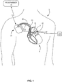
- FIG. 1 illustrates, diagrammatically, a patient 2 with implanted medical devices including a sensor assembly 10 implanted, for example, in the patient's pulmonary artery 6 through which blood flows from the heart 4 to the lungs, and another medical device 16, such as a pacemaker, defibrillator or the like.
- a sensor assembly 10 implanted, for example, in the patient's pulmonary artery 6 through which blood flows from the heart 4 to the lungs
- another medical device 16 such as a pacemaker, defibrillator or the like.
- the device 16 may have one or more leads 18, 20, 22 that are placed in electrical contact with selected portions of the cardiac anatomy in order to perform the functions of the device 16 as are well known to one skilled in the art.
- the device 16 also may have wireless capability to receive and transmit, by telemetry, signals relating to operation of the device.
- the device 16 may communicate wirelessly to an external device such as a programmer 14 or to another implanted device such as a sensor 12 of the sensor assembly 10.
- sensor assembly 10 is shown without a fixation assembly in FIG. 1 .
- the sensor 12 may communicate wirelessly with the programmer 14 or an external receiver 24 to provide in vivo data for selected physiological parameters to an external site to inform clinicians of the patient's status.
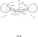
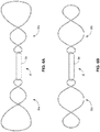
- FIGS. 2A , 2B , 3A, 3B , 4A , 4B , 5 , 6A, and 6B illustrate examples of sensor assemblies 10 adapted for minimally invasive placement in a patient's blood vessel.
- the sensor assemblies 10 are depicted in examples of deployment configuration (e.g., rather than being depicted in examples of pre-deployment configuration when sensor assemblies 10 may be in a sheath).
- FIGS. 2A-2B side profile views of the alternative examples of sensor assembly 10a and sensor assembly 10b (collectively "sensor assembly 10") are depicted.
- the sensor assembly 10 includes a sensor 12 coupled to fixation members 30a, 30b (collectively "fixation assembly 30").
- the fixation assembly 30 and sensor 12 are configured to enable the sensor assembly 10 to be provided in a delivery arrangement that enables the sensor assembly 10 to be navigated to an implant location from which the sensor assembly 10 can be deployed into the deployment configuration.
- the delivery configuration of the sensor assembly 10 defines a pitch, width, or diameter that is narrower, in relation to the deployment configuration of the sensor assembly 10 along a common plane.
- delivery configuration may be defined as the general shape of the sensor assembly 10 while being delivered to the blood vessel in a sheath, specifically as the shape relates to the fixation members 30a, 30b.
- deployment configuration may be defined as the general shape of the sensor assembly 10 while being delivered to the blood vessel in a sheath, once again specifically as the shape relates to the fixation members 30a, 30b.
- pitch refers to the height that a given loop of the fixation assembly 30 is configured to have in the deployment configuration, as depicted at least in FIGS.
- pitch refers to the distance that exists between the opposing wire portions within a given loop in a single plane, wherein the plane is perpendicular to the longitudinal axis 26 of the particular sensor assembly 10.
- pitch refers to the length of a line through the central longitudinal axis of a loop, with the line touching two points on opposing edges of each loop, where the central longitudinal axis of the loop may be parallel to the longitudinal axis 26 of the sensor assembly 10.
- the fixation assembly 30 Upon release/deployment, the fixation assembly 30 expands into the deployment configuration so as to be in physical contact with the wall of the blood vessel to maintain the positional integrity of sensor 12. In one example, the fixation assembly 30 will engage the interior wall of the vessel defining the blood flow lumen.
- the sensor 12 may be attached to the fixation assembly 30 in a manner such that the sensing element 32 of the sensor 12 is spaced from the wall of the vascular lumen to minimize adverse obstruction to blood flow through the lumen and to position the sensing element 32 of the sensor 12 to be fully exposed to the blood in the vessel, without obstruction from the housing of the sensor or the vessel wall.
- a bottom longitudinal wall LW2 of the capsule 34 of the sensor assembly 10a may be sintered to promote tissue growth along the bottom longitudinal wall LW2.
- the bottom longitudinal wall LW2 may be sintered as part of a manufacturing step (e.g., the bottom longitudinal wall LW2 may be sintered prior to being assembled within the capsule 34).
- a bottom portion 48 of the sealed housing that includes the bottom longitudinal wall LW2 may be sintered. Sintering the bottom longitudinal wall LW2 of the capsule may reduce strain on the fixation members 30a, 30b (e.g., as a result of the sintering providing some fixation force, the fixation members 30a, 30b may have to provide relatively less fixation forces).
- FIG. 3A illustrates a bottom perspective view of the sensor assembly 10a
- FIG. 3B illustrates a side cross-sectional view of the sensor assembly 10a.
- the features described with respect to sensor assembly 10a and FIGS. 3A and 3B may be included in sensor assembly 10b.
- the sensor 12 includes a capsule 34 that forms a sealed housing that encloses the operational components such as the electronic circuitry of the sensor assembly 10.
- the sealed housing is hermetically sealed.
- the capsule 34 defines longitudinal walls e.g., LW1, LW2, that extend from a first lateral side wall SW1 to a second lateral sidewall SW2.
- the longitudinal walls define the longitudinal axis of the sensor 12.
- the fixation members 30a, 30b may be coupled to an exterior of the capsule 34 such as the first and second sidewalls, respectively.
- the fixation members 30a, 30b may be configured to engage with a vascular wall along a plurality of planes 44a-d (collectively "planes 44").
- the fixation members 30a, 30b may expand to occupy the plurality of planes 44 in the deployment configuration after being released from a sheath as described herein.
- the fixation members 30a, 30b may therein have numerous planes of support upon deployment in the blood vessel, which may result in the sensor assembly 10 being more resistant to "twisting" in a direction generally perpendicular to one of the planes 44 (e.g., more resistant in comparison to an example sensor assembly 10 with a respective fixation assembly 10 that exists along a single plane).
- Fixation assembly 30 may apply little more than the force that is appropriate to hold the sensor assembly 10 in place without applying excessive force to that surface.
- the fixation assembly 30 may be constructed to apply light, but sufficient, force to the vessel. Such forces are at least less than those associated with the placement of vascular stents in which the objective may be to press against the vascular wall with sufficient force to provide scaffolding support for the vessel wall.
- FIGS. 4A and 4B are exploded perspective views of the sensor 12 in accordance with some examples.
- the capsule 34 may include an elongate body that defines an interior cavity.
- the interior cavity of the capsule 34 may be sized and shaped to contain the battery 40 and electronics and sensor components 42 of the sensor 12.
- the capsule 34 may be designed with shapes that are easily accepted by the patient's body while minimizing patient discomfort.
- the body of capsule 34 may be formed in a cylindrical shape with cylindrical sidewalls.
- Other non-cylindrical configurations may be employed, however, in which case the corners and edges may be designed with relatively large radii to present a capsule having smoothly contoured surfaces.
- the body of capsule 34 may be formed as a generally rectangular structure, which means that the outline of the shape of capsule 34 resembles a rectangle as defined by two lateral side walls SW1, SW2 and two longitudinal side walls LS1, LS2, with contoured edges and corners.
- the capsule 34 may be formed having two sections 36, 38.
- one section contains and/or supports the sensing element 32 while the other section contains and/or supports components operably connected to the sensing element.
- section 36 may contain and/or support a pressure sensing diaphragm of sensor 12 and sensor components 42 while section 38 contains the battery 40.
- the fixation members 30a, 30b have opposing arrangements as reflected over a central plane 54 of the sensor 12.
- the fixation members 30a, 30b having opposing arrangements as reflected over the central plane 54 may include specific features of the fixation members 30a, 30b (e.g., a relative rise or dip of a wire along the longitudinal axis 26 of a respective fixation member) being substantially opposite on a relative side of the sensor 12.
- fixation assemblies 30 may include near portions of wire 56a-b (collectively “near portions of wire 56”) that extend axially out from the capsule 34 closer to a first longitudinal side wall LS1 (e.g., closer to the depicted vantage point) than far portions of wire 58a-b (collectively “far portions of wire 58").
- a near portion of wire 56 of a respective fixation member 30 indicates the portion of wire of said fixation member 30 that is in front of a respective far portion of wire 58 of the fixation member 30 as depicted at a juncture 52 (e.g., where a near portion of wire 56 obscures the far portion of wire 58 at the juncture 52).
- a near portion of wire 56 obscures the far portion of wire 58 at the juncture 52.
- fixation members 30a, 30b having opposing arrangements as reflected over a central plane of the sensor 12 may result in load balancing benefits (e.g., as the two fixation members 30a, 30b are configured to stabilize in different directions against different rotations), which may result in a sensor assembly 10 being more stably deposited into a blood vessel.
- the capsule 34 may be formed from one or more biocompatible materials that can be sealed (e.g., hermetically sealed) when the sections 36, 38 are joined.
- biocompatible materials may be employed, as will be understood by skilled in with the art, including metals and biocompatible plastics.
- the sections 36, 38 may be formed from unalloyed titanium with an American Society for Testing and Materials (ASTM) grade between 1 and grade 4, or the sections may be formed from an alloyed titanium (e.g., grade 5) that includes aluminum and vanadium.
- section 36 may be formed from a biocompatible mineral, such as sapphire or another variety of corundum.
- the metal material of the capsule 34 may optionally be selected to be compatible with the fixation assembly 30 material so as to permit the fixation assembly 30 being securely coupled to the capsule 34.
- the capsule 34 along with the fixation assembly 30 may be integrally formed from one or more of the same or distinct materials.
- the capsule 34, as well as some portions of the fixation member 30, may be encapsulated in a biologically inert dielectric barrier material such as a film of silicone or polyp-xylylene) polymer sold under the trademark PARYLENE
- capsule 34 may include fasteners F1, F2 that define channels for reception of a segment of the fixation assembly 30.
- capsule 34 may include fasteners F3, F4 that define channels for reception of a segment of the fixation assembly 30.
- the received segment may include a portion along a length of the fixation assembly 30 or a free end of the fixation assembly 30.
- the fasteners F1-F4 may be coupled to an exterior of the capsule 34, or in alternative examples, formed integrally with the capsule 34.
- the fasteners F1, F2 are provided at an exterior of the capsule 34 at the lateral sidewalls SW1, SW2, respectively.
- FIG. 4A the fasteners F1, F2 are provided at an exterior of the capsule 34 at the lateral sidewalls SW1, SW2, respectively.
- the fasteners F3, F4 are provided at spaced apart locations on an exterior of one or more of the longitudinal walls of the capsule 34, such as on the top longitudinal wall LW1, as depicted in FIG. 4B , or alternatively on the bottom longitudinal wall LW2.
- Spaced apart locations may include four locations on a longitudinal wall LW1, LW2 of the capsule 34, where a first two spaced apart locations are a first distance away from each other on a first lateral sidewall SW1, and the second two spaced locations are mirrored across the central plane 54 of the sensor assembly 10 the first distance away from each other on the second lateral sidewall SW2.
- the fasteners F1-F4 are formed as pairs of tabs that are arranged to define one or more channel(s) for receiving one or more segment(s) of the fixation assembly 30.
- Each fastener F1-F4 can include a pair of tabs that are aligned longitudinally as described, for example, in U.S. patent 8,864,676 to Beasley et al.
- the fasteners F1-F4 may be coupled to the capsule 34 through welding, for example.
- the fasteners F1-F4 may be formed integrally with the capsule 34.
- the fasteners F1-F4 may be on opposing ends of the capsule 34. It is to be understood that the description of the fasteners F1-F4 is not intended to be limiting, and rather, it is provided to explain the context of aspects of the disclosure.
- the fasteners F1-F4 are formed as tubular structures that define channels that are sized to receive a segment of each of the fixation members 30a, 30b.
- the fasteners F1-F4 may be formed as discrete components, such as tubes, for example, that can be coupled to the capsule 34 through coupling techniques such as welding or bonding agent such as glue or crimping.
- the fasteners F1-F4 may be formed integrally with the capsule 34.
- the fixation assembly 30 may be coupled to the fasteners F1-F4 by any suitable coupling technique such as welding, crimping, bonding agent such as glue, or frictional fit.
- the channels of fasteners F1-F4 may optionally be defined to receive a segment of the fixation members 30a, 30b in a snug fit arrangement to prevent relative movement between the capsule 34 and the fixation assembly 30.
- the thickness of a cross section of fixation assembly 30 may be on the order of 0.1524 mm (0.006 inch) for a round shape or 0.13462 mm by 0.3048 mm (0.0053 inch by 0.012 inch) for a rectangular shape.
- the diameter (or width) of the channel of each of the fasteners may be on the order of 0.254 mm to 0.635 mm (0.010 inch to 0.025 inch).
- free ends 68a-d (collectively, “free ends 68") of a fixation member 30a, 30b may be the two terminating points of the wire of a respective fixation member 30, 30b which may therein each be connected to the capsule 34.
- the free ends 68 of each of the fixation members 30a, 30b may be oriented in opposing directions.
- a first free end 68a, 68c may be oriented downward in relation to the lateral sidewall SW1, SW2, while the other ends 68b, 68d may be oriented upward in relation to the lateral sidewalls SW1, SW2 as shown in FIG. 4A .
- such an orientation can provide a degree ofload cancellation that minimizes load transfer to the sensing element 32.
- one of the fixation members e.g., 30a may be coupled along a lateral sidewall such as SW1 as shown in FIG. 4A
- the other of the fixation members e.g., 30b may be coupled to a longitudinal wall such as LW1 or LW2 as shown in FIG. 4B .
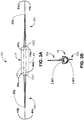
- FIG. 5 depicts the fixation assembly 30 of the sensor assembly 10.
- the fixation members 30a, 30b comprises a flexible material and may be configured in a helical configuration in one examples.
- Each of the fixation members 30a, 30b may be coupled at opposing ends of the sensor capsule 34.
- the fixation members 30a, 30b are coupled at opposing lateral sidewalls of capsule 34 (e.g., as depicted with respect to 1Oa and 2a)
- the fixation assembly 30 may be formed from a highly elastic material capable of "remembering" a first shape, such that even when the fixation assembly 30 is condensed to a second, smaller shape (e.g., when the fixation assembly 30 is inside a sheath) the fixation assembly 30 may return to the first shape when no longer so condensed (e.g., when removed from the sheath).
- the fixation assembly 30 may be formed from a highly elastic biocompatible alloy capable of forming stress induced martensite (SIM).
- Nitinol (TiNi) is an example of such materials that are also referred to as being “pseudoelastic” or “superelastic.”
- Each of the fixation members 30a, 30b can be formed into a single, integral component.
- the fixation members 30a, 30b may be formed from a wire-like element that is configured into the desired shape. Such wire-like elements may comprise a linear element having any desired cross-section such as round or rectangular.
- the fixation members 30a, 30b may be formed from a sheet of material by laser cutting or electrochemical etching or other fabricating techniques known in the art. Regardless of the construction method, each of the resulting fixation members 30a, 30b may have a substantially uniform thickness. As used in this disclosure, the term substantially uniform thickness means that the thickness dimension along a length of the members 30a, 30b is constant or is within a variation of up to 15%.
- Each one of the fixation members 30a, 30b may be configured to define a pair of longitudinally spaced asymmetric loops 50a, 50b formed in a helical configuration when attached to capsule 34.
- the asymmetric loops 50a, 50b are formed in an end-to-end configuration so as to intersect or overlap at junctions 52. It should be understood that the asymmetric loops 50a, 50b need not be in contact at the junctions 52 (e.g., as a result of being in different planes 44 to have numerous planes 44 of support as discussed herein), but rather, that they may overlap as viewed from the side to form a helical configuration as shown in the perspective view of FIG. 3 .
- each of the fixation members 30a, 30b may generally resemble the number "8" in some examples when viewed from a side profile.
- the fixation members 30, 30b may include multi-loop structures including three or more loops as depicted, for example, in FIGS. 6A, 6B .
- a length of the fixation members 30a, 30b may be contiguous. Alternatively, a length of the fixation members may be detached around a perimeter of one of the loops away from the junction. It should be understood that either one or both fixation members 30a, 30b may be contiguous or detached around the perimeter.
- a fixation member 30a, 30b that is detached may include two discrete portions of wire that are each individually coupled to the capsule 34 in a manner consistent with this disclosure.
- a fixation member 30a, 30b that is detached may maintain substantially similar shapes as other fixation members 30a, 30b discussed herein.
- Fixation members 30a, 30b that are detached may have "breaks" 35a-35b (collectively “breaks 35") at a location furthest away from the capsule 34 along the longitudinal axis 26 as depicted in FIG. 3A .
- a far portion of wire 56a may not be part of the same wire as near portion of wire 56b, but instead the far portion of wire 56a and near portion of wire 56b may be two discrete portions of wire that terminate at substantially the same spot (e.g., at the break 35) along a fixation member 30a, 30b.
- the two discrete portions of wire may terminate at the break 35 such that a fixation member 30a, 30b that is detached may appear to be a single piece of wire (e.g., it may appear to be contiguous) before a relatively large force is applied upon the respective fixation member 30a, 30b and causes the discrete portions of a fixation member 30a, 30b that is detached to separate at the break 35.
- a fixation member 30a, 30b that is detached may encounter relatively less strain upon the discrete wire portions as a result of being detached.
- the asymmetric loop 50a may be formed having a maximum pitch PI that is of a lesser magnitude than a maximum pitch P2 of the asymmetric loop 50b.
- a maximum pitch of a loop is the pitch of the largest magnitude of the respective loop.
- the pitch of loop 50a decreases in a direction towards the junction 52 along a longitudinal axis 26 of the sensor assembly 10a (or increases in a direction away from the junction 52).
- the pitch of loop 50b decreases in a direction towards the junction 52 along a longitudinal axis 26 of the sensor assembly 10 (or increases in a direction away from the junction 52).
- each of the additional loops may likewise be formed with decreasing pitches, relative to a junction 52 of such additional loop(s) to one of the adjoining loop(s).
- the maximum pitches PI, P2 may be configured to improve a fit of the fixation members 30a, 30b in the blood vessel.
- P2 being larger than PI, may be configured to be slightly greater (e.g., 10% more) than the height of the respective blood vessel that the sensor 10 assembly may be implanted in, such that the fixation members 30a, 30b engage with but do not pierce/push through the walls of the blood vessel.
- the radius of the wires of the fixation members 30a, 30b may be as large as possible (e.g., while maintaining shape memory and proper alignment) to minimize loading on the capsule 34 and therein the sensor 12.
- the fixation members 30a, 30b are each coupled to the capsule 34 at a segment of the first loop 50a. As such, the fixation members 30a, 30b may be coupled to the capsule 34 such that the pitch of the first loop 50a decreases along a longitudinal axis 26 of the housing towards the junction 52. In some examples, the pitch of the first loop 50a increases for a relatively short distance 46a-b (collectively “distances 46") along the longitudinal axis before the pitch decreases. Conversely, the pitch of the second loop increases along the longitudinal axis 26 away from the junction 52.
- fixation members 30a, 30b may be compressible along a dimension defining the pitch of the first loop 50a and second loop 50b such that each member is collapsible to a reduced pitch in a delivery configuration and expanded to an magnified pitch in a deployment configuration.
- some or all of the wire of the fixation assembly may be coated (e.g., coated for insulation purposes) or otherwise covered with paralyne or another insulating material.
- wires of the fixation members 30a, 30b may be exposed (e.g., without an electrical insulator around all or part of the conductor of a wire) to create electrical contact with tissue of the patient 2.
- the fixation members 30a, 30b may be configured to make electrical contact with tissue of the patient 2 in order to transmit signals through the tissue of a patient 2 (e.g., signals to a medical device 16 or a programmer 14 or an external receiver 24).
- wires may be stripped after the maximum pitch PI of the first loops 50a.
- all of the wire of the fixation members 30a, 30b may be stripped with the exception of the wire within the distances 46 of the capsule 34. In such cases, stripping the wires after the maximum pitch PI of the first loops 50a may provide transmission strength benefits to the sensor assembly 10.
- the fixation assembly 30 may stably position the sensor 12 to achieve stable and durable sensing parameters. Further, the fixation assembly 30 may reduce the loads that are transferred by the fixation assembly 30 to the sensing element 32.
- the sensing element 32 is a deformable pressure membrane. Reducing the loads that are transferred to the sensing element may be achieved by providing a fixation assembly 30 having a multi-loop configuration such that at least one of the loops provides strain relief for coupling to the capsule 34 while a second of the loops provides the fixation to maintain the positional integrity of the sensor 12 at the desired implant location.
- the fixation assembly 30 can be constructed such that an outer perimeter of each of the fixation members 30a, 30b is aligned with a plane defined by an exterior portion of the capsule 34. Such a plane can be defined by the bottom longitudinal section of capsule 34 as shown in FIG. 5 .
- an arrangement enables the bottom of the capsule 34 to be in contact or adjacent to the wall of the vessel during use while positioning the sensor in the blood flow path within the vessel.
- Such a construction also provides for unobstructed passage of a guidewire within the lumen of the delivery tool during the implantation of the sensor assembly 10.
- the fixation members 30a, 30b are coupled at two separate locations on opposing ends of the capsule 34. This provides transverse stability of the capsule 34.
- coupling the fixation members 30a, 30b to the two opposing ends of capsule 34 may provide a fixation structure with a decreasing pitch in opposing directions, which further minimizes the load transfer to the sensing element 32.
- the direction of the coupling of fixation assembly 30 is depicted as being parallel with the longitudinal axis of the capsule 34, it should be understood that alternative examples may selectively couple the fixation assembly 30 in a different orientation relative to the capsule 34.
- the fixation assembly 30 may be coupled perpendicular to the longitudinal axis 26 of the capsule 34.
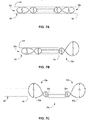
- FIGS. 7A-7C depict, diagrammatically and in fragmented illustration, the sensor assembly in conjunction with an example delivery system that may be used to deliver and deploy the sensor assembly in a desired implant location.
- the fixation members 30a, 30b are formed from a flexible material that enables the fixation assembly 30 to be compressed to a narrower shape having a smaller effective cross section in which it may be mounted to and delivered by a delivery catheter 60 to an intended implant location such as the pulmonary artery.
- the larger of the loops 50 of each of the fixation members 30a, 30b is compressed from its relaxed, expanded deployment configuration to a narrower, more elongated delivery configuration defined by loop segments that are drawn more closely parallel to each other.
- forming fixation members 30a, 30b from a superelastic material e.g., such as superelastic nitinol, which has the ability to undergo extreme strain without permanent deformation
- other materials such as stainless steel or plastic may suitably be used to form the fixation members 30a, 30b.
- each of loops 50 of the fixation members 30a, 30b may be compressed from a relaxed, expanded shape to a narrower, more elongated shape.
- FIGS. 7A-7B the fixation assembly 30 is shown with the fixation members 30a, 30b in a compressed, delivery configuration profile as may be the case while disposed within the delivery catheter 60.
- the delivery configuration enables the sensor assembly 10 to be delivered to a desired implant location through a delivery catheter 60.
- FIG. 7A shows the fixation assembly 30 in a delivery configuration such that at least the dimension along the maximum pitch P2 of the second loop 50b is reduced to define a low profile of fixation members 30a, 30b.
- the fixation assembly 30 may be compressed such that the dimensions of both the maximum pitch PI of the first loop 50a and the maximum pitch P2 of the second loop 50b are reduced to define a low profile of fixation members 30a, 30b.
- FIG. 7B the fixation assembly 30 is shown partially retracted from the delivery catheter 60 such that the fixation member 30b is in the expanded, deployment configuration such that the dimension along the maximum pitch PI of the first loop 50a and/or the maximum pitch P2 of the second loop 50b is expanded to its deployed configuration.
- the delivery catheter 60 may be in the form of an elongate tubular shaft 62 having proximal end 64 and distal end 66 with the sensor assembly 10 disposed within a region of the shaft.
- the shaft 62 may be formed from a material and dimensioned to have sufficient flexibility to be navigated through the patient's vasculature to the intended implant location.
- the delivery catheter 60 may further include a guide sheath or used in association with a guide wire, as is known to one skilled in the art.
- the sensor assembly 10 may be releasably retained at the region of the shaft by any suitable arrangement, such as the rotatable helical retention elements described in U.S. Patent 8,864,676 .
- the delivery catheter 60 may be advanced through a guide sheath that, when retracted, exposes the sensor assembly 10 at a desired implant location. In alternative examples, the delivery catheter 60 may be advanced through an introducer to the desired implant location. Once the distal end 66 is positioned near the implant location, the sensor assembly 10 may be deployed by advancing the distal end 66 to deploy the sensor assembly 10. As the sensor assembly 10 is released it self-expands to its expanded configuration within the target implant location.
- the entire sensor assembly 10 is shown in an expanded deployment configuration profile, which typically occurs following release of the fixation members 30a, 30b from the delivery catheter 60.
- the sensor assembly 10 is typically advanced from the delivery catheter 60 and the expansion of the loop 50b causes the sensor assembly 10 to be securely positioned at the target implant location. Repositioning may be accomplished by advancing the delivery catheter 60 to recapture the fixation members 30a, 30b. The recaptured sensor assembly 10 may then be repositioned and redeployed.
- the delivery catheter 60 may be advanced to the target implant location by advancing it through a guide sheath, an introducer, a guide wire in an over-the-wire system, or any other mechanism which is known to those skilled in the art. It should be understood that delivery catheter 60 is only one example of a delivery system for sensor assembly 10. Other types of delivery systems can be utilized, including, for example, mechanisms that are slidably disposed around the sensor assembly 10 to constrain the sensor assembly in its delivery configuration until a pusher mechanism ejects the sensor assembly 10 from the distal end of the catheter. It should be noted that the superelastic construction of the fixation members 30a, 30b enables the fixation members 30a, 30b to be elastically distorted from respective planar expanded shape to a shape adapted to fit onto or within a delivery catheter.
- FIG. 8 illustrates, diagrammatically, the positioning of the sensor assembly 10 in a target implant location.
- the implant location is a human pulmonary artery 6, which is generally relatively short and often has a lumen that tapers in the direction of blood flow. The degree of taper may vary from patient to patient, with patients suffering from chronic heart failure tending to have more severe taper with higher pulmonary blood pressures.
- the main pulmonary artery branches into left and right pulmonary arteries 8, 9. Whether the clinician will elect to place a device in the main artery or one of the branches of the pulmonary artery tree will depend on the anatomy and condition of the particular patient among other factors.
- the delivery catheter 60 When deploying the sensor assembly 10, the delivery catheter 60 may be positioned so that the more distal of fixation members 30a, 30b will be located in the selected portion of the selected artery.
- Fixation assembly 30 may apply little more than the force that is required to hold the sensor assembly 10 in place without applying excessive force to that surface.
- the fixation assembly 30 is constructed to apply light, but sufficient, force to the vessel. Such forces are at least less than those associated with the placement of vascular stents in which the objective is to press against the vascular wall with sufficient force to provide scaffolding support for the vessel wall.
- aspects of the disclosure intend to maintain the sensor assembly 10 in the vessel, without migrating upstream or downstream, while supporting the sensor 12 in its intended position and orientation for measurement of stable and durable sensing parameters.
- the fixation members 30a, 30b When the sensor assembly 10 is deployed, the fixation members 30a, 30b expand along a single plane with at least one loop of each fixation member 30a and 30b expanding to a dimension to be in contact with the luminal wall of the vessel. Regardless of the orientation of the sensor assembly 10 during delivery, the at least one loop that is in contact with the vessel wall will seat itself at substantially diametrically opposite surfaces of the vessel wall (e.g., at least one loop of each fixation member 30a, 30b may press into both sides of a vessel wall). As used in this disclosure, the term substantially diametrically opposite may mean that the surfaces are opposite one another or within a 15% variance of being opposite each other.
- such a construction can enable the at least one loop to maintain the positional integrity of the sensor assembly 10 with respect to the vessel.
- the sensing element 32 may be oriented along a longitudinal axis in relation to the length of the vessel lumen to be exposed fully and without obstruction to blood flow in the lumen.
- fixation assembly and sensor are arranged such that the sensing element faces generally parallel to the plane of the fixation assembly.
- the fixation assembly also may be configured to position the sensor housing and, particularly, the sensing element, away from the vessel wall to lessen the risk of turbulent flow through the vessel.
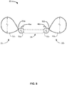
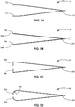
- FIGS. 9A-D illustrate top views of example fixation members 70, 76, 82, 88 for an example sensor assembly (not depicted).
- FIGS. 9A-D depicts fixation members 70, 76, 82, 88 from the same view as FIG. 3A .
- Fixation members 70, 76, 82, 88 includes an angled portion 74, 80, 86, 92 (respectively) and free ends for connecting the respective fixation members 70, 76, 82, 88 to respective capsules 34.
- the specific angles of the fixation members 70, 76, 82, 88 are depicted for purposes of illustration only, other angles and configurations are also possible.
- fixation members 70, 76, 82, 88 could have a more acute angle similar to the angle depicted in FIG. 3A .
- the fixation members 70, 76, 82, 88 may have two loops, three loops, or more than three loops.
- Fixation member 70 includes an angled portion 74 and free ends 72a-b (collectively "free ends 72").
- the free ends 72 may be parallel with an axis 26 of the sensor assembly 10.
- the amount of the fixation assembly 70 that is comprised of the free ends 72 is for example purposes only; in other examples, the free ends 72 may comprise a smaller or larger overall amount of the fixation member 70.
- the free ends 72 may connect to the capsule 34 as described herein. In some examples, it may be easier to attach the fixation member 70 to the capsule 34 due to the free ends 72 lining up with relative components (e.g., fasteners) of the capsule 34.
- Fixation member 76 includes an angled portion 80 and two free ends 78a-b (collectively “free ends 78").
- the free ends 78 may be parallel with planes 84a-b (collectively “planes 84") of the fixation member 76.
- Planes 84 of the fixation member 76 may be substantially similar to planes 44 of the fixation members 30a, 30b as described herein.
- the free ends 78 may connect to a capsule 34 as described herein.
- fixation member 76 may experience benefits in balancing loads throughout the fixation assembly 76 being as there are no turns in transitioning to the free ends 78 (as seen from the top) in which loads may be concentrated. Further, in certain examples, it may be easier/less expensive to manufacture fixation member 76 than other fixation members, as less turns are required.
- Fixation member 82 includes an angled portion 88 and free ends 86a-b (collectively "free ends 86").
- the length of the free ends 86 is for example purposes only; in other examples, the free ends 86 may be longer or shorter.
- the free ends 86 may connect to the capsule 34 as described herein.
- the free ends 86 may parallel to a respective lateral sidewall SW1, SW2 of the capsule 34.
- loads upon the angled portion 88 may be relatively lower, as loads do not transfer efficiently from the free ends 86 to the angled portion 88 due to the free ends being parallel with a respective lateral wall SW1, SW2.
- Fixation member 90 includes an angled portion 94 and free ends 92a-b (collectively "free ends 92").
- the length and angle of the free ends 92 is for example purposes only; in other examples, the free ends 92 may be longer or shorter at different angles.
- the free ends 92 may connect to the capsule 34 as described herein.
- the free ends 92 may curve into the capsule with a radius 96. In some examples, loads upon the angled portion 94 may be relatively lower, as loads do not transfer efficiently from the free ends 92 to the angled portion 94 due to the curve with the radius 96.
- FIG. 10 illustrates a side profile view of an example fixation member 100 for an example sensor assembly (not depicted). All dimensions are in millimeters and are for purposes of example only; other dimensions consistent with this disclosure are also possible.
- a connection portion 102 of the fixation member 100 may incorporate any of the connection configurations discussed in FIGS. 9A-9D .
- FIG. 11 illustrates a side profile view of example configurations of a fixation member 110 for an example sensor assembly (not fully depicted).
- Fixation member 110 may attach to a capsule 34 as depicted. In other examples, fixation member attaches to a capsule 34 in other manners consistent with this disclosure (e.g., as depicted in FIG. 4A ).
- Fixation member 110 has a first loop 124 and a second loop 126. In other examples, fixation member 110 has more than two loops as described above.
- a first loop 124 of the fixation member 110 may be configured with any one of a plurality of maximum pitches 120a-d (collectively "maximum pitches 120").
- the first loop 124 may be configured with to have one of a plurality of maximum pitches 120 as a result of altering arrangements of far portions of wire 58 that is closer to longitudinal side wall LS2 than longitudinal side wall LS1.
- the far portion of wire 58 may be arranged differently immediately upon extending axially out from the capsule 34.
- the far portion of wire 58 may be arranged in the arrangements 112, 114, 116, 118 depicted in FIG. 11 .
- the fixation member 110 may be arranged in other manners that are consistent with this disclosure (e.g., the far portion of wire 58 may arranged to occupy space between arrangement 114 and arrangement 118).
- an arrangement 112 of the far portion of wire 58 may include the far portion of wire 58 rising up (e.g., moving axially out from the capsule 34 in the general direction of the longitudinal wall LW1 relative to the capsule 34) such that the pitch of the first loop 124 increases relatively quickly to a maximum pitch 120a and then decreases to the juncture 52.
- an arrangement 116 of the far portion of wire 58 may include the far portion of wire 58 rising up relatively moderately such that the pitch of the first loop 124 increases to a to a maximum pitch 120b (e.g., where maximum pitch 120b is less than maximum pitch 120a) and then decreases to the juncture 52.
- an arrangement 118 of the far portion of wire 58 may include the far portion of wire 58 dipping down (e.g., moving axially in the general direction of the longitudinal wall LW2 relative to the capsule 34) before rising slightly to the maximum pitch 120c (e.g., where maximum pitch 120c is less than maximum pitch 120b), such that the pitch of the first loop 124 slightly increases until the maximum pitch 120c and then slightly decreases until the juncture.
- an arrangement 114 of the far portion of wire 58 may dip down at a slower rate than the near portion of wire 56 dips down, such that the first loop 124 has a maximum pitch of 120d (e.g., where the maximum pitch 120d is less than the maximum pitch 120c).
- a larger maximum pitch 120 of the first loop 124 may provide more stiffness to the fixation assembly 124.
- arrangement 112 may be relatively more stiff than arrangement 116 (e.g., as maximum pitch 120a is larger than maximum pitch 120b), while arrangement 116 is relatively more stiff than arrangement 118, while arrangement 114 is relatively more stiff than arrangement 118.
- different arrangements 112, 114, 116, 118 may be utilized for different applications depending upon the stiffness required for the specific parameters of the respective application.
- an implantable medical device comprises:
Claims (14)
- Dispositif médical implantable, comprenant :un boîtier (34) comportant une source d'alimentation, un élément de détection (32) et un circuit électronique (42) configuré pour générer un signal indiquant un paramètre physiologique mesuré par l'élément de détection, le boîtier ayant des première et seconde extrémités opposées ; etun ensemble de fixation (30) comportant des éléments de fixation asymétriques (30a, 30b) couplés aux extrémités opposées du boîtier, dans lequel chacun des éléments de fixation asymétriques comporte une structure avec une pluralité de boucles (50), dans lequel une première boucle de la pluralité de boucles a un pas maximal qui est différent d'un pas maximal d'une seconde boucle de la pluralité de boucles, dans lequel chacun des éléments de fixation asymétriques est configuré selon une structure en huit avec chacune des boucles de la structure en huit ayant un pas maximal différent.
- Dispositif médical implantable selon la revendication 1, dans lequel chaque boucle de la structure est formée dans une configuration hélicoïdale.
- Dispositif médical implantable selon l'une quelconque des revendications 1 et 2, dans lequel la première boucle (50a) est couplée au boîtier de sorte qu'un pas de la première boucle augmente de la jonction vers le boîtier et qu'un pas de la seconde boucle (50b) augmente dans une direction opposée à la jonction.
- Dispositif médical implantable selon l'une quelconque des revendications 1 à 3, dans lequel chacun des éléments de fixation asymétriques est configuré pour entrer en contact avec les parois d'un vaisseau sanguin le long d'une pluralité de plans.
- Dispositif médical implantable selon la revendication 4, dans lequel chaque plan de la pluralité de plans est perpendiculaire à une surface de la capsule sur laquelle les éléments de fixation sont fixés.
- Dispositif médical implantable selon l'une quelconque des revendications 1 à 5, dans lequel chacun des éléments de fixation comporte des première et seconde extrémités libres (78a, b), dans lequel les première et seconde extrémités libres sont parallèles à un plan de la pluralité de plans ; ou dans lequel chacun des éléments de fixation comporte des première et seconde extrémités libres, les premières extrémités libres des éléments de fixation étant orientées dans des directions opposées les unes par rapport aux autres et les secondes extrémités libres des éléments de fixation étant orientées dans des directions opposées les unes par rapport aux autres ; ou dans lequel chacun des éléments de fixation comporte des première et seconde extrémités libres, dans lequel les première et seconde extrémités libres sont parallèles à un axe longitudinal du dispositif médical implantable ; ou dans lequel chacun des éléments de fixation comporte des première et seconde extrémités libres, dans lequel les première et seconde extrémités libres sont perpendiculaires à un axe longitudinal du dispositif médical implantable.
- Dispositif médical implantable selon l'une quelconque des revendications 1 à 6, dans lequel les éléments de fixation asymétriques ont des agencements opposés tels qu'ils sont définis sur un plan central du dispositif médical implantable.
- Dispositif médical implantable selon l'une quelconque des revendications 1 à 7, dans lequel au moins une boucle de la structure est dimensionnée avec un diamètre pour entrer en contact avec une partie d'une paroi d'un vaisseau afin de maintenir ainsi le capteur de pression au niveau d'un emplacement fixe à l'intérieur du vaisseau.
- Dispositif médical implantable selon la revendication 8, dans lequel le vaisseau est une artère pulmonaire.
- Dispositif médical implantable selon l'une quelconque des revendications 1 à 9, dans lequel un pas de chaque boucle augmente à partir de la jonction le long d'un axe qui est parallèle à un axe longitudinal du boîtier.
- Dispositif médical implantable selon l'une quelconque des revendications 1 à 10, dans lequel l'élément de détection est une membrane de pression et le paramètre physiologique mesuré est la pression sanguine.
- Dispositif médical implantable selon l'une quelconque des revendications 1 à 11, dans lequel la structure a un pas variable de sorte que l'ensemble de fixation est compressible dans une configuration de pose et extensible dans une configuration de déploiement différente de la configuration de pose.
- Dispositif médical implantable selon l'une quelconque des revendications 1 à 12, dans lequel une surface du boîtier qui est en contact avec une paroi d'un vaisseau sanguin est frittée.
- Système médical implantable, comprenant :
un dispositif médical implantable selon une quelconque revendication précédente, le dispositif médical implantable étant un capteur physiologique, le système comportant en outre un cathéter de pose (60) ayant un corps allongé pour la pose du capteur physiologique.
Applications Claiming Priority (2)
| Application Number | Priority Date | Filing Date | Title |
|---|---|---|---|
| US201562267000P | 2015-12-14 | 2015-12-14 | |
| PCT/US2016/066588 WO2017106300A2 (fr) | 2015-12-14 | 2016-12-14 | Capteur médical implantable et système de fixation |
Publications (2)
| Publication Number | Publication Date |
|---|---|
| EP3389776A2 EP3389776A2 (fr) | 2018-10-24 |
| EP3389776B1 true EP3389776B1 (fr) | 2019-11-27 |
Family
ID=58737846
Family Applications (1)
| Application Number | Title | Priority Date | Filing Date |
|---|---|---|---|
| EP16867375.4A Active EP3389776B1 (fr) | 2015-12-14 | 2016-12-14 | Capteur médical implantable et système de fixation |
Country Status (4)
| Country | Link |
|---|---|
| US (2) | US11154207B2 (fr) |
| EP (1) | EP3389776B1 (fr) |
| CN (1) | CN108601943B (fr) |
| WO (1) | WO2017106300A2 (fr) |
Families Citing this family (8)
| Publication number | Priority date | Publication date | Assignee | Title |
|---|---|---|---|---|
| US10638955B2 (en) | 2011-06-30 | 2020-05-05 | Endotronix, Inc. | Pressure sensing implant |
| US11896365B2 (en) | 2011-06-30 | 2024-02-13 | Endotronix, Inc. | MEMS device for an implant assembly |
| US10226218B2 (en) | 2011-06-30 | 2019-03-12 | Endotronix, Inc. | Pressure sensing implant |
| WO2018156930A1 (fr) | 2017-02-24 | 2018-08-30 | Endotronix, Inc. | Ensemble lecteur capteur sans fil |
| US11615257B2 (en) | 2017-02-24 | 2023-03-28 | Endotronix, Inc. | Method for communicating with implant devices |
| WO2018195430A1 (fr) * | 2017-04-20 | 2018-10-25 | Endotronix, Inc. | Système d'ancrage pour un dispositif délivré par un cathéter |
| EP3654835A1 (fr) | 2017-07-19 | 2020-05-27 | Endotronix, Inc. | Système de surveillance physiologique |
| CN117339108B (zh) * | 2023-12-04 | 2024-02-13 | 山东瑞安泰医疗技术有限公司 | 一种可降低起搏阈值的无导线心脏起搏器系统 |
Family Cites Families (33)
| Publication number | Priority date | Publication date | Assignee | Title |
|---|---|---|---|---|
| JPS62240025A (ja) * | 1986-04-10 | 1987-10-20 | 住友電気工業株式会社 | カテ−テル型センサ |
| US5103832A (en) | 1990-10-11 | 1992-04-14 | Gregmed | Biological pressure transducer zeroing and levelling reference apparatus |
| US5397342A (en) | 1993-06-07 | 1995-03-14 | Cardiac Pacemakers, Inc. | Resilient structurally coupled and electrically independent electrodes |
| US6579235B1 (en) | 1999-11-01 | 2003-06-17 | The Johns Hopkins University | Method for monitoring intraocular pressure using a passive intraocular pressure sensor and patient worn monitoring recorder |
| US20060287602A1 (en) | 2005-06-21 | 2006-12-21 | Cardiomems, Inc. | Implantable wireless sensor for in vivo pressure measurement |
| US20050154320A1 (en) | 2004-01-09 | 2005-07-14 | Froelich Michael A. | Methods and devices for accurate pressure monitoring |
| US7572228B2 (en) | 2004-01-13 | 2009-08-11 | Remon Medical Technologies Ltd | Devices for fixing a sensor in a lumen |
| US7792583B2 (en) | 2004-03-16 | 2010-09-07 | Medtronic, Inc. | Collecting posture information to evaluate therapy |
| WO2006012050A2 (fr) | 2004-06-30 | 2006-02-02 | Cvrx, Inc. | Structures de connexion pour un corps conducteur a electrodes extravasculaires |
| US7335161B2 (en) | 2004-08-20 | 2008-02-26 | Cardiac Pacemakers, Inc. | Techniques for blood pressure measurement by implantable device |
| US8118749B2 (en) * | 2005-03-03 | 2012-02-21 | Cardiomems, Inc. | Apparatus and method for sensor deployment and fixation |
| US7566034B2 (en) | 2005-08-31 | 2009-07-28 | Tapco International Corporation | Bi-directional mounting bracket assembly for exterior siding |
| US7566308B2 (en) | 2005-10-13 | 2009-07-28 | Cardiac Pacemakers, Inc. | Method and apparatus for pulmonary artery pressure signal isolation |
| US20070156057A1 (en) | 2005-12-30 | 2007-07-05 | Cho Yong K | Method and system for interpreting hemodynamic data incorporating patient posture information |
| EP1993438A1 (fr) | 2006-03-14 | 2008-11-26 | CardioMems, Inc. | Detecteur, systeme de distribution et procede de fixation |
| ES2369203T3 (es) * | 2006-09-15 | 2011-11-28 | Cardiac Pacemakers, Inc. | Anclaje para un dispositivo médico implantable. |
| MY165532A (en) * | 2007-02-01 | 2018-04-02 | Proteus Digital Health Inc | Ingestible event marker systems |
| US20080243016A1 (en) | 2007-03-28 | 2008-10-02 | Cardiac Pacemakers, Inc. | Pulmonary Artery Pressure Signals And Methods of Using |
| WO2009091965A1 (fr) * | 2008-01-18 | 2009-07-23 | Med Institute, Inc. | Système de fixation d'un dispositif intravasculaire ayant un corps extensible tubulaire |
| US20150151121A1 (en) * | 2008-01-31 | 2015-06-04 | Enopace Biomedical Ltd. | Enhancing perfusion by contraction |
| US20090248034A1 (en) * | 2008-03-28 | 2009-10-01 | Medtronic Vascular, Inc. | Method of Diagnosing and Treating Benign Prostatic Hyperplasia |
| US8777850B2 (en) | 2008-10-31 | 2014-07-15 | Medtronic, Inc. | Heart failure patient management using an implantable monitoring system |
| WO2011002564A1 (fr) | 2009-07-02 | 2011-01-06 | Cardiac Pacemakers, Inc. | Capteur de pression vasculaire avec électrodes d'électrocardiogramme |
| US9333365B2 (en) * | 2010-07-30 | 2016-05-10 | Medtronic, Inc. | Antenna for an implantable medical device |
| US9204842B2 (en) | 2010-10-29 | 2015-12-08 | Medtronic, Inc. | Medical device fixation attachment mechanism |
| US8864676B2 (en) * | 2010-10-29 | 2014-10-21 | Medtronic Vascular, Inc. | Implantable medical sensor and fixation system |
| US8676319B2 (en) * | 2010-10-29 | 2014-03-18 | Medtronic, Inc. | Implantable medical device with compressible fixation member |
| WO2012090206A2 (fr) | 2010-12-30 | 2012-07-05 | Vectorious Medical Technologies Ltd. | Procédé et systèmes de pose et de déploiement d'un implant sensoriel in situ |
| US8939905B2 (en) | 2011-09-30 | 2015-01-27 | Medtronic, Inc. | Antenna structures for implantable medical devices |
| US20130085399A1 (en) | 2011-09-30 | 2013-04-04 | Medtronic, Inc. | Therapy control based on nighttime cardiovascular pressure |
| US8700181B2 (en) * | 2011-11-03 | 2014-04-15 | Pacesetter, Inc. | Single-chamber leadless intra-cardiac medical device with dual-chamber functionality and shaped stabilization intra-cardiac extension |
| US9220906B2 (en) | 2012-03-26 | 2015-12-29 | Medtronic, Inc. | Tethered implantable medical device deployment |
| WO2014140684A1 (fr) * | 2013-03-15 | 2014-09-18 | Microtech Medical Technologies Ltd. | Ancrage implantable |
-
2016
- 2016-12-14 CN CN201680081692.4A patent/CN108601943B/zh active Active
- 2016-12-14 WO PCT/US2016/066588 patent/WO2017106300A2/fr active Application Filing
- 2016-12-14 EP EP16867375.4A patent/EP3389776B1/fr active Active
- 2016-12-14 US US15/378,989 patent/US11154207B2/en active Active
-
2020
- 2020-11-19 US US16/952,127 patent/US20210068681A1/en active Pending
Non-Patent Citations (1)
| Title |
|---|
| None * |
Also Published As
| Publication number | Publication date |
|---|---|
| WO2017106300A3 (fr) | 2017-09-08 |
| EP3389776A2 (fr) | 2018-10-24 |
| CN108601943A (zh) | 2018-09-28 |
| US20170164845A1 (en) | 2017-06-15 |
| WO2017106300A2 (fr) | 2017-06-22 |
| US20210068681A1 (en) | 2021-03-11 |
| CN108601943B (zh) | 2022-06-17 |
| US11154207B2 (en) | 2021-10-26 |
Similar Documents
| Publication | Publication Date | Title |
|---|---|---|
| EP3389776B1 (fr) | Capteur médical implantable et système de fixation | |
| EP2699148B1 (fr) | Capteur médical implantable avec un canal formé par des languettes pour recevoir une pièce de fixation déployable | |
| US8864676B2 (en) | Implantable medical sensor and fixation system | |
| US8727996B2 (en) | Delivery system for implantable medical device | |
| US11779774B2 (en) | In situ implantation accessory for an autonomous intracardiac capsule | |
| EP2061373B1 (fr) | Ancrage pour dispositif medical implantable | |
| EP3285663B1 (fr) | Système d'intervention médical avec un cathéter de pose comprenant un élément ressort enroulé avec des spires à pas ouverts | |
| US20190000327A1 (en) | Wireless mems left atrial pressure sensor | |
| US8401643B2 (en) | Implantable medical sensor and anchoring system | |
| EP1877131B1 (fr) | Dispositif de fixation pour dérivation de veine coronaire | |
| EP3632303B1 (fr) | Capteur de pression, ancrage, système de livraison et procédé | |
| US20120296222A1 (en) | Implantable Medical Sensor and Anchoring System | |
| EP3884858A1 (fr) | Appareil et procédé de déploiement et de fixation de capteur | |
| WO2007106533A1 (fr) | Detecteur, systeme de distribution et procede de fixation | |
| RU2684841C2 (ru) | Система размещения имплантируемого крепежного элемента, способ сборки такой системы и крепежный элемент (варианты) | |
| US11344210B2 (en) | Delivery catheter for implantable medical device | |
| AU2022215284A1 (en) | Anchoring system for a catheter delivered device | |
| JP6557507B6 (ja) | 医療用電気刺激電極 |
Legal Events
| Date | Code | Title | Description |
|---|---|---|---|
| STAA | Information on the status of an ep patent application or granted ep patent |
Free format text: STATUS: UNKNOWN |
|
| STAA | Information on the status of an ep patent application or granted ep patent |
Free format text: STATUS: THE INTERNATIONAL PUBLICATION HAS BEEN MADE |
|
| PUAI | Public reference made under article 153(3) epc to a published international application that has entered the european phase |
Free format text: ORIGINAL CODE: 0009012 |
|
| STAA | Information on the status of an ep patent application or granted ep patent |
Free format text: STATUS: REQUEST FOR EXAMINATION WAS MADE |
|
| 17P | Request for examination filed |
Effective date: 20180716 |
|
| AK | Designated contracting states |
Kind code of ref document: A2 Designated state(s): AL AT BE BG CH CY CZ DE DK EE ES FI FR GB GR HR HU IE IS IT LI LT LU LV MC MK MT NL NO PL PT RO RS SE SI SK SM TR |
|
| AX | Request for extension of the european patent |
Extension state: BA ME |
|
| DAV | Request for validation of the european patent (deleted) | ||
| DAX | Request for extension of the european patent (deleted) | ||
| GRAP | Despatch of communication of intention to grant a patent |
Free format text: ORIGINAL CODE: EPIDOSNIGR1 |
|
| STAA | Information on the status of an ep patent application or granted ep patent |
Free format text: STATUS: GRANT OF PATENT IS INTENDED |
|
| INTG | Intention to grant announced |
Effective date: 20190617 |
|
| GRAS | Grant fee paid |
Free format text: ORIGINAL CODE: EPIDOSNIGR3 |
|
| GRAA | (expected) grant |
Free format text: ORIGINAL CODE: 0009210 |
|
| STAA | Information on the status of an ep patent application or granted ep patent |
Free format text: STATUS: THE PATENT HAS BEEN GRANTED |
|
| AK | Designated contracting states |
Kind code of ref document: B1 Designated state(s): AL AT BE BG CH CY CZ DE DK EE ES FI FR GB GR HR HU IE IS IT LI LT LU LV MC MK MT NL NO PL PT RO RS SE SI SK SM TR |
|
| REG | Reference to a national code |
Ref country code: GB Ref legal event code: FG4D |
|
| REG | Reference to a national code |
Ref country code: CH Ref legal event code: EP |
|
| REG | Reference to a national code |
Ref country code: AT Ref legal event code: REF Ref document number: 1206029 Country of ref document: AT Kind code of ref document: T Effective date: 20191215 |
|
| REG | Reference to a national code |
Ref country code: DE Ref legal event code: R096 Ref document number: 602016025310 Country of ref document: DE |
|
| REG | Reference to a national code |
Ref country code: IE Ref legal event code: FG4D |
|
| REG | Reference to a national code |
Ref country code: NL Ref legal event code: MP Effective date: 20191127 |
|
| REG | Reference to a national code |
Ref country code: LT Ref legal event code: MG4D |
|
| PG25 | Lapsed in a contracting state [announced via postgrant information from national office to epo] |
Ref country code: BG Free format text: LAPSE BECAUSE OF FAILURE TO SUBMIT A TRANSLATION OF THE DESCRIPTION OR TO PAY THE FEE WITHIN THE PRESCRIBED TIME-LIMIT Effective date: 20200227 Ref country code: FI Free format text: LAPSE BECAUSE OF FAILURE TO SUBMIT A TRANSLATION OF THE DESCRIPTION OR TO PAY THE FEE WITHIN THE PRESCRIBED TIME-LIMIT Effective date: 20191127 Ref country code: GR Free format text: LAPSE BECAUSE OF FAILURE TO SUBMIT A TRANSLATION OF THE DESCRIPTION OR TO PAY THE FEE WITHIN THE PRESCRIBED TIME-LIMIT Effective date: 20200228 Ref country code: NO Free format text: LAPSE BECAUSE OF FAILURE TO SUBMIT A TRANSLATION OF THE DESCRIPTION OR TO PAY THE FEE WITHIN THE PRESCRIBED TIME-LIMIT Effective date: 20200227 Ref country code: LT Free format text: LAPSE BECAUSE OF FAILURE TO SUBMIT A TRANSLATION OF THE DESCRIPTION OR TO PAY THE FEE WITHIN THE PRESCRIBED TIME-LIMIT Effective date: 20191127 Ref country code: NL Free format text: LAPSE BECAUSE OF FAILURE TO SUBMIT A TRANSLATION OF THE DESCRIPTION OR TO PAY THE FEE WITHIN THE PRESCRIBED TIME-LIMIT Effective date: 20191127 Ref country code: LV Free format text: LAPSE BECAUSE OF FAILURE TO SUBMIT A TRANSLATION OF THE DESCRIPTION OR TO PAY THE FEE WITHIN THE PRESCRIBED TIME-LIMIT Effective date: 20191127 Ref country code: SE Free format text: LAPSE BECAUSE OF FAILURE TO SUBMIT A TRANSLATION OF THE DESCRIPTION OR TO PAY THE FEE WITHIN THE PRESCRIBED TIME-LIMIT Effective date: 20191127 |
|
| PG25 | Lapsed in a contracting state [announced via postgrant information from national office to epo] |
Ref country code: IS Free format text: LAPSE BECAUSE OF FAILURE TO SUBMIT A TRANSLATION OF THE DESCRIPTION OR TO PAY THE FEE WITHIN THE PRESCRIBED TIME-LIMIT Effective date: 20200327 Ref country code: RS Free format text: LAPSE BECAUSE OF FAILURE TO SUBMIT A TRANSLATION OF THE DESCRIPTION OR TO PAY THE FEE WITHIN THE PRESCRIBED TIME-LIMIT Effective date: 20191127 Ref country code: HR Free format text: LAPSE BECAUSE OF FAILURE TO SUBMIT A TRANSLATION OF THE DESCRIPTION OR TO PAY THE FEE WITHIN THE PRESCRIBED TIME-LIMIT Effective date: 20191127 |
|
| PG25 | Lapsed in a contracting state [announced via postgrant information from national office to epo] |
Ref country code: AL Free format text: LAPSE BECAUSE OF FAILURE TO SUBMIT A TRANSLATION OF THE DESCRIPTION OR TO PAY THE FEE WITHIN THE PRESCRIBED TIME-LIMIT Effective date: 20191127 |
|
| PG25 | Lapsed in a contracting state [announced via postgrant information from national office to epo] |
Ref country code: ES Free format text: LAPSE BECAUSE OF FAILURE TO SUBMIT A TRANSLATION OF THE DESCRIPTION OR TO PAY THE FEE WITHIN THE PRESCRIBED TIME-LIMIT Effective date: 20191127 Ref country code: DK Free format text: LAPSE BECAUSE OF FAILURE TO SUBMIT A TRANSLATION OF THE DESCRIPTION OR TO PAY THE FEE WITHIN THE PRESCRIBED TIME-LIMIT Effective date: 20191127 Ref country code: PT Free format text: LAPSE BECAUSE OF FAILURE TO SUBMIT A TRANSLATION OF THE DESCRIPTION OR TO PAY THE FEE WITHIN THE PRESCRIBED TIME-LIMIT Effective date: 20200419 Ref country code: CZ Free format text: LAPSE BECAUSE OF FAILURE TO SUBMIT A TRANSLATION OF THE DESCRIPTION OR TO PAY THE FEE WITHIN THE PRESCRIBED TIME-LIMIT Effective date: 20191127 Ref country code: EE Free format text: LAPSE BECAUSE OF FAILURE TO SUBMIT A TRANSLATION OF THE DESCRIPTION OR TO PAY THE FEE WITHIN THE PRESCRIBED TIME-LIMIT Effective date: 20191127 Ref country code: RO Free format text: LAPSE BECAUSE OF FAILURE TO SUBMIT A TRANSLATION OF THE DESCRIPTION OR TO PAY THE FEE WITHIN THE PRESCRIBED TIME-LIMIT Effective date: 20191127 |
|
| REG | Reference to a national code |
Ref country code: CH Ref legal event code: PL |
|
| REG | Reference to a national code |
Ref country code: BE Ref legal event code: MM Effective date: 20191231 |
|
| REG | Reference to a national code |
Ref country code: DE Ref legal event code: R097 Ref document number: 602016025310 Country of ref document: DE |
|
| PG25 | Lapsed in a contracting state [announced via postgrant information from national office to epo] |
Ref country code: SK Free format text: LAPSE BECAUSE OF FAILURE TO SUBMIT A TRANSLATION OF THE DESCRIPTION OR TO PAY THE FEE WITHIN THE PRESCRIBED TIME-LIMIT Effective date: 20191127 Ref country code: MC Free format text: LAPSE BECAUSE OF FAILURE TO SUBMIT A TRANSLATION OF THE DESCRIPTION OR TO PAY THE FEE WITHIN THE PRESCRIBED TIME-LIMIT Effective date: 20191127 Ref country code: SM Free format text: LAPSE BECAUSE OF FAILURE TO SUBMIT A TRANSLATION OF THE DESCRIPTION OR TO PAY THE FEE WITHIN THE PRESCRIBED TIME-LIMIT Effective date: 20191127 |
|
| REG | Reference to a national code |
Ref country code: AT Ref legal event code: MK05 Ref document number: 1206029 Country of ref document: AT Kind code of ref document: T Effective date: 20191127 |
|
| PLBE | No opposition filed within time limit |
Free format text: ORIGINAL CODE: 0009261 |
|
| STAA | Information on the status of an ep patent application or granted ep patent |
Free format text: STATUS: NO OPPOSITION FILED WITHIN TIME LIMIT |
|
| PG25 | Lapsed in a contracting state [announced via postgrant information from national office to epo] |
Ref country code: LU Free format text: LAPSE BECAUSE OF NON-PAYMENT OF DUE FEES Effective date: 20191214 |
|
| 26N | No opposition filed |
Effective date: 20200828 |
|
| PG25 | Lapsed in a contracting state [announced via postgrant information from national office to epo] |
Ref country code: PL Free format text: LAPSE BECAUSE OF FAILURE TO SUBMIT A TRANSLATION OF THE DESCRIPTION OR TO PAY THE FEE WITHIN THE PRESCRIBED TIME-LIMIT Effective date: 20191127 Ref country code: LI Free format text: LAPSE BECAUSE OF NON-PAYMENT OF DUE FEES Effective date: 20191231 Ref country code: SI Free format text: LAPSE BECAUSE OF FAILURE TO SUBMIT A TRANSLATION OF THE DESCRIPTION OR TO PAY THE FEE WITHIN THE PRESCRIBED TIME-LIMIT Effective date: 20191127 Ref country code: CH Free format text: LAPSE BECAUSE OF NON-PAYMENT OF DUE FEES Effective date: 20191231 Ref country code: BE Free format text: LAPSE BECAUSE OF NON-PAYMENT OF DUE FEES Effective date: 20191231 Ref country code: AT Free format text: LAPSE BECAUSE OF FAILURE TO SUBMIT A TRANSLATION OF THE DESCRIPTION OR TO PAY THE FEE WITHIN THE PRESCRIBED TIME-LIMIT Effective date: 20191127 |
|
| PG25 | Lapsed in a contracting state [announced via postgrant information from national office to epo] |
Ref country code: IT Free format text: LAPSE BECAUSE OF FAILURE TO SUBMIT A TRANSLATION OF THE DESCRIPTION OR TO PAY THE FEE WITHIN THE PRESCRIBED TIME-LIMIT Effective date: 20191127 |
|
| PG25 | Lapsed in a contracting state [announced via postgrant information from national office to epo] |
Ref country code: CY Free format text: LAPSE BECAUSE OF FAILURE TO SUBMIT A TRANSLATION OF THE DESCRIPTION OR TO PAY THE FEE WITHIN THE PRESCRIBED TIME-LIMIT Effective date: 20191127 |
|
| PG25 | Lapsed in a contracting state [announced via postgrant information from national office to epo] |
Ref country code: MT Free format text: LAPSE BECAUSE OF FAILURE TO SUBMIT A TRANSLATION OF THE DESCRIPTION OR TO PAY THE FEE WITHIN THE PRESCRIBED TIME-LIMIT Effective date: 20191127 Ref country code: HU Free format text: LAPSE BECAUSE OF FAILURE TO SUBMIT A TRANSLATION OF THE DESCRIPTION OR TO PAY THE FEE WITHIN THE PRESCRIBED TIME-LIMIT; INVALID AB INITIO Effective date: 20161214 |
|
| GBPC | Gb: european patent ceased through non-payment of renewal fee |
Effective date: 20201214 |
|
| PG25 | Lapsed in a contracting state [announced via postgrant information from national office to epo] |
Ref country code: GB Free format text: LAPSE BECAUSE OF NON-PAYMENT OF DUE FEES Effective date: 20201214 |
|
| PG25 | Lapsed in a contracting state [announced via postgrant information from national office to epo] |
Ref country code: TR Free format text: LAPSE BECAUSE OF FAILURE TO SUBMIT A TRANSLATION OF THE DESCRIPTION OR TO PAY THE FEE WITHIN THE PRESCRIBED TIME-LIMIT Effective date: 20191127 |
|
| PG25 | Lapsed in a contracting state [announced via postgrant information from national office to epo] |
Ref country code: MK Free format text: LAPSE BECAUSE OF FAILURE TO SUBMIT A TRANSLATION OF THE DESCRIPTION OR TO PAY THE FEE WITHIN THE PRESCRIBED TIME-LIMIT Effective date: 20191127 |
|
| PGFP | Annual fee paid to national office [announced via postgrant information from national office to epo] |
Ref country code: IE Payment date: 20231123 Year of fee payment: 8 Ref country code: FR Payment date: 20231122 Year of fee payment: 8 Ref country code: DE Payment date: 20231121 Year of fee payment: 8 |