EP3389546B1 - Dental surgery guide system - Google Patents
Dental surgery guide system Download PDFInfo
- Publication number
- EP3389546B1 EP3389546B1 EP16809069.4A EP16809069A EP3389546B1 EP 3389546 B1 EP3389546 B1 EP 3389546B1 EP 16809069 A EP16809069 A EP 16809069A EP 3389546 B1 EP3389546 B1 EP 3389546B1
- Authority
- EP
- European Patent Office
- Prior art keywords
- template
- handpiece
- surgical
- guide
- dental surgery
- Prior art date
- Legal status (The legal status is an assumption and is not a legal conclusion. Google has not performed a legal analysis and makes no representation as to the accuracy of the status listed.)
- Active
Links
Images

Classifications
-
- A—HUMAN NECESSITIES
- A61—MEDICAL OR VETERINARY SCIENCE; HYGIENE
- A61C—DENTISTRY; APPARATUS OR METHODS FOR ORAL OR DENTAL HYGIENE
- A61C1/00—Dental machines for boring or cutting ; General features of dental machines or apparatus, e.g. hand-piece design
- A61C1/08—Machine parts specially adapted for dentistry
- A61C1/082—Positioning or guiding, e.g. of drills
- A61C1/084—Positioning or guiding, e.g. of drills of implanting tools
-
- A—HUMAN NECESSITIES
- A61—MEDICAL OR VETERINARY SCIENCE; HYGIENE
- A61B—DIAGNOSIS; SURGERY; IDENTIFICATION
- A61B17/00—Surgical instruments, devices or methods
- A61B17/16—Instruments for performing osteoclasis; Drills or chisels for bones; Trepans
- A61B17/17—Guides or aligning means for drills, mills, pins or wires
- A61B17/1739—Guides or aligning means for drills, mills, pins or wires specially adapted for particular parts of the body
- A61B17/176—Guides or aligning means for drills, mills, pins or wires specially adapted for particular parts of the body for the jaw
-
- A—HUMAN NECESSITIES
- A61—MEDICAL OR VETERINARY SCIENCE; HYGIENE
- A61C—DENTISTRY; APPARATUS OR METHODS FOR ORAL OR DENTAL HYGIENE
- A61C3/00—Dental tools or instruments
- A61C3/02—Tooth drilling or cutting instruments; Instruments acting like a sandblast machine
- A61C3/03—Instruments operated by vibration
-
- A—HUMAN NECESSITIES
- A61—MEDICAL OR VETERINARY SCIENCE; HYGIENE
- A61C—DENTISTRY; APPARATUS OR METHODS FOR ORAL OR DENTAL HYGIENE
- A61C8/00—Means to be fixed to the jaw-bone for consolidating natural teeth or for fixing dental prostheses thereon; Dental implants; Implanting tools
- A61C8/0089—Implanting tools or instruments
- A61C8/009—Implanting tools or instruments for selecting the right implanting element, e.g. templates
Definitions
- the present invention relates to a dental surgery guide system.
- Dental surgery commonly comprises drilling one or more bores in a patient's jaw bone and requires a high degree of precision, notably in the position, depth and axial orientation of the bore created. The drilling operation must also avoid undesirable interference with the patient's nervous and muscular systems.
- a custom designed surgical template adapted to the patient's mouth and the intended surgical intervention may be used to provide a guide for a manually operated dental drill.
- WO 2008/006802 A1 describes such a dental surgery guide system.
- WO 2008/006802 discloses a method for producing a bone prosthesis, comprising forming a surgical guide equipped with at least one artificial prosthesis and with at least a first hole passing through each artificial prosthesis in a predetermined orientation, placing the surgical guide on a model, drilling a second hole through the model with the aid of a drill passed through each first hole, the passage of the drill through the corresponding first hole taking place without contact therewith, and guiding the drill in said predetermined orientation with the aid of drill introduction means situated outside said first hole.
- the present invention provides a dental surgery guide system as defined in claim 1.
- the dependent claims define preferred embodiments.
- the present invention provides a dental surgery guide system which combines precision, ease of use, accessibility to the surgical site and small dimensions; the small dimensions are particularly important for oral surgery towards the back of a patient's mouth as improving access and/or reducing the distance that a patient must open his or her mouth to allow access to surgery even by a few millimetres can provide a significant improvement.
- the guide system may be used for oral or maxillofacial surgery, notably for a surgical operation on a patient's jaw bone or teeth including drilling, osteotomy, piezosurgery, creation of a bore, notably a cylindrical bore or a polygonal bore, insertion of an implant or screwing of an implant into a bore.
- the surgical intervention may be performed on a surgical site accessed through the patient's mouth, for example a sinus cavities.
- the surgical instrument may be a dental instrument, it may be: a drill bit, in which case the surgical handpiece may be a hand-held drill notably a dental drill; a piezotome tip, in which case the surgical handpiece may be a hand-held piezosurgery device; or a surgical tool adapted to drill or cut the patient's bone, notably jaw bone, in a precise way.
- the dental implant may be: a support for a dental prosthesis, for example for a crown, bridge, denture or facial prosthesis; an anchor, notably an orthodontic anchor; or a bone implant.
- the guide system may be used for surgery carried out at or on the lower or upper jaw bone of a patient or at a surgical site, including the gingiva, not limited to bone structure.
- the surgical template is preferably a custom made surgical template designed for the patient's mouth and the intended surgical intervention. It may be designed and manufactured based on patient specific data, notably patient imaging, for example by magnetic resonance imaging (MRI), X-ray computed tomography (CT) or cone-beam X-ray computed tomography (CBCT).
- patient imaging for example by magnetic resonance imaging (MRI), X-ray computed tomography (CT) or cone-beam X-ray computed tomography (CBCT).
- the imaging preferably provides an accurate 3D image of the bone and/or jaw bone and/or dentition and/or tissues of the patient's mouth which may be used to plan the surgical intervention, for example to virtually insert an intended dental implant into the image, determine the desired, position, orientation and depth of the implant and design a customised surgical template.
- the surgical guide may be supported by the patient's teeth and/or gingiva and/or bone structure and/or temporary or permanent implant(s); it may be secured within the patient's mouth by mechanical fixing, for example by clipping and/or screwing to teeth and/or bone and/or one or more implants.
- the surgical guide may comprise metal, notably a sintered metal and or plastics, notably reinforced plastics; its fabrication may comprise laser controlled sintering of a metal powder, 3D printing or 3D milling, with optional additional machining, notably of the template guide rail(s) for mechanical tolerance.
- the opening of the surgical template that allows access for the surgical instrument, notably to create a bore in the patient's jaw bone, is preferably open at its lower end and more preferably the entire trajectory between the template guide rails is open; this facilitates visibility for the surgeon and/or irrigation of a surgical site, for example the drilling or implant site.
- the use of one or more template guide rail(s) having its longitudinal axis aligned parallel to and offset from the surgical or implant axis separates the guiding function provided by the template guide rail(s) from the surgical or drilling function provided for example by a drill bit or piezotome drilling tip.
- the surgical template may comprise two or more template guide rails; it preferably has two (and only two) guide rails, notably arranged so that the surgical or implant axis (which corresponds in some embodiments to a drilling access) and the axis of each guide rail are coplanar; this provides a particularly stable guide system. Where two template guide rails are used, each is preferably located on either side of the jaw bone or gingiva.
- the surgical template preferably allows a 360° rotation of the surgical handpiece; this facilitates the surgeon's access to the surgical site.
- the template stop preferably forms part of the surgical template and is adapted to limit the distance the surgical instrument can advance, for example towards the patient's jaw bone; the surgeon may thus advance the surgical instrument until the template stop is engaged so that the pre-determined position of the stop corresponds to a predetermined position of the surgical instrument, for example to a desired depth of bore to be provided in the patient's jaw bone.
- the template stop may be located on or in the template guide rail(s); this provides an accurate and compact arrangement.
- the surgical template preferably provides two template stops, for example a template stop provided in or on each of a pair of template guide rails; this stabilises the stopping function and reduces the risk of undesired twisting of the dental instrument.
- the position of the template stop(s) are preferably pre-determined as part of a custom design of the surgical template.
- the surgical template is preferably a single use template intended for a single surgical intervention. It is preferably positioned and/or secured over the patient's upper or lower jaw bone.
- the handpiece jig is adapted to be secured to the surgical handpiece, for example by clipping it onto a head of the surgical or dental handpiece or by a clamping ring or by a suitably adapted portion of the handpiece.
- Each handpiece guide of the handpiece jig is adapted to be engageable with a respective template guide rail provided on the surgical template. Cooperation between the handpiece guides and the template guide rails restrains the lateral position and the axial orientation of the surgical instrument with respect to the surgical template and thus with respect to the surgical site, for example at the patient's jaw bone.
- a single degree of movement is provided for the surgical instrument, notably a sliding movement towards or away from the surgical site at a predetermined position and along a predetermined axis; this ensures positional and axial accuracy for the surgeon using a hand held surgical handpiece.
- the handpiece stop(s) of the handpiece jig is intended to limit the depth or the dental instrument with respect to the surgical template and thus, for example the depth of a bore created in the patient's jaw bone.
- the handpiece jig comprises two handpiece stops, each adapted to cooperate with a respective template stop.
- the handpiece jig is a multi-use jig intended for use with different surgical templates and suitable for sterilisation between uses. It may comprise one or more metal portions, notably metal surfaces, particularly machined metal surfaces, notably machined metal handpiece guide surfaces; this allows for a high degree of dimensional tolerance. Suitable materials include stainless steel, titanium and zirconium. Alternative materials for part or all of the handpiece jig include plastics, notably high density plastics, for example PEEK (PolyEtherEtherKetone), and ceramic materials.
- PEEK PolyEtherEtherKetone
- the template guide rail may comprise a hollow guide portion or female configuration adapted to cooperate with a male configuration of its corresponding handpiece guide.
- the opposite is also possible, i.e. a male configuration of a portion of the template guide rail adapted to cooperate with a female configuration of its corresponding handpiece guide.
- the interaction between the handpiece guide and the template guide rail may be a contact surface or contact line(s); the contact surface(s) or contact line(s) may be continuous or non-continuous.
- top of the handpiece guide can slide below the top of the template guide allows good guidance of the surgical instrument whilst rendering the arrangement compact in a way which facilitates access to the surgical site and/or limits the required opening of a patient's mouth, for example by allowing a short drill bit or dental instrument to be used to create a bore of a given depth.
- the surgery guide system may comprise a handpiece jig which does not have a handpiece stop, or which is configured such that its handpiece stop(s) do not interact with the template stop(s). This may be used for a portion of the surgical intervention using the surgical template for which the stop(s) are unnecessary or undesirable.
- An embodiment of the invention provides a dental piezotome surgery guide system, notably for forming a bore in a patient's jaw bone to receive a dental implant, the dental surgery guide system comprising a surgical template adapted to be secured within the patient's mouth, the surgical template comprising an opening coinciding with a surgical axis, notably an implant axis for the dental implant, to allow passage of a piezotome tip notably to create the bore in the patient's jaw bone along the surgical axis; one or more template guide rails, each template guide rail having its longitudinal axis aligned parallel to and offset from the surgical axis; and a template stop.
- the handpiece jig is adapted to be secured to the piezotome tip or piezotome, said handpiece jig comprising one or more handpiece guides, each handpiece guide being engageable with a respective template guide rail of the surgical template, and a handpiece stop; wherein cooperation between the handpiece guide(s) and the template guide rail(s) restrains the lateral position and the axial orientation of the piezotome tip relative to the surgical template during surgical intervention; and wherein the template stop and the handpiece stop are adapted to cooperate to limit the position to which the piezotome tip can advance during the surgical intervention, notably during creation of a bore in the patient's jaw bone.
- the handpiece guide may be attached directly or indirectly to the piezotome tip or piezotome; it may be attached to a handle to which the piezotome tip is also attached.
- An embodiment of the invention provides a dental surgery guide system for use with a surgical handpiece for a surgical intervention, notably for forming a bore in a patient's jaw bone to receive a dental implant
- the dental surgery guide system comprising a surgical template adapted to be secured within the patient's mouth, the surgical template comprising an opening coinciding with a surgical axis, notably an implant axis for the dental implant, to allow passage of a surgical instrument along the surgical axis, notably to create the bore in the patient's jaw bone along the implant axis; one or more template guide rails, each template guide rail having its longitudinal axis aligned parallel to and offset from the surgical axis; and a template stop; and wherein the template stop and the handpiece stop are adapted to cooperate to limit the position to which the surgical instrument can advance during the surgical intervention, notably during creation of the bore in the patient's jaw bone; and wherein the bottom of the template guide rail(s) is positioned at a level below the upper position of the gingiva and/or
- the handpiece jig is adapted to be secured to the surgical handpiece, said handpiece jig comprising one or more handpiece guides, each handpiece guide being engageable with a respective template guide rail of the template guide, and a handpiece stop, wherein cooperation between the handpiece guide(s) and the template guide rail(s) restrains the lateral position and the axial orientation of the surgical instrument relative to the surgical template during the surgical intervention, notably during creation of the bore in the patient's jaw bone.
- the surgical template may be adapted for a surgical intervention at a single surgical site, for example for inserting a single dental implant in a patient's jaw.
- the surgical template may be adapted for a plurality of surgical interventions, each at a different surgical site, for example the insertion of two, three, four, five, or more dental implants in to a patient's jaw.
- each surgical site is associated with a corresponding template guide rail or pair or template guide rails which form part of the surgical template.
- a single handpiece guide may be used for a plurality of surgical interventions using a single surgical template; in this case, the template stop(s) for each surgical site are positioned and configured with a view to the intended surgical intervention.
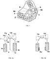
- Fig 1 shows a custom surgical template 1 secured on a patient's dentition 2.
- the surgical template comprises: an opening 3 that coincide with a surgical axis, in this case a drilling and implant axis 13 (see Fig 2 ); two template guide rails 4a, 4b; and two template stops (not visible).
- Each template guide rail 4a, 4b comprises a substantially cylindrical hollow passage 5 and a lateral opening 6 along its length which opens into the hollow passage and into the template opening 3.
- the template guide rails 4a, 4b are retained by part of a template frame, notably comprising a series of template struts.
- the open form of the template frame facilitates accessibility and visibility for the surgical site which in this example is a site at the jaw bone located between the template guide rails 4a, 4b.
- the illustrated surgical template is shown for drilling a single bore.
- the surgical template is configured for providing two or more spaced bores, the position of each desired bore being provided by respective template guide rails.
- Fig 2a shows an enlarged view of a first embodiment of template guide rails 4a, 4b and a handpiece jig 7 adapted to cooperate with the template guide rails.
- Template stops 8 are located towards the bottom of the template guide rails.
- the handpiece jig comprises: an attachment ring 9 adapted to be secured to a surgical handpiece, in this case a dental drilling handpiece; two supporting flanges 10a,10b projecting from the attachment ring; and two male type handpiece guides 11a, 11b each of which is adapted to be slidably received in a respective one of the female type template guides 4a,4b during the surgical intervention.
- Each of the two handpiece guides 11a, 11b is attached to a respective supporting flange 10a, 10b of the handpiece jig; a portion of each supporting flange 10a, 10b is adapted to be slidably received in the lateral opening 8 of its respective template guide rails 4a, 4b during the surgical intervention.
- a handpiece stop 12a,12b is provided at each supporting flange. As illustrated in Fig 2a , the handpiece stops 12a, 12b may be provided at or towards a lower portion of the supporting flange(s), notably by a lower surface of the supporting flange(s).
- each supporting flange 10a, 10b may be attached to its respective handpiece guide 11a, 11b along substantially the entire length of its handpiece guide 11a, 11b; this assists in providing mechanical stability.
- Each supporting flange may rise, notably in an arc, from a lower portion to an upper portion at which it is attached to the attachment ring 9 so as to provide a greater separation between the two flanges at their lower portions compared with the opening at their upper portions; this again contributes to accessibility and visibility for the surgical site, particularly for a surgical intervention in a patient's jaw bone.
- Fig 2b illustrates an alternative embodiment in which the handpiece jig 7 comprises handpiece stops 14a, 14b, at or towards the top of each supporting flange and the template guide rails 4a, 4b comprise template stops 15a, 15b which are located at the exterior of the template guide rails 4a, 4b.
- each handpiece guide is preferably associated with a pair of handpiece stops, for example a first handpiece stop 14a positioned at a front face of the flange 10a and a second handpiece stop (not shown) positioned at a corresponding position at a rear face of the flange 10a.
- Each such handpiece stop cooperates with an associated template stop, for example, a pair of template stops 15a located either side of a lateral opening 8 or slot of the template guide 4a.
- Fig 3 sequential positions of the handpiece guide 11a, 11b of Fig 2a are shown in use during a drilling procedure. For clarity other portions of the surgical template are not shown. Notably, this illustrates engagement and sliding progression of the handpiece guides 11a, 11b of the handpiece jig 7 within the template guide rails 4a, 4b and penetration of a drill bit 16 into the jaw bone 17 to create a desired bore.
- the two template guide rails are located on either side of the gingiva and jaw bone and the bottom of the template guide rails 18 are positioned at a level below the upper position of the gingiva 19 and corresponding jaw bone 17.
- the drill can be slid towards the surgical site guided by the surgical template and the handpiece jig.
- the maximum depth of the handpiece jig relative to the surgical template, and thus the maximum depth bore drilled, is fixed by contact between the template stops 8a, 8b and the handpiece stop 12a,12b.
- Fig 4 shows corresponding positions of a handpiece guides 11a, 11b during a drilling procedure using the system of Fig 2b ; the maximum depth of the handpiece jig relative to the surgical template, and thus the maximum depth bore drilled, is fixed by contact 20 between the template stops 15a, 15b and the handpiece stop 14a,14b.
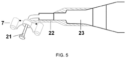
- Fig 5 shows a piezotome tip 21 and a handpiece jig 7 secured to a surgical handpiece 23, in this embodiment through a suitable connecting piece 22.
Landscapes
- Health & Medical Sciences (AREA)
- Oral & Maxillofacial Surgery (AREA)
- Dentistry (AREA)
- Life Sciences & Earth Sciences (AREA)
- Animal Behavior & Ethology (AREA)
- General Health & Medical Sciences (AREA)
- Public Health (AREA)
- Veterinary Medicine (AREA)
- Epidemiology (AREA)
- Orthopedic Medicine & Surgery (AREA)
- Surgery (AREA)
- Nuclear Medicine, Radiotherapy & Molecular Imaging (AREA)
- Engineering & Computer Science (AREA)
- Biomedical Technology (AREA)
- Heart & Thoracic Surgery (AREA)
- Medical Informatics (AREA)
- Molecular Biology (AREA)
- Dental Tools And Instruments Or Auxiliary Dental Instruments (AREA)
- Dental Prosthetics (AREA)
- Orthopedics, Nursing, And Contraception (AREA)
- Surgical Instruments (AREA)
Priority Applications (1)
| Application Number | Priority Date | Filing Date | Title |
|---|---|---|---|
| PL16809069T PL3389546T3 (pl) | 2015-12-14 | 2016-12-12 | Układ prowadnika chirurgii stomatologicznej |
Applications Claiming Priority (2)
| Application Number | Priority Date | Filing Date | Title |
|---|---|---|---|
| LU92907A LU92907B1 (en) | 2015-12-14 | 2015-12-14 | Dental surgery guide system |
| PCT/EP2016/080635 WO2017102646A1 (en) | 2015-12-14 | 2016-12-12 | Dental surgery guide system |
Publications (2)
| Publication Number | Publication Date |
|---|---|
| EP3389546A1 EP3389546A1 (en) | 2018-10-24 |
| EP3389546B1 true EP3389546B1 (en) | 2021-03-24 |
Family
ID=55080147
Family Applications (1)
| Application Number | Title | Priority Date | Filing Date |
|---|---|---|---|
| EP16809069.4A Active EP3389546B1 (en) | 2015-12-14 | 2016-12-12 | Dental surgery guide system |
Country Status (18)
| Country | Link |
|---|---|
| US (1) | US11376099B2 (pl) |
| EP (1) | EP3389546B1 (pl) |
| JP (1) | JP6842193B2 (pl) |
| KR (1) | KR102641675B1 (pl) |
| CN (1) | CN108366842B (pl) |
| AU (1) | AU2016372260B2 (pl) |
| BR (1) | BR112018012046B1 (pl) |
| CA (1) | CA3008189A1 (pl) |
| ES (1) | ES2874648T3 (pl) |
| IL (1) | IL259926B (pl) |
| LU (1) | LU92907B1 (pl) |
| MA (1) | MA44045B1 (pl) |
| MX (1) | MX2018007305A (pl) |
| PL (1) | PL3389546T3 (pl) |
| RU (1) | RU2721294C2 (pl) |
| SG (1) | SG11201804762YA (pl) |
| WO (1) | WO2017102646A1 (pl) |
| ZA (1) | ZA201803866B (pl) |
Families Citing this family (4)
| Publication number | Priority date | Publication date | Assignee | Title |
|---|---|---|---|---|
| CN110897740B (zh) * | 2019-12-05 | 2020-08-04 | 广州景安宏悦医疗科技有限公司 | 栓道式种植体导向定位器 |
| KR102566293B1 (ko) * | 2020-09-28 | 2023-08-18 | 서울대학교산학협력단 | 구강경유 수술을 위한 보호 장치 |
| RU2758099C1 (ru) * | 2021-03-04 | 2021-10-26 | Федеральное государственное бюджетное образовательное учреждение высшего образования "Рязанский государственный медицинский университет имени академика И.П. Павлова" Министерства здравоохранения Российской Федерации | Навигационный шаблон для дентальной имплантации с каналом для ирригации операционного поля |
| EP4413947A1 (en) | 2023-02-07 | 2024-08-14 | Biotechnology Institute, I MAS D, S.L. | Guidance system for implant placement |
Family Cites Families (26)
| Publication number | Priority date | Publication date | Assignee | Title |
|---|---|---|---|---|
| US5133660A (en) * | 1989-08-07 | 1992-07-28 | Fenick Thomas J | Device for locating the optimum position for a tooth implant |
| DE19624381A1 (de) * | 1996-06-19 | 1998-01-02 | Lauks Nikola | Bohrlehre für kieferchirurgische Implantatkavitäten |
| RU2233138C1 (ru) * | 2003-04-24 | 2004-07-27 | Роговский Юрий Михайлович | Стоматологический наконечник (варианты) |
| DE102004022778B4 (de) * | 2004-05-08 | 2007-10-04 | Alfred Schaffner | Zahnkeil |
| FR2896403B1 (fr) * | 2006-01-24 | 2008-08-01 | Francois Blouzard | Dispositif de guidage d'outil de percage pour la mise en place d'au moins un implant dentaire |
| WO2008006802A1 (fr) * | 2006-07-11 | 2008-01-17 | 2Ingis S.A. | Procede de fabrication d'une prothese osseuse ou d'une simulation preimplantaire et appareillage mis en oeuvre |
| BRPI0807186B8 (pt) * | 2007-01-26 | 2021-06-22 | Friadent Gmbh | disposição com um instrumento para a preparação ou execução da inserção de um implante |
| US20080220390A1 (en) * | 2007-03-07 | 2008-09-11 | Michael Klein | Dental tool guide assembly |
| JP5467726B2 (ja) * | 2007-09-12 | 2014-04-09 | イマグノーシス株式会社 | インプラント植立用穿孔器具、ハンドピース、ハンドピース用アダプタおよびサージカルガイド |
| CN101801304A (zh) * | 2007-09-12 | 2010-08-11 | 画像诊断株式会社 | 植体植入用穿孔器具、手机、手机用适配器以及手术导板 |
| JP2009207688A (ja) * | 2008-03-04 | 2009-09-17 | Imagunooshisu Kk | インプラント植立用穿孔器具およびインプラント用ハンドピース |
| KR100884211B1 (ko) * | 2008-06-26 | 2009-02-18 | 이달호 | 상악동 거상 시술용 피조톰 |
| FR2942953B1 (fr) * | 2009-03-16 | 2011-12-16 | Francois Paul Henry Blouzard | Dispositif prefabrique de positionnement d'un moyen de guidage du percage en implantologie dentaire |
| US8899984B2 (en) * | 2009-05-20 | 2014-12-02 | Daniel R. Llop | CT-based, side-loading surgical and laboratory dental implant guide system and method |
| WO2011091382A1 (en) * | 2010-01-22 | 2011-07-28 | Precision Through Imaging, Llc | Dental implantation system and method |
| CN101828974B (zh) * | 2010-05-27 | 2012-12-19 | 南京医科大学附属口腔医院 | 种植义齿个性化定位导板的制造方法 |
| CN202288506U (zh) * | 2011-08-18 | 2012-07-04 | 杭州正驰达精密机械有限公司 | 一种横向进入式种牙导板 |
| TW201325563A (zh) * | 2011-12-16 | 2013-07-01 | Metal Ind Res & Dev Ct | 植牙導引裝置 |
| JP3176616U (ja) * | 2012-04-04 | 2012-06-28 | 博彦 北村 | インプラント穴形成用ドリル |
| CN202892124U (zh) * | 2012-11-21 | 2013-04-24 | 赵鑫 | 牙种植体植入平行定位装置 |
| CN103876805B (zh) * | 2012-12-21 | 2016-03-09 | 林协兴 | 骨骼钻孔用定位导引装置 |
| CN203291051U (zh) * | 2013-02-27 | 2013-11-20 | 杭州六维齿科医疗技术有限公司 | 一种用于牙种植术的定位导向系统 |
| US9693834B2 (en) * | 2013-09-13 | 2017-07-04 | National Dentex, Llc | Implant-based attachment system for dental implant surgical guide and method |
| KR101501236B1 (ko) * | 2013-11-27 | 2015-03-12 | 연세대학교 산학협력단 | 치과 임플란트용 드릴의 가이드 장치 |
| CN203619704U (zh) * | 2013-12-04 | 2014-06-04 | 杭州六维齿科医疗技术有限公司 | 全牙缺失的牙种植手术导板 |
| KR101478720B1 (ko) * | 2014-02-18 | 2015-01-02 | 연세대학교 산학협력단 | 치과 드릴의 가이드 장치 및 스텐트의 제조방법 |
-
2015
- 2015-12-14 LU LU92907A patent/LU92907B1/en active IP Right Grant
-
2016
- 2016-12-12 US US16/061,878 patent/US11376099B2/en active Active
- 2016-12-12 BR BR112018012046-4A patent/BR112018012046B1/pt active IP Right Grant
- 2016-12-12 ES ES16809069T patent/ES2874648T3/es active Active
- 2016-12-12 KR KR1020187019839A patent/KR102641675B1/ko active Active
- 2016-12-12 MA MA44045A patent/MA44045B1/fr unknown
- 2016-12-12 EP EP16809069.4A patent/EP3389546B1/en active Active
- 2016-12-12 RU RU2018125833A patent/RU2721294C2/ru active
- 2016-12-12 AU AU2016372260A patent/AU2016372260B2/en active Active
- 2016-12-12 CN CN201680073686.4A patent/CN108366842B/zh active Active
- 2016-12-12 WO PCT/EP2016/080635 patent/WO2017102646A1/en not_active Ceased
- 2016-12-12 JP JP2018549617A patent/JP6842193B2/ja active Active
- 2016-12-12 MX MX2018007305A patent/MX2018007305A/es unknown
- 2016-12-12 PL PL16809069T patent/PL3389546T3/pl unknown
- 2016-12-12 SG SG11201804762YA patent/SG11201804762YA/en unknown
- 2016-12-12 CA CA3008189A patent/CA3008189A1/en active Pending
-
2018
- 2018-06-10 IL IL259926A patent/IL259926B/en unknown
- 2018-06-11 ZA ZA2018/03866A patent/ZA201803866B/en unknown
Non-Patent Citations (1)
| Title |
|---|
| None * |
Also Published As
| Publication number | Publication date |
|---|---|
| RU2018125833A3 (pl) | 2020-03-13 |
| JP2018537256A (ja) | 2018-12-20 |
| RU2721294C2 (ru) | 2020-05-18 |
| SG11201804762YA (en) | 2018-07-30 |
| US20180368937A1 (en) | 2018-12-27 |
| BR112018012046B1 (pt) | 2021-08-03 |
| IL259926A (en) | 2018-07-31 |
| PL3389546T3 (pl) | 2021-10-25 |
| RU2018125833A (ru) | 2020-01-16 |
| AU2016372260B2 (en) | 2022-01-27 |
| ES2874648T3 (es) | 2021-11-05 |
| JP6842193B2 (ja) | 2021-03-17 |
| CA3008189A1 (en) | 2017-06-22 |
| CN108366842B (zh) | 2020-12-29 |
| MX2018007305A (es) | 2018-11-09 |
| ZA201803866B (en) | 2019-03-27 |
| CN108366842A (zh) | 2018-08-03 |
| WO2017102646A1 (en) | 2017-06-22 |
| BR112018012046A2 (pt) | 2018-12-04 |
| EP3389546A1 (en) | 2018-10-24 |
| IL259926B (en) | 2022-02-01 |
| KR20180109878A (ko) | 2018-10-08 |
| MA44045B1 (fr) | 2021-06-30 |
| AU2016372260A1 (en) | 2018-07-05 |
| KR102641675B1 (ko) | 2024-02-29 |
| US11376099B2 (en) | 2022-07-05 |
| LU92907B1 (en) | 2017-08-09 |
Similar Documents
| Publication | Publication Date | Title |
|---|---|---|
| AU2007274381B2 (en) | Method for producing a bone prosthesis or a pre-implant simulation, and equipment used | |
| US7824181B2 (en) | Custom-fit implant surgery guide and associated milling cutter, method for their production, and their use | |
| EP2196162B1 (en) | Drill guide | |
| KR102646499B1 (ko) | 맞춤형 치아 임플란트 및 관련 툴 | |
| EP3389546B1 (en) | Dental surgery guide system | |
| US20140205968A1 (en) | Sleeve for Cutting Bur for Dental Cutting Guide | |
| US9050665B2 (en) | Modular template for drilling holes and method of making same | |
| EP3817685B1 (en) | Surgical guide for zygomatic bone implants | |
| WO2014113761A1 (en) | Sleeve for cutting bur for dental cutting guide | |
| HK1263195A1 (en) | Dental surgery guide system | |
| HK1263195B (en) | Dental surgery guide system | |
| EP1890834B1 (en) | Modular template for drilling holes | |
| USRE47368E1 (en) | Modular template for drilling holes and method of making same |
Legal Events
| Date | Code | Title | Description |
|---|---|---|---|
| STAA | Information on the status of an ep patent application or granted ep patent |
Free format text: STATUS: UNKNOWN |
|
| STAA | Information on the status of an ep patent application or granted ep patent |
Free format text: STATUS: THE INTERNATIONAL PUBLICATION HAS BEEN MADE |
|
| PUAI | Public reference made under article 153(3) epc to a published international application that has entered the european phase |
Free format text: ORIGINAL CODE: 0009012 |
|
| STAA | Information on the status of an ep patent application or granted ep patent |
Free format text: STATUS: REQUEST FOR EXAMINATION WAS MADE |
|
| 17P | Request for examination filed |
Effective date: 20180716 |
|
| AK | Designated contracting states |
Kind code of ref document: A1 Designated state(s): AL AT BE BG CH CY CZ DE DK EE ES FI FR GB GR HR HU IE IS IT LI LT LU LV MC MK MT NL NO PL PT RO RS SE SI SK SM TR |
|
| AX | Request for extension of the european patent |
Extension state: BA ME |
|
| DAX | Request for extension of the european patent (deleted) | ||
| RAV | Requested validation state of the european patent: fee paid |
Extension state: MA Effective date: 20180716 |
|
| STAA | Information on the status of an ep patent application or granted ep patent |
Free format text: STATUS: EXAMINATION IS IN PROGRESS |
|
| 17Q | First examination report despatched |
Effective date: 20200107 |
|
| REG | Reference to a national code |
Ref country code: HK Ref legal event code: DE Ref document number: 1263195 Country of ref document: HK |
|
| GRAP | Despatch of communication of intention to grant a patent |
Free format text: ORIGINAL CODE: EPIDOSNIGR1 |
|
| STAA | Information on the status of an ep patent application or granted ep patent |
Free format text: STATUS: GRANT OF PATENT IS INTENDED |
|
| INTG | Intention to grant announced |
Effective date: 20201102 |
|
| GRAS | Grant fee paid |
Free format text: ORIGINAL CODE: EPIDOSNIGR3 |
|
| GRAA | (expected) grant |
Free format text: ORIGINAL CODE: 0009210 |
|
| STAA | Information on the status of an ep patent application or granted ep patent |
Free format text: STATUS: THE PATENT HAS BEEN GRANTED |
|
| AK | Designated contracting states |
Kind code of ref document: B1 Designated state(s): AL AT BE BG CH CY CZ DE DK EE ES FI FR GB GR HR HU IE IS IT LI LT LU LV MC MK MT NL NO PL PT RO RS SE SI SK SM TR |
|
| REG | Reference to a national code |
Ref country code: GB Ref legal event code: FG4D |
|
| REG | Reference to a national code |
Ref country code: CH Ref legal event code: EP |
|
| REG | Reference to a national code |
Ref country code: IE Ref legal event code: FG4D |
|
| REG | Reference to a national code |
Ref country code: DE Ref legal event code: R096 Ref document number: 602016054922 Country of ref document: DE Ref country code: AT Ref legal event code: REF Ref document number: 1373689 Country of ref document: AT Kind code of ref document: T Effective date: 20210415 |
|
| REG | Reference to a national code |
Ref country code: NL Ref legal event code: FP Ref country code: MA Ref legal event code: VAGR Ref document number: 44045 Country of ref document: MA Kind code of ref document: B1 |
|
| REG | Reference to a national code |
Ref country code: GR Ref legal event code: EP Ref document number: 20210401613 Country of ref document: GR Effective date: 20210709 |
|
| REG | Reference to a national code |
Ref country code: LT Ref legal event code: MG9D |
|
| PG25 | Lapsed in a contracting state [announced via postgrant information from national office to epo] |
Ref country code: NO Free format text: LAPSE BECAUSE OF FAILURE TO SUBMIT A TRANSLATION OF THE DESCRIPTION OR TO PAY THE FEE WITHIN THE PRESCRIBED TIME-LIMIT Effective date: 20210624 Ref country code: HR Free format text: LAPSE BECAUSE OF FAILURE TO SUBMIT A TRANSLATION OF THE DESCRIPTION OR TO PAY THE FEE WITHIN THE PRESCRIBED TIME-LIMIT Effective date: 20210324 Ref country code: FI Free format text: LAPSE BECAUSE OF FAILURE TO SUBMIT A TRANSLATION OF THE DESCRIPTION OR TO PAY THE FEE WITHIN THE PRESCRIBED TIME-LIMIT Effective date: 20210324 Ref country code: BG Free format text: LAPSE BECAUSE OF FAILURE TO SUBMIT A TRANSLATION OF THE DESCRIPTION OR TO PAY THE FEE WITHIN THE PRESCRIBED TIME-LIMIT Effective date: 20210624 |
|
| PG25 | Lapsed in a contracting state [announced via postgrant information from national office to epo] |
Ref country code: LV Free format text: LAPSE BECAUSE OF FAILURE TO SUBMIT A TRANSLATION OF THE DESCRIPTION OR TO PAY THE FEE WITHIN THE PRESCRIBED TIME-LIMIT Effective date: 20210324 Ref country code: RS Free format text: LAPSE BECAUSE OF FAILURE TO SUBMIT A TRANSLATION OF THE DESCRIPTION OR TO PAY THE FEE WITHIN THE PRESCRIBED TIME-LIMIT Effective date: 20210324 Ref country code: SE Free format text: LAPSE BECAUSE OF FAILURE TO SUBMIT A TRANSLATION OF THE DESCRIPTION OR TO PAY THE FEE WITHIN THE PRESCRIBED TIME-LIMIT Effective date: 20210324 |
|
| PG25 | Lapsed in a contracting state [announced via postgrant information from national office to epo] |
Ref country code: SM Free format text: LAPSE BECAUSE OF FAILURE TO SUBMIT A TRANSLATION OF THE DESCRIPTION OR TO PAY THE FEE WITHIN THE PRESCRIBED TIME-LIMIT Effective date: 20210324 Ref country code: LT Free format text: LAPSE BECAUSE OF FAILURE TO SUBMIT A TRANSLATION OF THE DESCRIPTION OR TO PAY THE FEE WITHIN THE PRESCRIBED TIME-LIMIT Effective date: 20210324 Ref country code: EE Free format text: LAPSE BECAUSE OF FAILURE TO SUBMIT A TRANSLATION OF THE DESCRIPTION OR TO PAY THE FEE WITHIN THE PRESCRIBED TIME-LIMIT Effective date: 20210324 Ref country code: CZ Free format text: LAPSE BECAUSE OF FAILURE TO SUBMIT A TRANSLATION OF THE DESCRIPTION OR TO PAY THE FEE WITHIN THE PRESCRIBED TIME-LIMIT Effective date: 20210324 |
|
| REG | Reference to a national code |
Ref country code: ES Ref legal event code: FG2A Ref document number: 2874648 Country of ref document: ES Kind code of ref document: T3 Effective date: 20211105 |
|
| PG25 | Lapsed in a contracting state [announced via postgrant information from national office to epo] |
Ref country code: IS Free format text: LAPSE BECAUSE OF FAILURE TO SUBMIT A TRANSLATION OF THE DESCRIPTION OR TO PAY THE FEE WITHIN THE PRESCRIBED TIME-LIMIT Effective date: 20210724 Ref country code: PT Free format text: LAPSE BECAUSE OF FAILURE TO SUBMIT A TRANSLATION OF THE DESCRIPTION OR TO PAY THE FEE WITHIN THE PRESCRIBED TIME-LIMIT Effective date: 20210726 Ref country code: RO Free format text: LAPSE BECAUSE OF FAILURE TO SUBMIT A TRANSLATION OF THE DESCRIPTION OR TO PAY THE FEE WITHIN THE PRESCRIBED TIME-LIMIT Effective date: 20210324 Ref country code: SK Free format text: LAPSE BECAUSE OF FAILURE TO SUBMIT A TRANSLATION OF THE DESCRIPTION OR TO PAY THE FEE WITHIN THE PRESCRIBED TIME-LIMIT Effective date: 20210324 |
|
| REG | Reference to a national code |
Ref country code: DE Ref legal event code: R097 Ref document number: 602016054922 Country of ref document: DE |
|
| PG25 | Lapsed in a contracting state [announced via postgrant information from national office to epo] |
Ref country code: DK Free format text: LAPSE BECAUSE OF FAILURE TO SUBMIT A TRANSLATION OF THE DESCRIPTION OR TO PAY THE FEE WITHIN THE PRESCRIBED TIME-LIMIT Effective date: 20210324 Ref country code: AL Free format text: LAPSE BECAUSE OF FAILURE TO SUBMIT A TRANSLATION OF THE DESCRIPTION OR TO PAY THE FEE WITHIN THE PRESCRIBED TIME-LIMIT Effective date: 20210324 |
|
| PLBE | No opposition filed within time limit |
Free format text: ORIGINAL CODE: 0009261 |
|
| STAA | Information on the status of an ep patent application or granted ep patent |
Free format text: STATUS: NO OPPOSITION FILED WITHIN TIME LIMIT |
|
| PG25 | Lapsed in a contracting state [announced via postgrant information from national office to epo] |
Ref country code: SI Free format text: LAPSE BECAUSE OF FAILURE TO SUBMIT A TRANSLATION OF THE DESCRIPTION OR TO PAY THE FEE WITHIN THE PRESCRIBED TIME-LIMIT Effective date: 20210324 |
|
| 26N | No opposition filed |
Effective date: 20220104 |
|
| PG25 | Lapsed in a contracting state [announced via postgrant information from national office to epo] |
Ref country code: IS Free format text: LAPSE BECAUSE OF FAILURE TO SUBMIT A TRANSLATION OF THE DESCRIPTION OR TO PAY THE FEE WITHIN THE PRESCRIBED TIME-LIMIT Effective date: 20210724 |
|
| PG25 | Lapsed in a contracting state [announced via postgrant information from national office to epo] |
Ref country code: MC Free format text: LAPSE BECAUSE OF FAILURE TO SUBMIT A TRANSLATION OF THE DESCRIPTION OR TO PAY THE FEE WITHIN THE PRESCRIBED TIME-LIMIT Effective date: 20210324 |
|
| PG25 | Lapsed in a contracting state [announced via postgrant information from national office to epo] |
Ref country code: IE Free format text: LAPSE BECAUSE OF NON-PAYMENT OF DUE FEES Effective date: 20211212 |
|
| REG | Reference to a national code |
Ref country code: AT Ref legal event code: UEP Ref document number: 1373689 Country of ref document: AT Kind code of ref document: T Effective date: 20210324 |
|
| PG25 | Lapsed in a contracting state [announced via postgrant information from national office to epo] |
Ref country code: HU Free format text: LAPSE BECAUSE OF FAILURE TO SUBMIT A TRANSLATION OF THE DESCRIPTION OR TO PAY THE FEE WITHIN THE PRESCRIBED TIME-LIMIT; INVALID AB INITIO Effective date: 20161212 |
|
| P01 | Opt-out of the competence of the unified patent court (upc) registered |
Effective date: 20230505 |
|
| PG25 | Lapsed in a contracting state [announced via postgrant information from national office to epo] |
Ref country code: CY Free format text: LAPSE BECAUSE OF FAILURE TO SUBMIT A TRANSLATION OF THE DESCRIPTION OR TO PAY THE FEE WITHIN THE PRESCRIBED TIME-LIMIT Effective date: 20210324 |
|
| PG25 | Lapsed in a contracting state [announced via postgrant information from national office to epo] |
Ref country code: MK Free format text: LAPSE BECAUSE OF FAILURE TO SUBMIT A TRANSLATION OF THE DESCRIPTION OR TO PAY THE FEE WITHIN THE PRESCRIBED TIME-LIMIT Effective date: 20210324 |
|
| PG25 | Lapsed in a contracting state [announced via postgrant information from national office to epo] |
Ref country code: MT Free format text: LAPSE BECAUSE OF FAILURE TO SUBMIT A TRANSLATION OF THE DESCRIPTION OR TO PAY THE FEE WITHIN THE PRESCRIBED TIME-LIMIT Effective date: 20210324 |
|
| PGFP | Annual fee paid to national office [announced via postgrant information from national office to epo] |
Ref country code: DE Payment date: 20241227 Year of fee payment: 9 |
|
| PGFP | Annual fee paid to national office [announced via postgrant information from national office to epo] |
Ref country code: ES Payment date: 20250102 Year of fee payment: 9 |
|
| PGFP | Annual fee paid to national office [announced via postgrant information from national office to epo] |
Ref country code: CH Payment date: 20250108 Year of fee payment: 9 |
|
| VSFP | Annual fee paid to validation state [announced via postgrant information from national office to epo] |
Ref country code: MA Payment date: 20231129 Year of fee payment: 8 |
|
| VSFP | Annual fee paid to validation state [announced via postgrant information from national office to epo] |
Ref country code: MA Payment date: 20230103 Year of fee payment: 7 Ref country code: MA Payment date: 20211125 Year of fee payment: 6 |
|
| VSFP | Annual fee paid to validation state [announced via postgrant information from national office to epo] |
Ref country code: MA Payment date: 20241210 Year of fee payment: 9 |
|
| REG | Reference to a national code |
Ref country code: CH Ref legal event code: U11 Free format text: ST27 STATUS EVENT CODE: U-0-0-U10-U11 (AS PROVIDED BY THE NATIONAL OFFICE) Effective date: 20260101 |
|
| PGFP | Annual fee paid to national office [announced via postgrant information from national office to epo] |
Ref country code: GB Payment date: 20251229 Year of fee payment: 10 |
|
| PGFP | Annual fee paid to national office [announced via postgrant information from national office to epo] |
Ref country code: AT Payment date: 20251230 Year of fee payment: 10 |
|
| PGFP | Annual fee paid to national office [announced via postgrant information from national office to epo] |
Ref country code: IT Payment date: 20251219 Year of fee payment: 10 |
|
| PGFP | Annual fee paid to national office [announced via postgrant information from national office to epo] |
Ref country code: LU Payment date: 20251229 Year of fee payment: 10 Ref country code: FR Payment date: 20251226 Year of fee payment: 10 Ref country code: NL Payment date: 20251226 Year of fee payment: 10 |
|
| PGFP | Annual fee paid to national office [announced via postgrant information from national office to epo] |
Ref country code: GR Payment date: 20251230 Year of fee payment: 10 Ref country code: BE Payment date: 20251229 Year of fee payment: 10 Ref country code: TR Payment date: 20251202 Year of fee payment: 10 |
|
| PGFP | Annual fee paid to national office [announced via postgrant information from national office to epo] |
Ref country code: PL Payment date: 20251203 Year of fee payment: 10 |
|
| VSFP | Annual fee paid to validation state [announced via postgrant information from national office to epo] |
Ref country code: MA Payment date: 20251225 Year of fee payment: 10 |