EP3388639A2 - Messvorrichtung und messverfahren für eine strömung - Google Patents
Messvorrichtung und messverfahren für eine strömung Download PDFInfo
- Publication number
- EP3388639A2 EP3388639A2 EP18163384.3A EP18163384A EP3388639A2 EP 3388639 A2 EP3388639 A2 EP 3388639A2 EP 18163384 A EP18163384 A EP 18163384A EP 3388639 A2 EP3388639 A2 EP 3388639A2
- Authority
- EP
- European Patent Office
- Prior art keywords
- flow
- measuring device
- fluid
- fluid channel
- suction opening
- Prior art date
- Legal status (The legal status is an assumption and is not a legal conclusion. Google has not performed a legal analysis and makes no representation as to the accuracy of the status listed.)
- Granted
Links
Images



Classifications
-
- F—MECHANICAL ENGINEERING; LIGHTING; HEATING; WEAPONS; BLASTING
- F01—MACHINES OR ENGINES IN GENERAL; ENGINE PLANTS IN GENERAL; STEAM ENGINES
- F01D—NON-POSITIVE DISPLACEMENT MACHINES OR ENGINES, e.g. STEAM TURBINES
- F01D21/00—Shutting-down of machines or engines, e.g. in emergency; Regulating, controlling, or safety means not otherwise provided for
- F01D21/003—Arrangements for testing or measuring
-
- F—MECHANICAL ENGINEERING; LIGHTING; HEATING; WEAPONS; BLASTING
- F01—MACHINES OR ENGINES IN GENERAL; ENGINE PLANTS IN GENERAL; STEAM ENGINES
- F01D—NON-POSITIVE DISPLACEMENT MACHINES OR ENGINES, e.g. STEAM TURBINES
- F01D17/00—Regulating or controlling by varying flow
- F01D17/02—Arrangement of sensing elements
- F01D17/08—Arrangement of sensing elements responsive to condition of working-fluid, e.g. pressure
-
- G—PHYSICS
- G01—MEASURING; TESTING
- G01F—MEASURING VOLUME, VOLUME FLOW, MASS FLOW OR LIQUID LEVEL; METERING BY VOLUME
- G01F1/00—Measuring the volume flow or mass flow of fluid or fluent solid material wherein the fluid passes through a meter in a continuous flow
- G01F1/05—Measuring the volume flow or mass flow of fluid or fluent solid material wherein the fluid passes through a meter in a continuous flow by using mechanical effects
- G01F1/34—Measuring the volume flow or mass flow of fluid or fluent solid material wherein the fluid passes through a meter in a continuous flow by using mechanical effects by measuring pressure or differential pressure
- G01F1/36—Measuring the volume flow or mass flow of fluid or fluent solid material wherein the fluid passes through a meter in a continuous flow by using mechanical effects by measuring pressure or differential pressure the pressure or differential pressure being created by the use of flow constriction
- G01F1/40—Details of construction of the flow constriction devices
- G01F1/46—Pitot tubes
-
- G—PHYSICS
- G01—MEASURING; TESTING
- G01L—MEASURING FORCE, STRESS, TORQUE, WORK, MECHANICAL POWER, MECHANICAL EFFICIENCY, OR FLUID PRESSURE
- G01L19/00—Details of, or accessories for, apparatus for measuring steady or quasi-steady pressure of a fluent medium insofar as such details or accessories are not special to particular types of pressure gauges
-
- G—PHYSICS
- G01—MEASURING; TESTING
- G01M—TESTING STATIC OR DYNAMIC BALANCE OF MACHINES OR STRUCTURES; TESTING OF STRUCTURES OR APPARATUS, NOT OTHERWISE PROVIDED FOR
- G01M15/00—Testing of engines
- G01M15/14—Testing gas-turbine engines or jet-propulsion engines
-
- G—PHYSICS
- G01—MEASURING; TESTING
- G01M—TESTING STATIC OR DYNAMIC BALANCE OF MACHINES OR STRUCTURES; TESTING OF STRUCTURES OR APPARATUS, NOT OTHERWISE PROVIDED FOR
- G01M3/00—Investigating fluid-tightness of structures
- G01M3/02—Investigating fluid-tightness of structures by using fluid or vacuum
- G01M3/26—Investigating fluid-tightness of structures by using fluid or vacuum by measuring rate of loss or gain of fluid, e.g. by pressure-responsive devices, by flow detectors
-
- F—MECHANICAL ENGINEERING; LIGHTING; HEATING; WEAPONS; BLASTING
- F05—INDEXING SCHEMES RELATING TO ENGINES OR PUMPS IN VARIOUS SUBCLASSES OF CLASSES F01-F04
- F05D—INDEXING SCHEME FOR ASPECTS RELATING TO NON-POSITIVE-DISPLACEMENT MACHINES OR ENGINES, GAS-TURBINES OR JET-PROPULSION PLANTS
- F05D2220/00—Application
- F05D2220/30—Application in turbines
- F05D2220/32—Application in turbines in gas turbines
- F05D2220/323—Application in turbines in gas turbines for aircraft propulsion, e.g. jet engines
-
- F—MECHANICAL ENGINEERING; LIGHTING; HEATING; WEAPONS; BLASTING
- F05—INDEXING SCHEMES RELATING TO ENGINES OR PUMPS IN VARIOUS SUBCLASSES OF CLASSES F01-F04
- F05D—INDEXING SCHEME FOR ASPECTS RELATING TO NON-POSITIVE-DISPLACEMENT MACHINES OR ENGINES, GAS-TURBINES OR JET-PROPULSION PLANTS
- F05D2220/00—Application
- F05D2220/40—Application in turbochargers
-
- F—MECHANICAL ENGINEERING; LIGHTING; HEATING; WEAPONS; BLASTING
- F05—INDEXING SCHEMES RELATING TO ENGINES OR PUMPS IN VARIOUS SUBCLASSES OF CLASSES F01-F04
- F05D—INDEXING SCHEME FOR ASPECTS RELATING TO NON-POSITIVE-DISPLACEMENT MACHINES OR ENGINES, GAS-TURBINES OR JET-PROPULSION PLANTS
- F05D2270/00—Control
- F05D2270/30—Control parameters, e.g. input parameters
- F05D2270/301—Pressure
-
- F—MECHANICAL ENGINEERING; LIGHTING; HEATING; WEAPONS; BLASTING
- F05—INDEXING SCHEMES RELATING TO ENGINES OR PUMPS IN VARIOUS SUBCLASSES OF CLASSES F01-F04
- F05D—INDEXING SCHEME FOR ASPECTS RELATING TO NON-POSITIVE-DISPLACEMENT MACHINES OR ENGINES, GAS-TURBINES OR JET-PROPULSION PLANTS
- F05D2270/00—Control
- F05D2270/30—Control parameters, e.g. input parameters
- F05D2270/303—Temperature
-
- F—MECHANICAL ENGINEERING; LIGHTING; HEATING; WEAPONS; BLASTING
- F05—INDEXING SCHEMES RELATING TO ENGINES OR PUMPS IN VARIOUS SUBCLASSES OF CLASSES F01-F04
- F05D—INDEXING SCHEME FOR ASPECTS RELATING TO NON-POSITIVE-DISPLACEMENT MACHINES OR ENGINES, GAS-TURBINES OR JET-PROPULSION PLANTS
- F05D2270/00—Control
- F05D2270/30—Control parameters, e.g. input parameters
- F05D2270/306—Mass flow
-
- F—MECHANICAL ENGINEERING; LIGHTING; HEATING; WEAPONS; BLASTING
- F05—INDEXING SCHEMES RELATING TO ENGINES OR PUMPS IN VARIOUS SUBCLASSES OF CLASSES F01-F04
- F05D—INDEXING SCHEME FOR ASPECTS RELATING TO NON-POSITIVE-DISPLACEMENT MACHINES OR ENGINES, GAS-TURBINES OR JET-PROPULSION PLANTS
- F05D2270/00—Control
- F05D2270/30—Control parameters, e.g. input parameters
- F05D2270/311—Air humidity
Definitions
- the invention relates to a measuring device for a flow having the features of claim 1 and a measuring method for a flow having the features of claim 14.
- boundary layers A characteristic of frictional flows is the formation of so-called boundary layers.
- the boundary layer comprises the compared to the core flow pulse-poorer fluid that occurs due to friction (eg on bodies in the flow), but also as a result of rotational or centrifugal forces. This results in particular in rotation-induced boundary layers circumferential variations with very large amplitude, which make accurate and low-fluctuation characterization of Kavticiansströmung or impossible.
- At least one aspiration opening serves for purposeful aspiration of fluid from a region of a mixed flow, wherein the at least one aspiration opening is spaced from a wall delimiting the flow and fluid drawn in via a fluid channel can be guided to a sensor device.
- the fluid channel is designed so that the inflow of the sucked mixed fluid takes place without accumulation.
- the fluid channel can have a section through which the fluid flows simply, wherein fluid can then be branched off from the section to the sensor device.
- the suction opening is formed substantially parallel to the main flow direction.
- the at least one suction opening can be arranged on the fluid channel of the measuring device, wherein the fluid channel is formed at least partially straight or curved.
- the cross section of the at least one suction opening may be round or elliptical.
- At least one suction opening can be arranged on the circumference of the fluid channel.
- two suction openings can be arranged at a distance between 90 ° and 120 °.
- the ratio between the free length of the fluid channel in the flow and the characteristic diameter of the fluid channel can be between 0.5 and 1.5, in particular at 1.
- the free length of the fluid channel in the flow corresponds to 2 to 10 times the boundary layer thickness forming during operation. This should minimize the boundary layer influences on the measurement result.
- the at least one intake opening can be arranged parallel to a main flow direction or at an angle, in particular at an angle between 70 ° and 110 °, in particular between 85 ° and 105 °, very particularly at an angle of 90 ° to the main flow direction.
- the pressure difference between the mixed flow and the sensor device is between 1.2 and 1.5, in particular at 1.4. This ensures sufficient flow.
- the sensor device is designed as a temperature sensor, as a sensor for measuring the concentration of at least one substance, as a sensor for determining the particle size of a particulate flow, as a sensor for determining the humidity, as a sensor for determining the oil content in a gas and / or pressure sensor ,
- a typical metered fluid metering device is located between a vane and a blade, at the leading edge of a wing, in a turbocharger or a windmill.
- the measuring device for particle measurements in the exhaust gas of diesel vehicles, for particle measurements to control the purity of laboratory facilities (clean rooms) or for measurements of oil and / or the concentrations of other substances in drinking water to ensure drinking water quality and provided.
- a turbomachine in particular an aircraft engine with at least one flow measuring device according to at least one of claims 1 to 11 are equipped.
- the at least one measuring device can be arranged in an air guidance system and / or a hot gas path of the compressor and / or the turbine.
- the object is also achieved by a measuring method having the features of claim 14.
- Such a measuring method may e.g. for particle measurements in exhaust gas from diesel vehicles, for particle measurements to control the purity of laboratory facilities (clean rooms) or for measurements of oil and / or the concentrations of other substances in drinking water to ensure drinking water quality.
- the measuring method is provided for a flow in a turbomachine, in particular in an aircraft engine.
- Fig. 1 1 shows a measuring device 10 for a flow in a turbomachine, in particular in an aircraft engine, with which effects of a boundary layer GS on the measurement result can be minimized.
- boundary layer GS forms here in operation directly on a wall 5.
- a typical boundary layer thickness of a jet engine flow is in the range of 0.5 mm.
- the main flow direction HS is in Fig. 1 plotted - forms an area of the mixed flow AS.
- an intake opening 1 is used to draw in fluid from the region of the mixed flow AS, wherein the at least one intake opening 1 is spaced from the flow-limiting wall 5 and fluid sucked in via a fluid channel 2 - without impounding in the interior of the fluid channel 2 - to a sensor device 3 (eg a temperature measuring device) is performed.
- a sensor device 3 eg a temperature measuring device
- the fluid channel 2 projects with the suction opening 1 at the top as a kind of snorkel into the flow.
- the ratio between the free length (ie the spacing B of the suction opening 1 from the wall 5) of the fluid channel 2 in the flow and the characteristic diameter of the fluid channel 2 may be between 0.5 and 1.5, especially at 1. This free length can also be 2- to 10-fold of the forming during operation boundary layer.
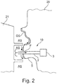
- a concrete application example is the monitoring of the turbine cooling air temperature, which in Fig. 2 is shown schematically.
- the intermediate space between a guide blade 20 and a rotor blade 21 is shown, in which a mixed flow AS has formed in the middle region of the intermediate space.
- a boundary layer GS is formed on the wall 5 for the flow.
- the current state of the art provides systems whose inlet channel is flush with the wall and thus sucks fluid from the metal surface of the flow-limiting walls.
- the measurement of fluid properties such as fluid temperature is influenced by highly three-dimensional boundary layer effects.
- the high variability then contributes to the fact that a high safety factor must be provided.
- the suction of the fluid from the mixed flow AS is not flush with the wall but with a suction opening 1 at the tip of a fluid channel 2.
- the fluid channel 2 - implemented here in the form of a small tube - projects into the core flow (mixed flow AS) and settles in a defined manner from the metal surface of the fluid-limiting wall 5.
- FIG. 3A, 3B is the principal embodiment according to Fig. 1 and 2 in a sectional view ( Fig. 3A ) and a perspective view ( Fig. 3B ), so that the description of the Fig. 1 and 2 Reference can be made.
- Fig. 3B it is shown that the fluid channel 2 projects with the intake opening 1 in the main flow HS with the mixed flow AS. Also is in the Fig. 3A the spacing B from the wall 5 recognizable.
- the suction opening 1 is here aligned parallel to the main flow HS, i. at an angle of 0 °.
- the suction opening 1 in the direction of the main flow direction HS ie between the cross-sectional area of the A and the main flow direction HS is an angle of 90 °.
- the angle between the cross-sectional area of the suction opening 1 and the main flow direction HS can also be between 0 ° and 90 °.
- the fluid channel 2 is formed substantially T-shaped, wherein fluid enters through the suction opening 1 and exits again at the opposite end. In the part of the fluid channel lying perpendicularly, the aspirated fluid is guided to the sensor device 3.
- Fig. 4A the spacing B of the suction opening 1 is shown by the wall 5.
- the embodiment according to the Fig. 5A , B not only uses an intake opening 1, but a plurality of intake openings 1, which are arranged on the circumference of a substantially circular-cylindrical flow body.
- the flow body which has a part of the fluid channel 2 inside, is substantially parallel to the main flow direction HS.
- the end 4, in the Hauströmungsutter HS is fluid mechanical optimized, ie it has the lowest possible flow resistance.
- the suction openings 1 are arranged linearly on the outside of the circular-cylindrical flow body.
- the intake openings 1 are arranged radially on the circumference.
- the suction openings can be arranged against each other by an angular offset.
- the fluid channels shown so far were linear (eg Fig. 1 ) or sections linear (eg Fig. 3A, 3B ) educated.
- the fluid channels 2 are formed at least partially curved.
- the fluid channel 2 on the outside may have a different shape than the fluid-carrying part in the interior.
- Fig. 6 a section from the area of a guide vane 20 is shown.
- the fluid channel 2 projects into the mixed flow AS with an intake opening 1.
- the temperature sensor device 3 is disposed inside. Between the mixed flow AS and the sensor device is a pressure ratio between 1.2 and 1.5, in particular at 1.4 on.
Landscapes
- Engineering & Computer Science (AREA)
- Physics & Mathematics (AREA)
- General Physics & Mathematics (AREA)
- Mechanical Engineering (AREA)
- General Engineering & Computer Science (AREA)
- Fluid Mechanics (AREA)
- Chemical & Material Sciences (AREA)
- Combustion & Propulsion (AREA)
- Measuring Temperature Or Quantity Of Heat (AREA)
- Measuring Volume Flow (AREA)
Abstract
Description
- Die Erfindung betrifft eine Messvorrichtung für eine Strömung mit den Merkmalen des Anspruchs 1 und ein Messverfahren für eine Strömung mit den Merkmalen des Anspruchs 14.
- Ein Charakteristikum reibungsbehafteter Strömungen ist die Ausbildung von sogenannten Grenzschichten. Dabei umfasst die Grenzschicht das im Vergleich zur Kernströmung impulsärmere Fluid, das aufgrund von Reibung (z.B. an Körpern in der Strömung), aber auch in Folge von Rotations- oder Zentrifugalkräften auftritt. Hierdurch ergeben sich insbesondere bei rotationsinduzierten Grenzschichten Umfangsvariationen mit sehr großer Amplitude, die eine genaue und schwankungsarme Charakterisierung der Kavitätsströmung erschweren oder unmöglich machen.
- Technische Strömungen sind vielseitig und in den meisten Fällen sehr komplex. Effekte wie zum Beispiel Reibung, Rotations- und Corioliskräfte tragen dazu bei, dass Strömungen Geschwindigkeits-, Druck- und Temperaturgradienten aufweisen. Gerade in Strömungsmaschinen (z.B. einem Flugzeugtriebwerk), in denen hohe Drücke und hohe Rotationsgeschwindigkeiten auftreten, beinhalten Strömungen eine komplexe dreidimensionale Struktur. Ein typischer Fall ist die Labyrinthdichtung zwischen einer Leitschaufel und einer Laufschaufel in einem Flugzeugtriebwerk, die zur Abdichtung von Kavitäten in der Turbine eingesetzt wird. Eine intakte Abdichtung ist dabei essentiell für die Begrenzung der Temperaturbelastung, der die Turbinenscheiben ausgesetzt sind. Zur Überwachung der Dichtfunktion der Labyrinthdichtung wird daher häufig die Lufttemperatur in diesem Bereich gemessen. Im Betrieb bilden sich jedoch auf Grund von Grenzschichteffekten in Umfangsrichtung unterschiedliche Temperaturen aus, was die Anordnung einer Vielzahl von Sensoren erforderlich macht.
- Bei bekannten Strömungsmessvorrichtungen (z.B. in der
US 5,157,914 A , derUS 2014 / 0133963 A1 oder derUS 2014 / 0037430 A1 ) erfolgt ein Absaugen des Fluides aus der Strömung wandbündig, so dass Grenzschichteinflüsse die Messungen beeinflussen und somit eine große Umfangsschwankung zu erwarten ist. - In vielen Fällen ist es somit wünschenswert, den ausgemischten Zustand eines Fluides in einer Strömung zu charakterisieren, d.h. eine von Grenzschichteffekten unbeeinflusste Messung durchführen zu können.
- Die Aufgabe wird durch eine Strömungsmessvorrichtung mit den Merkmalen des Anspruchs 1 gelöst.
- Mindestens eine Einsaugöffnung dient dabei dem gezielten Einsaugen von Fluid aus einem Bereich einer ausgemischten Strömung, wobei die mindestens eine Einsaugöffnung von einer die Strömung begrenzenden Wandung beabstandet ist und über einen Fluidkanal eingesaugtes Fluid zu einer Sensorvorrichtung führbar ist. Der Fluidkanal ist dabei so ausgebildet, dass die Einströmung des eingesaugten ausgemischten Fluids aufstauungsfrei erfolgt. So kann der Fluidkanal z.B. einen Abschnitt aufweisen, der von dem Fluid einfach durchströmt wird, wobei aus diesem Abschnitt dann Fluid zu der Sensorvorrichtung abzweigbar ist. Oder die Einsaugöffnung ist im Wesentlichen parallel zu Hauptströmungsrichtung ausgebildet.
- Damit kann eine konsistente, sehr genaue und schwankungsarme Charakterisierung der Kernströmung durchgeführt werden. Grenzschichteffekte, die insbesondere bei rotationsbedingten Grenzschichten eine Umfangsvariation mit großer Amplitude nach sich ziehen, können hierdurch minimiert werden.
- Dabei kann die mindestens eine Einsaugöffnung an dem Fluidkanal der Messvorrichtung angeordnet sein, wobei der Fluidkanal mindestens abschnittsweise gerade oder gekrümmt ausgebildet ist. Auch kann in einer Ausführungsform der Querschnitt der mindestens einen Einsaugöffnung rund oder elliptisch ausgebildet sein.
- In einer Ausführungsform kann mindestens eine Einsaugöffnung am Umfang des Fluidkanals angeordnet sein. In einer besonderen Ausführungsform können dann insbesondere zwei Einsaugöffnungen unter einem Abstand zwischen 90° und 120° angeordnet sein.
- Zur Minimierung des Einflusses der Grenzschicht kann das Verhältnis zwischen der freien Länge des Fluidkanals in der Strömung und dem charakteristischen Durchmesser des Fluidkanals zwischen 0,5 und 1,5 liegen, insbesondere bei 1.
- Auch ist es möglich, dass die freie Länge des Fluidkanals in der Strömung 2 bis 10 mal der sich im Betrieb ausbildenden Grenzschichtdicke entspricht. Damit sollen die Grenzschichteinflüsse auf das Messergebnis minimiert werden.
- Je nach Strömungsverhältnissen kann die mindestens eine Einsaugöffnung parallel zu einer Hauptströmungsrichtung oder unter einem Winkel, insbesondere unter einem Winkel zwischen 70° und 110°, insbesondere zwischen 85° und 105°, ganz insbesondere unter einem Winkel von 90° zur Hauptströmungsrichtung angeordnet sein.
- In einer weiteren Ausführungsform liegt im Betrieb die Druckdifferenz zwischen der ausgemischten Strömung und der Sensorvorrichtung zwischen 1,2 und 1,5, insbesondere bei 1,4. Damit ist eine ausreichende Durchströmung sichergestellt.
- In einer Ausführungsform ist die Sensorvorrichtung als Temperatursensor, als Sensor zur Messung der Konzentration mindestens einer Substanz, als Sensor zur Bestimmung der Partikelgröße einer partikelbehafteten Strömung, als Sensor zu Bestimmung der Luftfeuchte, als Sensor zur Bestimmung des Ölanteils in einem Gas und / oder Drucksensor ausgebildet.
- Eine typische Messvorrichtung von ausgemischtem Fluid liegt zwischen einer Leitschaufel und einer Laufschaufel, an der Vorderkante eines Flügels, in einem Turbolader oder einem Windrad.
- In einer Ausführungsvariante ist die Messvorrichtung für Partikelmessungen im Abgas von Dieselfahrzeugen, für Partikelmessungen zur Kontrolle der Reinheit von Laboreinrichtungen (Reinräumen) oder für Messungen von Öl und/oder der Konzentrationen anderer Stoffe in Trinkwasser zur Sicherstellung der Trinkwasserqualität eingerichtet und vorgesehen.
- Auch kann eine Turbomaschine, insbesondere ein Flugzeugtriebwerk mit mindestens einer Strömungsmessvorrichtung nach mindestens einem der Ansprüche 1 bis 11 ausgestattet werden. Insbesondere kann die mindestens eine Messvorrichtung in einem Luftleitsystem und / oder einem Heißgaspfad des Kompressors und / oder der Turbine angeordnet sein.
- Die Aufgabe wird auch durch ein Messverfahren mit den Merkmalen des Anspruchs 14 gelöst.
- Ein solches Messverfahren kann z.B. für Partikelmessungen im Abgas von Dieselfahrzeugen, für Partikelmessungen zur Kontrolle der Reinheit von Laboreinrichtungen (Reinräumen) oder für Messungen von Öl und/oder der Konzentrationen anderer Stoffe in Trinkwasser zur Sicherstellung der Trinkwasserqualität verwendet werden.
- In einem Ausführungsbeispiel ist das Messverfahren für eine Strömung in einer Turbomaschine, insbesondere in einem Flugzeugtriebwerk vorgesehen.
- In Zusammenhang mit den in den Figuren dargestellten Ausführungsbeispielen wird die Erfindung erläutert. Dabei zeigt
-
Fig. 1 eine schematische Zeichnung einer Ausführungsform einer Messvorrichtung; -
Fig. 2 eine schematische Schnittansicht einer weiteren Ausführungsform der Messvorrichtung; -
Fig. 3A eine Schnittansicht einer weiteren Ausführungsform der Messvorrichtung -
Fig. 3B eine perspektivische Darstellung der Ausführungsform nachFig. 3A ; -
Fig. 4A eine Schnittansicht einer weiteren Ausführungsform der Messvorrichtung -
Fig. 4B eine perspektivische Darstellung der Ausführungsform nachFig. 4A ; -
Fig. 5A eine Schnittansicht einer weiteren Ausführungsform der Messvorrichtung -
Fig. 5B eine perspektivische Darstellung der Ausführungsform nachFig. 5A ; -
Fig. 6 eine perspektivische Anordnung einer Ausführungsform im Bereich einer Leitschaufel. - Die Charakterisierung des Fluides in komplexen Strömungen ist aus vielerlei Hinsicht relevant für das Verständnis und die Verbesserung von modernen Strömungsmaschinen. In
Fig. 1 ist eine Messvorrichtung 10 für eine Strömung in einer Turbomaschine, insbesondere in einem Flugzeugtriebwerk dargestellt, mit der Effekte einer Grenzschicht GS auf das Messergebnis minierbar sind. - Die Grenzschicht GS bildet sich hier im Betrieb unmittelbar an einer Wandung 5 aus. Eine typische Grenzschichtdicke einer Strömung in einem Flugzeugtriebwerk liegt im Bereich von 0.5 mm.
- Im Kern der Strömung - die Hauptströmungsrichtung HS ist in
Fig. 1 eingezeichnet - bildet sich ein Bereich der ausgemischten Strömung AS aus. - In der hier dargestellten Ausführungsform dient eine Einsaugöffnung 1 dem Einsaugen von Fluid aus dem Bereich der ausgemischten Strömung AS, wobei die mindestens eine Einsaugöffnung 1 von der die Strömung begrenzenden Wandung 5 beabstandet ist und über einen Fluidkanal 2 eingesaugtes Fluid - ohne Aufstauung im Inneren des Fluidkanals 2 - zu einer Sensorvorrichtung 3 (z.B. einer Temperaturmessvorrichtung) geführt ist. Aufstaufrei bedeutet hier insbesondere, dass im Fluidkanal 2 kein Staudruck gemessen wird.
- Somit ragt der Fluidkanal 2 mit der Einsaugöffnung 1 an der Spitze als eine Art Schnorchel in die Strömung hinein. Durch den Abstand der Einsaugöffnung 1 von der Grenzschicht GS werden Grenzschichteffekte bei der Messung minimiert. Das Verhältnis zwischen der freien Länge (d.h. der Beabstandung B der Einsaugöffnung 1 von der Wandung 5) des Fluidkanals 2 in der Strömung und dem charakteristischen Durchmesser des Fluidkanals 2 kann zwischen 0,5 und 1,5 liegen, insbesondere bei 1. Diese freie Länge kann auch das 2- bis 10-fache der sich im Betrieb ausbildenden Grenzschicht betragen.
- Ein konkretes Anwendungsbeispiel ist die Überwachung der Turbinenkühllufttemperatur, das in
Fig. 2 schematisch dargestellt ist. Dabei ist der Zwischenraum zwischen einer Leitschaufel 20 und einer Laufschaufel 21 dargestellt, in dem sich eine im mittleren Bereich des Zwischenraums eine ausgemischte Strömung AS ausgebildet hat. An der Leitschaufel 20 bildet sich an der Wandung 5 für die Strömung eine Grenzschicht GS aus. - Der derzeitige Stand der Technik sieht Systeme vor, deren Eintrittskanal wandbündig abschließt und somit Fluid von der Metalloberfläche der die Strömung begrenzenden Wände absaugt. Hierdurch wird die Messung der Fluideigenschaften wie zum Beispiel der Fluidtemperatur durch hochgradig dreidimensionale Grenzschichteffekte beeinflusst. Es resultieren daher wesentliche Nachteile wie zum Beispiel eine Umfangsvariation mit hoher Amplitude. Dies ist insbesondere dann von Nachteil, wenn die Charakterisierung der Strömung durch Fluidabsaugungen an einigen wenigen auf den Umfang verteilten Positionen erfolgen soll. Die hohe Schwankungsbreite trägt dann dazu bei, dass ein hoher Sicherheitsfaktor vorgehalten werden muss.
- Um eine Reduzierung dieser hohen Umfangsschwankung zu erreichen, erfolgt die Absaugung des Fluides aus der ausgemischten Strömung AS nicht wandbündig sondern mit einem einer Einsaugöffnung 1 an der Spitze eines Fluidkanals 2. Damit wird das Fluid aus dem Kernbereich der Strömung, der ausgemischten Strömung AS, anstatt aus der Grenzschicht GS der Strömung abgesaugt. Der Fluidkanal 2 - hier umgesetzt in Form eines kleinen Röhrchens - ragt in die Kernströmung (ausgemischte Strömung AS) herein und setzt sich definiert von der Metalloberfläche der fluidbegrenzenden Wandung 5 ab.
- In der
Fig. 3A, 3B ist die prinzipielle Ausführungsform gemäßFig. 1 und2 in einer Schnittansicht (Fig. 3A ) und einer perspektivischen Ansicht (Fig. 3B ) dargestellt, so dass auf die Beschreibung derFig. 1 und2 Bezug genommen werden kann. - In
Fig. 3B wird dargestellt, dass der Fluidkanal 2 mit der Einsaugöffnung 1 in die Hauptströmung HS mit der ausgemischten Strömung AS hineinragt. Auch ist in derFig. 3A die Beabstandung B von der Wandung 5 erkennbar. - Die Einsaugöffnung 1 ist hier parallel zur Hauptströmung HS ausgerichtet, d.h. unter einem Winkel von 0°.
- In einer alternativen Ausführungsform, die in
Fig. 4A, 4B dargestellt ist, zeigt die Einsaugöffnung 1 in die Richtung der Hauptströmungsrichtung HS, d.h. zwischen der Querschnittsfläche der A und der Hauptströmungsrichtung HS liegt ein Winkel von 90°. In alternativen Ausführungsformen kann der Winkel zwischen Querschnittsfläche der Einsaugöffnung 1 und der Hauptströmungsrichtung HS auch zwischen 0° und 90° liegen. In der Ausführungsform gemäßFig. 4A, 4B ist der Fluidkanal 2 im Wesentlichen T-förmig ausgebildet, wobei Fluid durch die Einsaugöffnung 1 eintritt und am gegenüberliegenden Ende wieder austritt. In dem senkrecht dazuliegenden Teil des Fluidkanals wird das angesaugte Fluid zur Sensorvorrichtung 3 geführt. - Somit liegt hier, wie bei den anderen Ausführungsformen keine Aufstauung (wie z.B. bei einem Pitotrohr oder in einer Vorrichtung zur Totaltemperaturmessung) im Inneren der Messvorrichtung 10 vor. In
Fig. 4A ist die Beabstandung B der Einsaugöffnung 1 von der Wandung 5 dargestellt. - Die Ausführungsform gemäß der
Fig. 5A , B verwendet nicht nur eine Einsaugöffnung 1, sondern eine Mehrzahl von Einsaugöffnungen 1, die am Umfang eines im Wesentlichen kreiszylindrischen Strömungskörpers angeordnet sind. Der Strömungskörper, der im Inneren einen Teil des Fluidkanals 2 aufweist, steht im Wesentlichen parallel zur Hauptströmungsrichtung HS. Das Ende 4, das in die Hauströmungsrichtung HS ist fluidmechanisch optimiert, d.h. es hat einen möglichst geringen Strömungswiderstand. - In der hier dargestellten Ausführungsform sind die Einsaugöffnungen 1 linear auf der Außenseite des kreiszylindrischen Strömungskörper angeordnet. In einer alternativen Ausgestaltung sind die Einsaugöffnungen 1 radial am Umfang angeordnet. Dabei können die Einsaugöffnungen gegeneinander um einen Winkelversatz angeordnet sein.
- Die bisher dargestellten Fluidkanäle waren linear (z.B.
Fig. 1 ) oder abschnittsweise linear (z.B.Fig. 3A, 3B ) ausgebildet. - Grundsätzlich ist es auch möglich, dass die Fluidkanäle 2 mindestens teilweise gekrümmt ausbildet sind. Auch kann der Fluidkanal 2 außen eine andere Form aufweisen als der fluidführende Teil im Inneren.
- In
Fig. 6 ist ein Ausschnitt aus dem Bereich einer Leitschaufel 20 dargestellt. Der Fluidkanal 2 ragt mit einer Einsaugöffnung 1 in die ausgemischt Strömung AS hinein. Die Temperatursensorvorrichtung 3 ist im Inneren angeordnet. Zwischen der ausgemischten Strömung AS und der Sensorvorrichtung liegt ein Druckverhältnis zwischen 1,2 und 1,5, insbesondere bei 1,4 an. -
- 1
- Einsaugöffnung der Messvorrichtung
- 2
- Fluidkanal der Messvorrichtung
- 3
- Sensorvorrichtung
- 4
- Fluidmechanisch optimierte Spitze der Messvorrichtung
- 5
- Wandung der Strömung
- 10
- Messvorrichtung
- 20
- Leitschaufel (Stator)
- 21
- Laufschaufel (Rotor)
- AS
- Ausgemischte Strömung
- GS
- Grenzschichtströmung
- HS
- Hauptströmungsrichtung
- B
- Beabstandung der Einsaugöffnung von der Wandung
- F
- eingesaugtes Fluid
Claims (14)
- Messvorrichtung insbesondere für eine Strömung in einer Turbomaschinen, insbesondere in einem Flugzeugtriebwerk,
gekennzeichnet durch
mindestens eine Einsaugöffnung (1) für Fluid aus einem Bereich einer ausgemischten Strömung (AS), wobei die mindestens eine Einsaugöffnung (1) von einer die Strömung begrenzenden Wandung (5) beabstandet ist und über einen Fluidkanal (2) eingesaugtes Fluid zu einer Sensorvorrichtung (3) führbar ist, wobei der Fluidkanal (2) so ausgebildet ist, dass die Einströmung des eingesaugten ausgemischten Fluids aufstauungsfrei erfolgt. - Messvorrichtung nach Anspruch 1, dadurch gekennzeichnet, dass die mindestens eine Einsaugöffnung (1) an dem Fluidkanal (2) der Messvorrichtung (10) angeordnet ist, wobei der Fluidkanal (2) mindestens abschnittsweise gerade oder gekrümmt ausgebildet ist.
- Messvorrichtung nach Anspruch 1 oder 2, dadurch gekennzeichnet, dass der Querschnitt der mindestens einen Einsaugöffnung (1) rund oder elliptisch ist.
- Messvorrichtung nach mindestens einem der vorhergehenden Ansprüche, dadurch gekennzeichnet, dass mindestens eine Einsaugöffnung (1) am Umfang des Fluidkanals (2) angeordnet.
- Messvorrichtung nach Anspruch 4, dadurch gekennzeichnet, dass zwei Einsaugöffnungen (1) unter einem Abstand zwischen 90° und 120° am Umfang des Fluidkanals (2) angeordnet sind.
- Messvorrichtung nach mindestens einem der vorhergehenden Ansprüche, dadurch gekennzeichnet, dass das Verhältnis zwischen der freien Länge des Fluidkanals (2) in der Strömung und dem charakteristischen Durchmesser des Fluidkanals (2) zwischen 0,5 und 1,5 liegt, insbesondere bei 1.
- Messvorrichtung nach mindestens einem der vorhergehenden Ansprüche, dadurch gekennzeichnet, dass die freie Länge des Fluidkanals (2) in der Strömung 2 bis 10 mal der sich im Betrieb ausbildenden Grenzschichtdicke entspricht.
- Messvorrichtung nach mindestens einem der vorhergehenden Ansprüche, dadurch gekennzeichnet, dass die mindestens eine Einsaugöffnung (1) parallel zu einer Hauptströmungsrichtung oder unter einem Winkel, insbesondere unter einem Winkel zwischen Winkel zwischen 70° und 110°, insbesondere zwischen 85° und 105°, ganz insbesondere unter insbesondere unter einem Winkel von 90°.
- Messvorrichtung nach mindestens einem der vorhergehenden Ansprüche, dadurch gekennzeichnet, dass im Betrieb die Druckdifferenz zwischen der ausgemischten Strömung (AS) und einer Sensorvorrichtung (3) zwischen 1,2 und 1,5, insbesondere bei 1,4 liegt.
- Messvorrichtung nach mindestens einem der vorhergehenden Ansprüche, dadurch gekennzeichnet, dass die Sensorvorrichtung (3) als Temperatursensor, als Sensor zur Messung der Konzentration mindestens einer Substanz, als Sensor zur Bestimmung der Partikelgröße einer partikelbehafteten Strömung, als Sensor zu Bestimmung der Luftfeuchte, als Sensor zur Bestimmung des Ölanteils in einem Gas und / oder Drucksensor ausgebildet.
- Messvorrichtung nach mindestens einem der vorhergehenden Ansprüche, dadurch gekennzeichnet, dass diese zwischen einer Leitschaufel (20) und einer Laufschaufel (21), an der Vorderkante eines Flügels, in einem Turbolader oder einem Windrad angeordnet ist.
- Turbomaschine, insbesondere ein Flugzeugtriebwerk mit mindestens einer Messvorrichtung (10) nach mindestens einem der Ansprüche 1 bis 11.
- Turbomaschine nach Anspruch 12, dadurch gekennzeichnet, dass die mindestens eine Strömungsmessvorrichtung (10) in einem Luftleitsystem und / oder einem Heißgaspfad des Kompressors und / oder der Turbine angeordnet ist.
- Messverfahren, insbesondere für eine Strömung in einer Turbomaschine, insbesondere in einem Flugzeugtriebwerk,
dadurch gekennzeichnet, dassa) an mindestens einer Einsaugöffnung (1) Fluid aus einem Bereich einer ausgemischten Strömung (AS) eingesaugt wird, wobei die mindestens eine Einsaugöffnung (1) von einer die Strömung begrenzenden Wandung (5) beabstandet ist undb) anschließend über einen Fluidkanal (2) eingesaugtes Fluid zu einer Sensorvorrichtung (3) geführt wird, wobei der Fluidkanal (2) so ausgebildet ist, dass die Einströmung des eingesaugten ausgemischten Fluids aufstauungsfrei erfolgt.
Applications Claiming Priority (1)
| Application Number | Priority Date | Filing Date | Title |
|---|---|---|---|
| DE102017205573.1A DE102017205573A1 (de) | 2017-03-31 | 2017-03-31 | Messvorrichtung und Messverfahren für eine Strömung |
Publications (3)
| Publication Number | Publication Date |
|---|---|
| EP3388639A2 true EP3388639A2 (de) | 2018-10-17 |
| EP3388639A3 EP3388639A3 (de) | 2018-10-31 |
| EP3388639B1 EP3388639B1 (de) | 2024-05-01 |
Family
ID=61750058
Family Applications (1)
| Application Number | Title | Priority Date | Filing Date |
|---|---|---|---|
| EP18163384.3A Active EP3388639B1 (de) | 2017-03-31 | 2018-03-22 | Messvorrichtung und messverfahren für eine strömung |
Country Status (3)
| Country | Link |
|---|---|
| US (1) | US10954811B2 (de) |
| EP (1) | EP3388639B1 (de) |
| DE (1) | DE102017205573A1 (de) |
Families Citing this family (1)
| Publication number | Priority date | Publication date | Assignee | Title |
|---|---|---|---|---|
| CN112526160B (zh) * | 2020-12-08 | 2022-09-20 | 中国人民解放军海军工程大学 | 微流速测量装置及具有该装置的热工水力学实验台和方法 |
Family Cites Families (40)
| Publication number | Priority date | Publication date | Assignee | Title |
|---|---|---|---|---|
| US3157914A (en) | 1962-04-10 | 1964-11-24 | Westinghouse Electric Corp | Automatic apparatus for producing members from powders |
| US3928161A (en) * | 1972-04-25 | 1975-12-23 | Westinghouse Electric Corp | Gas measuring probe for industrial applications |
| DE3071905D1 (en) * | 1979-11-05 | 1987-03-12 | Rosemount Inc | Flow device for sensors |
| DE3323241C3 (de) * | 1983-06-28 | 1998-11-12 | Thermo Control Koertvelyessy G | Sauerstoffsonde mit keramikgeschützter Elektrode |
| US4733975A (en) * | 1986-07-03 | 1988-03-29 | The United States Of America As Represented By The Secretary Of The Air Force | Unitized high temperature probes |
| JPS6333663A (ja) * | 1986-07-28 | 1988-02-13 | Yamatake Honeywell Co Ltd | 流速測定装置 |
| DE3743295C1 (de) * | 1987-12-19 | 1988-07-07 | Daimler Benz Ag | Vorrichtung zur Verlaengerung der Lebensdauer und Verbesserung der Messrepraesentanz einer in dem Abgasstrom eines Verbrennungsmotors eingebauten Lambda-Sonde |
| US5157914A (en) | 1990-12-27 | 1992-10-27 | United Technologies Corporation | Modulated gas turbine cooling air |
| US5616870A (en) * | 1995-09-25 | 1997-04-01 | General Electric Company | Phase resolved sampling system |
| US6230103B1 (en) * | 1998-11-18 | 2001-05-08 | Power Tech Associates, Inc. | Method of determining concentration of exhaust components in a gas turbine engine |
| CA2438735A1 (en) * | 2001-02-19 | 2002-08-29 | Rosemount Analytical Inc. | Improved generator monitoring, control and efficiency |
| WO2005008186A2 (de) * | 2003-07-14 | 2005-01-27 | Robert Bosch Gmbh | Vorrichtung zur bestimmung wenigstens eines parameters eines in einer leitung strömenden mediums |
| US7159401B1 (en) * | 2004-12-23 | 2007-01-09 | Kulite Semiconductor Products, Inc. | System for detecting and compensating for aerodynamic instabilities in turbo-jet engines |
| JP4476116B2 (ja) * | 2004-12-27 | 2010-06-09 | 三菱重工業株式会社 | ガスタービン |
| US7587950B2 (en) * | 2006-09-11 | 2009-09-15 | Cummins Filtration Ip Inc. | Source dilution sampling system for emissions analysis |
| US7587951B2 (en) * | 2006-09-11 | 2009-09-15 | Cummins Filtration Ip Inc. | Thermophoresis-resistant gas dilution apparatus for use in emissions analysis |
| US7610793B2 (en) * | 2006-09-11 | 2009-11-03 | Cummins Filtration Ip Inc. | Residence time chamber and sampling apparatus |
| DE102008007317B4 (de) * | 2008-02-02 | 2015-12-31 | Enotec Gmbh, Prozess- Und Umweltmesstechnik | Schutzvorrichtung, insbesondere für Sonden zum Einbau in einen Rauchgaskanal |
| DE202008002816U1 (de) * | 2008-02-29 | 2009-04-16 | Junker, Raul | Vorrichtung zur Durchflussmessung |
| JP5429368B2 (ja) * | 2010-04-30 | 2014-02-26 | トヨタ自動車株式会社 | Pm量検出装置 |
| GB2483931B (en) * | 2010-09-27 | 2015-12-23 | Endet Ltd | Combined fluid sampling and monitoring probe |
| JP2013545091A (ja) * | 2010-10-29 | 2013-12-19 | ビーエーエスエフ ソシエタス・ヨーロピア | 切換装置中でのオンライン滴定 |
| DE102011101503A1 (de) | 2011-05-16 | 2012-11-22 | Schott Ag | Sensorbauteilgehäuse |
| DE102011089942A1 (de) * | 2011-12-27 | 2013-06-27 | Endress + Hauser Wetzer Gmbh + Co. Kg | Aufnahmevorrichtung für einen Messeinsatz |
| DE102012103874A1 (de) * | 2012-05-03 | 2013-11-07 | Endress + Hauser Conducta Gesellschaft für Mess- und Regeltechnik mbH + Co. KG | Wechselarmatur |
| DE102012104412B4 (de) * | 2012-05-22 | 2025-08-21 | Endress+Hauser Conducta Gmbh+Co. Kg | Wechselarmatur |
| GB201213576D0 (en) | 2012-07-31 | 2012-09-12 | Rolls Royce Plc | Total temperature probe |
| DE102012216267A1 (de) * | 2012-09-13 | 2014-03-13 | Siemens Aktiengesellschaft | Messvorrichtungsgehäuse |
| GB2507791A (en) | 2012-11-12 | 2014-05-14 | Rolls Royce Plc | Apparatus and method for measuring gas flow through a gas turbine rotary seal |
| DE202013005259U1 (de) * | 2013-06-11 | 2014-09-15 | E + E Elektronik Ges.M.B.H. | Messfühleranordnung |
| DE102013219399B4 (de) * | 2013-09-26 | 2023-01-05 | Robert Bosch Gmbh | Anordnung zum verdrehsicheren Einstecken eines Sensors in eine Durchgangsöffnung eines Strömungskanals |
| US9624787B2 (en) * | 2013-09-30 | 2017-04-18 | Rosemount Aerospace Inc. | Total air temperature sensors |
| US9322692B2 (en) * | 2014-03-27 | 2016-04-26 | Kcf Technologies, Inc. | Flow sensor including a tube extending from a housing and static and stagnation pressure ports along the tube |
| JP6274021B2 (ja) * | 2014-06-10 | 2018-02-07 | 株式会社デンソー | 湿度測定装置 |
| US9719816B2 (en) * | 2014-09-02 | 2017-08-01 | General Electric Company | Fitting for positioning a probe in a hot gas path of a gas turbine engine |
| DE102015206708A1 (de) * | 2015-04-15 | 2016-10-20 | Robert Bosch Gmbh | Sensor zur Bestimmung wenigstens eines Parameters eines durch einen Messkanal strömenden fluiden Mediums |
| DE102015226732A1 (de) | 2015-12-24 | 2017-06-29 | Rolls-Royce Deutschland Ltd & Co Kg | Sensoranordnung und Messverfahren für eine Turbomaschine |
| JP6812688B2 (ja) * | 2016-07-20 | 2021-01-13 | 株式会社デンソー | 吸気流量測定装置 |
| EP3290883B1 (de) * | 2016-08-31 | 2019-08-14 | Ansaldo Energia Switzerland AG | Temperatursonde |
| JP2019023605A (ja) * | 2017-07-24 | 2019-02-14 | 株式会社デンソー | 物理量計測装置の製造方法、型装置及び物理量計測装置 |
-
2017
- 2017-03-31 DE DE102017205573.1A patent/DE102017205573A1/de not_active Withdrawn
-
2018
- 2018-03-22 EP EP18163384.3A patent/EP3388639B1/de active Active
- 2018-03-26 US US15/935,877 patent/US10954811B2/en active Active
Also Published As
| Publication number | Publication date |
|---|---|
| EP3388639A3 (de) | 2018-10-31 |
| US20180283202A1 (en) | 2018-10-04 |
| DE102017205573A1 (de) | 2018-10-04 |
| EP3388639B1 (de) | 2024-05-01 |
| US10954811B2 (en) | 2021-03-23 |
Similar Documents
| Publication | Publication Date | Title |
|---|---|---|
| EP2906914B1 (de) | Sensoranordnung zur bestimmung des feuchtegehalts eines in einer hauptströmungsrichtung strömenden fluiden mediums | |
| DE112016005270B4 (de) | Kondensationspartikelzähler mit Flutungsschutz | |
| DE102015226732A1 (de) | Sensoranordnung und Messverfahren für eine Turbomaschine | |
| EP3388639B1 (de) | Messvorrichtung und messverfahren für eine strömung | |
| DE102008052393B3 (de) | Massenstromsensorvorrichtung | |
| EP3315931B1 (de) | Verfahren zum bestimmen der temperatur in einem strömungskanal einer gasturbine | |
| EP2976629B1 (de) | Sensorvorrichtung zur erfassung einer feuchte eines strömenden fluiden mediums | |
| DE102008026957A1 (de) | Messvorrichtung für einen Luftmassenstrom | |
| EP2930492A2 (de) | Wasserdampfmesseinrichtung und Sonde | |
| DE102018200171B4 (de) | Messanordnung zur Bestimmung eines Parameters eines durch einen Fluidströmungskanal strömenden fluiden Mediums sowie Fluidströmungskanal mit einer solchen Messanordnung | |
| DE102015113147A1 (de) | Einströmdüse mit einer Beschichtung in einem Messringraumbereich | |
| DE102013103785A1 (de) | Korrosionsüberwachungsvorrichtung | |
| DE10139933C2 (de) | Massenstrommesser | |
| EP3769052B1 (de) | Sensoranordnung | |
| DE102010000148B4 (de) | Verfahren als auch Vorrichtung zur Ermittlung des Anteils einer Gaskomponente und Nahrungsmittelbehandlungsgerät | |
| DE102010062891A1 (de) | Stömungsgitter zum Einsatz in einer Sensoranordnung | |
| DE102010007154B4 (de) | Strömungsleitvorrichtung | |
| EP2216637B1 (de) | Messrohr für eine Vorrichtung zur Abtastung eines Strömungsmittels | |
| DE10208238B4 (de) | Gehäuse einer Strömungsmaschine | |
| DE102008039287A1 (de) | Brennkraftmaschine mit einem Abgasturbolader | |
| DE4125228A1 (de) | Vorrichtung und verfahren zur in-line-probenahme | |
| EP3607277A1 (de) | Sensorelement zur erfassung mindestens einer eigenschaft eines fluiden mediums | |
| EP4682480A1 (de) | Vorrichtung und verfahren zur volumenstrom- und qualitätsbestimmung eines gasförmigen fluids | |
| EP4513148A1 (de) | Strömungssonde und verwendung eines rotors | |
| EP4560142A1 (de) | Strömungsmaschine mit einem vertikalachsen-anemometer |
Legal Events
| Date | Code | Title | Description |
|---|---|---|---|
| PUAI | Public reference made under article 153(3) epc to a published international application that has entered the european phase |
Free format text: ORIGINAL CODE: 0009012 |
|
| STAA | Information on the status of an ep patent application or granted ep patent |
Free format text: STATUS: THE APPLICATION HAS BEEN PUBLISHED |
|
| PUAL | Search report despatched |
Free format text: ORIGINAL CODE: 0009013 |
|
| AK | Designated contracting states |
Kind code of ref document: A2 Designated state(s): AL AT BE BG CH CY CZ DE DK EE ES FI FR GB GR HR HU IE IS IT LI LT LU LV MC MK MT NL NO PL PT RO RS SE SI SK SM TR |
|
| AX | Request for extension of the european patent |
Extension state: BA ME |
|
| AK | Designated contracting states |
Kind code of ref document: A3 Designated state(s): AL AT BE BG CH CY CZ DE DK EE ES FI FR GB GR HR HU IE IS IT LI LT LU LV MC MK MT NL NO PL PT RO RS SE SI SK SM TR |
|
| AX | Request for extension of the european patent |
Extension state: BA ME |
|
| RIC1 | Information provided on ipc code assigned before grant |
Ipc: G01L 19/00 20060101ALI20180924BHEP Ipc: G01F 1/46 20060101ALI20180924BHEP Ipc: G01M 3/26 20060101ALI20180924BHEP Ipc: F01D 21/00 20060101ALI20180924BHEP Ipc: F01D 17/08 20060101AFI20180924BHEP |
|
| STAA | Information on the status of an ep patent application or granted ep patent |
Free format text: STATUS: REQUEST FOR EXAMINATION WAS MADE |
|
| 17P | Request for examination filed |
Effective date: 20190429 |
|
| RBV | Designated contracting states (corrected) |
Designated state(s): AL AT BE BG CH CY CZ DE DK EE ES FI FR GB GR HR HU IE IS IT LI LT LU LV MC MK MT NL NO PL PT RO RS SE SI SK SM TR |
|
| STAA | Information on the status of an ep patent application or granted ep patent |
Free format text: STATUS: EXAMINATION IS IN PROGRESS |
|
| 17Q | First examination report despatched |
Effective date: 20200121 |
|
| GRAP | Despatch of communication of intention to grant a patent |
Free format text: ORIGINAL CODE: EPIDOSNIGR1 |
|
| STAA | Information on the status of an ep patent application or granted ep patent |
Free format text: STATUS: GRANT OF PATENT IS INTENDED |
|
| INTG | Intention to grant announced |
Effective date: 20210629 |
|
| GRAJ | Information related to disapproval of communication of intention to grant by the applicant or resumption of examination proceedings by the epo deleted |
Free format text: ORIGINAL CODE: EPIDOSDIGR1 |
|
| STAA | Information on the status of an ep patent application or granted ep patent |
Free format text: STATUS: EXAMINATION IS IN PROGRESS |
|
| INTC | Intention to grant announced (deleted) | ||
| GRAP | Despatch of communication of intention to grant a patent |
Free format text: ORIGINAL CODE: EPIDOSNIGR1 |
|
| STAA | Information on the status of an ep patent application or granted ep patent |
Free format text: STATUS: GRANT OF PATENT IS INTENDED |
|
| INTG | Intention to grant announced |
Effective date: 20231115 |
|
| RIN1 | Information on inventor provided before grant (corrected) |
Inventor name: FREUND, OLIVER |
|
| GRAS | Grant fee paid |
Free format text: ORIGINAL CODE: EPIDOSNIGR3 |
|
| GRAA | (expected) grant |
Free format text: ORIGINAL CODE: 0009210 |
|
| STAA | Information on the status of an ep patent application or granted ep patent |
Free format text: STATUS: THE PATENT HAS BEEN GRANTED |
|
| AK | Designated contracting states |
Kind code of ref document: B1 Designated state(s): AL AT BE BG CH CY CZ DE DK EE ES FI FR GB GR HR HU IE IS IT LI LT LU LV MC MK MT NL NO PL PT RO RS SE SI SK SM TR |
|
| REG | Reference to a national code |
Ref country code: GB Ref legal event code: FG4D Free format text: NOT ENGLISH |
|
| REG | Reference to a national code |
Ref country code: CH Ref legal event code: EP |
|
| REG | Reference to a national code |
Ref country code: DE Ref legal event code: R096 Ref document number: 502018014513 Country of ref document: DE |
|
| P01 | Opt-out of the competence of the unified patent court (upc) registered |
Effective date: 20240411 |
|
| REG | Reference to a national code |
Ref country code: IE Ref legal event code: FG4D Free format text: LANGUAGE OF EP DOCUMENT: GERMAN |
|
| REG | Reference to a national code |
Ref country code: LT Ref legal event code: MG9D |
|
| REG | Reference to a national code |
Ref country code: NL Ref legal event code: MP Effective date: 20240501 |
|
| PG25 | Lapsed in a contracting state [announced via postgrant information from national office to epo] |
Ref country code: IS Free format text: LAPSE BECAUSE OF FAILURE TO SUBMIT A TRANSLATION OF THE DESCRIPTION OR TO PAY THE FEE WITHIN THE PRESCRIBED TIME-LIMIT Effective date: 20240901 |
|
| PG25 | Lapsed in a contracting state [announced via postgrant information from national office to epo] |
Ref country code: BG Free format text: LAPSE BECAUSE OF FAILURE TO SUBMIT A TRANSLATION OF THE DESCRIPTION OR TO PAY THE FEE WITHIN THE PRESCRIBED TIME-LIMIT Effective date: 20240501 |
|
| PG25 | Lapsed in a contracting state [announced via postgrant information from national office to epo] |
Ref country code: FI Free format text: LAPSE BECAUSE OF FAILURE TO SUBMIT A TRANSLATION OF THE DESCRIPTION OR TO PAY THE FEE WITHIN THE PRESCRIBED TIME-LIMIT Effective date: 20240501 Ref country code: HR Free format text: LAPSE BECAUSE OF FAILURE TO SUBMIT A TRANSLATION OF THE DESCRIPTION OR TO PAY THE FEE WITHIN THE PRESCRIBED TIME-LIMIT Effective date: 20240501 |
|
| PG25 | Lapsed in a contracting state [announced via postgrant information from national office to epo] |
Ref country code: GR Free format text: LAPSE BECAUSE OF FAILURE TO SUBMIT A TRANSLATION OF THE DESCRIPTION OR TO PAY THE FEE WITHIN THE PRESCRIBED TIME-LIMIT Effective date: 20240802 |
|
| PG25 | Lapsed in a contracting state [announced via postgrant information from national office to epo] |
Ref country code: PT Free format text: LAPSE BECAUSE OF FAILURE TO SUBMIT A TRANSLATION OF THE DESCRIPTION OR TO PAY THE FEE WITHIN THE PRESCRIBED TIME-LIMIT Effective date: 20240902 |
|
| PG25 | Lapsed in a contracting state [announced via postgrant information from national office to epo] |
Ref country code: NL Free format text: LAPSE BECAUSE OF FAILURE TO SUBMIT A TRANSLATION OF THE DESCRIPTION OR TO PAY THE FEE WITHIN THE PRESCRIBED TIME-LIMIT Effective date: 20240501 |
|
| PG25 | Lapsed in a contracting state [announced via postgrant information from national office to epo] |
Ref country code: ES Free format text: LAPSE BECAUSE OF FAILURE TO SUBMIT A TRANSLATION OF THE DESCRIPTION OR TO PAY THE FEE WITHIN THE PRESCRIBED TIME-LIMIT Effective date: 20240501 |
|
| PG25 | Lapsed in a contracting state [announced via postgrant information from national office to epo] |
Ref country code: PL Free format text: LAPSE BECAUSE OF FAILURE TO SUBMIT A TRANSLATION OF THE DESCRIPTION OR TO PAY THE FEE WITHIN THE PRESCRIBED TIME-LIMIT Effective date: 20240501 |
|
| PG25 | Lapsed in a contracting state [announced via postgrant information from national office to epo] |
Ref country code: LV Free format text: LAPSE BECAUSE OF FAILURE TO SUBMIT A TRANSLATION OF THE DESCRIPTION OR TO PAY THE FEE WITHIN THE PRESCRIBED TIME-LIMIT Effective date: 20240501 |
|
| PG25 | Lapsed in a contracting state [announced via postgrant information from national office to epo] |
Ref country code: PT Free format text: LAPSE BECAUSE OF FAILURE TO SUBMIT A TRANSLATION OF THE DESCRIPTION OR TO PAY THE FEE WITHIN THE PRESCRIBED TIME-LIMIT Effective date: 20240902 Ref country code: PL Free format text: LAPSE BECAUSE OF FAILURE TO SUBMIT A TRANSLATION OF THE DESCRIPTION OR TO PAY THE FEE WITHIN THE PRESCRIBED TIME-LIMIT Effective date: 20240501 Ref country code: NO Free format text: LAPSE BECAUSE OF FAILURE TO SUBMIT A TRANSLATION OF THE DESCRIPTION OR TO PAY THE FEE WITHIN THE PRESCRIBED TIME-LIMIT Effective date: 20240801 Ref country code: NL Free format text: LAPSE BECAUSE OF FAILURE TO SUBMIT A TRANSLATION OF THE DESCRIPTION OR TO PAY THE FEE WITHIN THE PRESCRIBED TIME-LIMIT Effective date: 20240501 Ref country code: LV Free format text: LAPSE BECAUSE OF FAILURE TO SUBMIT A TRANSLATION OF THE DESCRIPTION OR TO PAY THE FEE WITHIN THE PRESCRIBED TIME-LIMIT Effective date: 20240501 Ref country code: IS Free format text: LAPSE BECAUSE OF FAILURE TO SUBMIT A TRANSLATION OF THE DESCRIPTION OR TO PAY THE FEE WITHIN THE PRESCRIBED TIME-LIMIT Effective date: 20240901 Ref country code: HR Free format text: LAPSE BECAUSE OF FAILURE TO SUBMIT A TRANSLATION OF THE DESCRIPTION OR TO PAY THE FEE WITHIN THE PRESCRIBED TIME-LIMIT Effective date: 20240501 Ref country code: GR Free format text: LAPSE BECAUSE OF FAILURE TO SUBMIT A TRANSLATION OF THE DESCRIPTION OR TO PAY THE FEE WITHIN THE PRESCRIBED TIME-LIMIT Effective date: 20240802 Ref country code: FI Free format text: LAPSE BECAUSE OF FAILURE TO SUBMIT A TRANSLATION OF THE DESCRIPTION OR TO PAY THE FEE WITHIN THE PRESCRIBED TIME-LIMIT Effective date: 20240501 Ref country code: ES Free format text: LAPSE BECAUSE OF FAILURE TO SUBMIT A TRANSLATION OF THE DESCRIPTION OR TO PAY THE FEE WITHIN THE PRESCRIBED TIME-LIMIT Effective date: 20240501 Ref country code: BG Free format text: LAPSE BECAUSE OF FAILURE TO SUBMIT A TRANSLATION OF THE DESCRIPTION OR TO PAY THE FEE WITHIN THE PRESCRIBED TIME-LIMIT Effective date: 20240501 Ref country code: RS Free format text: LAPSE BECAUSE OF FAILURE TO SUBMIT A TRANSLATION OF THE DESCRIPTION OR TO PAY THE FEE WITHIN THE PRESCRIBED TIME-LIMIT Effective date: 20240801 |
|
| PG25 | Lapsed in a contracting state [announced via postgrant information from national office to epo] |
Ref country code: DK Free format text: LAPSE BECAUSE OF FAILURE TO SUBMIT A TRANSLATION OF THE DESCRIPTION OR TO PAY THE FEE WITHIN THE PRESCRIBED TIME-LIMIT Effective date: 20240501 |
|
| PG25 | Lapsed in a contracting state [announced via postgrant information from national office to epo] |
Ref country code: EE Free format text: LAPSE BECAUSE OF FAILURE TO SUBMIT A TRANSLATION OF THE DESCRIPTION OR TO PAY THE FEE WITHIN THE PRESCRIBED TIME-LIMIT Effective date: 20240501 |
|
| PG25 | Lapsed in a contracting state [announced via postgrant information from national office to epo] |
Ref country code: CZ Free format text: LAPSE BECAUSE OF FAILURE TO SUBMIT A TRANSLATION OF THE DESCRIPTION OR TO PAY THE FEE WITHIN THE PRESCRIBED TIME-LIMIT Effective date: 20240501 |
|
| PG25 | Lapsed in a contracting state [announced via postgrant information from national office to epo] |
Ref country code: RO Free format text: LAPSE BECAUSE OF FAILURE TO SUBMIT A TRANSLATION OF THE DESCRIPTION OR TO PAY THE FEE WITHIN THE PRESCRIBED TIME-LIMIT Effective date: 20240501 Ref country code: SK Free format text: LAPSE BECAUSE OF FAILURE TO SUBMIT A TRANSLATION OF THE DESCRIPTION OR TO PAY THE FEE WITHIN THE PRESCRIBED TIME-LIMIT Effective date: 20240501 |
|
| PG25 | Lapsed in a contracting state [announced via postgrant information from national office to epo] |
Ref country code: SM Free format text: LAPSE BECAUSE OF FAILURE TO SUBMIT A TRANSLATION OF THE DESCRIPTION OR TO PAY THE FEE WITHIN THE PRESCRIBED TIME-LIMIT Effective date: 20240501 |
|
| PG25 | Lapsed in a contracting state [announced via postgrant information from national office to epo] |
Ref country code: SM Free format text: LAPSE BECAUSE OF FAILURE TO SUBMIT A TRANSLATION OF THE DESCRIPTION OR TO PAY THE FEE WITHIN THE PRESCRIBED TIME-LIMIT Effective date: 20240501 Ref country code: SK Free format text: LAPSE BECAUSE OF FAILURE TO SUBMIT A TRANSLATION OF THE DESCRIPTION OR TO PAY THE FEE WITHIN THE PRESCRIBED TIME-LIMIT Effective date: 20240501 Ref country code: RO Free format text: LAPSE BECAUSE OF FAILURE TO SUBMIT A TRANSLATION OF THE DESCRIPTION OR TO PAY THE FEE WITHIN THE PRESCRIBED TIME-LIMIT Effective date: 20240501 Ref country code: EE Free format text: LAPSE BECAUSE OF FAILURE TO SUBMIT A TRANSLATION OF THE DESCRIPTION OR TO PAY THE FEE WITHIN THE PRESCRIBED TIME-LIMIT Effective date: 20240501 Ref country code: DK Free format text: LAPSE BECAUSE OF FAILURE TO SUBMIT A TRANSLATION OF THE DESCRIPTION OR TO PAY THE FEE WITHIN THE PRESCRIBED TIME-LIMIT Effective date: 20240501 Ref country code: CZ Free format text: LAPSE BECAUSE OF FAILURE TO SUBMIT A TRANSLATION OF THE DESCRIPTION OR TO PAY THE FEE WITHIN THE PRESCRIBED TIME-LIMIT Effective date: 20240501 |
|
| REG | Reference to a national code |
Ref country code: DE Ref legal event code: R097 Ref document number: 502018014513 Country of ref document: DE |
|
| PG25 | Lapsed in a contracting state [announced via postgrant information from national office to epo] |
Ref country code: IT Free format text: LAPSE BECAUSE OF FAILURE TO SUBMIT A TRANSLATION OF THE DESCRIPTION OR TO PAY THE FEE WITHIN THE PRESCRIBED TIME-LIMIT Effective date: 20240501 |
|
| PLBE | No opposition filed within time limit |
Free format text: ORIGINAL CODE: 0009261 |
|
| STAA | Information on the status of an ep patent application or granted ep patent |
Free format text: STATUS: NO OPPOSITION FILED WITHIN TIME LIMIT |
|
| 26N | No opposition filed |
Effective date: 20250204 |
|
| PG25 | Lapsed in a contracting state [announced via postgrant information from national office to epo] |
Ref country code: SI Free format text: LAPSE BECAUSE OF FAILURE TO SUBMIT A TRANSLATION OF THE DESCRIPTION OR TO PAY THE FEE WITHIN THE PRESCRIBED TIME-LIMIT Effective date: 20240501 |
|
| PG25 | Lapsed in a contracting state [announced via postgrant information from national office to epo] |
Ref country code: SE Free format text: LAPSE BECAUSE OF FAILURE TO SUBMIT A TRANSLATION OF THE DESCRIPTION OR TO PAY THE FEE WITHIN THE PRESCRIBED TIME-LIMIT Effective date: 20240501 |
|
| PG25 | Lapsed in a contracting state [announced via postgrant information from national office to epo] |
Ref country code: MC Free format text: LAPSE BECAUSE OF FAILURE TO SUBMIT A TRANSLATION OF THE DESCRIPTION OR TO PAY THE FEE WITHIN THE PRESCRIBED TIME-LIMIT Effective date: 20240501 |
|
| REG | Reference to a national code |
Ref country code: CH Ref legal event code: H13 Free format text: ST27 STATUS EVENT CODE: U-0-0-H10-H13 (AS PROVIDED BY THE NATIONAL OFFICE) Effective date: 20251023 |
|
| PG25 | Lapsed in a contracting state [announced via postgrant information from national office to epo] |
Ref country code: LU Free format text: LAPSE BECAUSE OF NON-PAYMENT OF DUE FEES Effective date: 20250322 |
|
| REG | Reference to a national code |
Ref country code: BE Ref legal event code: MM Effective date: 20250331 |
|
| PG25 | Lapsed in a contracting state [announced via postgrant information from national office to epo] |
Ref country code: BE Free format text: LAPSE BECAUSE OF NON-PAYMENT OF DUE FEES Effective date: 20250331 |
|
| PG25 | Lapsed in a contracting state [announced via postgrant information from national office to epo] |
Ref country code: CH Free format text: LAPSE BECAUSE OF NON-PAYMENT OF DUE FEES Effective date: 20250331 |
|
| PG25 | Lapsed in a contracting state [announced via postgrant information from national office to epo] |
Ref country code: IE Free format text: LAPSE BECAUSE OF NON-PAYMENT OF DUE FEES Effective date: 20250322 |
|
| PGFP | Annual fee paid to national office [announced via postgrant information from national office to epo] |
Ref country code: GB Payment date: 20260323 Year of fee payment: 9 |
|
| PGFP | Annual fee paid to national office [announced via postgrant information from national office to epo] |
Ref country code: DE Payment date: 20260320 Year of fee payment: 9 |
|
| PGFP | Annual fee paid to national office [announced via postgrant information from national office to epo] |
Ref country code: FR Payment date: 20260323 Year of fee payment: 9 |