EP3388198B1 - Umkehrbarer ratschenschlüssel ohne schaltknopf - Google Patents
Umkehrbarer ratschenschlüssel ohne schaltknopf Download PDFInfo
- Publication number
- EP3388198B1 EP3388198B1 EP18153670.7A EP18153670A EP3388198B1 EP 3388198 B1 EP3388198 B1 EP 3388198B1 EP 18153670 A EP18153670 A EP 18153670A EP 3388198 B1 EP3388198 B1 EP 3388198B1
- Authority
- EP
- European Patent Office
- Prior art keywords
- ratchet wheel
- trough
- detent
- ratchet
- wrench
- Prior art date
- Legal status (The legal status is an assumption and is not a legal conclusion. Google has not performed a legal analysis and makes no representation as to the accuracy of the status listed.)
- Active
Links
Images


Classifications
-
- B—PERFORMING OPERATIONS; TRANSPORTING
- B25—HAND TOOLS; PORTABLE POWER-DRIVEN TOOLS; MANIPULATORS
- B25B—TOOLS OR BENCH DEVICES NOT OTHERWISE PROVIDED FOR, FOR FASTENING, CONNECTING, DISENGAGING, OR HOLDING
- B25B13/00—Spanners; Wrenches
- B25B13/46—Spanners; Wrenches of the ratchet type, for providing a free return stroke of the handle
- B25B13/461—Spanners; Wrenches of the ratchet type, for providing a free return stroke of the handle with concentric driving and driven member
- B25B13/462—Spanners; Wrenches of the ratchet type, for providing a free return stroke of the handle with concentric driving and driven member the ratchet parts engaging in a direction radial to the tool operating axis
- B25B13/463—Spanners; Wrenches of the ratchet type, for providing a free return stroke of the handle with concentric driving and driven member the ratchet parts engaging in a direction radial to the tool operating axis a pawl engaging an externally toothed wheel
Definitions
- the present invention relates to a ratchet wrench, and more particularly to a reversible ratchet wrench without a switch knob.
- FIG. 1 is an exploded view of a conventional ratchet wrench.
- the ratchet wrench comprises a main body 200, a ratchet wheel 210, a detent 220, and a switch knob 230.
- the main body 200 has a first accommodation trough 201, a second accommodation trough 202, and a third accommodation trough 203.
- the ratchet wheel 210 is disposed in the first accommodation trough 201.
- the outer peripheral wall of the ratchet wheel 210 is provided with a toothed portion 211.
- the detent 220 is disposed in the second accommodation trough 202.
- One side of the detent 220 is provided with meshing teeth 221.
- the meshing teeth 221 are adapted to mesh with the toothed portion 211.
- the switch knob 230 is disposed in the third accommodation trough 203.
- the switch knob 230 is provided with a lever 231 and an elastic member 232.
- the switch knob 230 drives the elastic member 232 to turn at an angle.
- the elastic member 232 urges the detent 22 to offset in the second accommodation trough 202, so that the ratchet wrench can be switched for a forward rotation or a reverse rotation to facilitate the user's operation.
- the conventional ratchet wrench has a complicated structure, and its reversing device is small in size and difficult to assemble and position.
- the switch knob 230 is connected with the exposed lever 232 by riveting. The user can switch the switch knob 230 to change the direction of turning.
- the conventional ratchet wrench has too many parts, and the assembly of the parts is extremely complicated.
- the user wants to perform a reversing operation the user usually holds the main body 200 with one hand and turns the switch knob 230 with the other hand.
- the reversing operation cannot be implemented with one hand only.
- the conventional ratchet wrench increases the production cost and working hours. Accordingly, the inventor of the present invention has devoted himself based on his many years of practical experiences to solve these problems.
- the primary object of the present invention is to provide a reversible ratchet wrench without a switch knob. Its structure is simple. There is no need to use a switch knob to complete the reversing operation with one hand, thereby reducing production costs and working hours.
- the reversible ratchet wrench without a switch knob of the present invention comprises a wrench body.
- the wrench body has a handle portion. One end of the handle portion is connected with a head portion.
- the head portion has an accommodation trough and a detent trough communicating with the accommodation trough.
- the ratchet trough is provided with a blind hole in the direction of the handle portion.
- a ratchet wheel is disposed in the accommodation trough.
- An outer peripheral surface of the ratchet wheel is provided with a plurality of drive teeth. The ratchet wheel is displaceable in the accommodation trough toward the handle portion to form a first position and a second position.
- the ratchet wheel is normally located at the first position. When the ratchet wheel is located at the second position, the ratchet wheel is displaced toward the handle portion.
- a detent is disposed in the detent trough. One side of the detent, facing the ratchet wheel, is provided with a toothed surface. The toothed surface is provided with a plurality of detent teeth. The detent teeth are configured to mesh with the drive teeth. Another side of the detent is provided with a limit surface. Left and right sides of the limit surface are formed with push portions, respectively.
- An elastic member is disposed in the blind hole. The elastic member is pressed against the limit surface. When the ratchet wheel is at the first position, the elastic member is pressed against one of the push portions of the limit surface. When the ratchet wheel is at the second position, the ratchet wheel drives the detent to compress the elastic element.
- the ratchet wheel is displaced to the second position to compress the elastic member and then the ratchet wheel is turned to drive the detent to move toward the left or the right, so that the elastic member is pressed against the other push portion of the limit surface to complete the reverse switch.
- FIG. 2 is a perspective view in accordance with a first embodiment of the present invention.
- FIG. 3 is an exploded view in accordance with the first embodiment of the present invention.
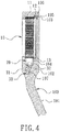
- FIG. 4 is a longitudinal sectional view in accordance with the first embodiment of the present invention.
- the present invention discloses a reversible ratchet wrench without a switch knob.
- the reversible ratchet wrench comprises a wrench body 100.
- the wrench body 100 has a handle portion 101.
- One end of the handle portion 101 is connected with a head portion 102.
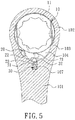
- the head portion 102 has an accommodation trough 103 and a detent trough 104 communicating with the accommodation trough 103.
- the accommodation trough 104 may be in a circular shape, an elliptical shape, or a non-circular shape.
- the accommodation trough 103 is elliptical in shape.
- the accommodation trough 103 is circumferentially formed with a first annular groove 105.
- the first annular groove 105 is provided with a positioning snap ring 106.
- the detent trough 104 is a crescent-shaped trough.
- the ratchet trough 104 is provided with a blind hole 107 in the direction of the handle portion 101.
- a ratchet wheel 10 is positioned in the accommodation trough 103 by the positioning snap ring 106.
- the outer peripheral surface of the ratchet wheel 10 is provided with a plurality of drive teeth 11.
- the ratchet wheel 10 is circumferentially formed with a second annular groove 12.
- the accommodation trough 103 is provided with a C-shaped buckle 13 corresponding to the second annular groove 12.
- the ratchet wheel 10 is displaceable in the accommodation trough 103 toward the handle portion 101 to form a first position and a second position.
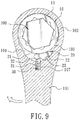
- the ratchet wheel 10 is normally located at the first position (as shown in FIG. 5 ). When the ratchet wheel 10 is located at the second position (as shown in FIG. 6 ), the ratchet wheel 10 is displaced toward the handle portion 101.
- FIG. 5 is a lateral sectional view in accordance with the first embodiment of the present invention.
- a detent 20 is disposed in the detent trough 104.
- One side of the detent 20, facing the ratchet wheel 10, is provided with a toothed surface 21.
- the toothed surface 21 is provided with a plurality of detent teeth.
- the detent teeth are configured to mesh with the drive teeth 11.
- Another side of the detent 20 is provided with a limit surface 22. Left and right sides of the limit surface 22 are formed with push portions 23, respectively. In this embodiment, the push portions 23 each have a concave shape.
- An elastic member 30 is disposed in the blind hole 107.
- the elastic member 30 is pressed against the limit surface 22.
- the elastic member 30 includes a spring 31 and a steel ball 32.
- the spring 31 is fitted with the ball 32, and the ball 32 is pressed against the limit surface 22.
- the ratchet wheel 10 is at the first position, the elastic member 30 is pressed against one of the push portions 23 of the limit surface 22.
- the ratchet wheel 10 drives the detent 20 to compress the elastic element 30.
- the ratchet wheel 10 when in use, the ratchet wheel 10 is fitted on a bolt 200, and then the handle portion 101 is turned toward the left or the right to fasten the bolt 200 tightly.
- the detent 20 since the detent 20 abuts against the left wall of the detent trough 104, when the handle portion 101 is tuned toward the right, the ratchet wheel 10 will rotate and fasten the bolt 200.
- the handle portion 101 is tuned toward the left, the ratchet wheel 10 will be idle.
- the handle portion 101 is grasped and pushed against the bolt 200 in the direction of the head portion 102. Since the bolt 200 is in an immovable state, and the ratchet wheel 10 is circular in shape but the accommodation trough 103 is a non-circular trough so that the ratchet wheel 10 is displaceable in the accommodation trough 103 in the direction of the handle portion 102.
- the ratchet wheel 10 drives the detent 20 to compress the elastic member 30.
- the user turns the handle portion 101, enabling the ratchet wheel 10 to move the detent 20 to the left or the right.
- the ratchet wheel 10 drives the detent 20 to the right, so that the elastic member 30 abuts against the other push portion 23 of the limit surface 22, and then the ratchet wheel 10 is returned to the first position.
- the handle portion 101 is tuned toward the left, the ratchet wheel 10 will rotate and fasten the bolt 200.
- the handle portion 101 is tuned toward the right, the ratchet wheel 10 will be idle.
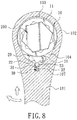
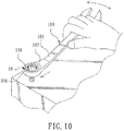
- FIG. 11 is a front view in accordance with the first embodiment of the present invention, showing the shielding effect of the C-shaped buckle.
- the accommodation trough 103 is a non-circular trough, a gap is formed between the accommodation trough 103 and the ratchet wheel 10, resulting in a poor appearance.
- the ratchet wheel 10 is circumferentially formed with the second groove 12 (see FIG. 3 ) and the accommodation trough 103 is provided with the C-shaped buckle 13 corresponding to the second annular groove 12, so that the C-shaped buckle 13 is adapted to block the gap so as to improve the appearance.
- FIG. 12 is a sectional view in accordance with a second embodiment of the present invention.
- the second embodiment is substantially similar to the first embodiment with the exceptions described hereinafter.
- the elastic member 30 is a spring 31, and the push portion 23 of the detent 20 is less concave to facilitate the spring 31 to hold against the detent 20 to achieve a simplified component and to reduce the cost of production.
- FIG. 13 is a sectional view in accordance with a third embodiment of the present invention.
- the difference between the third embodiment and the first embodiment is that the steel ball 32 has a cylindrical shape.
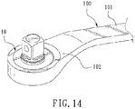
- FIG. 14 is a sectional view in accordance with a fourth embodiment of the present invention.
- the difference between the fourth embodiment and the first embodiment is that the wrench body 100 is an H-shaped ratchet wrench.
- FIG. 15 is a sectional view in accordance with a fifth embodiment of the present invention.
- the fifth embodiment is substantially similar to the first embodiment with the exceptions described hereinafter.
- the head portion 102 is further provided with a detachable outer cover 14.
- the outer cover 14 is configured to cover the accommodation trough 103 to facilitate replacement of the parts.
Landscapes
- Engineering & Computer Science (AREA)
- Mechanical Engineering (AREA)
- Details Of Spanners, Wrenches, And Screw Drivers And Accessories (AREA)
Claims (9)
- Umschaltratschenschlüssel ohne Umschaltknopf, der einen Schlüsselkörper umfasst, wobei der Schlüsselkörper einen Griffabschnitt aufweist, wobei ein Ende des Griffabschnitts mit einem Kopfabschnitt verbunden ist, gekennzeichnet durch:der Kopfabschnitt weist eine Aufnahmemulde (103) und eine Sperrstückmulde (104), die mit der Aufnahmemulde in Verbindung steht, auf, wobei die Ratschenmulde mit einem Blindloch in der Richtung des Griffabschnitts versehen ist;ein Ratschenrad (10), das in der Aufnahmemulde aufgenommen ist, wobei eine Außenumfangsoberfläche des Ratschenrads mit einer Mehrzahl von Antriebszähnen (11) versehen ist, wobei das Ratschenrad in der Aufnahmemulde in der Richtung des Griffabschnitts zur Bildung einer ersten Position und einer zweiten Position verschiebbar ist, wobei sich das Ratschenrad normalerweise an der ersten Position befindet, wobei, wenn sich das Ratschenrad an der zweiten Position befindet, das Ratschenrad in der Richtung des Griffabschnitts verschoben ist;ein Sperrstück (20), das in der Sperrstückmulde angeordnet ist, wobei eine Seite des Sperrstücks, die auf das Ratschenrad gerichtet ist, mit einer gezahnten Oberfläche versehen ist, wobei die gezahnte Oberfläche mit einer Mehrzahl von Sperrzähnen versehen ist, wobei die Sperrzähne zum Kämmen mit den Antriebszähnen ausgebildet sind, wobei die andere Seite des Sperrstücks mit einer Begrenzungsoberfläche (22) versehen ist, wobei die linke und die rechte Seite der Begrenzungsoberfläche jeweils mit Schiebeabschnitten (23) ausgebildet sind;ein elastisches Element, das in dem Blindloch angeordnet ist, wobei das elastische Element gegen die Begrenzungsoberfläche gedrückt wird, wobei, wenn sich das Ratschenrad an der ersten Position befindet, das elastische Element gegen einen der Schiebeabschnitte der Begrenzungsoberfläche gedrückt wird, wobei, wenn sich das Ratschenrad an der zweiten Position befindet, das Ratschenrad das Sperrstück so antreibt, dass es das elastische Element zusammendrückt;wobei für einen Umschaltvorgang das Ratschenrad zu der zweiten Position verschoben wird, so dass es das elastische Element zusammendrückt, und dann das Ratschenrad gedreht wird, so dass das Sperrstück zum Bewegen nach links oder rechts angetrieben wird, so dass das elastische Element gegen den anderen Schiebeabschnitt der Begrenzungsoberfläche gedrückt wird, wodurch der Umschaltvorgang abgeschlossen wird.
- Umschaltratschenschlüssel nach Anspruch 1, bei dem die Aufnahmemulde eine nicht-kreisförmige Mulde ist und die Sperrstückmulde eine halbmondförmige Mulde ist.
- Umschaltratschenschlüssel nach Anspruch 1, bei dem das elastische Element eine Feder ist.
- Umschaltratschenschlüssel nach Anspruch 1, bei dem das elastische Element eine Feder und eine Stahlkugel umfasst, wobei die Feder mit der Kugel versehen ist und die Kugel gegen die Begrenzungsoberfläche gedrückt wird.
- Umschaltratschenschlüssel nach Anspruch 4, bei dem die Stahlkugel eine zylindrische Form aufweist.
- Umschaltratschenschlüssel nach Anspruch 1, bei dem die Aufnahmemulde in der Umfangsrichtung mit einer ersten ringförmigen Rille ausgebildet ist, wobei die erste ringförmige Rille mit einem Positionierungsseegerring versehen ist und der Positionierungsseegerring das Ratschenrad in der Aufnahmemulde hält.
- Umschaltratschenschlüssel nach Anspruch 1, bei dem das Ratschenrad in der Umfangsrichtung mit einer zweiten ringförmigen Rille ausgebildet ist und die Aufnahmemulde mit einem C-förmigen Verriegelungselement versehen ist, das der zweiten ringförmigen Rille entspricht.
- Umschaltratschenschlüssel nach Anspruch 1, bei dem der Kopfabschnitt mit einer äußeren Abdeckung versehen ist und die äußere Abdeckung zum Abdecken der Aufnahmemulde ausgebildet ist.
- Umschaltratschenschlüssel nach Anspruch 1, bei dem die Schiebeabschnitte jeweils eine konkave Form aufweisen.
Applications Claiming Priority (1)
| Application Number | Priority Date | Filing Date | Title |
|---|---|---|---|
| TW106112163A TWI608907B (zh) | 2017-04-12 | 2017-04-12 | Reversible ratchet wrench |
Publications (2)
| Publication Number | Publication Date |
|---|---|
| EP3388198A1 EP3388198A1 (de) | 2018-10-17 |
| EP3388198B1 true EP3388198B1 (de) | 2019-06-05 |
Family
ID=61054245
Family Applications (1)
| Application Number | Title | Priority Date | Filing Date |
|---|---|---|---|
| EP18153670.7A Active EP3388198B1 (de) | 2017-04-12 | 2018-01-26 | Umkehrbarer ratschenschlüssel ohne schaltknopf |
Country Status (4)
| Country | Link |
|---|---|
| US (1) | US10279458B2 (de) |
| EP (1) | EP3388198B1 (de) |
| JP (1) | JP6646096B2 (de) |
| TW (1) | TWI608907B (de) |
Families Citing this family (7)
| Publication number | Priority date | Publication date | Assignee | Title |
|---|---|---|---|---|
| TWI703014B (zh) * | 2019-09-05 | 2020-09-01 | 華偉工具有限公司 | 高強度扳手 |
| US11331774B2 (en) * | 2019-09-30 | 2022-05-17 | Harbor Freight Tools Usa, Inc. | Ratchet tool with improved pawl |
| TWI722884B (zh) * | 2020-04-29 | 2021-03-21 | 華偉工具有限公司 | 棘輪座、棘輪工具頭及雙向棘輪手工具 |
| USD1116673S1 (en) * | 2023-01-14 | 2026-03-10 | Harbor Freight Tools Usa, Inc. | Rachet sleeve |
| US20250229387A1 (en) * | 2024-01-16 | 2025-07-17 | Harbor Freight Tools Usa, Inc. | Ratchet Tool Including Pawl with Biasing Effect |
| USD1122706S1 (en) * | 2024-02-16 | 2026-04-21 | Stanley Black & Decker Inc. | Gear for a hand tool |
| USD1123549S1 (en) * | 2024-02-16 | 2026-04-28 | Stanley Black & Decker, Inc. | Gear for a hand tool |
Family Cites Families (33)
| Publication number | Priority date | Publication date | Assignee | Title |
|---|---|---|---|---|
| US4270417A (en) * | 1980-03-17 | 1981-06-02 | Joseph Tesoro | Two-way ratchet wrench |
| US5709137A (en) * | 1995-04-24 | 1998-01-20 | Blacklock; Gordon D. | Torque clutched reversible ratchet wrench |
| US5842391A (en) * | 1997-03-07 | 1998-12-01 | Chaconas; Peter Constantine | Wrench with ratcheting action |
| US6134990A (en) * | 1999-08-05 | 2000-10-24 | Hand Tool Design Corporation | Ratcheting tool with improved gear wheel/pawl engagement |
| US6745647B2 (en) * | 2000-11-29 | 2004-06-08 | Mei-Chen Wang | Wrench having a universal-joint ratchet wheel |
| US6807882B2 (en) * | 2001-05-07 | 2004-10-26 | Bobby Hu | Wrench with a simplified structure |
| US6415691B1 (en) * | 2001-08-29 | 2002-07-09 | Mu Lin Chen | Ratchet wrench structure having a high torsion driving action along dual directions |
| US6408722B1 (en) * | 2001-09-20 | 2002-06-25 | Yu-Tang Chen | Ratchet wheel mounting arrangement for wrench |
| TW506308U (en) * | 2002-02-08 | 2002-10-11 | Hou-Fei Hu | Improved structure for ratchet wrench |
| US20040216565A1 (en) * | 2002-11-11 | 2004-11-04 | Terence Chen | Pawl having at least two supporting protrusions for contacting inside of recess of ratchet wrench |
| US6874391B2 (en) * | 2003-07-01 | 2005-04-05 | One-way ratchet wrench | |
| US7051623B2 (en) * | 2003-07-28 | 2006-05-30 | Easco Hand Tools, Inc. | Pawl-less ratchet wrench |
| US7334504B2 (en) * | 2003-08-25 | 2008-02-26 | Lin-Lang Liu | High torsional force structure of ratchet device |
| US20080034926A1 (en) * | 2006-08-10 | 2008-02-14 | Chaconas Peter C | Bi-directional pawl-less wrench |
| US7444903B1 (en) * | 2007-10-30 | 2008-11-04 | Hua Pan Co., Ltd. | Ratchet wrench having reinforced strength |
| US7823484B1 (en) * | 2008-09-15 | 2010-11-02 | Wei-Chu Chen | Reversible ratchet wrench whose operation directions are changed easily and quickly |
| CN201361837Y (zh) * | 2009-01-12 | 2009-12-16 | 王宗孚 | 移爪棘轮机构 |
| TWM361409U (en) * | 2009-03-31 | 2009-07-21 | Jian-Yue Lin | Bi-directional ratchet wrench |
| TW201036764A (en) * | 2009-04-03 | 2010-10-16 | Yuan-Jin Ji | Structure of twisting-free bi-directional switch-controlled ratchet wrench |
| US20110113930A1 (en) * | 2009-11-16 | 2011-05-19 | Ceo Tool Co., Ltd. | Open end ratchet wrench |
| US8245602B2 (en) * | 2010-01-07 | 2012-08-21 | Meng Tsung Chan | Ratchet wrench |
| US8943928B2 (en) * | 2011-02-14 | 2015-02-03 | Zhejiang Yiyang Tool Manufacture Co., Ltd. | Ratchet wheel wrench |
| TWM449061U (zh) * | 2012-08-10 | 2013-03-21 | xiu-li Wei | 具套筒夾持裝置之穿透式棘輪扳手 |
| TWM456259U (zh) * | 2012-11-30 | 2013-07-01 | Zuan-Cang Li | 棘輪扳手之制齒結構 |
| US9821441B2 (en) * | 2014-02-13 | 2017-11-21 | Yi-Fu Chen | Ratchet wrench |
| US20150224631A1 (en) * | 2014-02-13 | 2015-08-13 | Yi-Fu Chen | Ratchet wrench |
| US9327389B2 (en) * | 2014-02-25 | 2016-05-03 | Yi-Fu Chen | Ratchet wrench |
| US20160167203A1 (en) * | 2014-12-16 | 2016-06-16 | Chia-Yu Chen | Ratchet wrench able to enhance positioning effect of ratchet |
| TWI598192B (zh) * | 2015-03-30 | 2017-09-11 | Yan-Ru Ji | Ratchet wrench direction switch structure |
| TWM511925U (zh) * | 2015-03-30 | 2015-11-11 | Yan-Ru Ji | 棘輪扳手方向切換控制構造 |
| US10682744B2 (en) * | 2015-05-15 | 2020-06-16 | Ming Liang Zhang | Ratchet wrench providing combined functions of ordinary ratchet wrenches |
| TWM509704U (zh) * | 2015-07-10 | 2015-10-01 | Jun-Wen Liao | 棘輪扳手結構 |
| TWI547350B (zh) * | 2015-11-18 | 2016-09-01 | Jia-You Chen | Ratchet wrench structure |
-
2017
- 2017-04-12 TW TW106112163A patent/TWI608907B/zh active
- 2017-05-04 US US15/586,614 patent/US10279458B2/en active Active
-
2018
- 2018-01-26 EP EP18153670.7A patent/EP3388198B1/de active Active
- 2018-04-11 JP JP2018076364A patent/JP6646096B2/ja not_active Expired - Fee Related
Non-Patent Citations (1)
| Title |
|---|
| None * |
Also Published As
| Publication number | Publication date |
|---|---|
| JP2018176418A (ja) | 2018-11-15 |
| US10279458B2 (en) | 2019-05-07 |
| TWI608907B (zh) | 2017-12-21 |
| US20180297177A1 (en) | 2018-10-18 |
| JP6646096B2 (ja) | 2020-02-14 |
| EP3388198A1 (de) | 2018-10-17 |
| TW201836772A (zh) | 2018-10-16 |
Similar Documents
| Publication | Publication Date | Title |
|---|---|---|
| EP3388198B1 (de) | Umkehrbarer ratschenschlüssel ohne schaltknopf | |
| US5230262A (en) | Ratchet wrench | |
| US4290328A (en) | Ratchet handle | |
| US5174176A (en) | Reversible rachet wrench with integrated dual pawl and spring and cam unit | |
| US9649751B2 (en) | Reversible ratchet wrench with a smaller rotational angle | |
| US8522651B2 (en) | Ratcheting driver mechanism | |
| US8650991B2 (en) | Ratchet wrench | |
| US20070256525A1 (en) | Rotary wrench structure | |
| US8931375B2 (en) | Ratchet device | |
| US8943929B2 (en) | Torsion adjustment structure of ratchet wrench | |
| US20040107803A1 (en) | Quick rotation wrench having an angle adjustment structure | |
| US20120031239A1 (en) | Retractable screwdriver | |
| TWM556200U (zh) | 鎖固型扭力扳手 | |
| US6513409B1 (en) | Ratchet wrench structure | |
| US20170197298A1 (en) | Stepless wrench with toothless drive | |
| US9333628B2 (en) | Driving end of tool | |
| EP2543904A2 (de) | Kupplung, die zur Kraftübertragung in einer ausgewählten von zwei Richtungen in der Lage ist | |
| US6732613B2 (en) | Screwdriver with changeable operation modes | |
| US20110162489A1 (en) | Ratchet Wrench | |
| US20150224631A1 (en) | Ratchet wrench | |
| US7162937B1 (en) | Positioning device for a two-way ratchet tool | |
| US11491614B2 (en) | Ratchet wrench allowing easy change of rotation direction | |
| US9409284B2 (en) | Ratchet handle | |
| US11117244B2 (en) | Ratchet wrench | |
| TWI226273B (en) | Reversible driven rotating wrench |
Legal Events
| Date | Code | Title | Description |
|---|---|---|---|
| PUAI | Public reference made under article 153(3) epc to a published international application that has entered the european phase |
Free format text: ORIGINAL CODE: 0009012 |
|
| STAA | Information on the status of an ep patent application or granted ep patent |
Free format text: STATUS: THE APPLICATION HAS BEEN PUBLISHED |
|
| STAA | Information on the status of an ep patent application or granted ep patent |
Free format text: STATUS: REQUEST FOR EXAMINATION WAS MADE |
|
| AK | Designated contracting states |
Kind code of ref document: A1 Designated state(s): AL AT BE BG CH CY CZ DE DK EE ES FI FR GB GR HR HU IE IS IT LI LT LU LV MC MK MT NL NO PL PT RO RS SE SI SK SM TR |
|
| AX | Request for extension of the european patent |
Extension state: BA ME |
|
| 17P | Request for examination filed |
Effective date: 20181001 |
|
| RBV | Designated contracting states (corrected) |
Designated state(s): AL AT BE BG CH CY CZ DE DK EE ES FI FR GB GR HR HU IE IS IT LI LT LU LV MC MK MT NL NO PL PT RO RS SE SI SK SM TR |
|
| GRAP | Despatch of communication of intention to grant a patent |
Free format text: ORIGINAL CODE: EPIDOSNIGR1 |
|
| STAA | Information on the status of an ep patent application or granted ep patent |
Free format text: STATUS: GRANT OF PATENT IS INTENDED |
|
| RIC1 | Information provided on ipc code assigned before grant |
Ipc: B25B 13/46 20060101AFI20190129BHEP |
|
| INTG | Intention to grant announced |
Effective date: 20190218 |
|
| GRAS | Grant fee paid |
Free format text: ORIGINAL CODE: EPIDOSNIGR3 |
|
| GRAA | (expected) grant |
Free format text: ORIGINAL CODE: 0009210 |
|
| STAA | Information on the status of an ep patent application or granted ep patent |
Free format text: STATUS: THE PATENT HAS BEEN GRANTED |
|
| AK | Designated contracting states |
Kind code of ref document: B1 Designated state(s): AL AT BE BG CH CY CZ DE DK EE ES FI FR GB GR HR HU IE IS IT LI LT LU LV MC MK MT NL NO PL PT RO RS SE SI SK SM TR |
|
| REG | Reference to a national code |
Ref country code: GB Ref legal event code: FG4D |
|
| REG | Reference to a national code |
Ref country code: CH Ref legal event code: EP |
|
| REG | Reference to a national code |
Ref country code: AT Ref legal event code: REF Ref document number: 1139520 Country of ref document: AT Kind code of ref document: T Effective date: 20190615 |
|
| REG | Reference to a national code |
Ref country code: DE Ref legal event code: R096 Ref document number: 602018000111 Country of ref document: DE |
|
| REG | Reference to a national code |
Ref country code: IE Ref legal event code: FG4D |
|
| REG | Reference to a national code |
Ref country code: NL Ref legal event code: MP Effective date: 20190605 |
|
| REG | Reference to a national code |
Ref country code: LT Ref legal event code: MG4D |
|
| PG25 | Lapsed in a contracting state [announced via postgrant information from national office to epo] |
Ref country code: HR Free format text: LAPSE BECAUSE OF FAILURE TO SUBMIT A TRANSLATION OF THE DESCRIPTION OR TO PAY THE FEE WITHIN THE PRESCRIBED TIME-LIMIT Effective date: 20190605 Ref country code: SE Free format text: LAPSE BECAUSE OF FAILURE TO SUBMIT A TRANSLATION OF THE DESCRIPTION OR TO PAY THE FEE WITHIN THE PRESCRIBED TIME-LIMIT Effective date: 20190605 Ref country code: AL Free format text: LAPSE BECAUSE OF FAILURE TO SUBMIT A TRANSLATION OF THE DESCRIPTION OR TO PAY THE FEE WITHIN THE PRESCRIBED TIME-LIMIT Effective date: 20190605 Ref country code: FI Free format text: LAPSE BECAUSE OF FAILURE TO SUBMIT A TRANSLATION OF THE DESCRIPTION OR TO PAY THE FEE WITHIN THE PRESCRIBED TIME-LIMIT Effective date: 20190605 Ref country code: NO Free format text: LAPSE BECAUSE OF FAILURE TO SUBMIT A TRANSLATION OF THE DESCRIPTION OR TO PAY THE FEE WITHIN THE PRESCRIBED TIME-LIMIT Effective date: 20190905 Ref country code: ES Free format text: LAPSE BECAUSE OF FAILURE TO SUBMIT A TRANSLATION OF THE DESCRIPTION OR TO PAY THE FEE WITHIN THE PRESCRIBED TIME-LIMIT Effective date: 20190605 Ref country code: LT Free format text: LAPSE BECAUSE OF FAILURE TO SUBMIT A TRANSLATION OF THE DESCRIPTION OR TO PAY THE FEE WITHIN THE PRESCRIBED TIME-LIMIT Effective date: 20190605 |
|
| PG25 | Lapsed in a contracting state [announced via postgrant information from national office to epo] |
Ref country code: GR Free format text: LAPSE BECAUSE OF FAILURE TO SUBMIT A TRANSLATION OF THE DESCRIPTION OR TO PAY THE FEE WITHIN THE PRESCRIBED TIME-LIMIT Effective date: 20190906 Ref country code: BG Free format text: LAPSE BECAUSE OF FAILURE TO SUBMIT A TRANSLATION OF THE DESCRIPTION OR TO PAY THE FEE WITHIN THE PRESCRIBED TIME-LIMIT Effective date: 20190905 Ref country code: RS Free format text: LAPSE BECAUSE OF FAILURE TO SUBMIT A TRANSLATION OF THE DESCRIPTION OR TO PAY THE FEE WITHIN THE PRESCRIBED TIME-LIMIT Effective date: 20190605 Ref country code: LV Free format text: LAPSE BECAUSE OF FAILURE TO SUBMIT A TRANSLATION OF THE DESCRIPTION OR TO PAY THE FEE WITHIN THE PRESCRIBED TIME-LIMIT Effective date: 20190605 |
|
| REG | Reference to a national code |
Ref country code: AT Ref legal event code: MK05 Ref document number: 1139520 Country of ref document: AT Kind code of ref document: T Effective date: 20190605 |
|
| PG25 | Lapsed in a contracting state [announced via postgrant information from national office to epo] |
Ref country code: EE Free format text: LAPSE BECAUSE OF FAILURE TO SUBMIT A TRANSLATION OF THE DESCRIPTION OR TO PAY THE FEE WITHIN THE PRESCRIBED TIME-LIMIT Effective date: 20190605 Ref country code: NL Free format text: LAPSE BECAUSE OF FAILURE TO SUBMIT A TRANSLATION OF THE DESCRIPTION OR TO PAY THE FEE WITHIN THE PRESCRIBED TIME-LIMIT Effective date: 20190605 Ref country code: RO Free format text: LAPSE BECAUSE OF FAILURE TO SUBMIT A TRANSLATION OF THE DESCRIPTION OR TO PAY THE FEE WITHIN THE PRESCRIBED TIME-LIMIT Effective date: 20190605 Ref country code: AT Free format text: LAPSE BECAUSE OF FAILURE TO SUBMIT A TRANSLATION OF THE DESCRIPTION OR TO PAY THE FEE WITHIN THE PRESCRIBED TIME-LIMIT Effective date: 20190605 Ref country code: CZ Free format text: LAPSE BECAUSE OF FAILURE TO SUBMIT A TRANSLATION OF THE DESCRIPTION OR TO PAY THE FEE WITHIN THE PRESCRIBED TIME-LIMIT Effective date: 20190605 Ref country code: SK Free format text: LAPSE BECAUSE OF FAILURE TO SUBMIT A TRANSLATION OF THE DESCRIPTION OR TO PAY THE FEE WITHIN THE PRESCRIBED TIME-LIMIT Effective date: 20190605 Ref country code: PT Free format text: LAPSE BECAUSE OF FAILURE TO SUBMIT A TRANSLATION OF THE DESCRIPTION OR TO PAY THE FEE WITHIN THE PRESCRIBED TIME-LIMIT Effective date: 20191007 |
|
| PG25 | Lapsed in a contracting state [announced via postgrant information from national office to epo] |
Ref country code: IS Free format text: LAPSE BECAUSE OF FAILURE TO SUBMIT A TRANSLATION OF THE DESCRIPTION OR TO PAY THE FEE WITHIN THE PRESCRIBED TIME-LIMIT Effective date: 20191005 Ref country code: SM Free format text: LAPSE BECAUSE OF FAILURE TO SUBMIT A TRANSLATION OF THE DESCRIPTION OR TO PAY THE FEE WITHIN THE PRESCRIBED TIME-LIMIT Effective date: 20190605 Ref country code: IT Free format text: LAPSE BECAUSE OF FAILURE TO SUBMIT A TRANSLATION OF THE DESCRIPTION OR TO PAY THE FEE WITHIN THE PRESCRIBED TIME-LIMIT Effective date: 20190605 |
|
| REG | Reference to a national code |
Ref country code: DE Ref legal event code: R097 Ref document number: 602018000111 Country of ref document: DE |
|
| PG25 | Lapsed in a contracting state [announced via postgrant information from national office to epo] |
Ref country code: TR Free format text: LAPSE BECAUSE OF FAILURE TO SUBMIT A TRANSLATION OF THE DESCRIPTION OR TO PAY THE FEE WITHIN THE PRESCRIBED TIME-LIMIT Effective date: 20190605 |
|
| PLBE | No opposition filed within time limit |
Free format text: ORIGINAL CODE: 0009261 |
|
| STAA | Information on the status of an ep patent application or granted ep patent |
Free format text: STATUS: NO OPPOSITION FILED WITHIN TIME LIMIT |
|
| PG25 | Lapsed in a contracting state [announced via postgrant information from national office to epo] |
Ref country code: DK Free format text: LAPSE BECAUSE OF FAILURE TO SUBMIT A TRANSLATION OF THE DESCRIPTION OR TO PAY THE FEE WITHIN THE PRESCRIBED TIME-LIMIT Effective date: 20190605 Ref country code: PL Free format text: LAPSE BECAUSE OF FAILURE TO SUBMIT A TRANSLATION OF THE DESCRIPTION OR TO PAY THE FEE WITHIN THE PRESCRIBED TIME-LIMIT Effective date: 20190605 |
|
| 26N | No opposition filed |
Effective date: 20200306 |
|
| REG | Reference to a national code |
Ref country code: DE Ref legal event code: R119 Ref document number: 602018000111 Country of ref document: DE |
|
| PG25 | Lapsed in a contracting state [announced via postgrant information from national office to epo] |
Ref country code: MC Free format text: LAPSE BECAUSE OF FAILURE TO SUBMIT A TRANSLATION OF THE DESCRIPTION OR TO PAY THE FEE WITHIN THE PRESCRIBED TIME-LIMIT Effective date: 20190605 |
|
| REG | Reference to a national code |
Ref country code: BE Ref legal event code: MM Effective date: 20200131 |
|
| PG25 | Lapsed in a contracting state [announced via postgrant information from national office to epo] |
Ref country code: FR Free format text: LAPSE BECAUSE OF NON-PAYMENT OF DUE FEES Effective date: 20200131 Ref country code: DE Free format text: LAPSE BECAUSE OF NON-PAYMENT OF DUE FEES Effective date: 20200801 Ref country code: LU Free format text: LAPSE BECAUSE OF NON-PAYMENT OF DUE FEES Effective date: 20200126 |
|
| PG25 | Lapsed in a contracting state [announced via postgrant information from national office to epo] |
Ref country code: BE Free format text: LAPSE BECAUSE OF NON-PAYMENT OF DUE FEES Effective date: 20200131 |
|
| PG25 | Lapsed in a contracting state [announced via postgrant information from national office to epo] |
Ref country code: IE Free format text: LAPSE BECAUSE OF NON-PAYMENT OF DUE FEES Effective date: 20200126 |
|
| REG | Reference to a national code |
Ref country code: CH Ref legal event code: PL |
|
| PG25 | Lapsed in a contracting state [announced via postgrant information from national office to epo] |
Ref country code: CH Free format text: LAPSE BECAUSE OF NON-PAYMENT OF DUE FEES Effective date: 20210131 Ref country code: LI Free format text: LAPSE BECAUSE OF NON-PAYMENT OF DUE FEES Effective date: 20210131 |
|
| PG25 | Lapsed in a contracting state [announced via postgrant information from national office to epo] |
Ref country code: MT Free format text: LAPSE BECAUSE OF FAILURE TO SUBMIT A TRANSLATION OF THE DESCRIPTION OR TO PAY THE FEE WITHIN THE PRESCRIBED TIME-LIMIT Effective date: 20190605 Ref country code: CY Free format text: LAPSE BECAUSE OF FAILURE TO SUBMIT A TRANSLATION OF THE DESCRIPTION OR TO PAY THE FEE WITHIN THE PRESCRIBED TIME-LIMIT Effective date: 20190605 |
|
| PG25 | Lapsed in a contracting state [announced via postgrant information from national office to epo] |
Ref country code: MK Free format text: LAPSE BECAUSE OF FAILURE TO SUBMIT A TRANSLATION OF THE DESCRIPTION OR TO PAY THE FEE WITHIN THE PRESCRIBED TIME-LIMIT Effective date: 20190605 |
|
| GBPC | Gb: european patent ceased through non-payment of renewal fee |
Effective date: 20220126 |
|
| PG25 | Lapsed in a contracting state [announced via postgrant information from national office to epo] |
Ref country code: GB Free format text: LAPSE BECAUSE OF NON-PAYMENT OF DUE FEES Effective date: 20220126 |
|
| PG25 | Lapsed in a contracting state [announced via postgrant information from national office to epo] |
Ref country code: SI Free format text: LAPSE BECAUSE OF FAILURE TO SUBMIT A TRANSLATION OF THE DESCRIPTION OR TO PAY THE FEE WITHIN THE PRESCRIBED TIME-LIMIT Effective date: 20190605 |