EP3388176A1 - Circular sawing machine in which wobble of circular saw blade can be suppressed - Google Patents
Circular sawing machine in which wobble of circular saw blade can be suppressed Download PDFInfo
- Publication number
- EP3388176A1 EP3388176A1 EP16872878.0A EP16872878A EP3388176A1 EP 3388176 A1 EP3388176 A1 EP 3388176A1 EP 16872878 A EP16872878 A EP 16872878A EP 3388176 A1 EP3388176 A1 EP 3388176A1
- Authority
- EP
- European Patent Office
- Prior art keywords
- saw blade
- cutting
- circular saw
- movable
- processing head
- Prior art date
- Legal status (The legal status is an assumption and is not a legal conclusion. Google has not performed a legal analysis and makes no representation as to the accuracy of the status listed.)
- Granted
Links
Images





Classifications
-
- B—PERFORMING OPERATIONS; TRANSPORTING
- B23—MACHINE TOOLS; METAL-WORKING NOT OTHERWISE PROVIDED FOR
- B23D—PLANING; SLOTTING; SHEARING; BROACHING; SAWING; FILING; SCRAPING; LIKE OPERATIONS FOR WORKING METAL BY REMOVING MATERIAL, NOT OTHERWISE PROVIDED FOR
- B23D45/00—Sawing machines or sawing devices with circular saw blades or with friction saw discs
- B23D45/02—Sawing machines or sawing devices with circular saw blades or with friction saw discs with a circular saw blade or the stock mounted on a carriage
-
- B—PERFORMING OPERATIONS; TRANSPORTING
- B23—MACHINE TOOLS; METAL-WORKING NOT OTHERWISE PROVIDED FOR
- B23D—PLANING; SLOTTING; SHEARING; BROACHING; SAWING; FILING; SCRAPING; LIKE OPERATIONS FOR WORKING METAL BY REMOVING MATERIAL, NOT OTHERWISE PROVIDED FOR
- B23D47/00—Sawing machines or sawing devices working with circular saw blades, characterised only by constructional features of particular parts
-
- B—PERFORMING OPERATIONS; TRANSPORTING
- B23—MACHINE TOOLS; METAL-WORKING NOT OTHERWISE PROVIDED FOR
- B23D—PLANING; SLOTTING; SHEARING; BROACHING; SAWING; FILING; SCRAPING; LIKE OPERATIONS FOR WORKING METAL BY REMOVING MATERIAL, NOT OTHERWISE PROVIDED FOR
- B23D47/00—Sawing machines or sawing devices working with circular saw blades, characterised only by constructional features of particular parts
- B23D47/005—Vibration-damping
-
- B—PERFORMING OPERATIONS; TRANSPORTING
- B23—MACHINE TOOLS; METAL-WORKING NOT OTHERWISE PROVIDED FOR
- B23D—PLANING; SLOTTING; SHEARING; BROACHING; SAWING; FILING; SCRAPING; LIKE OPERATIONS FOR WORKING METAL BY REMOVING MATERIAL, NOT OTHERWISE PROVIDED FOR
- B23D47/00—Sawing machines or sawing devices working with circular saw blades, characterised only by constructional features of particular parts
- B23D47/08—Sawing machines or sawing devices working with circular saw blades, characterised only by constructional features of particular parts of devices for bringing the circular saw blade to the workpiece or removing same therefrom
-
- B—PERFORMING OPERATIONS; TRANSPORTING
- B27—WORKING OR PRESERVING WOOD OR SIMILAR MATERIAL; NAILING OR STAPLING MACHINES IN GENERAL
- B27B—SAWS FOR WOOD OR SIMILAR MATERIAL; COMPONENTS OR ACCESSORIES THEREFOR
- B27B5/00—Sawing machines working with circular or cylindrical saw blades; Components or equipment therefor
- B27B5/29—Details; Component parts; Accessories
- B27B5/30—Details; Component parts; Accessories for mounting or securing saw blades or saw spindles
-
- B—PERFORMING OPERATIONS; TRANSPORTING
- B23—MACHINE TOOLS; METAL-WORKING NOT OTHERWISE PROVIDED FOR
- B23D—PLANING; SLOTTING; SHEARING; BROACHING; SAWING; FILING; SCRAPING; LIKE OPERATIONS FOR WORKING METAL BY REMOVING MATERIAL, NOT OTHERWISE PROVIDED FOR
- B23D45/00—Sawing machines or sawing devices with circular saw blades or with friction saw discs
- B23D45/02—Sawing machines or sawing devices with circular saw blades or with friction saw discs with a circular saw blade or the stock mounted on a carriage
- B23D45/021—Sawing machines or sawing devices with circular saw blades or with friction saw discs with a circular saw blade or the stock mounted on a carriage with the saw blade mounted on a carriage
-
- B—PERFORMING OPERATIONS; TRANSPORTING
- B23—MACHINE TOOLS; METAL-WORKING NOT OTHERWISE PROVIDED FOR
- B23D—PLANING; SLOTTING; SHEARING; BROACHING; SAWING; FILING; SCRAPING; LIKE OPERATIONS FOR WORKING METAL BY REMOVING MATERIAL, NOT OTHERWISE PROVIDED FOR
- B23D47/00—Sawing machines or sawing devices working with circular saw blades, characterised only by constructional features of particular parts
- B23D47/02—Sawing machines or sawing devices working with circular saw blades, characterised only by constructional features of particular parts of frames; of guiding arrangements for work-table or saw-carrier
- B23D47/025—Sawing machines or sawing devices working with circular saw blades, characterised only by constructional features of particular parts of frames; of guiding arrangements for work-table or saw-carrier of tables
Definitions
- the present invention relates to a circular saw machine for carrying out a cutting processing with respect to a portion to be cut of a workpiece.
- the conventional circular saw machine has a processing head having a circular saw blade capable of rotating, and this processing head is made to be capable of moving in a cutting direction for imparting a cut to a workpiece and its opposite direction.
- a region positioned on a cutting direction side in the circular saw blade is made to be a cutting region in which a cutting effect is effectuated.
- the processing head is equipped with a pair of fixed saw blade guide sets for guiding to pinch a body part of the circular saw blade on both sides of the cutting region in the circular saw blade.
- the pair of fixed saw blade guide sets are separated in a direction orthogonal to the cutting direction, and usually, an interval in said orthogonal direction of the pair of fixed saw blade guide sets is set to be an interval in accordance with a largest width (a maximum width) of a workpiece to be a cutting target.
- Patent Document 1 Japanese Patent Application Publication No. H9-85527
- the interval in said orthogonal direction of the pair of fixed saw blade guide sets is set as described above, and in the case of carrying out the cutting processing with respect to a portion to be cut of a workpiece with a small width, a distance between the fixed saw blade guide sets and a portion to be cut of the workpiece becomes large, so that a rigidity of the cutting region in the circular saw blade cannot be secured sufficiently. For this reason, a cutting-bending of the circular saw blade is easy to occur during the cutting processing, and there are cases where a lowering of a processing accuracy (surface accuracy) for a cutting surface of the workpiece is caused.
- the conventional circular saw machine has a problem in that it is difficult to suppress a cutting-bending of the circular saw blade during the cutting processing, and improve a processing accuracy for a cutting surface of the workpiece, regardless of a size of a width of the workpiece.
- the present invention has an object of providing a circular saw machine comprised of a new configuration, which can resolve the problem described above.
- a circular saw machine comprising: a processing head capable of moving in a cutting direction for imparting a cut to a workpiece and its opposite direction, and having a circular saw blade capable of rotating; and a movable saw blade guide set provided to be movable in said cutting direction and said opposite direction (a diameter direction of said circular saw blade) on said processing head, for guiding to pinch a body part of said circular saw blade on a diameter direction inner side (a diameter direction inner side of said circular saw blade) of a cutting region in which a cutting effect in said circular saw blade is effectuated, said movable saw blade guide set being configured to move relatively with respect to said processing head in said opposite direction, in coordination with a movement in said cutting direction of said processing head, as a cutting into the workpiece progresses.
- said circular saw machine is further comprising a pair of fixed saw blade guide sets provided to be separated in a direction orthogonal to said cutting direction on said processing head, for guiding to pinch the body part of said circular saw blade on both sides (both sides of said orthogonal direction) of said cutting region.
- said circular saw machine is further comprising: a stopper for regulating a movement in said cutting direction of said movable saw blade guide set with respect to said processing head; and a biasing member for biasing said movable saw blade guide set into said cutting direction.
- said circular saw machine is further comprising an actuator for moving said movable saw blade guide set relatively with respect to said processing head in said cutting direction and said opposite direction.
- said circular saw machine is such that said movable saw blade guide set is divided in a direction orthogonal to said cutting direction.
- said processing head has a saw blade casing for housing said circular saw blade; said saw blade casing has a casing body, and a casing rid provided on said casing body and capable of opening or closing a front side of said casing body; and said movable saw blade guide set has: a first movable insert provided to be movable in said cutting direction and said opposite direction on an inner surface of said casing body and being capable of contacting a back surface of the body part of said circular saw blade; and a second movable insert provided to be movable in said cutting direction and said opposite direction on an inner surface of said casing rid and being capable of contacting a front surface of the body part of said circular saw blade.
- said processing head is moved in said cutting direction, in a state where said circular saw blade is rotated. Then, it is possible to impart a cut to the workpiece by said circular saw blade, and carry out a cutting processing with respect to a portion to be cut of the workpiece.
- said movable saw blade guide set guides to pinch a body part of said circular saw blade on a diameter direction inner side of said cutting region in said circular saw blade.
- said movable saw blade guide set moves relatively with respect to said processing head in said opposite direction, in coordination with a movement in said cutting direction of said processing head.
- the present invention it is possible to suppress a runout of said circular saw blade when said circular saw blade is plunging into the workpiece, regardless of a size of a width of the workpiece.
- FF indicates a front direction (conveying direction)
- FR indicates a rear direction
- L indicates a left direction
- R indicates a right direction
- U indicates an upward direction
- D indicates a downward direction, respectively.
- the circular saw machine 1 carries out the cutting processing with respect to a portion to be cut of a rod shaped workpiece W which is positioned to a cutting position in the conveying direction (front direction). Then, a configuration of the circular saw machine 1 according to the embodiment of the present invention is as follows.
- the circular saw machine 1 is equipped with a base mount (bed) 3 extended in a conveying width direction (left and right direction) orthogonal to the conveying direction, and a support frame 5 provided on a left portion of an upper surface of this base mount 3.
- the support frame 3 has an inclined surface 5f that is inclined with respect to a horizontal direction (left and right direction).
- the base mount 3 is equipped with a main body vice 7 for fixing the workpiece W with respect to the base mount 3, in an immediately upstream side (immediately upstream side in the conveying direction) of the cutting position in its upper surface (upper surface of the base mount 3).
- the main body vice 7 has a vice bed (processing table) 9 provided on the upper surface of the base mount 3 and supporting the workpiece W.
- the vice bed 9 is equipped with a fixed vice jaw 11 on a left portion of its upper surface (upper surface of the vice bed 9).
- the vice bed 9 is equipped with a movable vice jaw 13 pinching the workpiece W in cooperation with the fixed vice jaw 11, on its upper surface, and this movable vice jaw 13 is made to be movable in the conveying width direction.
- the vice bed 9 is equipped with a hydraulic cylinder for vice 15 that moves the movable vice jaw 13 in the conveying width direction.
- the base mount 3 is equipped with a conveying table (omitted to be shown in the figure) for supporting the workpiece W to be movable in the conveying direction, on its rear side (rear side of the base mount 3).
- the conveying table is equipped with a conveying vice (omitted to be shown in the figure) for conveying the workpiece W in the conveying direction, at its appropriate position (appropriate position of the conveying table).
- the support frame 5 is equipped with a plurality (only one is shown in the figure) of guide rails 17 extended in an inclined direction, on its inclined surface 5f.
- the plurality of guide rails 17 are equipped with a processing head 21 having a circular saw blade 19 that is capable of rotating, between them (between the plurality of guide rails 17).
- the circular saw blade 19 has a disk shaped body part 19b, and a plurality (multiplicity) of cutting teeth 19t provided on an outer circumferential surface of this body part 19b.
- a region positioned on a cutting direction D1 side in the circular saw blade 19 is made to be a cutting region 19A in which the cutting effect is effectuated.
- the processing head 21 is equipped with a plurality of members to be guided 23 which are guided in the cutting direction (one side of the inclined direction) D1 and its opposite direction (another side of the inclined direction) D2 to the corresponding guide rails 17, on its lower surface (lower surface of the processing head 21).
- the processing head 21 is provided to be movable in the cutting direction D1 and the opposite direction D2 via the plurality of guide rails 17 and the plurality of members to be guided 23, on the inclined surface 5f of the support frame 5.
- the support frame 5 is equipped with an electric motor for processing head 25 as an actuator for the processing head that moves the processing head 21 in the cutting direction D1 and its opposite direction D2, on its upper portion. Also, an output shaft (omitted to be shown in the figure) of the electric motor for processing head 25 is coordinated and connected with the processing head 21 via a ball screw (omitted to be shown in the figure) and a nut member (omitted to be shown in the figure). Note that, as the actuator for the processing head, a hydraulic cylinder for processing head (omitted to be shown in the figure) may be used.
- the processing head 21 has a movable box 27 provided to be movable in the cutting direction D1 and its opposite direction D2, on the inclined surface 5f of the support frame 5, and a saw blade casing 29 provided on a lower portion of this movable box 27 and housing a part of the circular saw blade 19.
- the saw blade casing 29 has a casing body 31 provided on a lower portion of the movable box 27, and a casing rid (casing cover) 35 provided on this casing body 31 via a plurality of hinges 33 and capable of opening or closing a front side of the casing body 31.
- the casing rid 35 is in a shape approximating the casing body 31.
- the casing body 31 has a first rib 37 on an upper portion of its inner side surface (inner side surface of the casing body 31), and a front view of a major part of this first rib 37 is in an L-shape.
- the casing body 31 has an insertion hole 39 on its central portion (central portion of the casing body 31).
- the casing rid 35 has a second rib 41 on an upper portion of its inner side surface (inner side surface of the casing rid 35), and a front view of a major part of this second rib 41 is in an L-shape.
- the second rib 41 is made to be integrally joined with the first rib 37 by a plurality of bolts 43.
- the casing rid 35 is made to be integrally joined with the casing body 31 by the plurality of bolts 43, in a state where a front side of the casing body 31 is closed.
- the movable box 27 is equipped with a main shaft 45 via a bearing 47 and the like, on its interior (interior of the movable box 27), and this main shaft 45 is made to be rotatable around its shaft center (shaft center of the main shaft 45).
- a tip end portion side of the main shaft 45 is inserted into the insertion hole 39, and on a tip end portion of the main shaft 45, the circular saw blade 19 is fixed by a bolt 51 in a state of being pinched by a pair of attachment flanges (attachment plates) 49.
- the movable box 27 is equipped with an electric motor for circular saw blade 53 that rotates the circular saw blade 19, on its upper portion. Also, an output shaft (omitted to be shown in the figure) of the electric motor for circular saw blade 53 is coordinated and connected to the main shaft 45 via a gear mechanism (omitted to be shown in the figure) and a belt mechanism (omitted to be shown in the figure) provided within the movable box.
- the saw blade casing 29 is equipped with a pair of fixed saw blade guide sets 55 that guide to pinch the body part 19b of the circular saw blade 19 on both sides of the cutting region 19A in the circular saw blade 19, at its appropriate position (appropriate position of the saw blade casing 29).
- the pair of fixed saw blade guide sets 55 are separated in a direction orthogonal to the cutting direction D1.
- Each fixed saw blade guide set 55 has a first bracket 57 fixed to an inner side surface of the casing body 31, and a first fixed insert 59 provided at a tip end portion of this first bracket 57 and capable of contacting a back surface of the body part 19b of the circular saw blade 19.
- the first fixed insert 59 is made of a hard material such as carbide, for example.
- each fixed saw blade guide set 55 has a second bracket 61 fixed to an inner side surface of the casing rid 35, and a second fixed insert 63 provided at a tip end portion of this second bracket 61 and capable of contacting a front surface of the body part 19b of the circular saw blade 19.
- the second fixed insert 63 is made of a hard material such as carbide, for example.
- the casing body 31 is equipped with a pair of first slide guides 65 extended in the cutting direction D1, on its inner side surface (inner side surface of the casing body 31), and a cross section of each first slide guide 65 is in an L-shape.
- the casing rid 35 is equipped with a pair of second slide guides 67 extended in the cutting direction D1, on its inner side surface (inner side surface of the casing rid 35), and a cross section of each second slide guide 67 is in an L-shape.
- the saw blade casing 29 is equipped with a movable saw blade guide set 69 that guides to pinch the body part 19b of the circular saw blade 19 in a diameter direction inner side (diameter direction inner side of the circular saw blade 19) of the cutting region 19A in the circular saw blade 19, between the pair of fixed saw blade guide sets 55.
- the movable saw blade guide set 69 is made to be movable in the cutting direction D1 and the opposite direction D2 via the pair of first slide guides 65 and the pair of second slide guides 67.
- the movable saw blade guide set 69 has a first movable plate 71 provided to be movable in the cutting direction D1 and the opposite direction D2 via the pair of first slide guides 65, on an inner side surface of the casing body 31. On the first movable plate 71, a first cutout 73 into which the attachment flange 49 is to be inserted is formed, and the first movable plate 71 is made to be not in contact with the attachment flange 49. Also, the movable saw blade guide set 69 has a first movable insert 75 provided at a tip end portion of the first movable plate 71 and capable of contacting a back surface of the body part 19b of the circular saw blade 19. The first movable insert 75 is made of a hard material such as carbide, for example.
- the movable saw blade guide set 69 has a second movable plate 77 provided to be movable in the cutting direction D1 and the opposite direction D2 via the pair of second slide guides 67, on an inner side surface of the casing rid 35. On the second movable plate 77, a second cutout 79 into which the attachment flange 49 is to be inserted is formed, and the second movable plate 77 is made to be not in contact with the attachment flange 49. Also, the movable saw blade guide set 69 has a second movable insert 81 provided at a tip end portion of the second movable plate 77 and capable of contacting a front surface of the body part 19b of the circular saw blade 19. The second movable insert 81 is made of a hard material such as carbide, for example.
- the casing body 31 is equipped with a first stopper 83 for regulating a movement in the cutting direction D1 of the first movable plate 71, at an appropriate position on its inner side surface (inner side surface of the casing body 31). Also, the casing body 31 is equipped with a first spring 85 as a first biasing member for biasing the first movable plate 71 in the cutting direction D1 (to the first stopper 83 side), on an upper portion of its inner side surface.
- the casing rid 35 is equipped with a second stopper 87 for regulating a movement in the cutting direction D1 of the second movable plate 77, at an appropriate position on its inner side surface (inner side surface of the casing rid 35). Also, the casing rid 35 is equipped with a second spring 89 as a second biasing member for biasing the second movable plate 77 in the cutting direction D1 (to the second stopper 87 side), on an upper portion of its inner side surface.
- the saw blade casing 29 is equipped with the stoppers 83 and 87 for regulating a movement in the cutting direction D1 of the movable saw blade guide set 69, at an appropriate position on its inner side surface (inner side surface of the saw blade casing 29). Also, the saw blade casing 29 is equipped with the springs 85 and 89 as the biasing member for biasing the movable saw blade guide set 69 in the cutting direction D1, on an upper portion of its inner side surface.
- a function for regulating a movement in the cutting direction D1 of the movable saw blade guide set 69 may be added to a part of the fixed saw blade guide sets 55 (the first bracket 57 and the second bracket 61).
- the movable saw blade guide set 69 is configured to move relatively with respect to the processing head 21 in the opposite direction D2 against a biasing force of the springs 85 and 89, while maintaining a prescribed abutting state, as the cutting into the workpiece W by the circular saw blade 19 progresses.
- the prescribed abutting state is meant to include a state in which an abutting member (omitted to be shown in the figure) provided on the movable saw blade guide set 69 is abutted to the workpiece W or a fixed portion of the fixed vice jaw 11 and the like, besides a state in which the first movable insert 75 and the second movable insert 81 are abutted to the workpiece W.
- the second movable plate 77 is integrally connected to the first movable plate 71 by a connection pin (omitted to be shown in the figure) and the like.
- a connection pin omitted to be shown in the figure
- either one spring among the first spring 85 and the second spring 89 may be omitted.
- the workpiece W is conveyed to the conveying table, the workpiece W is conveyed in the conveying direction by the conveying vice, and the portion to be cut of the workpiece W is positioned at the cutting position. Then, by moving the movable vice jaw 13 to the left direction by the driving of the cylinder for vice 15, the workpiece W is pinched by the cooperation of the fixed vice jaw 11 and the movable vice jaw 13. By this, it is possible to fix the workpiece W with respect to the base mount 3.
- the circular saw blade 19 is rotated via the gear mechanism and the belt mechanism by the driving of the electric motor for saw blade 53. Then, the processing head 21 is moved in the cutting direction D1 by the driving of the electric motor for processing head 25. By this, it is possible to carry out the cutting processing with respect to the portion to be cut of the workpiece W, and take out a product (omitted to be shown in the figure) from the workpiece W.
- the pair of fixed saw blade guide sets 55 will guide to pinch the body part 19b of the circular saw blade 19 on both sides of the cutting region 19A in the circular saw blade 19.
- the movable saw blade guide set 69 guides to pinch the body part 19b of the circular saw blade 19 on a diameter direction inner side of the cutting region 19A in the circular saw blade 19.
- the movable saw blade guide set 69 moves relatively with respect to the processing head 21 in the opposite direction D2 against the biasing force of the springs 85 and 89, while maintaining the prescribed abutting state. By this, the movable saw blade guide set 69 will not be an obstacle in the cutting processing.
- the processing head 21 is moved in the opposite direction D2 by the driving of the electric motor for processing head 25. Then, the processing head 21 breaks away from the workpiece W, while the movable saw blade guide set 69 moves relatively with respect to the processing head 21 in the cutting direction D1 by the biasing force and the like of the springs 85 and 89. By this, the processing head 21 and the movable saw blade guide set 69 can be returned to a state before the cutting processing.
- the present invention it is possible to suppress a runout of the circular saw blade 19 when the circular saw blade 19 is plunging into the workpiece W, regardless of a size of a width of the workpiece W.
- the springs 85 and 89 provided on an upper portion of an inner side surface of the saw blade casing 29 are omitted.
- the casing body 31 is equipped with a cylinder for first movable plate 91 as an actuator for the first movable plate that moves the first movable plate 71 relatively with respect to the processing head 21 in the cutting direction D1 and the opposite direction D2, on an upper portion of its inner side surface.
- the casing rid 35 is equipped with a cylinder for second movable plate 93 as an actuator for the second movable plate that moves the second movable plate 77 relatively with respect to the processing head 21 in the cutting direction D1 and the opposite direction D2, on an upper portion of its inner side surface.
- the saw blade casing 29 is equipped with the cylinder for first movable plate 91 and the cylinder for second movable plate 93, on an upper portion of its inner side surface, instead of the springs 85 and 89.
- an electric motor for first movable plate (omitted to be shown in the figure) and an electric motor for second movable plate (omitted to be shown in the figure) may be used as the actuator for the first movable plate and the actuator for the second movable plate.
- the movable saw blade guide set 69 guides to pinch the body part 19b of the circular saw blade 19 on a diameter direction inner side of the cutting region 19A in the circular saw blade 19.
- the movable saw blade guide set 69 (the first movable plate 71 and the second movable plate 77) is moved relatively with respect to the processing head 21 in the opposite direction D2 by the driving of the cylinder for first movable plate 91 and the cylinder for second movable plate 93.
- the first movable insert 75 and the second movable insert 81 will not be abutted to the workpiece W.
- the movable saw blade guide set 69 will not be an obstacle in the cutting processing.
- the movable saw blade guide set 69 (the first movable plate 71 and the second movable plate 77) is moved relatively with respect to the processing head 21 in the cutting direction D1 by the driving of the cylinder for first movable plate 91 and the cylinder for second movable plate 93.
- the movable saw blade guide set 69 can be returned to a state before the cutting processing
- the movable saw blade guide set 69 is divided in a direction orthogonal to the cutting direction D1.
- the movable saw blade guide set 69 is configured from a pair of divided saw blade guide sets 69S that are divided in said orthogonal direction.
- the first movable plate 71 is configured from a pair of divided movable plates 71S that are divided in said orthogonal direction.
- the first movable insert 75 is configured from a pair of divided movable inserts 75S that are divided in said orthogonal direction.
- the second movable plate 77 is configured from a pair of divided movable plates 77S that are divided in said orthogonal direction.
- the second movable insert 81 is configured from a pair of divided movable inserts 81S that are divided in said orthogonal direction.
- a movement in the cutting direction D1 of each divided movable plate 71S is regulated by the first stopper 83 provided at an appropriate position on the inner side surface of the casing body 31.
- Each divided movable plate 71S is biased in the cutting direction D1 (to the first stopper 83 side) by the first spring 85 provided on an upper portion of the inner side surface of the casing body 31.
- a movement in the cutting direction D1 of each divided movable plate 77S is regulated by the second stopper 87 provided at an appropriate position on the inner side surface of the casing rid 35.
- Each divided movable plate 77S is biased in the cutting direction D1 (to the second stopper 87 side) by the second spring 89 provided on an upper portion of the inner side surface of the casing rid 35.
- the movable saw blade guide set 69 guides to pinch the body part 19b of the circular saw blade 19 on a diameter direction inner side of the cutting region 19A in the circular saw blade 19.
- the present invention is not to be limited to the description of the embodiments described above, and can be practiced in various embodiments as follows.
- the cutting direction D1 of the processing head 21 instead of setting the cutting direction D1 of the processing head 21 to be a direction inclined with respect to a horizontal direction, it may be set as a horizontal direction or a vertical direction (perpendicular direction).
- the fixed saw blade guide sets 55 may be omitted from the configuration of the circular saw machine. Then, the scope of the rights encompassed by the present invention is not to be limited to the embodiments described above.
Landscapes
- Engineering & Computer Science (AREA)
- Mechanical Engineering (AREA)
- Life Sciences & Earth Sciences (AREA)
- Wood Science & Technology (AREA)
- Forests & Forestry (AREA)
- Sawing (AREA)
Abstract
Description
- The present invention relates to a circular saw machine for carrying out a cutting processing with respect to a portion to be cut of a workpiece.
- In recent years, a variety of a circular saw machine has been developed. When a general configuration of a conventional circular saw machine is to be explained briefly, it is as follows (see
Patent Document 1 and the like). - The conventional circular saw machine has a processing head having a circular saw blade capable of rotating, and this processing head is made to be capable of moving in a cutting direction for imparting a cut to a workpiece and its opposite direction. A region positioned on a cutting direction side in the circular saw blade is made to be a cutting region in which a cutting effect is effectuated. Also, the processing head is equipped with a pair of fixed saw blade guide sets for guiding to pinch a body part of the circular saw blade on both sides of the cutting region in the circular saw blade. The pair of fixed saw blade guide sets are separated in a direction orthogonal to the cutting direction, and usually, an interval in said orthogonal direction of the pair of fixed saw blade guide sets is set to be an interval in accordance with a largest width (a maximum width) of a workpiece to be a cutting target.
- Patent Document 1: Japanese Patent Application Publication No.
H9-85527 - In the conventional circular saw machine, the interval in said orthogonal direction of the pair of fixed saw blade guide sets is set as described above, and in the case of carrying out the cutting processing with respect to a portion to be cut of a workpiece with a small width, a distance between the fixed saw blade guide sets and a portion to be cut of the workpiece becomes large, so that a rigidity of the cutting region in the circular saw blade cannot be secured sufficiently. For this reason, a cutting-bending of the circular saw blade is easy to occur during the cutting processing, and there are cases where a lowering of a processing accuracy (surface accuracy) for a cutting surface of the workpiece is caused.
- In other words, the conventional circular saw machine has a problem in that it is difficult to suppress a cutting-bending of the circular saw blade during the cutting processing, and improve a processing accuracy for a cutting surface of the workpiece, regardless of a size of a width of the workpiece.
- The present invention has an object of providing a circular saw machine comprised of a new configuration, which can resolve the problem described above.
- According to one aspect of the present invention, there is provided a circular saw machine, comprising: a processing head capable of moving in a cutting direction for imparting a cut to a workpiece and its opposite direction, and having a circular saw blade capable of rotating; and a movable saw blade guide set provided to be movable in said cutting direction and said opposite direction (a diameter direction of said circular saw blade) on said processing head, for guiding to pinch a body part of said circular saw blade on a diameter direction inner side (a diameter direction inner side of said circular saw blade) of a cutting region in which a cutting effect in said circular saw blade is effectuated, said movable saw blade guide set being configured to move relatively with respect to said processing head in said opposite direction, in coordination with a movement in said cutting direction of said processing head, as a cutting into the workpiece progresses.
- Also, preferably, said circular saw machine is further comprising a pair of fixed saw blade guide sets provided to be separated in a direction orthogonal to said cutting direction on said processing head, for guiding to pinch the body part of said circular saw blade on both sides (both sides of said orthogonal direction) of said cutting region.
- Also, preferably, said circular saw machine is further comprising: a stopper for regulating a movement in said cutting direction of said movable saw blade guide set with respect to said processing head; and a biasing member for biasing said movable saw blade guide set into said cutting direction.
- Also, preferably, said circular saw machine is further comprising an actuator for moving said movable saw blade guide set relatively with respect to said processing head in said cutting direction and said opposite direction.
- Also, preferably, said circular saw machine is such that said movable saw blade guide set is divided in a direction orthogonal to said cutting direction.
- Also, preferably, in said circular saw machine, said processing head has a saw blade casing for housing said circular saw blade; said saw blade casing has a casing body, and a casing rid provided on said casing body and capable of opening or closing a front side of said casing body; and said movable saw blade guide set has: a first movable insert provided to be movable in said cutting direction and said opposite direction on an inner surface of said casing body and being capable of contacting a back surface of the body part of said circular saw blade; and a second movable insert provided to be movable in said cutting direction and said opposite direction on an inner surface of said casing rid and being capable of contacting a front surface of the body part of said circular saw blade.
- According to one embodiment of the present invention, said processing head is moved in said cutting direction, in a state where said circular saw blade is rotated. Then, it is possible to impart a cut to the workpiece by said circular saw blade, and carry out a cutting processing with respect to a portion to be cut of the workpiece.
- Here, until a start of a cutting into the workpiece (immediately after a start of the cutting), said movable saw blade guide set guides to pinch a body part of said circular saw blade on a diameter direction inner side of said cutting region in said circular saw blade. By this, it is possible to suppress a runout of said circular saw blade when said circular saw blade is plunging into the workpiece (when the cutting into the workpiece is started), regardless of a size of a width of the workpiece.
- Also, as the cutting into the workpiece progresses, said movable saw blade guide set moves relatively with respect to said processing head in said opposite direction, in coordination with a movement in said cutting direction of said processing head. By this, said movable saw blade guide set will not be an obstacle in the cutting processing of the workpiece.
- According to the present invention, as mentioned above, it is possible to suppress a runout of said circular saw blade when said circular saw blade is plunging into the workpiece, regardless of a size of a width of the workpiece. Thus, according to the present invention, it is possible to suppress a cutting-bending of said circular saw blade during the cutting processing, and improve a processing accuracy for a cutting surface of the workpiece, regardless of a size of a width of the workpiece.
-
-
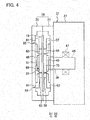
Fig. 1 is a schematic front view of a circular saw machine according to an embodiment of the present invention. -
Fig. 2 is an enlarged view of a main portion of a circular saw machine according to an embodiment of the present invention. -
Fig. 3 is a diagram showing a main portion of an embodiment of the present invention, which is showing a state where a front side of a casing body is opened by a casing rid. -
Fig. 4 is an enlarged view along a IV-IV line inFig. 2 . -
Fig. 5(a) and(b) are diagrams for explaining an operation of a movable saw blade guide set and the like according to an embodiment of the present invention. -
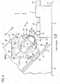
Fig. 6 is a diagram showing a main portion of a first modified example of an embodiment of the present invention, which is showing a state where a front side of a casing body is opened by a casing rid. -
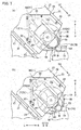
Fig. 7(a) and (b) are diagrams for explaining an operation of a movable saw blade guide set and the like according to a first modified example of an embodiment of the present invention. -
Fig. 8 is a diagram showing a main portion of a second modified example of an embodiment of the present invention, which is showing a state where a front side of a casing body is opened by a casing rid. -
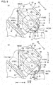
Fig. 9(a) and (b) are diagrams for explaining an operation of a movable saw blade guide set and the like according to a second modified example of an embodiment of the present invention. - The embodiments (including the first modified example and the second modified example) of the present invention will be described with references to the drawings.
- Note that, in the specification and claims of the present application, "provided" is meant to include provided indirectly via another element, besides provided directly, and synonym to "equipped". "equipped" is meant to include equipped indirectly via another element, besides equipped directly, and synonym to "provided". "diameter direction" indicates a diameter direction of the circular saw blade, and "diameter direction inner side" indicates an inner side in the diameter direction of the circular saw blade. "cutting position" indicates a position in a conveying direction in which the cutting processing is carried out. In the figures, "FF" indicates a front direction (conveying direction), "FR" indicates a rear direction, "L" indicates a left direction, "R" indicates a right direction, "U" indicates an upward direction, and "D" indicates a downward direction, respectively.
- The
circular saw machine 1 according to the embodiment of the present invention carries out the cutting processing with respect to a portion to be cut of a rod shaped workpiece W which is positioned to a cutting position in the conveying direction (front direction). Then, a configuration of thecircular saw machine 1 according to the embodiment of the present invention is as follows. - As shown in
Fig. 1 andFig. 2 , thecircular saw machine 1 is equipped with a base mount (bed) 3 extended in a conveying width direction (left and right direction) orthogonal to the conveying direction, and asupport frame 5 provided on a left portion of an upper surface of thisbase mount 3. Thesupport frame 3 has aninclined surface 5f that is inclined with respect to a horizontal direction (left and right direction). - The
base mount 3 is equipped with amain body vice 7 for fixing the workpiece W with respect to thebase mount 3, in an immediately upstream side (immediately upstream side in the conveying direction) of the cutting position in its upper surface (upper surface of the base mount 3). Themain body vice 7 has a vice bed (processing table) 9 provided on the upper surface of thebase mount 3 and supporting the workpiece W. Thevice bed 9 is equipped with a fixedvice jaw 11 on a left portion of its upper surface (upper surface of the vice bed 9). Thevice bed 9 is equipped with amovable vice jaw 13 pinching the workpiece W in cooperation with the fixedvice jaw 11, on its upper surface, and thismovable vice jaw 13 is made to be movable in the conveying width direction. Then, thevice bed 9 is equipped with a hydraulic cylinder forvice 15 that moves themovable vice jaw 13 in the conveying width direction. - Note that the
base mount 3 is equipped with a conveying table (omitted to be shown in the figure) for supporting the workpiece W to be movable in the conveying direction, on its rear side (rear side of the base mount 3). Also, the conveying table is equipped with a conveying vice (omitted to be shown in the figure) for conveying the workpiece W in the conveying direction, at its appropriate position (appropriate position of the conveying table). - The
support frame 5 is equipped with a plurality (only one is shown in the figure) ofguide rails 17 extended in an inclined direction, on itsinclined surface 5f. The plurality ofguide rails 17 are equipped with aprocessing head 21 having acircular saw blade 19 that is capable of rotating, between them (between the plurality of guide rails 17). Thecircular saw blade 19 has a disk shapedbody part 19b, and a plurality (multiplicity) of cuttingteeth 19t provided on an outer circumferential surface of thisbody part 19b. Here, a region positioned on a cutting direction D1 side in thecircular saw blade 19 is made to be acutting region 19A in which the cutting effect is effectuated. - The
processing head 21 is equipped with a plurality of members to be guided 23 which are guided in the cutting direction (one side of the inclined direction) D1 and its opposite direction (another side of the inclined direction) D2 to thecorresponding guide rails 17, on its lower surface (lower surface of the processing head 21). In other words, theprocessing head 21 is provided to be movable in the cutting direction D1 and the opposite direction D2 via the plurality ofguide rails 17 and the plurality of members to be guided 23, on theinclined surface 5f of thesupport frame 5. - The
support frame 5 is equipped with an electric motor for processinghead 25 as an actuator for the processing head that moves theprocessing head 21 in the cutting direction D1 and its opposite direction D2, on its upper portion. Also, an output shaft (omitted to be shown in the figure) of the electric motor for processinghead 25 is coordinated and connected with theprocessing head 21 via a ball screw (omitted to be shown in the figure) and a nut member (omitted to be shown in the figure). Note that, as the actuator for the processing head, a hydraulic cylinder for processing head (omitted to be shown in the figure) may be used. - As shown in
Fig. 2 to Fig. 4 , theprocessing head 21 has amovable box 27 provided to be movable in the cutting direction D1 and its opposite direction D2, on theinclined surface 5f of thesupport frame 5, and asaw blade casing 29 provided on a lower portion of thismovable box 27 and housing a part of thecircular saw blade 19. Also, thesaw blade casing 29 has acasing body 31 provided on a lower portion of themovable box 27, and a casing rid (casing cover) 35 provided on thiscasing body 31 via a plurality ofhinges 33 and capable of opening or closing a front side of thecasing body 31. The casing rid 35 is in a shape approximating thecasing body 31. - The
casing body 31 has afirst rib 37 on an upper portion of its inner side surface (inner side surface of the casing body 31), and a front view of a major part of thisfirst rib 37 is in an L-shape. Thecasing body 31 has aninsertion hole 39 on its central portion (central portion of the casing body 31). Also, the casing rid 35 has asecond rib 41 on an upper portion of its inner side surface (inner side surface of the casing rid 35), and a front view of a major part of thissecond rib 41 is in an L-shape. Thesecond rib 41 is made to be integrally joined with thefirst rib 37 by a plurality ofbolts 43. In other words, the casing rid 35 is made to be integrally joined with thecasing body 31 by the plurality ofbolts 43, in a state where a front side of thecasing body 31 is closed. - The
movable box 27 is equipped with amain shaft 45 via abearing 47 and the like, on its interior (interior of the movable box 27), and thismain shaft 45 is made to be rotatable around its shaft center (shaft center of the main shaft 45). A tip end portion side of themain shaft 45 is inserted into theinsertion hole 39, and on a tip end portion of themain shaft 45, thecircular saw blade 19 is fixed by abolt 51 in a state of being pinched by a pair of attachment flanges (attachment plates) 49. - The
movable box 27 is equipped with an electric motor forcircular saw blade 53 that rotates thecircular saw blade 19, on its upper portion. Also, an output shaft (omitted to be shown in the figure) of the electric motor forcircular saw blade 53 is coordinated and connected to themain shaft 45 via a gear mechanism (omitted to be shown in the figure) and a belt mechanism (omitted to be shown in the figure) provided within the movable box. - The
saw blade casing 29 is equipped with a pair of fixed saw blade guide sets 55 that guide to pinch thebody part 19b of thecircular saw blade 19 on both sides of the cuttingregion 19A in thecircular saw blade 19, at its appropriate position (appropriate position of the saw blade casing 29). The pair of fixed saw blade guide sets 55 are separated in a direction orthogonal to the cutting direction D1. - Each fixed saw blade guide set 55 has a
first bracket 57 fixed to an inner side surface of thecasing body 31, and a first fixedinsert 59 provided at a tip end portion of thisfirst bracket 57 and capable of contacting a back surface of thebody part 19b of thecircular saw blade 19. The first fixedinsert 59 is made of a hard material such as carbide, for example. Also, each fixed saw blade guide set 55 has asecond bracket 61 fixed to an inner side surface of the casing rid 35, and a second fixedinsert 63 provided at a tip end portion of thissecond bracket 61 and capable of contacting a front surface of thebody part 19b of thecircular saw blade 19. The second fixedinsert 63 is made of a hard material such as carbide, for example. - The
casing body 31 is equipped with a pair of first slide guides 65 extended in the cutting direction D1, on its inner side surface (inner side surface of the casing body 31), and a cross section of eachfirst slide guide 65 is in an L-shape. Similarly, the casing rid 35 is equipped with a pair of second slide guides 67 extended in the cutting direction D1, on its inner side surface (inner side surface of the casing rid 35), and a cross section of eachsecond slide guide 67 is in an L-shape. - The
saw blade casing 29 is equipped with a movable saw blade guide set 69 that guides to pinch thebody part 19b of thecircular saw blade 19 in a diameter direction inner side (diameter direction inner side of the circular saw blade 19) of the cuttingregion 19A in thecircular saw blade 19, between the pair of fixed saw blade guide sets 55. The movable saw blade guide set 69 is made to be movable in the cutting direction D1 and the opposite direction D2 via the pair of first slide guides 65 and the pair of second slide guides 67. - The movable saw blade guide set 69 has a first
movable plate 71 provided to be movable in the cutting direction D1 and the opposite direction D2 via the pair of first slide guides 65, on an inner side surface of thecasing body 31. On the firstmovable plate 71, afirst cutout 73 into which theattachment flange 49 is to be inserted is formed, and the firstmovable plate 71 is made to be not in contact with theattachment flange 49. Also, the movable saw blade guide set 69 has a firstmovable insert 75 provided at a tip end portion of the firstmovable plate 71 and capable of contacting a back surface of thebody part 19b of thecircular saw blade 19. The firstmovable insert 75 is made of a hard material such as carbide, for example. - The movable saw blade guide set 69 has a second
movable plate 77 provided to be movable in the cutting direction D1 and the opposite direction D2 via the pair of second slide guides 67, on an inner side surface of the casing rid 35. On the secondmovable plate 77, asecond cutout 79 into which theattachment flange 49 is to be inserted is formed, and the secondmovable plate 77 is made to be not in contact with theattachment flange 49. Also, the movable saw blade guide set 69 has a secondmovable insert 81 provided at a tip end portion of the secondmovable plate 77 and capable of contacting a front surface of thebody part 19b of thecircular saw blade 19. The secondmovable insert 81 is made of a hard material such as carbide, for example. - The
casing body 31 is equipped with afirst stopper 83 for regulating a movement in the cutting direction D1 of the firstmovable plate 71, at an appropriate position on its inner side surface (inner side surface of the casing body 31). Also, thecasing body 31 is equipped with afirst spring 85 as a first biasing member for biasing the firstmovable plate 71 in the cutting direction D1 (to thefirst stopper 83 side), on an upper portion of its inner side surface. - The casing rid 35 is equipped with a
second stopper 87 for regulating a movement in the cutting direction D1 of the secondmovable plate 77, at an appropriate position on its inner side surface (inner side surface of the casing rid 35). Also, the casing rid 35 is equipped with asecond spring 89 as a second biasing member for biasing the secondmovable plate 77 in the cutting direction D1 (to thesecond stopper 87 side), on an upper portion of its inner side surface. - In other words, the
saw blade casing 29 is equipped with thestoppers saw blade casing 29 is equipped with thesprings saw blade casing 29 equipped with thestoppers first bracket 57 and the second bracket 61). - As shown in
Fig. 5(a) and (b) , the movable saw blade guide set 69 is configured to move relatively with respect to theprocessing head 21 in the opposite direction D2 against a biasing force of thesprings circular saw blade 19 progresses. Here, the prescribed abutting state is meant to include a state in which an abutting member (omitted to be shown in the figure) provided on the movable saw blade guide set 69 is abutted to the workpiece W or a fixed portion of thefixed vice jaw 11 and the like, besides a state in which the firstmovable insert 75 and the secondmovable insert 81 are abutted to the workpiece W. - Note that it may be configured such that, when the front side of the
casing body 31 is closed by the casing rid 35, the secondmovable plate 77 is integrally connected to the firstmovable plate 71 by a connection pin (omitted to be shown in the figure) and the like. In this case, either one spring among thefirst spring 85 and thesecond spring 89 may be omitted. - Next, the operation and the effect of the embodiment of the present invention will be described.
- After the workpiece W is conveyed to the conveying table, the workpiece W is conveyed in the conveying direction by the conveying vice, and the portion to be cut of the workpiece W is positioned at the cutting position. Then, by moving the
movable vice jaw 13 to the left direction by the driving of the cylinder forvice 15, the workpiece W is pinched by the cooperation of thefixed vice jaw 11 and themovable vice jaw 13. By this, it is possible to fix the workpiece W with respect to thebase mount 3. - After fixing the workpiece W with respect to the
base mount 3, thecircular saw blade 19 is rotated via the gear mechanism and the belt mechanism by the driving of the electric motor forsaw blade 53. Then, theprocessing head 21 is moved in the cutting direction D1 by the driving of the electric motor for processinghead 25. By this, it is possible to carry out the cutting processing with respect to the portion to be cut of the workpiece W, and take out a product (omitted to be shown in the figure) from the workpiece W. During the cutting processing, the pair of fixed saw blade guide sets 55 will guide to pinch thebody part 19b of thecircular saw blade 19 on both sides of the cuttingregion 19A in thecircular saw blade 19. - Here, as shown in
Fig. 5(a) , until a start of the cutting into the workpiece W by the circular saw blade 19 (immediately after a start of the cutting), the movable saw blade guide set 69 guides to pinch thebody part 19b of thecircular saw blade 19 on a diameter direction inner side of the cuttingregion 19A in thecircular saw blade 19. By this, it is possible to suppress a runout of thecircular saw blade 19 when thecircular saw blade 19 is plunging into the workpiece W (when the cutting into the workpiece W is started), regardless of a size of a width of the workpiece W. - As shown in
Fig. 5(b) , as the cutting into the workpiece by thecircular saw blade 19 progresses, the movable saw blade guide set 69 moves relatively with respect to theprocessing head 21 in the opposite direction D2 against the biasing force of thesprings - After the cutting processing, the
processing head 21 is moved in the opposite direction D2 by the driving of the electric motor for processinghead 25. Then, theprocessing head 21 breaks away from the workpiece W, while the movable saw blade guide set 69 moves relatively with respect to theprocessing head 21 in the cutting direction D1 by the biasing force and the like of thesprings processing head 21 and the movable saw blade guide set 69 can be returned to a state before the cutting processing. - By repeating the above described operation, it is possible to carry out the cutting processing with respect to a plurality of portions to be cut of the workpiece W and take out a plurality of products from the workpiece W.
- As described above, according to the present invention, it is possible to suppress a runout of the
circular saw blade 19 when thecircular saw blade 19 is plunging into the workpiece W, regardless of a size of a width of the workpiece W. Thus, according to the present invention, it is possible to suppress a cutting-bending of thecircular saw blade 19 during the cutting processing, and improve a processing accuracy for a cutting surface of the workpiece W, regardless of a size of a width of the workpiece W. - As shown in
Fig. 6 andFig. 7(a) , in the first modified example of the embodiment of the present invention, thesprings saw blade casing 29 are omitted. Then, thecasing body 31 is equipped with a cylinder for firstmovable plate 91 as an actuator for the first movable plate that moves the firstmovable plate 71 relatively with respect to theprocessing head 21 in the cutting direction D1 and the opposite direction D2, on an upper portion of its inner side surface. Also, the casing rid 35 is equipped with a cylinder for secondmovable plate 93 as an actuator for the second movable plate that moves the secondmovable plate 77 relatively with respect to theprocessing head 21 in the cutting direction D1 and the opposite direction D2, on an upper portion of its inner side surface. - In other words, the
saw blade casing 29 is equipped with the cylinder for firstmovable plate 91 and the cylinder for secondmovable plate 93, on an upper portion of its inner side surface, instead of thesprings - As shown in
Fig. 7(a) , in the first modified example of the embodiment of the present invention, until a start of the cutting into the workpiece W by thecircular saw blade 19, the movable saw blade guide set 69 guides to pinch thebody part 19b of thecircular saw blade 19 on a diameter direction inner side of the cuttingregion 19A in thecircular saw blade 19. By this, it is possible to suppress a runout of thecircular saw blade 19 when thecircular saw blade 19 is plunging into the workpiece W, regardless of a size of a width of the workpiece W. - As shown in
Fig. 7(b) , immediately after the start of the cutting into the workpiece W by thecircular saw blade 19, the movable saw blade guide set 69 (the firstmovable plate 71 and the second movable plate 77) is moved relatively with respect to theprocessing head 21 in the opposite direction D2 by the driving of the cylinder for firstmovable plate 91 and the cylinder for secondmovable plate 93. By this, the firstmovable insert 75 and the secondmovable insert 81 will not be abutted to the workpiece W. Also, the movable saw blade guide set 69 will not be an obstacle in the cutting processing. - After the cutting processing, the movable saw blade guide set 69 (the first
movable plate 71 and the second movable plate 77) is moved relatively with respect to theprocessing head 21 in the cutting direction D1 by the driving of the cylinder for firstmovable plate 91 and the cylinder for secondmovable plate 93. By this, the movable saw blade guide set 69 can be returned to a state before the cutting processing, - Note that, in the case where it is configured such that, when the front side of the
casing body 31 is closed by the casing rid 35, the secondmovable plate 77 is integrally connected to the firstmovable plate 71, either one cylinder among the cylinder for firstmovable plate 91 and the cylinder for secondmovable plate 93 may be omitted. - Then, in the first modified example of the embodiment of the present invention, the effect similar to the effect of the embodiment of the present invention as described above is effectuated.
- As shown in
Fig. 8 andFig. 9(a) , in the second modified example of the embodiment of the present invention, the movable saw blade guide set 69 is divided in a direction orthogonal to the cutting direction D1. In other words, the movable saw blade guide set 69 is configured from a pair of divided saw blade guide sets 69S that are divided in said orthogonal direction. - More specifically, the first
movable plate 71 is configured from a pair of dividedmovable plates 71S that are divided in said orthogonal direction. The firstmovable insert 75 is configured from a pair of dividedmovable inserts 75S that are divided in said orthogonal direction. Also, the secondmovable plate 77 is configured from a pair of dividedmovable plates 77S that are divided in said orthogonal direction. The secondmovable insert 81 is configured from a pair of dividedmovable inserts 81S that are divided in said orthogonal direction. - A movement in the cutting direction D1 of each divided
movable plate 71S is regulated by thefirst stopper 83 provided at an appropriate position on the inner side surface of thecasing body 31. Each dividedmovable plate 71S is biased in the cutting direction D1 (to thefirst stopper 83 side) by thefirst spring 85 provided on an upper portion of the inner side surface of thecasing body 31. Also, a movement in the cutting direction D1 of each dividedmovable plate 77S is regulated by thesecond stopper 87 provided at an appropriate position on the inner side surface of the casing rid 35. Each dividedmovable plate 77S is biased in the cutting direction D1 (to thesecond stopper 87 side) by thesecond spring 89 provided on an upper portion of the inner side surface of the casing rid 35. - As shown in
Fig. 9(a) , in the second modified example of the embodiment of the present invention, until a start of the cutting into the workpiece W by thecircular saw blade 19, the movable saw blade guide set 69 guides to pinch thebody part 19b of thecircular saw blade 19 on a diameter direction inner side of the cuttingregion 19A in thecircular saw blade 19. By this, it is possible to suppress a runout of thecircular saw blade 19 when thecircular saw blade 19 is plunging into the workpiece W. - As shown in
Fig. 9(b) , in the case where a width of the workpiece W is small, as the cutting into the workpiece by thecircular saw blade 19 progresses, only one of the divided saw blade guide set 69S moves relatively with respect to theprocessing head 21 in the opposite direction D2 against the biasing force of thesprings circular saw blade 19 on a diameter direction inner side of the cuttingregion 19A in thecircular saw blade 19. - Then, in the second modified example of the embodiment of the present invention, it is possible to further improve the effect of the embodiment of the present invention as described above.
- Note that the present invention is not to be limited to the description of the embodiments described above, and can be practiced in various embodiments as follows. For example, instead of setting the cutting direction D1 of the
processing head 21 to be a direction inclined with respect to a horizontal direction, it may be set as a horizontal direction or a vertical direction (perpendicular direction). The fixed saw blade guide sets 55 may be omitted from the configuration of the circular saw machine. Then, the scope of the rights encompassed by the present invention is not to be limited to the embodiments described above.
Claims (6)
- A circular saw machine, comprising:a processing head capable of moving in a cutting direction for imparting a cut to a workpiece and its opposite direction, and having a circular saw blade capable of rotating; anda movable saw blade guide set provided to be movable in said cutting direction and said opposite direction on said processing head, for guiding to pinch a body part of said circular saw blade on a diameter direction inner side of a cutting region in which a cutting effect in said circular saw blade is effectuated, said movable saw blade guide set being configured to move relatively with respect to said processing head in said opposite direction, in coordination with a movement in said cutting direction of said processing head, as a cutting into the workpiece progresses.
- The circular saw machine as described in claim 1, further comprising a pair of fixed saw blade guide sets provided to be separated in a direction orthogonal to said cutting direction on said processing head, for guiding to pinch the body part of said circular saw blade on both sides of said cutting region.
- The circular saw machine as described in claim 1 or claim 2, further comprising:a stopper for regulating a movement in said cutting direction of said movable saw blade guide set with respect to said processing head; anda biasing member for biasing said movable saw blade guide set into said cutting direction.
- The circular saw machine as described in claim 1 or claim 2, further comprising an actuator for moving said movable saw blade guide set relatively with respect to said processing head in said cutting direction and said opposite direction.
- The circular saw machine as described in any one of claim 1 to claim 4, wherein said movable saw blade guide set is divided in a direction orthogonal to said cutting direction.
- The circular saw machine as described in any one of claim 1 to claim 5, wherein:said processing head has a saw blade casing for housing said circular saw blade;said saw blade casing has a casing body, and a casing rid provided on said casing body and capable of opening or closing a front side of said casing body; andsaid movable saw blade guide set has: a first movable insert provided to be movable in said cutting direction and said opposite direction on an inner surface of said casing body and being capable of contacting a back surface of the body part of said circular saw blade; and a second movable insert provided to be movable in said cutting direction and said opposite direction on an inner surface of said casing rid and being capable of contacting a front surface of the body part of said circular saw blade.
Applications Claiming Priority (2)
| Application Number | Priority Date | Filing Date | Title |
|---|---|---|---|
| JP2015239901A JP6141951B1 (en) | 2015-12-09 | 2015-12-09 | Circular saw |
| PCT/JP2016/085549 WO2017098979A1 (en) | 2015-12-09 | 2016-11-30 | Circular sawing machine in which wobble of circular saw blade can be suppressed |
Publications (3)
| Publication Number | Publication Date |
|---|---|
| EP3388176A1 true EP3388176A1 (en) | 2018-10-17 |
| EP3388176A4 EP3388176A4 (en) | 2019-08-21 |
| EP3388176B1 EP3388176B1 (en) | 2020-09-02 |
Family
ID=59012052
Family Applications (1)
| Application Number | Title | Priority Date | Filing Date |
|---|---|---|---|
| EP16872878.0A Active EP3388176B1 (en) | 2015-12-09 | 2016-11-30 | Circular sawing machine capable of suppressing runout of circular saw blade |
Country Status (6)
| Country | Link |
|---|---|
| US (1) | US10875107B2 (en) |
| EP (1) | EP3388176B1 (en) |
| JP (1) | JP6141951B1 (en) |
| CN (1) | CN108367368B (en) |
| TW (1) | TWI621493B (en) |
| WO (1) | WO2017098979A1 (en) |
Families Citing this family (4)
| Publication number | Priority date | Publication date | Assignee | Title |
|---|---|---|---|---|
| KR20200010270A (en) | 2017-05-26 | 2020-01-30 | 닛토덴코 가부시키가이샤 | Magnet manufacturing method and magnet magnetization method |
| EP3479943B1 (en) * | 2017-11-02 | 2022-01-05 | F.O.M. Industrie S.r.l. | Cutting-off machine to cut section bars, in particular made of aluminium, light alloys, pvc or the like |
| CN113909561B (en) * | 2021-10-27 | 2022-08-30 | 江苏恒力组合机床有限公司 | Numerical control saw cutting system for steel rail |
| CN119870592B (en) * | 2025-03-26 | 2025-07-15 | 山西凯得森建筑科技有限公司 | A sawing machine for cutting profiles |
Family Cites Families (23)
| Publication number | Priority date | Publication date | Assignee | Title |
|---|---|---|---|---|
| US2589309A (en) * | 1946-08-27 | 1952-03-18 | Ralph R Roemer | Circular saw safety guard |
| US2941451A (en) * | 1956-05-02 | 1960-06-21 | Hughes Aircraft Co | Cutter support |
| BE571800A (en) * | 1957-10-07 | |||
| DE2043599B2 (en) | 1970-09-03 | 1972-08-31 | Trennjäger Maschinenfabrik, 5350 Euskirchen | METAL COLD SAW |
| DE2646515A1 (en) | 1976-10-15 | 1978-04-20 | Leopold Jaegers | GUIDE FOR A SAW BLADE |
| SE416322B (en) * | 1978-05-08 | 1980-12-15 | Tord Erik Birger Eriksson | ASFALTSKERARE |
| JPS5837541Y2 (en) | 1979-02-06 | 1983-08-24 | 株式会社アマダ | Band saw blade guide device |
| FR2451814A1 (en) * | 1979-03-23 | 1980-10-17 | Petitjean Graniterie | STABILIZING DEVICE FOR A ROTATING DIAMOND DISC IN A STONE WORKING MACHINE |
| DE3239986A1 (en) * | 1982-10-28 | 1984-05-03 | Robert Bosch Gmbh, 7000 Stuttgart | HAND MACHINE TOOL WITH A DISC-SHAPED TOOL |
| JP2779944B2 (en) * | 1989-03-14 | 1998-07-23 | 富士鋼業株式会社 | Anti-sway device for circular saw machine |
| JPH0416302A (en) * | 1990-05-09 | 1992-01-21 | Ishita:Kk | Sawing device |
| US5142825A (en) * | 1991-04-25 | 1992-09-01 | Floyd Kenneth R | Hand-held elongated stock material cutter |
| JP2781364B2 (en) | 1995-09-22 | 1998-07-30 | 津根精機株式会社 | Circular saw cutting machine |
| JPH07227714A (en) * | 1994-02-17 | 1995-08-29 | Kitagawa Denki:Kk | Circular saw cutter |
| US6722046B2 (en) * | 2001-09-04 | 2004-04-20 | Ben L Evenson | Portable forward cutting power saw |
| CA2448479C (en) * | 2002-11-12 | 2009-05-05 | Makita Corporation | Power tools |
| CN102407383B (en) * | 2010-09-20 | 2013-08-07 | 力山工业股份有限公司 | Cutting machine with vertically lifting saw blade |
| CN102407381B (en) * | 2010-09-21 | 2014-06-04 | 苏州宝时得电动工具有限公司 | Portable cutting machine |
| DE102011050189A1 (en) | 2011-05-06 | 2012-11-08 | Herbert Arnold Gmbh & Co. Kg | Stabilizing device for a cutting disc |
| EP2737968B1 (en) * | 2011-07-27 | 2020-03-25 | Kanefusa Kabushiki Kaisha | Cutting machine |
| JP5177779B1 (en) * | 2012-04-06 | 2013-04-10 | 鷲尾 潤子 | Saw blade support device and method of cutting with saw machine |
| JP5839712B2 (en) * | 2012-11-29 | 2016-01-06 | 鷲尾 潤子 | Saw blade support device and method of cutting with saw machine |
| CN203992635U (en) * | 2014-06-06 | 2014-12-10 | 上海通用汽车有限公司 | Sawing machine safety guard |
-
2015
- 2015-12-09 JP JP2015239901A patent/JP6141951B1/en active Active
-
2016
- 2016-11-30 WO PCT/JP2016/085549 patent/WO2017098979A1/en not_active Ceased
- 2016-11-30 EP EP16872878.0A patent/EP3388176B1/en active Active
- 2016-11-30 US US16/060,613 patent/US10875107B2/en active Active
- 2016-11-30 CN CN201680071805.2A patent/CN108367368B/en active Active
- 2016-12-08 TW TW105140635A patent/TWI621493B/en active
Also Published As
| Publication number | Publication date |
|---|---|
| CN108367368A (en) | 2018-08-03 |
| EP3388176A4 (en) | 2019-08-21 |
| US10875107B2 (en) | 2020-12-29 |
| TW201726284A (en) | 2017-08-01 |
| JP6141951B1 (en) | 2017-06-07 |
| JP2017104929A (en) | 2017-06-15 |
| WO2017098979A1 (en) | 2017-06-15 |
| TWI621493B (en) | 2018-04-21 |
| EP3388176B1 (en) | 2020-09-02 |
| US20180369938A1 (en) | 2018-12-27 |
| CN108367368B (en) | 2020-01-07 |
Similar Documents
| Publication | Publication Date | Title |
|---|---|---|
| EP3388176B1 (en) | Circular sawing machine capable of suppressing runout of circular saw blade | |
| KR101382389B1 (en) | Fixing apparatus for workpiece | |
| CN104259876A (en) | Self-centering clamp | |
| US10010924B2 (en) | Cutting die | |
| CN108818703B (en) | Section device of button bar | |
| CN106976133B (en) | Numerical control sawing and milling machine for door pocket | |
| KR20170064659A (en) | Forming appartus for joint stopper of wire | |
| KR101449366B1 (en) | Fixing apparatus for workpiece | |
| KR101732993B1 (en) | Plano miller | |
| KR101449367B1 (en) | Fixing apparatus for workpiece | |
| JP6655337B2 (en) | Band sawing machine | |
| CN120619488A (en) | Multi-angle deburring device with adjustable auto-parts processing | |
| KR20180010556A (en) | Machine tool | |
| KR102268738B1 (en) | Machine tool | |
| KR101457844B1 (en) | Fixing apparatus for workpiece | |
| JP6948985B2 (en) | Machine tool cover device | |
| US3313193A (en) | Circular saw with a vertical tool feed | |
| CN104936732B (en) | Cutting-off method and shearing device | |
| JP2017127972A (en) | Circular saw | |
| US10005162B2 (en) | Machine tool including chip conveyor | |
| CN222113250U (en) | Pushing machine table of hydraulic rod | |
| CN222492393U (en) | Die steel processing positioning device | |
| WO2020038370A1 (en) | Stop mechanism and cutting machine | |
| KR100793381B1 (en) | Pipe cutting equipment | |
| CN215615904U (en) | Pipe device is cut in pay-off |
Legal Events
| Date | Code | Title | Description |
|---|---|---|---|
| STAA | Information on the status of an ep patent application or granted ep patent |
Free format text: STATUS: THE INTERNATIONAL PUBLICATION HAS BEEN MADE |
|
| PUAI | Public reference made under article 153(3) epc to a published international application that has entered the european phase |
Free format text: ORIGINAL CODE: 0009012 |
|
| STAA | Information on the status of an ep patent application or granted ep patent |
Free format text: STATUS: REQUEST FOR EXAMINATION WAS MADE |
|
| 17P | Request for examination filed |
Effective date: 20180709 |
|
| AK | Designated contracting states |
Kind code of ref document: A1 Designated state(s): AL AT BE BG CH CY CZ DE DK EE ES FI FR GB GR HR HU IE IS IT LI LT LU LV MC MK MT NL NO PL PT RO RS SE SI SK SM TR |
|
| AX | Request for extension of the european patent |
Extension state: BA ME |
|
| DAV | Request for validation of the european patent (deleted) | ||
| DAX | Request for extension of the european patent (deleted) | ||
| A4 | Supplementary search report drawn up and despatched |
Effective date: 20190719 |
|
| RIC1 | Information provided on ipc code assigned before grant |
Ipc: B23D 47/00 20060101AFI20190715BHEP Ipc: B23D 45/02 20060101ALI20190715BHEP |
|
| GRAP | Despatch of communication of intention to grant a patent |
Free format text: ORIGINAL CODE: EPIDOSNIGR1 |
|
| STAA | Information on the status of an ep patent application or granted ep patent |
Free format text: STATUS: GRANT OF PATENT IS INTENDED |
|
| INTG | Intention to grant announced |
Effective date: 20200331 |
|
| GRAS | Grant fee paid |
Free format text: ORIGINAL CODE: EPIDOSNIGR3 |
|
| GRAA | (expected) grant |
Free format text: ORIGINAL CODE: 0009210 |
|
| STAA | Information on the status of an ep patent application or granted ep patent |
Free format text: STATUS: THE PATENT HAS BEEN GRANTED |
|
| RAP1 | Party data changed (applicant data changed or rights of an application transferred) |
Owner name: AMADA MACHINERY CO., LTD. Owner name: AMADA CO., LTD. |
|
| RAP1 | Party data changed (applicant data changed or rights of an application transferred) |
Owner name: AMADA CO., LTD. Owner name: AMADA MACHINERY CO., LTD. |
|
| AK | Designated contracting states |
Kind code of ref document: B1 Designated state(s): AL AT BE BG CH CY CZ DE DK EE ES FI FR GB GR HR HU IE IS IT LI LT LU LV MC MK MT NL NO PL PT RO RS SE SI SK SM TR |
|
| REG | Reference to a national code |
Ref country code: GB Ref legal event code: FG4D |
|
| REG | Reference to a national code |
Ref country code: AT Ref legal event code: REF Ref document number: 1308269 Country of ref document: AT Kind code of ref document: T Effective date: 20200915 Ref country code: CH Ref legal event code: EP |
|
| REG | Reference to a national code |
Ref country code: DE Ref legal event code: R096 Ref document number: 602016043481 Country of ref document: DE |
|
| REG | Reference to a national code |
Ref country code: IE Ref legal event code: FG4D |
|
| REG | Reference to a national code |
Ref country code: LT Ref legal event code: MG4D |
|
| PG25 | Lapsed in a contracting state [announced via postgrant information from national office to epo] |
Ref country code: NO Free format text: LAPSE BECAUSE OF FAILURE TO SUBMIT A TRANSLATION OF THE DESCRIPTION OR TO PAY THE FEE WITHIN THE PRESCRIBED TIME-LIMIT Effective date: 20201202 Ref country code: GR Free format text: LAPSE BECAUSE OF FAILURE TO SUBMIT A TRANSLATION OF THE DESCRIPTION OR TO PAY THE FEE WITHIN THE PRESCRIBED TIME-LIMIT Effective date: 20201203 Ref country code: BG Free format text: LAPSE BECAUSE OF FAILURE TO SUBMIT A TRANSLATION OF THE DESCRIPTION OR TO PAY THE FEE WITHIN THE PRESCRIBED TIME-LIMIT Effective date: 20201202 Ref country code: SE Free format text: LAPSE BECAUSE OF FAILURE TO SUBMIT A TRANSLATION OF THE DESCRIPTION OR TO PAY THE FEE WITHIN THE PRESCRIBED TIME-LIMIT Effective date: 20200902 Ref country code: FI Free format text: LAPSE BECAUSE OF FAILURE TO SUBMIT A TRANSLATION OF THE DESCRIPTION OR TO PAY THE FEE WITHIN THE PRESCRIBED TIME-LIMIT Effective date: 20200902 Ref country code: LT Free format text: LAPSE BECAUSE OF FAILURE TO SUBMIT A TRANSLATION OF THE DESCRIPTION OR TO PAY THE FEE WITHIN THE PRESCRIBED TIME-LIMIT Effective date: 20200902 Ref country code: HR Free format text: LAPSE BECAUSE OF FAILURE TO SUBMIT A TRANSLATION OF THE DESCRIPTION OR TO PAY THE FEE WITHIN THE PRESCRIBED TIME-LIMIT Effective date: 20200902 |
|
| REG | Reference to a national code |
Ref country code: NL Ref legal event code: MP Effective date: 20200902 |
|
| REG | Reference to a national code |
Ref country code: AT Ref legal event code: MK05 Ref document number: 1308269 Country of ref document: AT Kind code of ref document: T Effective date: 20200902 |
|
| PG25 | Lapsed in a contracting state [announced via postgrant information from national office to epo] |
Ref country code: LV Free format text: LAPSE BECAUSE OF FAILURE TO SUBMIT A TRANSLATION OF THE DESCRIPTION OR TO PAY THE FEE WITHIN THE PRESCRIBED TIME-LIMIT Effective date: 20200902 Ref country code: PL Free format text: LAPSE BECAUSE OF FAILURE TO SUBMIT A TRANSLATION OF THE DESCRIPTION OR TO PAY THE FEE WITHIN THE PRESCRIBED TIME-LIMIT Effective date: 20200902 Ref country code: RS Free format text: LAPSE BECAUSE OF FAILURE TO SUBMIT A TRANSLATION OF THE DESCRIPTION OR TO PAY THE FEE WITHIN THE PRESCRIBED TIME-LIMIT Effective date: 20200902 |
|
| PG25 | Lapsed in a contracting state [announced via postgrant information from national office to epo] |
Ref country code: CZ Free format text: LAPSE BECAUSE OF FAILURE TO SUBMIT A TRANSLATION OF THE DESCRIPTION OR TO PAY THE FEE WITHIN THE PRESCRIBED TIME-LIMIT Effective date: 20200902 Ref country code: PT Free format text: LAPSE BECAUSE OF FAILURE TO SUBMIT A TRANSLATION OF THE DESCRIPTION OR TO PAY THE FEE WITHIN THE PRESCRIBED TIME-LIMIT Effective date: 20210104 Ref country code: RO Free format text: LAPSE BECAUSE OF FAILURE TO SUBMIT A TRANSLATION OF THE DESCRIPTION OR TO PAY THE FEE WITHIN THE PRESCRIBED TIME-LIMIT Effective date: 20200902 Ref country code: EE Free format text: LAPSE BECAUSE OF FAILURE TO SUBMIT A TRANSLATION OF THE DESCRIPTION OR TO PAY THE FEE WITHIN THE PRESCRIBED TIME-LIMIT Effective date: 20200902 Ref country code: SM Free format text: LAPSE BECAUSE OF FAILURE TO SUBMIT A TRANSLATION OF THE DESCRIPTION OR TO PAY THE FEE WITHIN THE PRESCRIBED TIME-LIMIT Effective date: 20200902 |
|
| PG25 | Lapsed in a contracting state [announced via postgrant information from national office to epo] |
Ref country code: AL Free format text: LAPSE BECAUSE OF FAILURE TO SUBMIT A TRANSLATION OF THE DESCRIPTION OR TO PAY THE FEE WITHIN THE PRESCRIBED TIME-LIMIT Effective date: 20200902 Ref country code: AT Free format text: LAPSE BECAUSE OF FAILURE TO SUBMIT A TRANSLATION OF THE DESCRIPTION OR TO PAY THE FEE WITHIN THE PRESCRIBED TIME-LIMIT Effective date: 20200902 Ref country code: ES Free format text: LAPSE BECAUSE OF FAILURE TO SUBMIT A TRANSLATION OF THE DESCRIPTION OR TO PAY THE FEE WITHIN THE PRESCRIBED TIME-LIMIT Effective date: 20200902 Ref country code: IS Free format text: LAPSE BECAUSE OF FAILURE TO SUBMIT A TRANSLATION OF THE DESCRIPTION OR TO PAY THE FEE WITHIN THE PRESCRIBED TIME-LIMIT Effective date: 20210102 |
|
| REG | Reference to a national code |
Ref country code: DE Ref legal event code: R097 Ref document number: 602016043481 Country of ref document: DE |
|
| PG25 | Lapsed in a contracting state [announced via postgrant information from national office to epo] |
Ref country code: MC Free format text: LAPSE BECAUSE OF FAILURE TO SUBMIT A TRANSLATION OF THE DESCRIPTION OR TO PAY THE FEE WITHIN THE PRESCRIBED TIME-LIMIT Effective date: 20200902 Ref country code: SK Free format text: LAPSE BECAUSE OF FAILURE TO SUBMIT A TRANSLATION OF THE DESCRIPTION OR TO PAY THE FEE WITHIN THE PRESCRIBED TIME-LIMIT Effective date: 20200902 |
|
| REG | Reference to a national code |
Ref country code: CH Ref legal event code: PL |
|
| PLBE | No opposition filed within time limit |
Free format text: ORIGINAL CODE: 0009261 |
|
| STAA | Information on the status of an ep patent application or granted ep patent |
Free format text: STATUS: NO OPPOSITION FILED WITHIN TIME LIMIT |
|
| PG25 | Lapsed in a contracting state [announced via postgrant information from national office to epo] |
Ref country code: LU Free format text: LAPSE BECAUSE OF NON-PAYMENT OF DUE FEES Effective date: 20201130 |
|
| 26N | No opposition filed |
Effective date: 20210603 |
|
| REG | Reference to a national code |
Ref country code: BE Ref legal event code: MM Effective date: 20201130 |
|
| PG25 | Lapsed in a contracting state [announced via postgrant information from national office to epo] |
Ref country code: DK Free format text: LAPSE BECAUSE OF FAILURE TO SUBMIT A TRANSLATION OF THE DESCRIPTION OR TO PAY THE FEE WITHIN THE PRESCRIBED TIME-LIMIT Effective date: 20200902 Ref country code: CH Free format text: LAPSE BECAUSE OF NON-PAYMENT OF DUE FEES Effective date: 20201130 Ref country code: LI Free format text: LAPSE BECAUSE OF NON-PAYMENT OF DUE FEES Effective date: 20201130 Ref country code: SI Free format text: LAPSE BECAUSE OF FAILURE TO SUBMIT A TRANSLATION OF THE DESCRIPTION OR TO PAY THE FEE WITHIN THE PRESCRIBED TIME-LIMIT Effective date: 20200902 |
|
| REG | Reference to a national code |
Ref country code: IE Ref legal event code: MM4A |
|
| PG25 | Lapsed in a contracting state [announced via postgrant information from national office to epo] |
Ref country code: IE Free format text: LAPSE BECAUSE OF NON-PAYMENT OF DUE FEES Effective date: 20201130 |
|
| PG25 | Lapsed in a contracting state [announced via postgrant information from national office to epo] |
Ref country code: TR Free format text: LAPSE BECAUSE OF FAILURE TO SUBMIT A TRANSLATION OF THE DESCRIPTION OR TO PAY THE FEE WITHIN THE PRESCRIBED TIME-LIMIT Effective date: 20200902 Ref country code: MT Free format text: LAPSE BECAUSE OF FAILURE TO SUBMIT A TRANSLATION OF THE DESCRIPTION OR TO PAY THE FEE WITHIN THE PRESCRIBED TIME-LIMIT Effective date: 20200902 Ref country code: CY Free format text: LAPSE BECAUSE OF FAILURE TO SUBMIT A TRANSLATION OF THE DESCRIPTION OR TO PAY THE FEE WITHIN THE PRESCRIBED TIME-LIMIT Effective date: 20200902 |
|
| PG25 | Lapsed in a contracting state [announced via postgrant information from national office to epo] |
Ref country code: MK Free format text: LAPSE BECAUSE OF FAILURE TO SUBMIT A TRANSLATION OF THE DESCRIPTION OR TO PAY THE FEE WITHIN THE PRESCRIBED TIME-LIMIT Effective date: 20200902 |
|
| PG25 | Lapsed in a contracting state [announced via postgrant information from national office to epo] |
Ref country code: BE Free format text: LAPSE BECAUSE OF NON-PAYMENT OF DUE FEES Effective date: 20201130 |
|
| P01 | Opt-out of the competence of the unified patent court (upc) registered |
Effective date: 20230428 |
|
| PG25 | Lapsed in a contracting state [announced via postgrant information from national office to epo] |
Ref country code: NL Free format text: LAPSE BECAUSE OF NON-PAYMENT OF DUE FEES Effective date: 20200923 |
|
| PGFP | Annual fee paid to national office [announced via postgrant information from national office to epo] |
Ref country code: GB Payment date: 20241120 Year of fee payment: 9 |
|
| PGFP | Annual fee paid to national office [announced via postgrant information from national office to epo] |
Ref country code: IT Payment date: 20241126 Year of fee payment: 9 |
|
| PGFP | Annual fee paid to national office [announced via postgrant information from national office to epo] |
Ref country code: DE Payment date: 20251119 Year of fee payment: 10 |
|
| PGFP | Annual fee paid to national office [announced via postgrant information from national office to epo] |
Ref country code: FR Payment date: 20251126 Year of fee payment: 10 |