EP2737968B1 - Cutting machine - Google Patents
Cutting machine Download PDFInfo
- Publication number
- EP2737968B1 EP2737968B1 EP12817349.9A EP12817349A EP2737968B1 EP 2737968 B1 EP2737968 B1 EP 2737968B1 EP 12817349 A EP12817349 A EP 12817349A EP 2737968 B1 EP2737968 B1 EP 2737968B1
- Authority
- EP
- European Patent Office
- Prior art keywords
- guides
- work
- tool
- disc
- pairs
- Prior art date
- Legal status (The legal status is an assumption and is not a legal conclusion. Google has not performed a legal analysis and makes no representation as to the accuracy of the status listed.)
- Active
Links
- 230000002093 peripheral effect Effects 0.000 description 9
- 238000004891 communication Methods 0.000 description 6
- 239000010953 base metal Substances 0.000 description 5
- 230000000052 comparative effect Effects 0.000 description 3
- 238000005242 forging Methods 0.000 description 3
- 239000000463 material Substances 0.000 description 3
- 239000002184 metal Substances 0.000 description 3
- 229910052751 metal Inorganic materials 0.000 description 3
- 238000005452 bending Methods 0.000 description 2
- 230000001276 controlling effect Effects 0.000 description 2
- 229910003460 diamond Inorganic materials 0.000 description 2
- 239000010432 diamond Substances 0.000 description 2
- 238000005259 measurement Methods 0.000 description 2
- 238000012986 modification Methods 0.000 description 2
- 230000004048 modification Effects 0.000 description 2
- 239000011347 resin Substances 0.000 description 2
- 229920005989 resin Polymers 0.000 description 2
- 229910000838 Al alloy Inorganic materials 0.000 description 1
- CWYNVVGOOAEACU-UHFFFAOYSA-N Fe2+ Chemical compound [Fe+2] CWYNVVGOOAEACU-UHFFFAOYSA-N 0.000 description 1
- 229910000831 Steel Inorganic materials 0.000 description 1
- 238000001514 detection method Methods 0.000 description 1
- 230000001105 regulatory effect Effects 0.000 description 1
- 238000007493 shaping process Methods 0.000 description 1
- 239000010959 steel Substances 0.000 description 1
Images


Classifications
-
- B—PERFORMING OPERATIONS; TRANSPORTING
- B23—MACHINE TOOLS; METAL-WORKING NOT OTHERWISE PROVIDED FOR
- B23D—PLANING; SLOTTING; SHEARING; BROACHING; SAWING; FILING; SCRAPING; LIKE OPERATIONS FOR WORKING METAL BY REMOVING MATERIAL, NOT OTHERWISE PROVIDED FOR
- B23D47/00—Sawing machines or sawing devices working with circular saw blades, characterised only by constructional features of particular parts
- B23D47/005—Vibration-damping
Definitions
- the present invention relates to a cutting machine configured to rotate a disc-like tool to cut work by the disc-like tool as per the preamble of claim 1.
- the cutting machine disclosed in Japanese Laid-Open Patent Publication No. 2004-338081 is a circular saw.
- the circular saw has a saw head rotatably retaining a disc-like tool, and a pair of guides provided on the saw head.
- the pair of guides face both sides of the disc-like tool.
- Guides having any shape can be selected in accordance with the diameter of the disc-like tool.
- the guides are set such that the distal ends of the guides and the outer peripheral edge of the disc-like tool are in the vicinity of each other.
- the guide has a guide main body provided on the saw head, a retaining member tiltably provided on the guide main body, and a contact member mounted to the retaining member so that the contact member faces the disc-like tool.
- the angle of the retaining member with respect to the guide main body is fixed prior to cutting such that the tip end portion of the contact member and the outer peripheral edge of the disc-like tool are in the vicinity of each other.
- the deflection of the outer peripheral edge of the disc-like tool which involves a relatively large deflection, is regulated by the pair of guides.
- the work can be cut at a right angle with high precision.
- US2941451 discloses a cutting machine as per the preamble of claim 1.
- a cutting machine configured to cut work by a disc-like tool that is rotated.
- the cutting machine has a disc-like tool, a saw head, two pairs of guides, and a variable device.
- the disc-like tool has two sides.
- the saw head rotatably holds the disc-like tool.
- the two pairs of guides are provided on the saw head. Each pair of the guides face the two sides of the disc-like tool.
- the variable device varies the distance between the two pairs of guides such that when an object is to be cut by the disc-like tool, the work passes between the two pairs of guides.
- the disc-like tool cuts the work while rotating, and the work passes between the two pairs of guides.
- the two pairs of guides regulate deflection in the axial direction (curving during sawing) of the disc-like tool at both end sides of a cutting arc of the work. Since the distance between the two pairs of guides is variable, it is possible to make the distance between the two pairs of guides variable according to the configuration of the work. Thus, when the work is to pass between the two pairs of guides, the distance between the two pairs of guides increases thereby, making it possible for the work to pass between the two pairs of guides.
- the distance between the two pairs of guides is fixed from the start so that the work can pass between the two pairs of guides.
- the distance between the guides is set to be sufficiently large in conformity with the maximum diameter of the work.
- the present invention makes it possible to reduce the distance between the two pairs of guides. By reducing the distance between the two pairs of guides, it is possible to reduce the distance between the cutting position and the guides.
- it is possible to cut the work so as to obtain a cut surface at a predetermined angle precisely and smoothly.
- a cutting machine 1 is a circular saw.
- the cutting machine 1 has a base 21 and a saw head 10.
- the saw head 10 is movably mounted to the base 21 through a rail 26 provided on the base 21.
- the saw head 10 has a head main body 22 and a motor 25.
- the motor 25 is connected to a drive shaft 11 of the head main body 22 by a belt 24 and a pulley so as to be capable of transmitting force.
- the head main body 22 has the drive shaft 11, a back cover 16 and a front cover 17.
- a disc-like tool (saw blade) 2 is attached to the drive shaft 11.
- the drive shaft 11 is rotated by power from the motor 25, and the disc-like tool 2 is rotated around the drive shaft 11.
- the disc-like tool is of a disc-like configuration, and has a base metal portion 2a in the central region, and a cutting region 2b in the outer peripheral region thereof.
- the disc-like tool 2 is a circular saw blade, a plurality of cutting edges formed of a hard material such as cemented carbide or diamond are attached to the cutting region 2b.
- the disc-like tool 2 is an abrasive grinding wheel, diamond grains, cemented carbide grains or the like are glued to the cutting region 2b.
- the disc-like tool 2 it is desirable for the disc-like tool 2 to be thin.
- the amount of chips generated at the time of cutting is small.
- the cutting resistance at the time of cutting is small, and the requisite amount of energy at the time of cutting is small.
- the disc-like tool 2 is thin, the stiffness in the thickness direction of the disc-like tool 2 is low, and the disc-like tool 2 is subject to deflection in the axial direction at the time of cutting.
- the saw head 10 is provided with a plurality of guides 3 and 4 suppressing deflection in the thickness direction (the axial direction) of the disc-like tool 2.
- the saw head 10 has the back cover 16 and the front cover 17.
- the back cover 16 covers the disc-like tool 2 from the back.
- a guide 3b is mounted to the lower region of the back cover 16 via a mounting member 6.
- a guide 4b is movably mounted to the upper region of the back cover 16.
- the front cover 17 is connected to the back cover 16 such that one end portion thereof is rotatable with respect to the back cover 16.
- the front cover 17 is movable through rotation between a closed position where it covers the front of the disc-like tool 2, and an open position where it opens the front of the disc-like tool 2.
- a guide 3a is mounted to the lower region of the front cover 17 via a mounting member 6.
- a guide 4a is movably mounted to the upper region of the front cover 17.
- variable device 1a makes the distance between the guides 3 and 4 variable.
- the variable device 1a has a retaining mechanism 5 movably retaining the guides 4 with respect to the saw head 10, and a moving mechanism 1b configured to move the guides 4 according to the configuration of the work 20 at the time of cutting.
- the retaining mechanism 5 has arms 5a, rails 5b, and connection members 5c.
- the arms 5a are of a plate-like configuration and extend arcuately.
- Each of the rails 5b has an arcuately extending hole, and the arms 5a are movably inserted into the holes.
- Each rail 5b is mounted to the front cover 17 and to the back cover 16.
- Each rail 5b retains each arm 5a such that the arm 5a is concentrically movable with respect to the rotation of the disc-like tool 2.
- each rail 5b has a back portion 5b1 supporting the arm 5a from the back, a front portion 5b2 supporting the arm 5a from the front, an arcuate lower portion 5b3 supporting the arm 5a from below, and an arcuate upper portion 5b4 covering the arm 5a from above.
- each connection member 5c is mounted to the distal end portion of each arm 5a.
- Each connection member 5c extends from each arm 5a radially outward with respect to the disc-like tool 2.
- the connection members 5c respectively provided on the front cover 17 and on the back cover 16 are integrally connected together by a mounting member when the front cover 17 is at the closed position. As a result, the two arms 5a move integrally with respect to the saw head 10.
- gap adjustment plates 9 and guides 4 are mounted to the tip end portions of the arms 5a.
- the gap adjustment plates 9 and the guides 4 are mounted to surfaces of the arms 5a and the surfaces face the disc-like tool 2.
- the thickness of the gap adjustment plates is determined by the size of the gaps between the guides 4 and the disc-like tool 2.
- guides 3a, 3b, 4a and 4b are of a plate-like configuration, and have guide surfaces facing the front side or the back side of the base metal portion 2a of the disc-like tool 2. Small gaps are formed between the guides 3a, 3b, 4a and 4b and the disc-like tool 2.
- the pair of guides 3a and 3b is provided at a corresponding height and face each other.
- the disc-like tool 2 is installed between the guides 3a and 3b.
- the pair of guides 3a and 3b is installed under the work.
- the tip ends of the guides 3a and 3b are set in the vicinity of the cutting region 2b of the disc-like tool 2.
- the pair of guides 4a and 4b is respectively mounted to the arms 5a at positions where they face each other.
- the pair of guides 4a and 4b move together with the arms 5a and always face each other.
- the disc-like tool 2 is installed between the pair of guides 4a and 4b.
- the pair of guides 4a and 4b is situated above the other pair of guides 3a and 3b.
- the pair of guides 4a and 4b is situated at the same height as the work 20.
- the pair of guides 4a and 4b is moved upward by the moving mechanism 1b. As a result, the distance between the upper and lower guides 3 and 4 varies.
- the moving mechanism 1b has a biasing body 8 and a sliding member 7.
- the biasing body 8 has a cylinder utilizing pneumatic pressure, and is provided on the back of the back cover 16.
- the biasing body 8 is connected with the connection member 5c provided on the back cover 16, and constantly biases the connection member 5c clockwise.
- the arms 5a are biased clockwise by the biasing force of the biasing body, and the upper guides 4 are biased toward the lower guides 3.
- the sliding members 7 are formed of resin. As shown in FIGS. 4 and 5 , the sliding members 7 are mounted to the arm 5a mounted to the back cover 16.
- the sliding member 7 is of an L-shaped configuration, and integrally has a lower side portion 7a and a front end portion 7b.
- the lower side portion 7a is mounted to the lower side edge of the tip end portion of the arm 5a, and protrudes below the guide 4b.
- the front end portion 7b is mounted to the front edge of the tip end portion of the arm 5a, and protrudes forwards beyond the guide 4b (in the direction of the work 20).
- the guides 3 are mounted to the mounting members 6 by bolts 18.
- Each bolt 18 has a hole, and the mounting members 6 have communication holes communicating with the holes of the bolts 18. Air, oil, or both air and oil in a mist-like state is supplied to the communication holes of the mounting members 6. Air, oil or the like is blown from the guides 3 toward the disc-like tool 2 through the communication holes and the holes of the bolts 18. As a result, the frictional resistance generated when the disc-like tool 2 and the guides 3 contact each other is reduced.
- the guides 4 are mounted to the arms 5a by the bolts 18.
- the arms 5a have communication holes communicating with the holes of the bolts 18. Air, oil, or both air and oil are supplied to the communication holes of the arms 5a. Air or oil is blown from the guides 4 toward the disc-like tool 2 through the communication holes and the holes of the bolts 18. As a result, the frictional resistance generated when the disc-like tool 2 and the guides 4 contact each other is reduced.
- the base 21 is provided with a vise device 1c holding the work 20.
- the vise device 1c has a lower jaw 12, an upper jaw 15, a stationary jaw 13 and a movable jaw 14.
- the lower jaw 12 is fixed to the base 12, and supports the work 20 from below.
- the upper jaw 15 is provided so as to be vertically movable with respect to the base 21, and presses the work 20 toward the lower jaw 12.
- the stationary jaw 13 is fixed to the base 21, and supports the work 20 from one side.
- the movable jaw 14 is provided so as to be horizontally movable with respect to the base 21, and presses the work 20 toward the stationary jaw 13.
- the movable jaw 14 has a slit 14a and an inclined surface 14b.
- the disc-like tool 2 is inserted into the slit 14a, which allows the disc-like tool 2 to reach the work 20.
- the inclined surface 14b is formed at the upper end surface of the movable jaw 14, and is oriented upward and toward the sliding member 7.
- the work 20 is elongated, and consists of a round bar, a pipe, a plate or the like.
- the work 20 is formed, for example, of metal (steel, non-ferrous metal or the like) or resin.
- the cutting machine 1 has a feeding device 19 feeding the work 20 in the longitudinal direction, a releasing device (not shown) configured to move the upper jaw 15 and the movable jaw 14, and a control device (not shown) configured to control the feeding device 19 and the releasing device.
- the control device controls the releasing device to move the upper jaw 15 and the movable jaw 14 away from the work 20.
- the control device uses the feeding device 19 to feed the work 20 by a predetermined length before controlling the releasing device to press the upper jaw 15 and the movable jaw 14 against the work 20.
- the work 20 When cutting the work 20 by the cutting machine 1, the work 20 is set in the vise device 1c as shown in FIG. 3 .
- the disc-like tool 2 is set on the drive shaft 11, and the front cover 17 is closed, and the pair of connection members 5c are connected.
- the disc-like tool 2 is rotated, and the saw head 10 is moved toward the work 20 by a feeding device 23.
- the sliding member 7 contacts the inclined surface 14b of the movable jaw 14, and moves upward along the inclined surface 14b.
- the disc-like tool 2 contacts the work 20, and gradually cuts the work 20.
- the distance between the upper and lower guides 3 and 4 is relatively small.
- the sliding member 7 contacts the outer peripheral surface of the work 20, and moves upward along the outer peripheral surface of the work 20.
- the arms 5a move against the biasing force of the biasing body 8 of FIG. 3
- the upper guides 4 move upward.
- the upper guides 4 move along the contour of the work 20 while maintaining a predetermined distance between the outer surface of the work 20 and themselves.
- the guides 4 do not contact the work 20, and move at a substantially predetermined distance from the outer peripheral surface of the work 20.
- the distance between the upper and lower guides 3 and 4 gradually increases during cutting, allowing the work 20 to enter between the upper and lower guides 3 and 4.
- the cutting region 2b of the disc-like tool 2 passes through the work 20 to thereby cut the work 20.
- the disc-like tool 2 may undergo axial runout.
- the base metal portion 2a contacts the guides 3 and 4, and the axial runout of the disc-like tool 2 is restricted by the guides 3 and 4.
- the control device controls the feeding device 23 to restore the saw head 10 to the former position.
- the arms 5a are moved by the biasing body 8, and the upper guides 4 move toward the lower guides 3.
- the control device controls the releasing device and the feeding device 19, and the work 20 moves in the longitudinal direction.
- the work 20 is held again by the vise device 1c.
- the work 20 is cut in the same manner as described above to cut a plurality of small pieces off the work 20. Small pieces of the work 20 are used as material, for example, during forging.
- a tipped saw blade (of an outer diameter of 300 mm having a blade thickness of 1.1 mm, a base metal portion thickness of 0.8 mm, a hole diameter of 40 mm, and a number of teeth of 60) was prepared as the disc-like tool 2.
- An aluminum alloy (A6061 of JIS Standard) having a diameter of 70 mm was prepared as the work 20.
- the cutting conditions were set to 1250 RPM, a feeding rate of 0.025 mm/tooth, and a clearance between the guides 3 and 4 and the base metal portion 2a of 0.01 mm.
- FIG. 8 shows the results of an experiment, illustrating the relationship between the stiffness of the disc-like tool 2 and the distance between the upper and lower guides 3 and 4.
- the distance between the upper and lower guides 3 and 4 was set to a predetermined distance.
- a force toward the guides 3 and 4 was applied to the disc-like tool 2.
- the measurement results are summarized in FIG. 8 .
- the smaller the distance between the guides 3 and 4 the higher the stiffness of the disc-like tool 2, and the more difficult it is to deform the disc-like tool 2.
- the guides are stationary as in the prior art, for example, in the case where the upper and lower guides are stationary, it is necessary to set the distance between the upper and lower guides to a distance not smaller than one allowing at least the work 20 to pass therebetween. Further, taking variation in the diameter of the work 20 into consideration, it is necessary to set the distance between the upper and lower guides larger than the diameter of the work 20.
- the stiffness of the disc-like tool 2 is rather low. It is not easy to make the angle of the cut surface of the work 20 a predetermined angle (which is normally a right angle). It is not easy to obtain a smooth cut surface.
- the cutting machine 1 has the disc-like tool 2, the saw head 10, the two pairs of guides 3 and 4, and the variable device 1a.
- the disc-like tool 2 has two sides.
- the saw head 10 rotatably retains the disc-like tool 2.
- the two pairs of guides 3 and 4 are provided on the saw head 10.
- the guides 3 and 4 of each pair face the both sides of the disc-like tool 2.
- the variable device 1 varies the distance between the two pairs of guides 3 and 4 so that the work 20 can pass between the guides 3 and 4.
- the disc-like tool 2 cuts the work 20 while rotating, and the work 20 passes between the two pairs of guides 3 and 4.
- the two pairs of guides 3 and 4 regulate the axial deflection (curving during sawing) of the disc-like tool 2 on both sides (upper and lower sides) of the work 20.
- the distance between the two pairs of guides 3 and 4 is variable, it is possible to make the distance between the two pairs of guides variable in accordance with the configuration of the work 20.
- the distance between the two pairs of guides is fixed from the start such that the work 20 can pass between the two pairs of guides.
- the distance between the guides is set sufficiently large in conformity with the maximum diameter of the work 20.
- that of the present embodiment makes it possible to reduce the distance between the two pairs of guides 3 and 4.
- variable device 1a further has the retaining mechanism 5 and the moving mechanism 1b.
- the retaining mechanism 5 movably retains the pair of guides 4 with respect to the saw head 10.
- the moving mechanism 1b moves the pair of guides 4 in accordance with the configuration of the work 20 to be cut by the disc-like tool 2.
- the work 20 passes between the guides 3 and 4, and the distance between the two pairs of guides 3 and 4 varies in accordance with the configuration of the work 20.
- the moving mechanism 1b further has the biasing body 8 and the sliding member 7.
- the biasing body 8 biases the pair of guides 4 so as to reduce the distance between the two pairs of guides 3 and 4.
- the sliding member 7 is provided on the pair of guides 4, and slides while in contact with the work 20 to be cut by the disc-like tool 2.
- the distance between the two pairs of guides 4 and 5 is at a minimum before the cutting.
- the sliding member 7 contacts the work 20.
- the guides 4 move together with the sliding member 7 against the biasing force of the biasing body 8.
- the distance between the two pairs of guides 3 and 4 increases.
- the distance between the two pairs of guides 3 and 4 is changed in correspondence with the configuration of the work 20.
- the retaining mechanism 5 further has arms 5a and rails 5b.
- the pair of guides 4 are attached to the arms 5a.
- the rails 5b retain the arms 5a such that the arms 5a move in a concentric circle; the center of which is at the center of the disc-like tool 2.
- the guides 4 move concentrically with respect to the disc-like tool 2.
- the guides 4 are set so as to move along the cutting region 2b.
- FIGS. 9 to 13 a cutting machine as illustrated in FIGS. 9 to 13 .
- the cutting machine illustrated in FIGS. 9 to 13 has a pair of guides 30, another pair of guides 31, and a variable device (not shown).
- the pairs of guides 30 and 31 are provided so as to be movable with respect to the saw head 10.
- the variable device has a retaining mechanism and a moving mechanism.
- the retaining mechanism retains the guides 30 and 31 such that they are movable with respect to the saw head 10.
- the moving mechanism moves the guides 30 and 31 in correspondence with the configuration of the work 20 at the time of cutting.
- the guides 30 and 31 shown in FIGS. 9 to 13 have first protrusions 30a and 31a, second protrusions 30b and 31b, and recesses 30c and 31c.
- First protrusion 30a protrudes from an end portion of the guide 30 and towards the other guide 31 on the side of the cutting region 2b of the disc-like tool 2.
- Second protrusion 30b protrudes from the opposite end portion of the guide 30 and towards the other guide 31 on the side of the center of the disk-like tool.
- First protrusion 31a protrudes from an end portion of the guide 31 and towards the other guide 30 on the side of the cutting region 2b of the disc-like tool 2.
- Second protrusion 31b protrudes from the opposite end portion of the guide 31 and towards the other guide 30 on the side of the center of the disk-like tool 2.
- the recesses 30c and 31c are of a configuration in conformity with the contour of the work 20.
- the recesses 30c and 31c are of a larger size than the work 20, and exhibit, for example, a radius of curvature larger than the radius of the work 20. As a result, the work 20 is accommodated between the recesses 30c and 31c.
- FIG. 15 shows a cutting machine to be compared with the cutting machine shown in FIG. 9 .
- the depth of cut in the case of the cutting machine shown in FIG. 14 and the depth of cut of the disc-like tool 2 thereof were analyzed.
- the results of the analysis are plotted in points 35 in FIG. 15 .
- the cutting machine of FIG. 14 has a pair of guides 32 and another pair of guides 33.
- the pairs of guides 32 and 33 are immovably mounted to the saw head 10.
- the distance between the guides 32 and 33 is fixed so as to be larger than the maximum diameter of the work 20 intended to be cut.
- the distance between the guides 32 and 33 is always kept fixed during the time of cutting.
- the warp in the case of the cutting machine shown in FIG. 9 indicated by points 34 is smaller than that in the case of the cutting machine shown in FIG. 14 indicated by points 35.
- the depth of cut is zero.
- the peak value of the warp indicated by points 34 is smaller than that indicated by points 35.
- the length of time that the peak value continues indicated by points 34 is shorter than that indicated by points 35.
- the warp increase ratio at the initial stage of depth of cut indicated by points 34 is smaller than that indicated by points 35, with the difference being large.
- the saw-curving amount is obtained from an integral of the depth of cut and the warp, and is indicated by a region in FIG. 15 .
- the saw-curving amount indicated by the region formed by points 34 is smaller than that indicated by the region formed by points 35.
- the former is approximately a quarter of the latter. That is, the saw-curving amount in the case of the cutting machine of FIG. 9 is smaller than that in the case of the cutting machine of FIG. 15 . It can be seen, from FIG. 15 , that the main reason for this lies in the difference in the warp increase ratio at the initial stage of depth of cut.
- variable device 1a may have the retaining mechanism 5 which retains the upper guides 4 and the moving mechanism 1b which moves the guides 4.
- the variable device 1a may have a retaining mechanism for retaining the lower guides 3 and a moving mechanism for moving the lower guides 3.
- the moving mechanism 1b may have the biasing body 8 and the sliding member 7.
- the moving mechanism 1b may have a drive mechanism for moving the arms 5a and a control device for controlling the drive mechanism.
- the control device controls the drive mechanism based on work information previously input or a detection signal from a sensor for measuring the configuration of the work. As a result, it is possible to move the guides 4 together with the arms 5a in correspondence with the configuration of the work 20.
- the moving mechanism 1b may move the guides 4 in conformity with the contour of the work 20. Alternatively, it may move the guides 4 in conformity with the general configuration of the contour of the work 20. Alternatively, it also may move the guides 4 gently in conformity with the configuration of the work 20.
- the retaining mechanism 5 may retain the guides 4 so as to allow them to move in a circle concentric with the disc-like tool 2.
- the retaining mechanism 5 may retain the guides 4 so as to allow them to move in a curve akin to a circle concentric with the disc-like tool 2 or in a straight line.
- the biasing body 8 may have a cylinder configured to generate a biasing force through pneumatic pressure.
- the biasing body 8 may consist of a spring or rubber generating a biasing force through a resilient force.
- the biasing body 8 may consist of a gas spring configured to generate a biasing force through gas pressure.
- the disc-like tool 2 may have the cutting region 2b at the outer peripheral edge thereof.
- the disc-like tool 2 may have the cutting region at the inner peripheral edge thereof.
- the cutting machine 1 may have two pairs of guides 3 and 4. Alternatively, the cutting machine 1 may have three or more pairs of guides.
Landscapes
- Engineering & Computer Science (AREA)
- Mechanical Engineering (AREA)
- Sawing (AREA)
Description
- The present invention relates to a cutting machine configured to rotate a disc-like tool to cut work by the disc-like tool as per the preamble of claim 1.
- The cutting machine disclosed in Japanese Laid-Open Patent Publication No.
2004-338081 - Thus, in the case where the disc-like tool is deflected in the direction of the rotation axis when cutting work (i.e., in the case of curving during sawing), the deflection of the outer peripheral edge of the disc-like tool, which involves a relatively large deflection, is regulated by the pair of guides. As a result, the work can be cut at a right angle with high precision.
-
US2941451 discloses a cutting machine as per the preamble of claim 1. - However, there has been a need for a cutting machine capable of cutting work with higher precision. For example, when the work to be cut by the cutting machine is a metal member, and the short piece obtained through the cutting is to be used as the material for forging, the configuration of the forging is affected by the configuration of the short piece. Thus, there has been a need for a cutting machine capable of shaping the configuration of the short piece with higher precision, that is, capable of cutting work so as to obtain a cut surface at a predetermined angle precisely and smoothly.
- This problem is solved by a cutting machine comprising the combination of features of claim 1. According to an aspect of the present invention, there is provided a cutting machine configured to cut work by a disc-like tool that is rotated. The cutting machine has a disc-like tool, a saw head, two pairs of guides, and a variable device. The disc-like tool has two sides. The saw head rotatably holds the disc-like tool. The two pairs of guides are provided on the saw head. Each pair of the guides face the two sides of the disc-like tool. The variable device varies the distance between the two pairs of guides such that when an object is to be cut by the disc-like tool, the work passes between the two pairs of guides.
- Thus, at the time of cutting, the disc-like tool cuts the work while rotating, and the work passes between the two pairs of guides. The two pairs of guides regulate deflection in the axial direction (curving during sawing) of the disc-like tool at both end sides of a cutting arc of the work. Since the distance between the two pairs of guides is variable, it is possible to make the distance between the two pairs of guides variable according to the configuration of the work. Thus, when the work is to pass between the two pairs of guides, the distance between the two pairs of guides increases thereby, making it possible for the work to pass between the two pairs of guides.
- In contrast, in a conventional cutting machine, the distance between the two pairs of guides is fixed from the start so that the work can pass between the two pairs of guides. Thus, the distance between the guides is set to be sufficiently large in conformity with the maximum diameter of the work. Thus, as compared with the conventional cutting machine, the present invention makes it possible to reduce the distance between the two pairs of guides. By reducing the distance between the two pairs of guides, it is possible to reduce the distance between the cutting position and the guides. Thus, it is possible to suppress deflection in the axial direction of the disc-like tool, in particular, deflection in the axial direction of the disc-like tool between the two pairs of guides, which corresponds to the region where the work is cut. As a result, it is possible to cut the work so as to obtain a cut surface at a predetermined angle precisely and smoothly.
-
-
FIG. 1 is a front view of a cutting machine; -
FIG. 2 is a partial front view of a saw head; -
FIG. 3 is a partial perspective view of the cutting machine with a front cover at an open position; -
FIG. 4 is an enlarged partial perspective view of the cutting machine; -
FIG. 5 is an enlarged partial front view of the cutting machine when the cutting of work is started; -
FIG. 6 is an enlarged partial front view of the cutting machine when the work is being cut; -
FIG. 7 is a cross-sectional view taken along line VII-VII inFIG. 2 ; -
FIG. 8 is a chart illustrating a relationship between stiffness and a distance between the upper and lower guides; -
FIG. 9 is a front view of guides, a disc-like tool, and work in a cutting machine according to another embodiment; -
FIG. 10 is a front view of the guides, the disc-like tool, and the work in the cutting machine ofFIG. 9 when the cutting of the work is started; -
FIG. 11 is a front view of the guides, the disc-like tool, and the work in the cutting machine ofFIG. 9 when the work has been cut further than in the state shown inFIG. 10 ; -
FIG. 12 is a front view of the guides, the disc-like tool, and the work in the cutting machine ofFIG. 9 when the work has been cut further than in the state shown inFIG. 11 ; -
FIG. 13 is a front view of the guides, the disc-like tool, and the work in the cutting machine ofFIG. 9 when the cutting of the work has been completed; -
FIG. 14 is a front view of guides, a disc-like tool, and work in a cutting machine according to a comparative example in which a pair of guides are immovably mounted to a saw head; and -
FIG. 15 is a chart illustrating a relationship between a depth of cut and a warp of the disc-like tool in the cutting machines ofFIGS. 9 and14 . - An embodiment of the present invention will be described with reference to
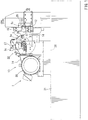
FIGS. 1 to 8 . As shown inFIG. 1 , a cutting machine 1 is a circular saw. The cutting machine 1 has abase 21 and asaw head 10. Thesaw head 10 is movably mounted to thebase 21 through arail 26 provided on thebase 21. Thesaw head 10 has a headmain body 22 and amotor 25. Themotor 25 is connected to adrive shaft 11 of the headmain body 22 by abelt 24 and a pulley so as to be capable of transmitting force. - As shown in
FIGS. 1 and2 , the headmain body 22 has thedrive shaft 11, aback cover 16 and afront cover 17. A disc-like tool (saw blade) 2 is attached to thedrive shaft 11. Thedrive shaft 11 is rotated by power from themotor 25, and the disc-like tool 2 is rotated around thedrive shaft 11. - As shown in
FIGS. 2 and3 , the disc-like tool is of a disc-like configuration, and has abase metal portion 2a in the central region, and acutting region 2b in the outer peripheral region thereof. When the disc-like tool 2 is a circular saw blade, a plurality of cutting edges formed of a hard material such as cemented carbide or diamond are attached to thecutting region 2b. When the disc-like tool 2 is an abrasive grinding wheel, diamond grains, cemented carbide grains or the like are glued to thecutting region 2b. - It is desirable for the disc-
like tool 2 to be thin. When the disc-like tool 2 is thin, the amount of chips generated at the time of cutting is small. Further, when the disc-like tool 2 is thin, the cutting resistance at the time of cutting is small, and the requisite amount of energy at the time of cutting is small. However, since the disc-like tool 2 is thin, the stiffness in the thickness direction of the disc-like tool 2 is low, and the disc-like tool 2 is subject to deflection in the axial direction at the time of cutting. In contrast, thesaw head 10 is provided with a plurality ofguides like tool 2. - As shown in
FIG. 3 , thesaw head 10 has theback cover 16 and thefront cover 17. Theback cover 16 covers the disc-like tool 2 from the back. Aguide 3b is mounted to the lower region of theback cover 16 via a mountingmember 6. Aguide 4b is movably mounted to the upper region of theback cover 16. - As shown in
FIG. 3 , thefront cover 17 is connected to theback cover 16 such that one end portion thereof is rotatable with respect to theback cover 16. Thefront cover 17 is movable through rotation between a closed position where it covers the front of the disc-like tool 2, and an open position where it opens the front of the disc-like tool 2. Aguide 3a is mounted to the lower region of thefront cover 17 via a mountingmember 6. Aguide 4a is movably mounted to the upper region of thefront cover 17. - As shown in
FIGS. 2 and3 , theback cover 16 and thefront cover 17 are provided with avariable device 1a making the distance between theguides variable device 1a has aretaining mechanism 5 movably retaining theguides 4 with respect to thesaw head 10, and a movingmechanism 1b configured to move theguides 4 according to the configuration of thework 20 at the time of cutting. - As shown in
FIGS. 3 and7 , theretaining mechanism 5 hasarms 5a, rails 5b, andconnection members 5c. Thearms 5a are of a plate-like configuration and extend arcuately. Each of therails 5b has an arcuately extending hole, and thearms 5a are movably inserted into the holes. Eachrail 5b is mounted to thefront cover 17 and to theback cover 16. Eachrail 5b retains eacharm 5a such that thearm 5a is concentrically movable with respect to the rotation of the disc-like tool 2. - As shown in
FIGS. 3 ,4 and7 , eachrail 5b has a back portion 5b1 supporting thearm 5a from the back, a front portion 5b2 supporting thearm 5a from the front, an arcuate lower portion 5b3 supporting thearm 5a from below, and an arcuate upper portion 5b4 covering thearm 5a from above. - As shown in
FIG. 3 , eachconnection member 5c is mounted to the distal end portion of eacharm 5a. Eachconnection member 5c extends from eacharm 5a radially outward with respect to the disc-like tool 2. Theconnection members 5c respectively provided on thefront cover 17 and on theback cover 16 are integrally connected together by a mounting member when thefront cover 17 is at the closed position. As a result, the twoarms 5a move integrally with respect to thesaw head 10. - As shown in
FIG. 7 ,gap adjustment plates 9 and guides 4 are mounted to the tip end portions of thearms 5a. Thegap adjustment plates 9 and theguides 4 are mounted to surfaces of thearms 5a and the surfaces face the disc-like tool 2. The thickness of the gap adjustment plates is determined by the size of the gaps between theguides 4 and the disc-like tool 2. - As shown in
FIGS. 3 and4 , guides 3a, 3b, 4a and 4b are of a plate-like configuration, and have guide surfaces facing the front side or the back side of thebase metal portion 2a of the disc-like tool 2. Small gaps are formed between theguides like tool 2. The pair ofguides like tool 2 is installed between theguides guides guides region 2b of the disc-like tool 2. - As shown in
FIGS. 3 and4 , the pair ofguides arms 5a at positions where they face each other. Thus, the pair ofguides arms 5a and always face each other. The disc-like tool 2 is installed between the pair ofguides guides guides work 20 is cut, the pair ofguides work 20. At the time of cutting, the pair ofguides mechanism 1b. As a result, the distance between the upper andlower guides - As shown in
FIG. 3 , the movingmechanism 1b has a biasingbody 8 and a slidingmember 7. The biasingbody 8 has a cylinder utilizing pneumatic pressure, and is provided on the back of theback cover 16. The biasingbody 8 is connected with theconnection member 5c provided on theback cover 16, and constantly biases theconnection member 5c clockwise. As a result, thearms 5a are biased clockwise by the biasing force of the biasing body, and theupper guides 4 are biased toward the lower guides 3. - The sliding
members 7 are formed of resin. As shown inFIGS. 4 and5 , the slidingmembers 7 are mounted to thearm 5a mounted to theback cover 16. The slidingmember 7 is of an L-shaped configuration, and integrally has alower side portion 7a and afront end portion 7b. Thelower side portion 7a is mounted to the lower side edge of the tip end portion of thearm 5a, and protrudes below theguide 4b. Thefront end portion 7b is mounted to the front edge of the tip end portion of thearm 5a, and protrudes forwards beyond theguide 4b (in the direction of the work 20). - As shown in
FIG. 3 , theguides 3 are mounted to the mountingmembers 6 bybolts 18. Eachbolt 18 has a hole, and the mountingmembers 6 have communication holes communicating with the holes of thebolts 18. Air, oil, or both air and oil in a mist-like state is supplied to the communication holes of the mountingmembers 6. Air, oil or the like is blown from theguides 3 toward the disc-like tool 2 through the communication holes and the holes of thebolts 18. As a result, the frictional resistance generated when the disc-like tool 2 and theguides 3 contact each other is reduced. - As shown in
FIGS. 3 and7 , theguides 4 are mounted to thearms 5a by thebolts 18. Thearms 5a have communication holes communicating with the holes of thebolts 18. Air, oil, or both air and oil are supplied to the communication holes of thearms 5a. Air or oil is blown from theguides 4 toward the disc-like tool 2 through the communication holes and the holes of thebolts 18. As a result, the frictional resistance generated when the disc-like tool 2 and theguides 4 contact each other is reduced. - As shown in
FIG. 4 , thebase 21 is provided with avise device 1c holding thework 20. Thevise device 1c has alower jaw 12, anupper jaw 15, astationary jaw 13 and amovable jaw 14. Thelower jaw 12 is fixed to thebase 12, and supports thework 20 from below. Theupper jaw 15 is provided so as to be vertically movable with respect to thebase 21, and presses thework 20 toward thelower jaw 12. Thestationary jaw 13 is fixed to thebase 21, and supports thework 20 from one side. Themovable jaw 14 is provided so as to be horizontally movable with respect to thebase 21, and presses thework 20 toward thestationary jaw 13. - As shown in
FIGS. 4 and5 , themovable jaw 14 has aslit 14a and aninclined surface 14b. The disc-like tool 2 is inserted into theslit 14a, which allows the disc-like tool 2 to reach thework 20. Theinclined surface 14b is formed at the upper end surface of themovable jaw 14, and is oriented upward and toward the slidingmember 7. - As shown in
FIG. 4 , thework 20 is elongated, and consists of a round bar, a pipe, a plate or the like. Thework 20 is formed, for example, of metal (steel, non-ferrous metal or the like) or resin. The cutting machine 1 has afeeding device 19 feeding thework 20 in the longitudinal direction, a releasing device (not shown) configured to move theupper jaw 15 and themovable jaw 14, and a control device (not shown) configured to control thefeeding device 19 and the releasing device. - After a small piece is cut from the
work 20, the control device controls the releasing device to move theupper jaw 15 and themovable jaw 14 away from thework 20. The control device then uses thefeeding device 19 to feed thework 20 by a predetermined length before controlling the releasing device to press theupper jaw 15 and themovable jaw 14 against thework 20. As a result, it is possible for the cutting machine 1 to successively cut a plurality of small pieces from thework 20. - When cutting the
work 20 by the cutting machine 1, thework 20 is set in thevise device 1c as shown inFIG. 3 . The disc-like tool 2 is set on thedrive shaft 11, and thefront cover 17 is closed, and the pair ofconnection members 5c are connected. The disc-like tool 2 is rotated, and thesaw head 10 is moved toward thework 20 by afeeding device 23. - As shown in
FIGS. 5 and 6 , the slidingmember 7 contacts theinclined surface 14b of themovable jaw 14, and moves upward along theinclined surface 14b. The disc-like tool 2 contacts thework 20, and gradually cuts thework 20. At the start of the cutting of thework 20, the distance between the upper andlower guides - Next, as shown in
FIGS. 5 and 6 , the slidingmember 7 contacts the outer peripheral surface of thework 20, and moves upward along the outer peripheral surface of thework 20. As a result, thearms 5a move against the biasing force of the biasingbody 8 ofFIG. 3 , and theupper guides 4 move upward. Theupper guides 4 move along the contour of thework 20 while maintaining a predetermined distance between the outer surface of thework 20 and themselves. Thus, theguides 4 do not contact thework 20, and move at a substantially predetermined distance from the outer peripheral surface of thework 20. - As shown in
FIGS. 5 and 6 , the distance between the upper andlower guides work 20 to enter between the upper andlower guides region 2b of the disc-like tool 2 passes through thework 20 to thereby cut thework 20. - When the balance in cutting force between the both sides is lost due to wear or the like, the disc-
like tool 2 may undergo axial runout. When the disc-like tool 2 undergoes axial runout, thebase metal portion 2a contacts theguides like tool 2 is restricted by theguides - After a small piece has been cut off the
work 20, the control device controls thefeeding device 23 to restore thesaw head 10 to the former position. Thearms 5a are moved by the biasingbody 8, and theupper guides 4 move toward the lower guides 3. The control device controls the releasing device and thefeeding device 19, and thework 20 moves in the longitudinal direction. Thework 20 is held again by thevise device 1c. Thework 20 is cut in the same manner as described above to cut a plurality of small pieces off thework 20. Small pieces of thework 20 are used as material, for example, during forging. - An experiment was conducted by using the cutting machine 1. In the experiment, a tipped saw blade (of an outer diameter of 300 mm having a blade thickness of 1.1 mm, a base metal portion thickness of 0.8 mm, a hole diameter of 40 mm, and a number of teeth of 60) was prepared as the disc-
like tool 2. An aluminum alloy (A6061 of JIS Standard) having a diameter of 70 mm was prepared as thework 20. The cutting conditions were set to 1250 RPM, a feeding rate of 0.025 mm/tooth, and a clearance between theguides base metal portion 2a of 0.01 mm. - When cutting the
work 20 by the cutting machine 1, theupper guides 4 moved upward, and the distance between the upper andlower guides work 20 by the cutting machine 1, the cut surface of thework 20 was measured. The measurement result showed that the bending amount of the cut surface was 0.057 mm. In a comparative experiment, thework 20 was cut, with the distance between theguides work 20 in the comparative experiment was 0.094 mm. Thus, it was found out that it is possible to cut so as to obtain a smooth cut surface of thework 20 by making the distance between the upper andlower guides -
FIG. 8 shows the results of an experiment, illustrating the relationship between the stiffness of the disc-like tool 2 and the distance between the upper andlower guides lower guides guides like tool 2. The stiffness (the requisite force for effecting deformation by 1 mm) in the axial direction (thickness direction) of the disc-like tool 2 at an intermediate position between theguides 3 and theguides 4. The measurement results are summarized inFIG. 8 . As can be seen inFIG. 8 , the smaller the distance between theguides like tool 2, and the more difficult it is to deform the disc-like tool 2. Thus, it can be seen that it is desirable to cut thework 20 while making the distance between theguides work 20 while making the distance between theguides work 20 with high precision. - On the other hand, in the case where the guides are stationary as in the prior art, for example, in the case where the upper and lower guides are stationary, it is necessary to set the distance between the upper and lower guides to a distance not smaller than one allowing at least the
work 20 to pass therebetween. Further, taking variation in the diameter of thework 20 into consideration, it is necessary to set the distance between the upper and lower guides larger than the diameter of thework 20. Thus, in the cutting machine in which the guides are stationary, the stiffness of the disc-like tool 2 is rather low. It is not easy to make the angle of the cut surface of the work 20 a predetermined angle (which is normally a right angle). It is not easy to obtain a smooth cut surface. - As described above, as shown in
FIGS. 1 and2 , the cutting machine 1 has the disc-like tool 2, thesaw head 10, the two pairs ofguides variable device 1a. The disc-like tool 2 has two sides. Thesaw head 10 rotatably retains the disc-like tool 2. The two pairs ofguides saw head 10. Theguides like tool 2. When thework 20 is to be cut by the disc-like tool 2, the variable device 1 varies the distance between the two pairs ofguides work 20 can pass between theguides - Thus, at the time of cutting, the disc-
like tool 2 cuts thework 20 while rotating, and thework 20 passes between the two pairs ofguides guides like tool 2 on both sides (upper and lower sides) of thework 20. Further, since the distance between the two pairs ofguides work 20. Thus, when thework 20 passes between the two pairs ofguides guides work 20 to pass between the two pairs ofguides - In contrast, in the conventional cutting machine, the distance between the two pairs of guides is fixed from the start such that the
work 20 can pass between the two pairs of guides. Thus, the distance between the guides is set sufficiently large in conformity with the maximum diameter of thework 20. Thus, as compared with the conventional cutting machine, that of the present embodiment makes it possible to reduce the distance between the two pairs ofguides like tool 2, in particular, axial deflection of the disc-like tool 2 between the two pairs of guides, i.e., in the region where thework 20 is cut. As a result, it is possible to cut the work at a predetermined angle precisely and smoothly by the disc-like tool. - As shown in
FIG. 3 , thevariable device 1a further has theretaining mechanism 5 and the movingmechanism 1b. Theretaining mechanism 5 movably retains the pair ofguides 4 with respect to thesaw head 10. The movingmechanism 1b moves the pair ofguides 4 in accordance with the configuration of thework 20 to be cut by the disc-like tool 2. Thus, at the time of cutting, thework 20 passes between theguides guides work 20. As a result, it is possible for the two pairs ofguides work 20 at the time of cutting. - As shown in
FIG. 3 , the movingmechanism 1b further has the biasingbody 8 and the slidingmember 7. The biasingbody 8 biases the pair ofguides 4 so as to reduce the distance between the two pairs ofguides member 7 is provided on the pair ofguides 4, and slides while in contact with thework 20 to be cut by the disc-like tool 2. Thus, due to the biasingbody 8, the distance between the two pairs ofguides work 20 passes between the two pairs ofguides member 7 contacts thework 20. Theguides 4 move together with the slidingmember 7 against the biasing force of the biasingbody 8. The distance between the two pairs ofguides guides work 20. - As shown in
FIG. 3 , theretaining mechanism 5 further hasarms 5a andrails 5b. The pair ofguides 4 are attached to thearms 5a. Therails 5b retain thearms 5a such that thearms 5a move in a concentric circle; the center of which is at the center of the disc-like tool 2. Thus, due to theretaining mechanism 5, theguides 4 move concentrically with respect to the disc-like tool 2. Thus, theguides 4 are set so as to move along the cuttingregion 2b. As a result, it is always possible for theguides 4 to suppress axial runout of the disc-like tool at a position in the vicinity of the cuttingregion 2b. Thus, it is possible to effectively suppress the axial runout of the disc-like tool 2. - While the embodiments of invention have been described with reference to specific configurations, it will be apparent to those skilled in the art that many alternatives, modifications and variations may be made without departing from the scope of the present invention. Accordingly, embodiments of the present invention are intended to embrace all such alternatives, modifications and variations that may fall within the scope of the appended claims. For example, embodiments of the present invention should not be limited to the representative configurations, but may be modified, for example, as described below.
- Instead of the cutting machine illustrated in
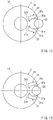
FIGS. 1 to 8 , it is also possible to adopt a cutting machine as illustrated inFIGS. 9 to 13 . The cutting machine illustrated inFIGS. 9 to 13 has a pair ofguides 30, another pair ofguides 31, and a variable device (not shown). The pairs ofguides saw head 10. The variable device has a retaining mechanism and a moving mechanism. The retaining mechanism retains theguides saw head 10. The moving mechanism moves theguides work 20 at the time of cutting. - The
guides FIGS. 9 to 13 havefirst protrusions second protrusions First protrusion 30a protrudes from an end portion of theguide 30 and towards theother guide 31 on the side of the cuttingregion 2b of the disc-like tool 2.Second protrusion 30b protrudes from the opposite end portion of theguide 30 and towards theother guide 31 on the side of the center of the disk-like tool.First protrusion 31a protrudes from an end portion of theguide 31 and towards theother guide 30 on the side of the cuttingregion 2b of the disc-like tool 2.Second protrusion 31b protrudes from the opposite end portion of theguide 31 and towards theother guide 30 on the side of the center of the disk-like tool 2. Therecesses work 20. Therecesses work 20, and exhibit, for example, a radius of curvature larger than the radius of thework 20. As a result, thework 20 is accommodated between therecesses - As shown in
FIGS. 9 to 11 , when thesaw head 10 is moved toward thework 20, theguide 30 moves upward in conformity with the configuration of thework 20. Theguide 31 moves downward, and the distance between theguides FIGS. 12 and13 , after the center of thework 20 gets beyond the line connecting thefirst protrusions guide 30 moves downward in conformity with the configuration of thework 20, and theguide 31 moves upward. As a result, the distance between theguides - The depth of cut of the
work 20 and the warp of the disc-like tool 2 were analyzed. The results of the analysis are plotted inpoints 34 ofFIG. 15 . The warp indicated inFIG. 15 is the maximum warp at the tip end portion of the disc-like tool 2 and between theguides FIG. 14 shows a cutting machine to be compared with the cutting machine shown inFIG. 9 . The depth of cut in the case of the cutting machine shown inFIG. 14 and the depth of cut of the disc-like tool 2 thereof were analyzed. The results of the analysis are plotted inpoints 35 inFIG. 15 . - The cutting machine of
FIG. 14 has a pair ofguides 32 and another pair ofguides 33. The pairs ofguides saw head 10. The distance between theguides work 20 intended to be cut. Thus, the distance between theguides - As shown in
FIG. 15 , assuming that the cut of depth is the same, the warp in the case of the cutting machine shown inFIG. 9 indicated bypoints 34 is smaller than that in the case of the cutting machine shown inFIG. 14 indicated bypoints 35. At the first and last points with respect topoints points 34 is smaller than that indicated bypoints 35. The length of time that the peak value continues indicated bypoints 34 is shorter than that indicated bypoints 35. The warp increase ratio at the initial stage of depth of cut indicated bypoints 34 is smaller than that indicated bypoints 35, with the difference being large. - The saw-curving amount is obtained from an integral of the depth of cut and the warp, and is indicated by a region in
FIG. 15 . Thus, the saw-curving amount indicated by the region formed bypoints 34 is smaller than that indicated by the region formed bypoints 35. The former is approximately a quarter of the latter. That is, the saw-curving amount in the case of the cutting machine ofFIG. 9 is smaller than that in the case of the cutting machine ofFIG. 15 . It can be seen, fromFIG. 15 , that the main reason for this lies in the difference in the warp increase ratio at the initial stage of depth of cut. - As shown in
FIG. 3 , thevariable device 1a may have theretaining mechanism 5 which retains theupper guides 4 and the movingmechanism 1b which moves theguides 4. Instead of theretaining mechanism 5 and the movingmechanism 1b, thevariable device 1a may have a retaining mechanism for retaining thelower guides 3 and a moving mechanism for moving the lower guides 3. - The moving
mechanism 1b may have the biasingbody 8 and the slidingmember 7. Alternatively, the movingmechanism 1b may have a drive mechanism for moving thearms 5a and a control device for controlling the drive mechanism. The control device controls the drive mechanism based on work information previously input or a detection signal from a sensor for measuring the configuration of the work. As a result, it is possible to move theguides 4 together with thearms 5a in correspondence with the configuration of thework 20. - The moving
mechanism 1b may move theguides 4 in conformity with the contour of thework 20. Alternatively, it may move theguides 4 in conformity with the general configuration of the contour of thework 20. Alternatively, it also may move theguides 4 gently in conformity with the configuration of thework 20. - The
retaining mechanism 5 may retain theguides 4 so as to allow them to move in a circle concentric with the disc-like tool 2. Alternatively, theretaining mechanism 5 may retain theguides 4 so as to allow them to move in a curve akin to a circle concentric with the disc-like tool 2 or in a straight line. - The biasing
body 8 may have a cylinder configured to generate a biasing force through pneumatic pressure. Alternatively, the biasingbody 8 may consist of a spring or rubber generating a biasing force through a resilient force. Alternatively, the biasingbody 8 may consist of a gas spring configured to generate a biasing force through gas pressure. - The disc-
like tool 2 may have the cuttingregion 2b at the outer peripheral edge thereof. Alternatively, the disc-like tool 2 may have the cutting region at the inner peripheral edge thereof. - The cutting machine 1 may have two pairs of
guides
Claims (3)
- A cutting machine configured to rotate a disc-like tool (2) and to cut work (20) by the disc-like tool (2), comprising:a disc-like tool (2) having two sides;a saw head (10) rotatably retaining the disc-like tool (2);two pairs of guides (3, 4) provided on the saw head (10), the guides (3, 4) of each pair facing the two sides of the disc-like tool (2); anda variable device (1a) configured to vary a distance between the two pairs of guides (3, 4) so that the work (20) can pass between the two pairs of guides (3, 4) when the work (20) is to be cut by the disc-like tool (2),characterized
in that the variable device (1a) is able to gradually change the distance between the two pairs of guides (3, 4) according to the configuration of the work (20) while the work (20) is being cut, wherein the variable device (1a) further comprises:a retaining mechanism (5) configured to movably retain at least one pair of guides (3, 4) with respect to the saw head (10), anda moving mechanism (1b) configured to move the at least one pair of guides (3, 4) in accordance with a configuration of the work (20) while the work is being cut by the disc-like tool (2). - The cutting machine of claim 1, wherein the moving mechanism (1a) further comprises:a biasing body (8) configured to bias the at least one pair of guides (3, 4) so as to reduce the distance between the two pairs of guides (3, 4), anda sliding member (7) provided on the at least one pair of guides (3, 4) and configured to slide while in contact the work (20) while the work is being cut by the disc-like tool (2).
- The cutting machine of claim 2, wherein the retaining mechanism (5) comprises:an arm (5a) to which the at least one pair of guides (3, 4) is attached, anda rail (5b) retaining the arm (5a) so as to allow the arm (5a) to move in a concentric circle a center of which is at a center of the disc-like tool (2).
Applications Claiming Priority (2)
| Application Number | Priority Date | Filing Date | Title |
|---|---|---|---|
| JP2011164117 | 2011-07-27 | ||
| PCT/JP2012/065589 WO2013015042A1 (en) | 2011-07-27 | 2012-06-19 | Cutting machine |
Publications (3)
| Publication Number | Publication Date |
|---|---|
| EP2737968A1 EP2737968A1 (en) | 2014-06-04 |
| EP2737968A4 EP2737968A4 (en) | 2015-03-11 |
| EP2737968B1 true EP2737968B1 (en) | 2020-03-25 |
Family
ID=47600901
Family Applications (1)
| Application Number | Title | Priority Date | Filing Date |
|---|---|---|---|
| EP12817349.9A Active EP2737968B1 (en) | 2011-07-27 | 2012-06-19 | Cutting machine |
Country Status (6)
| Country | Link |
|---|---|
| EP (1) | EP2737968B1 (en) |
| JP (2) | JP5996536B2 (en) |
| KR (1) | KR101879608B1 (en) |
| CN (1) | CN103796782B (en) |
| TW (1) | TWI538755B (en) |
| WO (1) | WO2013015042A1 (en) |
Families Citing this family (1)
| Publication number | Priority date | Publication date | Assignee | Title |
|---|---|---|---|---|
| JP6141951B1 (en) * | 2015-12-09 | 2017-06-07 | 株式会社アマダホールディングス | Circular saw |
Citations (1)
| Publication number | Priority date | Publication date | Assignee | Title |
|---|---|---|---|---|
| US5398578A (en) * | 1992-11-12 | 1995-03-21 | Andersen; Jens H. | Breakaway guide |
Family Cites Families (10)
| Publication number | Priority date | Publication date | Assignee | Title |
|---|---|---|---|---|
| US2941451A (en) * | 1956-05-02 | 1960-06-21 | Hughes Aircraft Co | Cutter support |
| DE2447147C3 (en) * | 1974-10-03 | 1986-08-21 | Jägers, Leopold, 5350 Euskirchen | Machine for cold sawing steel plates with horizontal feed |
| JP2779944B2 (en) * | 1989-03-14 | 1998-07-23 | 富士鋼業株式会社 | Anti-sway device for circular saw machine |
| JPH0637849Y2 (en) * | 1989-08-25 | 1994-10-05 | 津根精機株式会社 | Blade stand feed device of circular saw cutting machine |
| JPH03208519A (en) * | 1990-01-11 | 1991-09-11 | Amada Co Ltd | Method and device for automatically setting position of saw blade guide in band saw machine |
| JPH07227714A (en) * | 1994-02-17 | 1995-08-29 | Kitagawa Denki:Kk | Circular saw cutter |
| JPH08155731A (en) * | 1994-12-08 | 1996-06-18 | Amada Co Ltd | Automatic positioning method for traveling side saw-tooth guide arm in band saw machine and its device |
| DE50300856D1 (en) | 2003-04-08 | 2005-09-01 | Keuro Besitz Gmbh & Co | circular saw |
| CN2810841Y (en) * | 2005-04-11 | 2006-08-30 | 长沙中联重工科技发展股份有限公司 | Hard alloy circular saw bench |
| CN201744734U (en) * | 2010-05-27 | 2011-02-16 | 张家港和升数控机床制造有限公司 | Sawing device |
-
2012
- 2012-06-19 KR KR1020147004060A patent/KR101879608B1/en active IP Right Grant
- 2012-06-19 EP EP12817349.9A patent/EP2737968B1/en active Active
- 2012-06-19 CN CN201280037061.4A patent/CN103796782B/en active Active
- 2012-06-19 JP JP2013525625A patent/JP5996536B2/en active Active
- 2012-06-19 WO PCT/JP2012/065589 patent/WO2013015042A1/en unknown
- 2012-06-26 TW TW101122741A patent/TWI538755B/en active
-
2016
- 2016-07-12 JP JP2016137283A patent/JP6169760B2/en active Active
Patent Citations (1)
| Publication number | Priority date | Publication date | Assignee | Title |
|---|---|---|---|---|
| US5398578A (en) * | 1992-11-12 | 1995-03-21 | Andersen; Jens H. | Breakaway guide |
Also Published As
| Publication number | Publication date |
|---|---|
| EP2737968A4 (en) | 2015-03-11 |
| CN103796782B (en) | 2016-01-06 |
| EP2737968A1 (en) | 2014-06-04 |
| JPWO2013015042A1 (en) | 2015-02-23 |
| JP5996536B2 (en) | 2016-09-21 |
| KR101879608B1 (en) | 2018-07-19 |
| TWI538755B (en) | 2016-06-21 |
| JP2016193489A (en) | 2016-11-17 |
| WO2013015042A1 (en) | 2013-01-31 |
| KR20140060291A (en) | 2014-05-19 |
| JP6169760B2 (en) | 2017-07-26 |
| TW201318739A (en) | 2013-05-16 |
| CN103796782A (en) | 2014-05-14 |
Similar Documents
| Publication | Publication Date | Title |
|---|---|---|
| JP2019214118A (en) | Sawing machine for miter cuts | |
| SE434607B (en) | CUTTER SHEETS INCLUDING A BODY WITH TENDERS AND PROCEDURE FOR PREPARING THIS | |
| GB2041822A (en) | Band saw blade guide assembly | |
| US20120042756A1 (en) | Saw blade stabilizer and method | |
| EP1854575B1 (en) | Electrode tip shaping device | |
| KR101407897B1 (en) | Cutter head device for glass cutting machine | |
| CN102179878B (en) | Novel diamond wire saw | |
| JP3177599U (en) | Circular member end grinding machine | |
| EP2737968B1 (en) | Cutting machine | |
| US6264531B1 (en) | Machine for machining work pieces with cutting teeth, especially saw blades | |
| JP2561682B2 (en) | Automatic grinding machine | |
| CN101605624B (en) | Pipe disconnecting device | |
| JP5050492B2 (en) | Slow-away cutting tool with blade run-out adjustment mechanism and blade run-out adjustment mechanism | |
| CN214920881U (en) | Positioning accurate toothless saw cutting machine | |
| CN111085908B (en) | Supporting tool for band-shaped file | |
| US9527147B2 (en) | Saw blade indexing assembly | |
| JP2774448B2 (en) | Band sawing machine bending prevention device | |
| JP2011173222A (en) | Cutter for sheet material | |
| US10286467B2 (en) | Tool device | |
| KR100460542B1 (en) | apparatus and processing method for long production | |
| CN219151747U (en) | Sawing machine feed feedback device | |
| TW201444644A (en) | Cutting machines and control methods of the same | |
| JP2001300811A (en) | Dual contouring work method for cylindrical part | |
| CN218136785U (en) | A fixed frock for sword blade is polished | |
| CN202668184U (en) | Saw blade quick clamping vertical location device |
Legal Events
| Date | Code | Title | Description |
|---|---|---|---|
| PUAI | Public reference made under article 153(3) epc to a published international application that has entered the european phase |
Free format text: ORIGINAL CODE: 0009012 |
|
| 17P | Request for examination filed |
Effective date: 20140221 |
|
| AK | Designated contracting states |
Kind code of ref document: A1 Designated state(s): AL AT BE BG CH CY CZ DE DK EE ES FI FR GB GR HR HU IE IS IT LI LT LU LV MC MK MT NL NO PL PT RO RS SE SI SK SM TR |
|
| DAX | Request for extension of the european patent (deleted) | ||
| A4 | Supplementary search report drawn up and despatched |
Effective date: 20150211 |
|
| RIC1 | Information provided on ipc code assigned before grant |
Ipc: B23D 47/00 20060101AFI20150205BHEP |
|
| RAP1 | Party data changed (applicant data changed or rights of an application transferred) |
Owner name: KANEFUSA KABUSHIKI KAISHA Owner name: NORITAKE CO., LIMITED |
|
| STAA | Information on the status of an ep patent application or granted ep patent |
Free format text: STATUS: EXAMINATION IS IN PROGRESS |
|
| 17Q | First examination report despatched |
Effective date: 20190415 |
|
| GRAP | Despatch of communication of intention to grant a patent |
Free format text: ORIGINAL CODE: EPIDOSNIGR1 |
|
| STAA | Information on the status of an ep patent application or granted ep patent |
Free format text: STATUS: GRANT OF PATENT IS INTENDED |
|
| INTG | Intention to grant announced |
Effective date: 20191029 |
|
| GRAS | Grant fee paid |
Free format text: ORIGINAL CODE: EPIDOSNIGR3 |
|
| GRAA | (expected) grant |
Free format text: ORIGINAL CODE: 0009210 |
|
| STAA | Information on the status of an ep patent application or granted ep patent |
Free format text: STATUS: THE PATENT HAS BEEN GRANTED |
|
| AK | Designated contracting states |
Kind code of ref document: B1 Designated state(s): AL AT BE BG CH CY CZ DE DK EE ES FI FR GB GR HR HU IE IS IT LI LT LU LV MC MK MT NL NO PL PT RO RS SE SI SK SM TR |
|
| REG | Reference to a national code |
Ref country code: GB Ref legal event code: FG4D |
|
| REG | Reference to a national code |
Ref country code: DE Ref legal event code: R096 Ref document number: 602012068781 Country of ref document: DE |
|
| REG | Reference to a national code |
Ref country code: AT Ref legal event code: REF Ref document number: 1248007 Country of ref document: AT Kind code of ref document: T Effective date: 20200415 Ref country code: IE Ref legal event code: FG4D |
|
| RAP2 | Party data changed (patent owner data changed or rights of a patent transferred) |
Owner name: KANEFUSA KABUSHIKI KAISHA Owner name: NORITAKE CO., LIMITED |
|
| REG | Reference to a national code |
Ref country code: SE Ref legal event code: TRGR |
|
| PG25 | Lapsed in a contracting state [announced via postgrant information from national office to epo] |
Ref country code: NO Free format text: LAPSE BECAUSE OF FAILURE TO SUBMIT A TRANSLATION OF THE DESCRIPTION OR TO PAY THE FEE WITHIN THE PRESCRIBED TIME-LIMIT Effective date: 20200625 Ref country code: FI Free format text: LAPSE BECAUSE OF FAILURE TO SUBMIT A TRANSLATION OF THE DESCRIPTION OR TO PAY THE FEE WITHIN THE PRESCRIBED TIME-LIMIT Effective date: 20200325 Ref country code: RS Free format text: LAPSE BECAUSE OF FAILURE TO SUBMIT A TRANSLATION OF THE DESCRIPTION OR TO PAY THE FEE WITHIN THE PRESCRIBED TIME-LIMIT Effective date: 20200325 |
|
| PG25 | Lapsed in a contracting state [announced via postgrant information from national office to epo] |
Ref country code: HR Free format text: LAPSE BECAUSE OF FAILURE TO SUBMIT A TRANSLATION OF THE DESCRIPTION OR TO PAY THE FEE WITHIN THE PRESCRIBED TIME-LIMIT Effective date: 20200325 Ref country code: LV Free format text: LAPSE BECAUSE OF FAILURE TO SUBMIT A TRANSLATION OF THE DESCRIPTION OR TO PAY THE FEE WITHIN THE PRESCRIBED TIME-LIMIT Effective date: 20200325 Ref country code: GR Free format text: LAPSE BECAUSE OF FAILURE TO SUBMIT A TRANSLATION OF THE DESCRIPTION OR TO PAY THE FEE WITHIN THE PRESCRIBED TIME-LIMIT Effective date: 20200626 Ref country code: BG Free format text: LAPSE BECAUSE OF FAILURE TO SUBMIT A TRANSLATION OF THE DESCRIPTION OR TO PAY THE FEE WITHIN THE PRESCRIBED TIME-LIMIT Effective date: 20200625 |
|
| REG | Reference to a national code |
Ref country code: NL Ref legal event code: MP Effective date: 20200325 |
|
| REG | Reference to a national code |
Ref country code: LT Ref legal event code: MG4D |
|
| PG25 | Lapsed in a contracting state [announced via postgrant information from national office to epo] |
Ref country code: NL Free format text: LAPSE BECAUSE OF FAILURE TO SUBMIT A TRANSLATION OF THE DESCRIPTION OR TO PAY THE FEE WITHIN THE PRESCRIBED TIME-LIMIT Effective date: 20200325 |
|
| PG25 | Lapsed in a contracting state [announced via postgrant information from national office to epo] |
Ref country code: EE Free format text: LAPSE BECAUSE OF FAILURE TO SUBMIT A TRANSLATION OF THE DESCRIPTION OR TO PAY THE FEE WITHIN THE PRESCRIBED TIME-LIMIT Effective date: 20200325 Ref country code: SM Free format text: LAPSE BECAUSE OF FAILURE TO SUBMIT A TRANSLATION OF THE DESCRIPTION OR TO PAY THE FEE WITHIN THE PRESCRIBED TIME-LIMIT Effective date: 20200325 Ref country code: LT Free format text: LAPSE BECAUSE OF FAILURE TO SUBMIT A TRANSLATION OF THE DESCRIPTION OR TO PAY THE FEE WITHIN THE PRESCRIBED TIME-LIMIT Effective date: 20200325 Ref country code: CZ Free format text: LAPSE BECAUSE OF FAILURE TO SUBMIT A TRANSLATION OF THE DESCRIPTION OR TO PAY THE FEE WITHIN THE PRESCRIBED TIME-LIMIT Effective date: 20200325 Ref country code: RO Free format text: LAPSE BECAUSE OF FAILURE TO SUBMIT A TRANSLATION OF THE DESCRIPTION OR TO PAY THE FEE WITHIN THE PRESCRIBED TIME-LIMIT Effective date: 20200325 Ref country code: PT Free format text: LAPSE BECAUSE OF FAILURE TO SUBMIT A TRANSLATION OF THE DESCRIPTION OR TO PAY THE FEE WITHIN THE PRESCRIBED TIME-LIMIT Effective date: 20200818 Ref country code: SK Free format text: LAPSE BECAUSE OF FAILURE TO SUBMIT A TRANSLATION OF THE DESCRIPTION OR TO PAY THE FEE WITHIN THE PRESCRIBED TIME-LIMIT Effective date: 20200325 Ref country code: IS Free format text: LAPSE BECAUSE OF FAILURE TO SUBMIT A TRANSLATION OF THE DESCRIPTION OR TO PAY THE FEE WITHIN THE PRESCRIBED TIME-LIMIT Effective date: 20200725 |
|
| REG | Reference to a national code |
Ref country code: AT Ref legal event code: MK05 Ref document number: 1248007 Country of ref document: AT Kind code of ref document: T Effective date: 20200325 |
|
| REG | Reference to a national code |
Ref country code: DE Ref legal event code: R097 Ref document number: 602012068781 Country of ref document: DE |
|
| PG25 | Lapsed in a contracting state [announced via postgrant information from national office to epo] |
Ref country code: ES Free format text: LAPSE BECAUSE OF FAILURE TO SUBMIT A TRANSLATION OF THE DESCRIPTION OR TO PAY THE FEE WITHIN THE PRESCRIBED TIME-LIMIT Effective date: 20200325 Ref country code: DK Free format text: LAPSE BECAUSE OF FAILURE TO SUBMIT A TRANSLATION OF THE DESCRIPTION OR TO PAY THE FEE WITHIN THE PRESCRIBED TIME-LIMIT Effective date: 20200325 Ref country code: AT Free format text: LAPSE BECAUSE OF FAILURE TO SUBMIT A TRANSLATION OF THE DESCRIPTION OR TO PAY THE FEE WITHIN THE PRESCRIBED TIME-LIMIT Effective date: 20200325 Ref country code: MC Free format text: LAPSE BECAUSE OF FAILURE TO SUBMIT A TRANSLATION OF THE DESCRIPTION OR TO PAY THE FEE WITHIN THE PRESCRIBED TIME-LIMIT Effective date: 20200325 |
|
| REG | Reference to a national code |
Ref country code: CH Ref legal event code: PL |
|
| PLBE | No opposition filed within time limit |
Free format text: ORIGINAL CODE: 0009261 |
|
| STAA | Information on the status of an ep patent application or granted ep patent |
Free format text: STATUS: NO OPPOSITION FILED WITHIN TIME LIMIT |
|
| PG25 | Lapsed in a contracting state [announced via postgrant information from national office to epo] |
Ref country code: PL Free format text: LAPSE BECAUSE OF FAILURE TO SUBMIT A TRANSLATION OF THE DESCRIPTION OR TO PAY THE FEE WITHIN THE PRESCRIBED TIME-LIMIT Effective date: 20200325 |
|
| 26N | No opposition filed |
Effective date: 20210112 |
|
| PG25 | Lapsed in a contracting state [announced via postgrant information from national office to epo] |
Ref country code: LU Free format text: LAPSE BECAUSE OF NON-PAYMENT OF DUE FEES Effective date: 20200619 |
|
| REG | Reference to a national code |
Ref country code: BE Ref legal event code: MM Effective date: 20200630 |
|
| PG25 | Lapsed in a contracting state [announced via postgrant information from national office to epo] |
Ref country code: CH Free format text: LAPSE BECAUSE OF NON-PAYMENT OF DUE FEES Effective date: 20200630 Ref country code: IE Free format text: LAPSE BECAUSE OF NON-PAYMENT OF DUE FEES Effective date: 20200619 Ref country code: LI Free format text: LAPSE BECAUSE OF NON-PAYMENT OF DUE FEES Effective date: 20200630 |
|
| PG25 | Lapsed in a contracting state [announced via postgrant information from national office to epo] |
Ref country code: BE Free format text: LAPSE BECAUSE OF NON-PAYMENT OF DUE FEES Effective date: 20200630 Ref country code: SI Free format text: LAPSE BECAUSE OF FAILURE TO SUBMIT A TRANSLATION OF THE DESCRIPTION OR TO PAY THE FEE WITHIN THE PRESCRIBED TIME-LIMIT Effective date: 20200325 |
|
| PG25 | Lapsed in a contracting state [announced via postgrant information from national office to epo] |
Ref country code: TR Free format text: LAPSE BECAUSE OF FAILURE TO SUBMIT A TRANSLATION OF THE DESCRIPTION OR TO PAY THE FEE WITHIN THE PRESCRIBED TIME-LIMIT Effective date: 20200325 Ref country code: MT Free format text: LAPSE BECAUSE OF FAILURE TO SUBMIT A TRANSLATION OF THE DESCRIPTION OR TO PAY THE FEE WITHIN THE PRESCRIBED TIME-LIMIT Effective date: 20200325 Ref country code: CY Free format text: LAPSE BECAUSE OF FAILURE TO SUBMIT A TRANSLATION OF THE DESCRIPTION OR TO PAY THE FEE WITHIN THE PRESCRIBED TIME-LIMIT Effective date: 20200325 |
|
| PG25 | Lapsed in a contracting state [announced via postgrant information from national office to epo] |
Ref country code: MK Free format text: LAPSE BECAUSE OF FAILURE TO SUBMIT A TRANSLATION OF THE DESCRIPTION OR TO PAY THE FEE WITHIN THE PRESCRIBED TIME-LIMIT Effective date: 20200325 Ref country code: AL Free format text: LAPSE BECAUSE OF FAILURE TO SUBMIT A TRANSLATION OF THE DESCRIPTION OR TO PAY THE FEE WITHIN THE PRESCRIBED TIME-LIMIT Effective date: 20200325 |
|
| PGFP | Annual fee paid to national office [announced via postgrant information from national office to epo] |
Ref country code: SE Payment date: 20220620 Year of fee payment: 11 Ref country code: IT Payment date: 20220627 Year of fee payment: 11 |
|
| REG | Reference to a national code |
Ref country code: SE Ref legal event code: EUG |
|
| PG25 | Lapsed in a contracting state [announced via postgrant information from national office to epo] |
Ref country code: SE Free format text: LAPSE BECAUSE OF NON-PAYMENT OF DUE FEES Effective date: 20230620 |
|
| PGFP | Annual fee paid to national office [announced via postgrant information from national office to epo] |
Ref country code: GB Payment date: 20240620 Year of fee payment: 13 |
|
| PGFP | Annual fee paid to national office [announced via postgrant information from national office to epo] |
Ref country code: DE Payment date: 20240619 Year of fee payment: 13 |
|
| PG25 | Lapsed in a contracting state [announced via postgrant information from national office to epo] |
Ref country code: IT Free format text: LAPSE BECAUSE OF NON-PAYMENT OF DUE FEES Effective date: 20230619 |
|
| PGFP | Annual fee paid to national office [announced via postgrant information from national office to epo] |
Ref country code: FR Payment date: 20240628 Year of fee payment: 13 |