WO2013015042A1 - Cutting machine - Google Patents
Cutting machine Download PDFInfo
- Publication number
- WO2013015042A1 WO2013015042A1 PCT/JP2012/065589 JP2012065589W WO2013015042A1 WO 2013015042 A1 WO2013015042 A1 WO 2013015042A1 JP 2012065589 W JP2012065589 W JP 2012065589W WO 2013015042 A1 WO2013015042 A1 WO 2013015042A1
- Authority
- WO
- WIPO (PCT)
- Prior art keywords
- guides
- workpiece
- disk
- shaped tool
- cutting machine
- Prior art date
Links
Images


Classifications
-
- B—PERFORMING OPERATIONS; TRANSPORTING
- B23—MACHINE TOOLS; METAL-WORKING NOT OTHERWISE PROVIDED FOR
- B23D—PLANING; SLOTTING; SHEARING; BROACHING; SAWING; FILING; SCRAPING; LIKE OPERATIONS FOR WORKING METAL BY REMOVING MATERIAL, NOT OTHERWISE PROVIDED FOR
- B23D47/00—Sawing machines or sawing devices working with circular saw blades, characterised only by constructional features of particular parts
- B23D47/005—Vibration-damping
Definitions
- the present invention relates to a cutting machine that rotates a disk-shaped tool and cuts a workpiece with the disk-shaped tool.
- the cutting machine described in Japanese Patent Application Laid-Open No. 2004-338081 is a circular saw, a saw head that rotatably holds a disk-shaped tool, and a pair of guides that are provided on the saw head and face both surfaces of the disk-shaped tool.
- a guide having a predetermined shape is selected according to the diameter of the disk-shaped tool, and the guide is set so that the tip end portion of the guide and the outer peripheral edge of the disk-shaped tool are in the vicinity.
- the guide has a guide body provided on the saw head, a holder provided on the guide body so as to be tiltable, and a contact member that is attached to the holder and faces the disk-shaped tool. The angle of the holder with respect to the guide body is fixed before cutting so that the outer peripheral edge of the tool is in the vicinity.
- the deflection of the outer peripheral edge of the disc-shaped tool having a relatively large deflection is regulated by a pair of guides. The As a result, the workpiece can be accurately cut at a right angle.
- the present invention is a cutting machine that rotates a disk-shaped tool and cuts a workpiece with the disk-shaped tool.
- the cutting machine has a disk-shaped tool, a saw head, two pairs of guides, and a variable device.
- the disk-shaped tool has two sides.
- the saw head holds the disk-shaped tool rotatably.
- Two pairs of guides are provided on the saw head, and each pair of guides faces two surfaces of the disk-shaped tool.
- the variable device varies the distance between the two pairs of guides so that the workpiece passes between the two pairs of guides when the object is cut by the disk-shaped tool.
- the workpiece is cut while the disk-shaped tool rotates during cutting, and the workpiece passes between the two pairs of guides.
- the two pairs of guides restrict deflection (grinding) in the axial direction of the disk-shaped tool at both ends of the cutting arc of the workpiece. Since the distance between the two pairs of guides is variable, the two pairs of guides can be made variable according to the shape of the workpiece. Therefore, when the work passes between the two pairs of guides, the distance between the two pairs of guides can be increased so that the work passes between the two pairs of guides.
- the distance between the two pairs of guides is fixed from the beginning so that the workpiece passes between the two pairs of guides. Therefore, the distance of the guide is set sufficiently large according to the maximum diameter of the workpiece. Therefore, compared with the conventional cutting machine, the present invention can reduce the distance between the two pairs of guides.
- the distance between the cutting position and the guide can be shortened by reducing the distance between the two pairs of guides. Therefore, it is possible to suppress the axial deflection of the disk-shaped tool, in particular, the axial deflection of the disk-shaped tool between the two pairs of guides, which are regions for cutting the workpiece. Thereby, the cut surface of the workpiece can be cut accurately and smoothly at a predetermined angle by the disk-shaped tool.
- FIG. 7 is a cross-sectional view taken along line VII-VII in FIG. 2. It is a diagram which shows the relationship between the distance between upper and lower guides, and rigidity. It is a front view of the guide concerning the cutting machine of another form, a disk-shaped tool, and a workpiece
- FIG. 10 is a front view of the guide, the disk-shaped tool, and the workpiece according to the cutting machine in FIG. 9 when the workpiece is started to be cut.
- FIG. 10 is a front view of the guide, the disk-shaped tool, and the workpiece according to the cutting machine in FIG. 9 when the workpiece is further cut than in FIG. 10.
- FIG. 12 is a front view of the guide, the disk-shaped tool, and the workpiece according to the cutting machine in FIG. 9 when the workpiece is further cut than in FIG. 11.
- FIG. 10 is a front view of the guide, the disk-shaped tool, and the workpiece according to the cutting machine of FIG. 9 when the workpiece has been cut.
- the cutting machine 1 is a circular saw and includes a base 21 and a saw head 10.
- the saw head 10 is movably attached to the base 21 by rails 26 provided on the base 21.
- the saw head 10 has a head body 22 and a motor 25.
- the motor 25 is connected to the drive shaft 11 of the head main body 22 by a belt 24 and a pulley so that force can be transmitted.
- the head body 22 has a drive shaft 11, a back cover 16, and a front cover 17 as shown in FIGS.
- a disk-shaped tool (saw blade) 2 is mounted on the drive shaft 11.
- the drive shaft 11 is rotated by power from the motor 25, and the disk-shaped tool 2 rotates around the drive shaft 11.
- the disk-shaped tool 2 has a disk shape as shown in FIGS. 2 and 3, and has a base metal 2a in the center area and a cutting area 2b in the outer peripheral area.
- a plurality of blades made of a hard material such as cemented carbide or diamond are attached to the cutting region 2b.
- the disk-shaped tool 2 is a cutting grindstone, diamond abrasive grains, cemented carbide grains, etc. are bonded to the cutting area 2b.
- the disk-shaped tool 2 is preferably thin. Since the disk-shaped tool 2 is thin, the amount of chips generated during cutting is reduced. Further, since the disk-like tool 2 is thin, cutting resistance at the time of cutting is reduced, and energy required at the time of cutting is reduced. However, since the disk-shaped tool 2 is thin, the rigidity in the thickness direction of the disk-shaped tool 2 is reduced, and the disk-shaped tool 2 is easily bent in the axial direction when cutting. On the other hand, the saw head 10 is provided with a plurality of guides 3 and 4 that suppress the deflection in the thickness direction (axial direction) of the disk-shaped tool 2.
- the saw head 10 has a back cover 16 and a front cover 17 as shown in FIG.
- the back cover 16 covers the disk-shaped tool 2 from the back side.
- the guide 3 b is attached to the lower region of the back cover 16 via the attachment member 6.
- a guide 4b is movably attached to the upper region of the back cover 16.
- the front cover 17 is rotatably connected at one end to the back cover 16 as shown in FIG.
- the front cover 17 rotates to move to a closed position that covers the front side of the disk-shaped tool 2 and an open position that opens the front side of the disk-shaped tool 2.
- a guide 3 a is attached to the lower region of the front cover 17 via the attachment member 6.
- a guide 4 a is movably attached to the upper region of the front cover 17.
- variable device 1 a that makes the distance between the guides 3 and 4 variable.
- the variable device 1 a includes a holding mechanism 5 that holds the guide 4 so as to be movable with respect to the saw head 10, and a moving mechanism 1 b that moves the guide 4 according to the shape of the workpiece 20 when cutting.
- the holding mechanism 5 includes an arm 5a, a rail 5b, and a connecting member 5c as shown in FIGS.
- the arm 5a is plate-shaped and extends in an arc shape.
- the rail 5b is formed with a hole extending in an arc shape, and the arm 5a is movably inserted into the hole.
- the rail 5b is attached to the front cover 17 and the back cover 16, and holds the arm 5a so as to be movable concentrically with the rotation of the disk-like tool 2.
- the rail 5 b includes a back portion 5 b 1 that supports the arm 5 a from the back side, a front portion 5 b 2 that supports the arm 5 a from the front side, and an arc-shaped lower portion that supports the arm 5 a from below. 5b3 and an arcuate upper portion 5b4 that covers the arm 5a from above.
- a connecting member 5c is attached to the base end of the arm 5a as shown in FIG.
- the connecting member 5c extends from the arm 5a outward in the radial direction of the disk-shaped tool 2.
- the connecting members 5c provided on the front cover 17 side and the back cover 16 side are integrally connected by an attachment when the front cover 17 is set to the closed position. As a result, the two arms 5 a move together with respect to the saw head 10.
- the gap adjusting plate 9 and the guide 4 are attached to the tip of the arm 5a as shown in FIG.
- the gap adjusting plate 9 and the guide 4 are attached to the surface of the arm 5a on the disk-like tool 2 side.
- the thickness of the gap adjusting plate 9 is determined by the size of the gap between the guide 4 and the disk-shaped tool 2.
- the guides 3 a, 3 b, 4 a, 4 b are plate-shaped as shown in FIGS. 3 and 4 and have a guide surface facing the front surface or the back surface of the base metal 2 a of the disk-shaped tool 2. A small gap is formed between the guides 3a, 3b, 4a, 4b and the disk-shaped tool 2.
- the pair of guides 3a and 3b are provided at corresponding heights and face each other, and the disk-shaped tool 2 is installed between the guides 3a and 3b.
- the pair of guides 3 a and 3 b are installed below the workpiece 20, and the tips of the guides 3 a and 3 b are set in the vicinity of the cutting area 2 b of the disk-shaped tool 2.
- the pair of guides 4a and 4b are attached to the respective arms 5a at opposing positions as shown in FIGS. Therefore, the pair of guides 4a and 4b move together with the arm 5a and always have a facing relationship.
- a disk-shaped tool 2 is installed between the pair of guides 4a and 4b.
- the pair of guides 4a and 4b are located above the other pair of guides 3a and 3b.
- the pair of guides 4a and 4b are positioned at the same height as the workpiece 20 before cutting the workpiece 20, and are moved upward by the moving mechanism 1b at the time of cutting. As a result, the distance between the upper and lower guides 3 and 4 changes.
- the moving mechanism 1b has an urging member 8 and a sliding member 7 as shown in FIG.
- the urging body 8 has a cylinder that uses air pressure, and is provided on the back side of the back cover 16.
- the biasing body 8 is connected to a connecting member 5c provided on the back cover 16, and always biases the connecting member 5c clockwise. As a result, the arm 5 a is urged clockwise by the urging force of the urging body, and the upper guide 4 is urged toward the lower guide 3.
- the sliding member 7 is made of resin and is attached to the arm 5a attached to the back cover 16 as shown in FIGS.
- the sliding member 7 is L-shaped and integrally includes a lower side portion 7a and a front end portion 7b.
- the lower side portion 7a is attached to the lower edge of the tip portion of the arm 5a and protrudes downward from the guide 4b.
- the front end 7b is attached to the front edge of the tip of the arm 5a and projects forward (in the direction of the workpiece 20) from the guide 4b.
- the guide 3 is attached to the attachment member 6 with bolts 18 as shown in FIG.
- a hole is formed in the bolt 18, and a communication hole communicating with the hole of the bolt 18 is formed in the mounting member 6. Air, oil, or both air and oil are supplied to the communication hole of the mounting member 6 in a mist state. Air or oil or the like is blown out from the guide 3 toward the disk-shaped tool 2 through the communication hole and the hole of the bolt 18. As a result, the frictional resistance generated when the disk-shaped tool 2 and the guide 3 come into contact with each other is reduced.
- the guide 4 is attached to the arm 5a by a bolt 18 as shown in FIGS.
- a communication hole communicating with the hole of the bolt 18 is formed in the arm 5a. Air, oil, or both air and oil are supplied to the communication hole of the arm 5a. Air or oil is blown out from the guide 4 toward the disk-shaped tool 2 through the communication hole and the hole of the bolt 18. Thereby, the frictional resistance generated when the disk-shaped tool 2 and the guide 4 come into contact with each other is reduced.
- the base 21 is provided with a vise apparatus 1c for holding the workpiece 20 as shown in FIG.
- the vice apparatus 1 c includes a lower jaw 12, an upper jaw 15, a fixed jaw 13, and a movable jaw 14.
- the lower jaw 12 is fixed to the base 21 and supports the workpiece 20 from below.
- the upper jaw 15 is provided so as to be movable in the vertical direction with respect to the base 21 and pushes the workpiece 20 toward the lower jaw 12.
- the fixed jaw 13 is fixed to the base 21 and supports the workpiece 20 from one side direction.
- the movable jaw 14 is provided so as to be movable in the horizontal direction with respect to the base 21, and pushes the workpiece 20 toward the fixed jaw 13.
- the movable jaw 14 is formed with a slit 14a and an inclined surface 14b.
- the disk-shaped tool 2 is inserted into the slit 14 a and allows the disk-shaped tool 2 to reach the workpiece 20.
- the inclined surface 14 b is formed on the upper end surface of the movable jaw 14 and faces upward and toward the sliding member 7.
- the work 20 is long as shown in FIG. 4, and is a round bar, a pipe, a plate shape, or the like.
- the workpiece 20 is formed from, for example, metal (iron or steel, non-ferrous metal, etc.), resin, or the like.
- the cutting machine 1 includes a feeding device 19 for feeding the workpiece 20 in the longitudinal direction, a releasing device (not shown) for moving the upper jaw 15 and the movable jaw 14, and a control device (not shown) for controlling the feeding device 19 and the releasing device. (Omitted).
- control device After the control device cuts the small piece from the work 20, the control device controls the release device to separate the upper jaw 15 and the movable jaw 14 from the work 20, and sends the work 20 by a predetermined length by the feed device 19 to control the release device.
- the upper jaw 15 and the movable jaw 14 are pressed against the workpiece 20. Thereby, the cutting machine 1 can cut
- the workpiece 20 When cutting the workpiece 20 by the cutting machine 1, the workpiece 20 is set in the vice apparatus 1c as shown in FIG.
- the disk-shaped tool 2 is set on the drive shaft 11, the front cover 17 is closed, and the pair of connecting members 5c are connected.
- the disk-shaped tool 2 is rotated, and the saw head 10 is moved toward the workpiece 20 by the feeding device 23.
- the sliding member 7 hits the inclined surface 14b of the movable jaw 14, and moves upward along the inclined surface 14b.
- the disk-shaped tool 2 hits the workpiece 20 and gradually cuts the workpiece 20.
- the distance between the upper and lower guides 3 and 4 is relatively small.
- the sliding member 7 hits the outer peripheral surface of the work 20 and moves upward along the outer peripheral surface of the work 20.
- the arm 5a moves against the urging force of the urging body 8 of FIG. 3, and the upper guide 4 moves upward.
- the upper guide 4 moves along the outer shape of the workpiece 20 while maintaining a predetermined distance from the outer surface of the workpiece 20. Therefore, the guide 4 moves from the outer peripheral surface of the workpiece 20 at a substantially predetermined distance without hitting the workpiece 20.
- the distance between the upper and lower guides 3 and 4 gradually increases during cutting as shown in FIGS. 5 and 6 and allows the workpiece 20 to enter between the upper and lower guides 3 and 4.
- the disk-shaped tool 2 cuts the workpiece 20 when the cutting region 2 b penetrates the workpiece 20.
- the disk-shaped tool 2 can swing in the axial direction by breaking the balance between the front side and the back side of the cutting force due to wear or the like.
- the base metal 2 a hits the guides 3 and 4, and the wobbling of the disk-shaped tool 2 in the axial direction is restricted by the guides 3 and 4.
- the control device controls the feeding device 23 to return the saw head 10 to its original position.
- the arm 5a is moved by the biasing body 8, and the upper guide 4 is moved toward the lower guide 3.
- the control device controls the release device and the feeding device 19 so that the workpiece 20 moves in the longitudinal direction, and the workpiece 20 is held again by the vice device 1c.
- the workpiece 20 is cut in the same manner as described above, and a plurality of small pieces are cut from the workpiece 20.
- the small piece of the workpiece 20 is used as a material for forming a forged product, for example.
- the upper guide 4 moved upward, and the distance between the upper and lower guides 3, 4 moved between 60 mm and 98 mm.
- the cut surface of the workpiece 20 was measured.
- the bending of the cut surface of the workpiece 20 was 0.057 mm.
- the workpiece 20 was cut while the distance between the guides 3 and 4 was maintained at 100 mm.
- the curvature of the cut surface of the workpiece 20 in the comparative experiment was 0.094 mm. Therefore, it was found that the cut surface of the workpiece 20 can be cut smoothly by making the distance between the upper and lower guides 3 and 4 variable.
- FIG. 8 shows the experimental results and shows the relationship between the rigidity of the disk-shaped tool 2 and the distance between the upper and lower guides 3 and 4.
- the distance between the upper and lower guides 3 and 4 is set to a predetermined distance
- a force is applied to the disc-shaped tool 2 toward the guides 3 and 4
- the disc-shaped tool 2 is positioned between the guide 3 and the guide 4.
- the axial direction (thickness direction) rigidity force for deforming 1 mm
- the guide when the guide is fixed as in the prior art, for example, when the upper and lower guides are fixed, it is necessary to set the distance between the upper and lower guides to be at least the distance that the workpiece 20 can pass through. Moreover, it is necessary to set the distance between the upper and lower guides to be larger than the diameter of the workpiece 20 in consideration of variations in the diameter of the workpiece 20. For this reason, in the cutting machine for fixing the guide, the rigidity of the disk-shaped tool 2 is lowered, it is not easy to make the cutting surface of the workpiece 20 a predetermined angle (usually a right angle), and the cutting surface can be formed smoothly. Not easy.
- the cutting machine 1 includes the disk-shaped tool 2, the saw head 10, the two pairs of guides 3 and 4, and the variable device 1a as shown in FIGS.
- the disk-shaped tool 2 has two surfaces.
- the saw head 10 holds the disk-shaped tool 2 rotatably.
- Two pairs of guides 3, 4 are provided on the saw head 10, and each pair of guides 3, 4 faces two surfaces of the disk-shaped tool 2.
- the variable device 1 a varies the distance between the two pairs of guides 3 and 4 so that the workpiece 20 passes between the two pairs of guides 3 and 4 when the workpiece 20 is cut by the disk-shaped tool 2.
- the workpiece 20 is cut while the disk-like tool 2 is rotating at the time of cutting, and the workpiece 20 passes between the two pairs of guides 3 and 4.
- the two pairs of guides 3 and 4 restrict the deflection (grinding) in the axial direction of the disk-shaped tool 2 on both sides (up and down) of the workpiece 20. Further, since the distance between the two pairs of guides 3 and 4 is variable, the two pairs of guides 3 and 4 can be made variable according to the shape of the workpiece 20. Therefore, when the workpiece 20 passes between the two pairs of guides 3, 4, the distance between the two pairs of guides 3, 4 can be increased so that the workpiece 20 passes between the two pairs of guides 3, 4.
- the distance between the two pairs of guides is fixed from the beginning so that the workpiece 20 passes between the two pairs of guides. Therefore, the distance of the guide is set sufficiently large according to the maximum diameter of the workpiece 20. Therefore, the present embodiment can reduce the distance between the two pairs of guides 3 and 4 as compared with the conventional cutting machine. By reducing the distance between the two pairs of guides 3 and 4, the distance between the cutting position and the guides 3 and 4 can be shortened. Therefore, it is possible to suppress the axial deflection of the disk-shaped tool 2, particularly the axial deflection of the disk-shaped tool between two pairs of guides, which are regions where the workpiece 20 is cut. Thereby, the cut surface of the workpiece can be cut accurately and smoothly at a predetermined angle by the disk-shaped tool.
- the variable device 1a further includes a holding mechanism 5 and a moving mechanism 1b as shown in FIG.
- the holding mechanism 5 holds the pair of guides 4 so as to be movable with respect to the saw head 10.
- the moving mechanism 1b moves the pair of guides 4 according to the shape of the workpiece 20 cut by the disk-like tool 2. Accordingly, the workpiece 20 passes between the two pairs of guides 3 and 4 during cutting, and the distance between the two pairs of guides 3 and 4 changes according to the shape of the workpiece 20.
- the two pairs of guides 3 and 4 can be positioned relatively close to the workpiece 20 at the time of cutting.
- the moving mechanism 1b further includes an urging body 8 and a sliding member 7 as shown in FIG.
- the urging body 8 urges the pair of guides 4 in a direction that reduces the distance between the two pairs of guides 3 and 4.
- the sliding member 7 slides in contact with a workpiece 20 provided on the pair of guides 4 and cut by the disk-shaped tool 2. Therefore, the distance between the two pairs of guides 3 and 4 is minimized by the biasing body 8 before cutting.
- the sliding member 7 comes into contact with the workpiece 20.
- the guide 4 moves together with the sliding member 7 against the urging force of the urging body 8, and the distance between the two pairs of guides 3 and 4 increases. Therefore, the distance between the two pairs of guides 3 and 4 changes according to the shape of the workpiece 20.
- the holding mechanism 5 further has an arm 5a and a rail 5b as shown in FIG.
- a pair of guides 4 is attached to the arm 5a.
- the rail 5b holds the arm 5a so that the arm 5a moves in a concentric circle at the center of the disk-shaped tool 2. Therefore, the guide 4 is moved concentrically with the disk-like tool 2 by the holding mechanism 5. Therefore, the guide 4 is set so as to move along the cutting area 2b. Thereby, the guide 4 can always suppress the axial deflection of the disk-shaped tool 2 at a position in the vicinity of the cutting region 2b. Thus, the axial deflection of the disk-shaped tool 2 can be effectively suppressed.
- the cutting machines shown in FIGS. 9 to 13 may be used instead of the cutting machines shown in FIGS. 9 to 13 includes a pair of guides 30, another pair of guides 31, and a variable device (not shown).
- Each pair of guides 30 and 31 is provided so as to be movable with respect to the saw head 10.
- the variable device has a holding mechanism and a moving mechanism.
- the holding mechanism holds the guides 30 and 31 so as to be movable with respect to the saw head 10.
- the moving mechanism moves the guides 30 and 31 according to the shape of the workpiece 20 when cutting.
- first projecting portions 30a and 31a are formed with first projecting portions 30a and 31a, second projecting portions 30b and 31b, and recessed portions 30c and 31c.
- the first projecting portions 30 a and 31 a project from one end of the guides 30 and 31 on the cutting area 2 b side of the disc-shaped tool 2 toward the other guides 30 and 31.
- the second projecting portions 30 b and 31 b project from one end portion of the guides 30 and 31 on the center side of the disk-shaped tool 2 toward the other guides 30 and 31.
- the recesses 30 c and 31 c have a shape corresponding to the outer shape of the workpiece 20.
- the recesses 30 c and 31 c have a radius of curvature larger than the shape of the workpiece 20, for example, larger than the radius of the workpiece 20. Thereby, the workpiece
- work 20 is accommodated between the recessed parts 30c and 31c.
- the cutting amount of the workpiece 20 and the deflection amount of the disk-shaped tool 2 when the workpiece 20 was cut by the cutting machine shown in FIGS. 9 to 13 were analyzed, and indicated by each point 34 in FIG.
- the amount of deflection shown in FIG. 15 is the maximum amount of deflection between the guides 30 and 31 at the tip of the disk-shaped tool 2.
- the cutting machine shown in FIG. 14 was assumed.
- the amount of cutting of the cutting machine shown in FIG. 14 and the amount of deflection of the disk-shaped tool 2 were analyzed and indicated by points 35 in FIG.
- Each pair of guides 32 and 33 is attached to the saw head 10 so as not to move.
- the distance between the guides 32 and 33 is fixed to be larger than the assumed maximum diameter of the workpiece 20. Therefore, the distance between the guides 32 and 33 is always kept constant during cutting.
- the deflection amount at the same cutting amount is smaller at each point 34 in the cutting machine shown in FIG. 9 than in each point 35 in the cutting machine shown in FIG. 14.
- the point 34 and the point 35 at the first time point and the last time point of the cut amount are both zero.
- the peak value of the deflection amount is smaller at each point 34 than at each point 35.
- the time for which the peak value lasts is shorter at each point 34 than at each point 35.
- the rate of increase in the amount of deflection at the beginning of cutting is smaller at each point 34 than at each point 35, and the difference is large.
- the grinding amount is obtained from the integration of the cutting amount and the deflection amount, and is represented by a region in FIG. Therefore, the amount of grinding is smaller than the area represented by each point 35 in the area represented by each point 34, and is about a quarter. That is, the amount of bending in the cutting machine of FIG. 9 is smaller than the amount of bending in the cutting machine of FIG. It can be seen from FIG. 15 that the main factor is the difference in the rate of increase in the amount of deflection at the beginning of cutting.
- the variable device 1a may have a holding mechanism 5 for holding the upper guide 4 and a moving mechanism 1b for moving the upper guide 4 as shown in FIG.
- the variable device 1a may have a holding mechanism that movably holds the lower guide 3 in place of or in addition to the holding mechanism 5 and the moving mechanism 1b, and a moving mechanism that moves the lower guide 3.
- the moving mechanism 1 b may have an urging body 8 and a sliding member 7. Instead, the moving mechanism 1b may include a drive mechanism that moves the arm 5a and a control device that controls the drive mechanism.
- the control device controls the drive mechanism on the basis of workpiece information input in advance or a detection signal from a sensor that measures the shape of the workpiece. Thereby, the guide 4 can be moved according to the shape of the workpiece 20 together with the arm 5a.
- the moving mechanism 1b may move the guide 4 following the outer shape of the workpiece 20.
- the guide 4 may be moved along the outline shape of the workpiece 20.
- the guide 4 may be moved slowly following the shape of the workpiece 20.
- the holding mechanism 5 may hold the guide 4 so as to be movable concentrically with the disk-like tool 2. Alternatively, the holding mechanism 5 may hold the guide 4 so as to be movable on a curve or straight line that is concentric with the disk-like tool 2.
- the urging body 8 may have a cylinder that generates an urging force by air pressure.
- the biasing body 8 may be a spring or rubber that generates a biasing force by an elastic force.
- the biasing body 8 may be a gas spring that generates a biasing force by gas pressure.
- the disk-shaped tool 2 may have a cutting area 2b on the outer periphery. Or the disk-shaped tool 2 may have a cutting area
- the cutting machine 1 may have two pairs of guides 3 and 4. Alternatively, the cutting machine 1 may have three or more pairs of guides.
Abstract
A cutting machine (1) has a disc-shaped tool (2), a saw head (10), two pairs of guides (3, 4), and a variable device (1a). The disc-shaped tool (2) has two surfaces. The saw head (10) rotatably holds the disc-shaped tool (2). The two pairs of guides (3, 4) are disposed in the saw head (10) and each pair of guides (3, 4) faces the two surfaces of the disc-shaped tool (2). The variable device (1a) changes the distances for the two pairs of guides (3, 4) such that a workpiece (20) passes between the two pairs of guides (3, 4) when the workpiece (20) is being cut by the disc-shaped tool (2).
Description
本発明は、円盤状工具を回転させて円盤状工具によってワークを切断する切断機に関する。
The present invention relates to a cutting machine that rotates a disk-shaped tool and cuts a workpiece with the disk-shaped tool.
特開2004-338081号公報に記載の切断機は、丸鋸盤であって、円盤状工具を回転可能に保持するソーヘッドと、ソーヘッドに設けられて円盤状工具の両面に対面する1対のガイドを有する。ガイドは、円盤状工具の直径に合わせて所定の形状のものが選択され、ガイドの先端部と円盤状工具の外周縁が近傍になるようにセットされる。あるいはガイドは、ソーヘッドに設けられるガイド本体と、ガイド本体に傾動可能に設けられる保持具と、保持具に取付けられて円盤状工具に対面する接触部材を有し、接触部材の先端部と円盤状工具の外周縁が近傍になるように保持具のガイド本体に対する角度が切断前に固定される。
The cutting machine described in Japanese Patent Application Laid-Open No. 2004-338081 is a circular saw, a saw head that rotatably holds a disk-shaped tool, and a pair of guides that are provided on the saw head and face both surfaces of the disk-shaped tool. Have A guide having a predetermined shape is selected according to the diameter of the disk-shaped tool, and the guide is set so that the tip end portion of the guide and the outer peripheral edge of the disk-shaped tool are in the vicinity. Alternatively, the guide has a guide body provided on the saw head, a holder provided on the guide body so as to be tiltable, and a contact member that is attached to the holder and faces the disk-shaped tool. The angle of the holder with respect to the guide body is fixed before cutting so that the outer peripheral edge of the tool is in the vicinity.
したがって円盤状工具は、ワークを切断する際、回転軸方向にたわんだ場合(挽き曲った場合)に、たわみ量の比較的大きい円盤状工具の外周縁が1対のガイドによってそのたわみが規制される。結果としてワークが精度良く直角に切断され得る。
Therefore, when a disc-shaped tool is bent in the direction of the rotation axis (when it is bent) when cutting a workpiece, the deflection of the outer peripheral edge of the disc-shaped tool having a relatively large deflection is regulated by a pair of guides. The As a result, the workpiece can be accurately cut at a right angle.
しかしより精度良くワークを切断し得る切断機が従来要望されている。例えば切断機によって切断されるワークが金属部材であり、切断された短寸片が鍛造品の材料に用いられる場合に、鍛造品の形状が短寸片の形状に影響を受ける。そのため短寸片の形状をより精度良く形成、すなわちワークの切断面を所定角度に精度良くかつ平滑に切断し得る切断機が従来必要とされている。
However, there has been a demand for a cutting machine that can cut a workpiece with higher accuracy. For example, when the workpiece cut by the cutting machine is a metal member and the cut short piece is used as the material of the forged product, the shape of the forged product is affected by the shape of the short piece. Therefore, there has been a need for a cutting machine that can form the shape of a short piece with higher accuracy, that is, can cut the work cutting surface at a predetermined angle with high accuracy and smoothness.
1つの特徴によると本発明は、円盤状工具を回転させて円盤状工具によってワークを切断する切断機である。切断機は、円盤状工具とソーヘッドと2対のガイドと可変装置を有する。円盤状工具は、2面を有する。ソーヘッドは、円盤状工具を回転可能に保持する。2対のガイドは、ソーヘッドに設けられ、各対のガイドが円盤状工具の2面に対面する。可変装置は、対象物が円盤状工具によって切断される時にワークが2対のガイドの間を通過するように2対のガイドの距離を可変させる。
According to one feature, the present invention is a cutting machine that rotates a disk-shaped tool and cuts a workpiece with the disk-shaped tool. The cutting machine has a disk-shaped tool, a saw head, two pairs of guides, and a variable device. The disk-shaped tool has two sides. The saw head holds the disk-shaped tool rotatably. Two pairs of guides are provided on the saw head, and each pair of guides faces two surfaces of the disk-shaped tool. The variable device varies the distance between the two pairs of guides so that the workpiece passes between the two pairs of guides when the object is cut by the disk-shaped tool.
したがって切断時に円盤状工具が回転しつつワークを切削し、ワークが2対のガイド間を通る。2対のガイドは、円盤状工具の軸方向のたわみ(挽き曲り)をワークの切削円弧の両端側において規制する。2対のガイドの距離は、可変であるため、2対のガイドをワークの形状に応じて可変にし得る。そのためワークが2対のガイド間を通る際に2対のガイドの距離を大きくしてワークが2対のガイド間を通るようにし得る。
Therefore, the workpiece is cut while the disk-shaped tool rotates during cutting, and the workpiece passes between the two pairs of guides. The two pairs of guides restrict deflection (grinding) in the axial direction of the disk-shaped tool at both ends of the cutting arc of the workpiece. Since the distance between the two pairs of guides is variable, the two pairs of guides can be made variable according to the shape of the workpiece. Therefore, when the work passes between the two pairs of guides, the distance between the two pairs of guides can be increased so that the work passes between the two pairs of guides.
一方、従来の切断機では、ワークが2対のガイドの間を通るように最初から2対のガイドの距離が固定される。そのためワークの最大直径に合わせてガイドの距離が十分に大きく設定される。したがって従来の切断機に比べて本発明は、2対のガイドの距離を小さくし得る。2対のガイドの距離を小さくすることで切削位置とガイドの距離を短く出来る。そのため円盤状工具の軸方向のたわみ、とりわけワークを切断する領域である2対のガイド間における円盤状工具の軸方向のたわみを抑制し得る。これにより円盤状工具によってワークの切断面を所定角度に精度良くかつ平滑に切断し得る。
On the other hand, in the conventional cutting machine, the distance between the two pairs of guides is fixed from the beginning so that the workpiece passes between the two pairs of guides. Therefore, the distance of the guide is set sufficiently large according to the maximum diameter of the workpiece. Therefore, compared with the conventional cutting machine, the present invention can reduce the distance between the two pairs of guides. The distance between the cutting position and the guide can be shortened by reducing the distance between the two pairs of guides. Therefore, it is possible to suppress the axial deflection of the disk-shaped tool, in particular, the axial deflection of the disk-shaped tool between the two pairs of guides, which are regions for cutting the workpiece. Thereby, the cut surface of the workpiece can be cut accurately and smoothly at a predetermined angle by the disk-shaped tool.
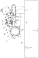
本発明の1つの実施の形態を図1~8にしたがって説明する。切断機1は、図1に示すように丸鋸盤であって、ベース21とソーヘッド10を有する。ソーヘッド10は、ベース21に設けられたレール26によってベース21に対して移動可能に取付けられる。ソーヘッド10は、ヘッド本体22とモータ25を有する。モータ25は、ベルト24とプーリーによってヘッド本体22の駆動軸11と力伝達可能に連結される。
One embodiment of the present invention will be described with reference to FIGS. As shown in FIG. 1, the cutting machine 1 is a circular saw and includes a base 21 and a saw head 10. The saw head 10 is movably attached to the base 21 by rails 26 provided on the base 21. The saw head 10 has a head body 22 and a motor 25. The motor 25 is connected to the drive shaft 11 of the head main body 22 by a belt 24 and a pulley so that force can be transmitted.
ヘッド本体22は、図1,2に示すように駆動軸11と裏カバー16と表カバー17を有する。駆動軸11に円盤状工具(鋸刃)2が装着される。駆動軸11がモータ25からの動力によって軸回転し、円盤状工具2が駆動軸11を中心に回転する。
The head body 22 has a drive shaft 11, a back cover 16, and a front cover 17 as shown in FIGS. A disk-shaped tool (saw blade) 2 is mounted on the drive shaft 11. The drive shaft 11 is rotated by power from the motor 25, and the disk-shaped tool 2 rotates around the drive shaft 11.
円盤状工具2は、図2,3に示すように円盤形状であって、中心領域に台金2a、外周領域に切断領域2bを有する。円盤状工具2が丸鋸の場合、切断領域2bに超硬合金、ダイヤモンド等の硬質材料からなる複数の刃が付けられる。円盤状工具2が切断砥石の場合、切断領域2bにダイヤモンド砥粒、超硬砥粒等が接着される。
The disk-shaped tool 2 has a disk shape as shown in FIGS. 2 and 3, and has a base metal 2a in the center area and a cutting area 2b in the outer peripheral area. When the disk-shaped tool 2 is a circular saw, a plurality of blades made of a hard material such as cemented carbide or diamond are attached to the cutting region 2b. When the disk-shaped tool 2 is a cutting grindstone, diamond abrasive grains, cemented carbide grains, etc. are bonded to the cutting area 2b.
円盤状工具2は、厚みが薄いことが好ましい。円盤状工具2が薄いことで切断時に生じる切り屑の量が少なくなる。また円盤状工具2が薄いことで切断時における切削抵抗が小さくなり、切断時に必要なエネルギーが小さくなる。しかし円盤状工具2が薄いことで、円盤状工具2の厚み方向の剛性が低くなり、円盤状工具2が切断時に軸方向にたわみやすくなる。これに対してソーヘッド10には、円盤状工具2の厚み方向(軸方向)のたわみを抑制する複数のガイド3,4が設けられる。
The disk-shaped tool 2 is preferably thin. Since the disk-shaped tool 2 is thin, the amount of chips generated during cutting is reduced. Further, since the disk-like tool 2 is thin, cutting resistance at the time of cutting is reduced, and energy required at the time of cutting is reduced. However, since the disk-shaped tool 2 is thin, the rigidity in the thickness direction of the disk-shaped tool 2 is reduced, and the disk-shaped tool 2 is easily bent in the axial direction when cutting. On the other hand, the saw head 10 is provided with a plurality of guides 3 and 4 that suppress the deflection in the thickness direction (axial direction) of the disk-shaped tool 2.
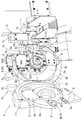
ソーヘッド10は、図3に示すように裏カバー16と表カバー17を有する。裏カバー16は、円盤状工具2を裏側から覆う。裏カバー16の下領域には、取付部材6を介してガイド3bが取付けられる。裏カバー16の上側領域には、ガイド4bが移動可能に取付けられる。
The saw head 10 has a back cover 16 and a front cover 17 as shown in FIG. The back cover 16 covers the disk-shaped tool 2 from the back side. The guide 3 b is attached to the lower region of the back cover 16 via the attachment member 6. A guide 4b is movably attached to the upper region of the back cover 16.
表カバー17は、図3に示すように裏カバー16に対して一端部が回転可能に連結される。表カバー17は、回転することで円盤状工具2の表側を覆う閉じ位置と、円盤状工具2の表側を開放する開き位置に移動する。表カバー17の下領域には、取付部材6を介してガイド3aが取付けられる。表カバー17の上側領域には、ガイド4aが移動可能に取付けられる。
The front cover 17 is rotatably connected at one end to the back cover 16 as shown in FIG. The front cover 17 rotates to move to a closed position that covers the front side of the disk-shaped tool 2 and an open position that opens the front side of the disk-shaped tool 2. A guide 3 a is attached to the lower region of the front cover 17 via the attachment member 6. A guide 4 a is movably attached to the upper region of the front cover 17.
裏カバー16と表カバー17には、図2,3に示すようにガイド3,4の距離を可変とする可変装置1aが設けられる。可変装置1aは、ガイド4をソーヘッド10に対して移動可能に保持する保持機構5と、ガイド4を切断時にワーク20の形状に応じて移動させる移動機構1bを有する。
As shown in FIGS. 2 and 3, the back cover 16 and the front cover 17 are provided with a variable device 1 a that makes the distance between the guides 3 and 4 variable. The variable device 1 a includes a holding mechanism 5 that holds the guide 4 so as to be movable with respect to the saw head 10, and a moving mechanism 1 b that moves the guide 4 according to the shape of the workpiece 20 when cutting.
保持機構5は、図3,7に示すようにアーム5aとレール5bと連結部材5cを有する。アーム5aは、板状で円弧状に延出する。レール5bには円弧状に延出する孔が形成され、孔にアーム5aが移動可能に挿入される。レール5bは、表カバー17および裏カバー16に取付けられて、アーム5aを円盤状工具2の回転と同心円上に移動可能に保持する。
The holding mechanism 5 includes an arm 5a, a rail 5b, and a connecting member 5c as shown in FIGS. The arm 5a is plate-shaped and extends in an arc shape. The rail 5b is formed with a hole extending in an arc shape, and the arm 5a is movably inserted into the hole. The rail 5b is attached to the front cover 17 and the back cover 16, and holds the arm 5a so as to be movable concentrically with the rotation of the disk-like tool 2.
レール5bは、図3,4,7に示すようにアーム5aを裏側から支持する裏部5b1と、アーム5aを表側から支持する表部5b2と、アーム5aを下側から支持する円弧状の下部5b3と、アーム5aを上側から覆う円弧状の上部5b4を有する。
As shown in FIGS. 3, 4, and 7, the rail 5 b includes a back portion 5 b 1 that supports the arm 5 a from the back side, a front portion 5 b 2 that supports the arm 5 a from the front side, and an arc-shaped lower portion that supports the arm 5 a from below. 5b3 and an arcuate upper portion 5b4 that covers the arm 5a from above.
アーム5aの基端部には、図3に示すように連結部材5cが取付けられる。連結部材5cは、アーム5aから円盤状工具2の径方向外方に延出する。表カバー17側と裏カバー16側に設けられる各連結部材5cは、表カバー17を閉じ位置にした際に取付具によって一体に接続される。これにより2つのアーム5aは、一体になってソーヘッド10に対して移動する。
A connecting member 5c is attached to the base end of the arm 5a as shown in FIG. The connecting member 5c extends from the arm 5a outward in the radial direction of the disk-shaped tool 2. The connecting members 5c provided on the front cover 17 side and the back cover 16 side are integrally connected by an attachment when the front cover 17 is set to the closed position. As a result, the two arms 5 a move together with respect to the saw head 10.
アーム5aの先端部には、図7に示すように隙間調整板9とガイド4が取付けられる。隙間調整板9とガイド4は、アーム5aの円盤状工具2側の面に取付けられる。隙間調整板9の厚みは、ガイド4と円盤状工具2の隙間の大きさによって決定される。
The gap adjusting plate 9 and the guide 4 are attached to the tip of the arm 5a as shown in FIG. The gap adjusting plate 9 and the guide 4 are attached to the surface of the arm 5a on the disk-like tool 2 side. The thickness of the gap adjusting plate 9 is determined by the size of the gap between the guide 4 and the disk-shaped tool 2.
ガイド3a,3b,4a,4bは、図3,4に示すように板状であって、円盤状工具2の台金2aの表面または裏面に対向するガイド面を有する。ガイド3a,3b,4a,4bと円盤状工具2の間には、小さい隙間が形成される。1対のガイド3a,3bは、対応する高さに設けられて対向し、ガイド3a,3bの間に円盤状工具2が設置される。1対のガイド3a,3bは、ワーク20よりも下側に設置され、ガイド3a,3bの先端は、円盤状工具2の切断領域2bの近傍にセットされる。
The guides 3 a, 3 b, 4 a, 4 b are plate-shaped as shown in FIGS. 3 and 4 and have a guide surface facing the front surface or the back surface of the base metal 2 a of the disk-shaped tool 2. A small gap is formed between the guides 3a, 3b, 4a, 4b and the disk-shaped tool 2. The pair of guides 3a and 3b are provided at corresponding heights and face each other, and the disk-shaped tool 2 is installed between the guides 3a and 3b. The pair of guides 3 a and 3 b are installed below the workpiece 20, and the tips of the guides 3 a and 3 b are set in the vicinity of the cutting area 2 b of the disk-shaped tool 2.
1対のガイド4a,4bは、図3,4に示すように対向する位置において各アーム5aに取付けられる。したがって1対のガイド4a,4bは、アーム5aとともに移動して常に対向した関係にある。1対のガイド4a,4bの間には円盤状工具2が設置される。1対のガイド4a,4bは、他の1対のガイド3a,3bよりも上方に位置する。1対のガイド4a,4bは、ワーク20を切断する前にワーク20と同じ高さに位置し、切断時に移動機構1bによって上方に移動する。これにより上下のガイド3,4の距離が変化する。
The pair of guides 4a and 4b are attached to the respective arms 5a at opposing positions as shown in FIGS. Therefore, the pair of guides 4a and 4b move together with the arm 5a and always have a facing relationship. A disk-shaped tool 2 is installed between the pair of guides 4a and 4b. The pair of guides 4a and 4b are located above the other pair of guides 3a and 3b. The pair of guides 4a and 4b are positioned at the same height as the workpiece 20 before cutting the workpiece 20, and are moved upward by the moving mechanism 1b at the time of cutting. As a result, the distance between the upper and lower guides 3 and 4 changes.
移動機構1bは、図3に示すように付勢体8と摺動部材7を有する。付勢体8は、空気圧を利用するシリンダを有し、裏カバー16の裏側に設けられる。付勢体8は、裏カバー16に設けられる連結部材5cに連結されて、連結部材5cを常に時計回りに付勢する。これによりアーム5aが付勢体の付勢力によって時計回りに付勢され、上のガイド4が下のガイド3に向けて付勢される。
The moving mechanism 1b has an urging member 8 and a sliding member 7 as shown in FIG. The urging body 8 has a cylinder that uses air pressure, and is provided on the back side of the back cover 16. The biasing body 8 is connected to a connecting member 5c provided on the back cover 16, and always biases the connecting member 5c clockwise. As a result, the arm 5 a is urged clockwise by the urging force of the urging body, and the upper guide 4 is urged toward the lower guide 3.
摺動部材7は、樹脂製であって、図4,5に示すように裏カバー16に取付けられたアーム5aに取付けられる。摺動部材7は、L字状であって下側部7aと前端部7bを一体に有する。下側部7aは、アーム5aの先端部の下側縁に取付けられてガイド4bよりも下方に突出する。前端部7bは、アーム5aの先端部の前縁に取付けられてガイド4bよりも前方(ワーク20の方向)に突出する。
The sliding member 7 is made of resin and is attached to the arm 5a attached to the back cover 16 as shown in FIGS. The sliding member 7 is L-shaped and integrally includes a lower side portion 7a and a front end portion 7b. The lower side portion 7a is attached to the lower edge of the tip portion of the arm 5a and protrudes downward from the guide 4b. The front end 7b is attached to the front edge of the tip of the arm 5a and projects forward (in the direction of the workpiece 20) from the guide 4b.
ガイド3は、図3に示すようにボルト18によって取付部材6に取付けられる。ボルト18には孔が形成され、取付部材6にはボルト18の孔に連通する連通孔が形成される。取付部材6の連通孔に空気、油あるいは空気と油の両方がミスト状態で供給される。連通孔とボルト18の孔を経て空気または油などがガイド3から円盤状工具2に向けて吹出される。これにより円盤状工具2とガイド3が当接した際に生じる摩擦抵抗が小さくなる。
The guide 3 is attached to the attachment member 6 with bolts 18 as shown in FIG. A hole is formed in the bolt 18, and a communication hole communicating with the hole of the bolt 18 is formed in the mounting member 6. Air, oil, or both air and oil are supplied to the communication hole of the mounting member 6 in a mist state. Air or oil or the like is blown out from the guide 3 toward the disk-shaped tool 2 through the communication hole and the hole of the bolt 18. As a result, the frictional resistance generated when the disk-shaped tool 2 and the guide 3 come into contact with each other is reduced.
ガイド4は、図3,7に示すようにボルト18によってアーム5aに取付けられる。アーム5aには、ボルト18の孔に連通する連通孔が形成される。アーム5aの連通孔に空気、油あるいは空気と油の両方が供給される。連通孔とボルト18の孔を経て空気または油がガイド4から円盤状工具2に向けて吹出される。これにより円盤状工具2とガイド4が当接した際に生じる摩擦抵抗が小さくなる。
The guide 4 is attached to the arm 5a by a bolt 18 as shown in FIGS. In the arm 5a, a communication hole communicating with the hole of the bolt 18 is formed. Air, oil, or both air and oil are supplied to the communication hole of the arm 5a. Air or oil is blown out from the guide 4 toward the disk-shaped tool 2 through the communication hole and the hole of the bolt 18. Thereby, the frictional resistance generated when the disk-shaped tool 2 and the guide 4 come into contact with each other is reduced.
ベース21には、図4に示すようにワーク20を保持するバイス装置1cが設けられる。バイス装置1cは、下側ジョー12、上側ジョー15、固定ジョー13、可動ジョー14を有する。下側ジョー12は、ベース21に固定され、ワーク20を下側から支持する。上側ジョー15は、ベース21に対して上下方向に移動可能に設けられて、ワーク20を下側ジョー12に向けて押す。固定ジョー13は、ベース21に固定され、ワーク20を一側方向から支持する。可動ジョー14は、ベース21に対して水平方向に移動可能に設けられ、ワーク20を固定ジョー13に向けて押す。
The base 21 is provided with a vise apparatus 1c for holding the workpiece 20 as shown in FIG. The vice apparatus 1 c includes a lower jaw 12, an upper jaw 15, a fixed jaw 13, and a movable jaw 14. The lower jaw 12 is fixed to the base 21 and supports the workpiece 20 from below. The upper jaw 15 is provided so as to be movable in the vertical direction with respect to the base 21 and pushes the workpiece 20 toward the lower jaw 12. The fixed jaw 13 is fixed to the base 21 and supports the workpiece 20 from one side direction. The movable jaw 14 is provided so as to be movable in the horizontal direction with respect to the base 21, and pushes the workpiece 20 toward the fixed jaw 13.
可動ジョー14には、図4,5に示すようにスリット14aと傾斜面14bが形成される。スリット14aには、円盤状工具2が挿入され、円盤状工具2がワーク20に到達することを許容する。傾斜面14bは、可動ジョー14の上端面に形成され、上方にかつ摺動部材7に向く。
As shown in FIGS. 4 and 5, the movable jaw 14 is formed with a slit 14a and an inclined surface 14b. The disk-shaped tool 2 is inserted into the slit 14 a and allows the disk-shaped tool 2 to reach the workpiece 20. The inclined surface 14 b is formed on the upper end surface of the movable jaw 14 and faces upward and toward the sliding member 7.
ワーク20は、図4に示すように長尺であり、丸棒、パイプ、板状等である。ワーク20は、例えば金属(鉄鋼、非鉄金属等)、樹脂などから成形される。切断機1には、ワーク20を長手方向に送出す送り装置19と、上側ジョー15と可動ジョー14を移動させる解除装置(図示省略)と、送り装置19と解除装置を制御する制御装置(図示省略)を有する。
The work 20 is long as shown in FIG. 4, and is a round bar, a pipe, a plate shape, or the like. The workpiece 20 is formed from, for example, metal (iron or steel, non-ferrous metal, etc.), resin, or the like. The cutting machine 1 includes a feeding device 19 for feeding the workpiece 20 in the longitudinal direction, a releasing device (not shown) for moving the upper jaw 15 and the movable jaw 14, and a control device (not shown) for controlling the feeding device 19 and the releasing device. (Omitted).
制御装置は、ワーク20から小片を切断した後に、解除装置を制御して上側ジョー15と可動ジョー14をワーク20から離し、送り装置19によってワーク20を所定長さ送出し、解除装置を制御して上側ジョー15と可動ジョー14をワーク20に押し当てる。これにより切断機1は、ワーク20から複数の小片を連続して切断し得る。
After the control device cuts the small piece from the work 20, the control device controls the release device to separate the upper jaw 15 and the movable jaw 14 from the work 20, and sends the work 20 by a predetermined length by the feed device 19 to control the release device. The upper jaw 15 and the movable jaw 14 are pressed against the workpiece 20. Thereby, the cutting machine 1 can cut | disconnect a several small piece from the workpiece | work 20 continuously.
切断機1によってワーク20を切断する場合は、図3に示すようにワーク20をバイス装置1cにセットする。駆動軸11に円盤状工具2をセットし、表カバー17を閉じ、1対の連結部材5cを連結する。円盤状工具2を回転させ、ソーヘッド10を送り装置23によってワーク20に向けて移動させる。
When cutting the workpiece 20 by the cutting machine 1, the workpiece 20 is set in the vice apparatus 1c as shown in FIG. The disk-shaped tool 2 is set on the drive shaft 11, the front cover 17 is closed, and the pair of connecting members 5c are connected. The disk-shaped tool 2 is rotated, and the saw head 10 is moved toward the workpiece 20 by the feeding device 23.
図5,6に示すように摺動部材7が可動ジョー14の傾斜面14bに当たり、傾斜面14bに沿って上方に移動する。円盤状工具2がワーク20に当たり、ワーク20を徐々に切断する。ワーク20の切断開始時では、上下のガイド3,4の距離は比較的小さい。
As shown in FIGS. 5 and 6, the sliding member 7 hits the inclined surface 14b of the movable jaw 14, and moves upward along the inclined surface 14b. The disk-shaped tool 2 hits the workpiece 20 and gradually cuts the workpiece 20. At the start of cutting the workpiece 20, the distance between the upper and lower guides 3 and 4 is relatively small.
次に図5,6に示すように摺動部材7がワーク20の外周面に当たり、ワーク20の外周面に沿って上方に移動する。これによりアーム5aが図3の付勢体8の付勢力に抗して移動し、上のガイド4が上方に移動する。上のガイド4は、ワーク20の外表面からの距離を所定量に保持しつつワーク20の外形に沿って移動する。そのためガイド4は、ワーク20に当たることなく、ワーク20の外周面から略所定の距離にて移動する。
Next, as shown in FIGS. 5 and 6, the sliding member 7 hits the outer peripheral surface of the work 20 and moves upward along the outer peripheral surface of the work 20. As a result, the arm 5a moves against the urging force of the urging body 8 of FIG. 3, and the upper guide 4 moves upward. The upper guide 4 moves along the outer shape of the workpiece 20 while maintaining a predetermined distance from the outer surface of the workpiece 20. Therefore, the guide 4 moves from the outer peripheral surface of the workpiece 20 at a substantially predetermined distance without hitting the workpiece 20.
上下のガイド3,4の距離は、図5,6に示すように切断時に徐々に大きくなり、上下のガイド3,4間にワーク20が入ることを許容する。円盤状工具2は、切断領域2bがワーク20を貫通することでワーク20を切断する。
The distance between the upper and lower guides 3 and 4 gradually increases during cutting as shown in FIGS. 5 and 6 and allows the workpiece 20 to enter between the upper and lower guides 3 and 4. The disk-shaped tool 2 cuts the workpiece 20 when the cutting region 2 b penetrates the workpiece 20.
円盤状工具2は、摩耗等により切削力の表側と裏側のバランスが崩れることで軸方向に振れ得る。円盤状工具2が軸方向に振れた場合、台金2aがガイド3,4に当たって円盤状工具2の軸方向の振れがガイド3,4によって規制される。
The disk-shaped tool 2 can swing in the axial direction by breaking the balance between the front side and the back side of the cutting force due to wear or the like. When the disk-shaped tool 2 is swung in the axial direction, the base metal 2 a hits the guides 3 and 4, and the wobbling of the disk-shaped tool 2 in the axial direction is restricted by the guides 3 and 4.
ワーク20から小片を切断した後、制御装置が送り装置23を制御してソーヘッド10を元の位置に戻す。アーム5aが付勢体8によって移動し、上のガイド4が下のガイド3に向けて移動する。制御装置が解除装置と送り装置19を制御して、ワーク20が長手方向に移動し、ワーク20がバイス装置1cによって再度保持される。ワーク20を前述と同様に切断して、ワーク20から複数の小片を切断する。ワーク20の小片は、例えば鍛造品を成形する際の材料に使用される。
After cutting a small piece from the workpiece 20, the control device controls the feeding device 23 to return the saw head 10 to its original position. The arm 5a is moved by the biasing body 8, and the upper guide 4 is moved toward the lower guide 3. The control device controls the release device and the feeding device 19 so that the workpiece 20 moves in the longitudinal direction, and the workpiece 20 is held again by the vice device 1c. The workpiece 20 is cut in the same manner as described above, and a plurality of small pieces are cut from the workpiece 20. The small piece of the workpiece 20 is used as a material for forming a forged product, for example.
切断機1によって実験を試みた。実験では、円盤状工具2としてチップソー(外径300mm、刃厚1.1mm、台金厚0.8mm、孔径40mm、刃数60)、ワーク20としてアルミニウム合金(JIS規格表示のA6061)、直径70mmを準備した。切削条件は、1250rpm、送り0.025mm/刃、ガイド3,4と台金2aのクリアランスを0.01mmに設定した。
An experiment was attempted with the cutting machine 1. In the experiment, a tip saw (outer diameter 300 mm, blade thickness 1.1 mm, base metal thickness 0.8 mm, hole diameter 40 mm, number of blades 60) is used as the disk-shaped tool 2, and an aluminum alloy (JIS standard A6061) is used as the work 20, diameter 70 mm. Prepared. Cutting conditions were set to 1250 rpm, feed 0.025 mm / blade, and the clearance between the guides 3 and 4 and the base metal 2 a to 0.01 mm.
切断機1でワーク20を切断する場合、上のガイド4が上方に移動し、上下のガイド3,4の間隔が60mmから98mmの間を移動した。切断機1でワーク20を切断した後にワーク20の切断面を測定した。その結果、ワーク20の切断面の曲がりは0.057mmであった。比較の実験としてガイド3,4の間隔を100mmに保持してワーク20を切断した。比較実験におけるワーク20の切断面の曲がりは、0.094mmであった。したがって上下のガイド3,4の間隔を可変にすることでワーク20の切断面を平滑に切断し得ることがわかった。
When cutting the workpiece 20 with the cutting machine 1, the upper guide 4 moved upward, and the distance between the upper and lower guides 3, 4 moved between 60 mm and 98 mm. After cutting the workpiece 20 with the cutting machine 1, the cut surface of the workpiece 20 was measured. As a result, the bending of the cut surface of the workpiece 20 was 0.057 mm. As a comparative experiment, the workpiece 20 was cut while the distance between the guides 3 and 4 was maintained at 100 mm. The curvature of the cut surface of the workpiece 20 in the comparative experiment was 0.094 mm. Therefore, it was found that the cut surface of the workpiece 20 can be cut smoothly by making the distance between the upper and lower guides 3 and 4 variable.
図8は、実験結果であり、円盤状工具2の剛性と上下のガイド3,4間の距離の関係を示す。実験では、上下のガイド3,4の距離を所定の距離に設定し、円盤状工具2にガイド3,4に向けて力を加え、円盤状工具2のガイド3とガイド4の中間の位置における軸方向(厚み方向)の剛性(1mm変形させるための力)を測定し、図8に測定結果をまとめた。図8に示すようにガイド3,4の距離が小さいほど円盤状工具2の剛性が大きく、円盤状工具2が変形し難いことがわかる。したがってガイド3,4の距離を可能な限り小さくしつつワーク20を切断することが好ましいことがわかる。そのため本形態の切断機1によると、ガイド3,4の距離を比較的小さくしつつワーク20を切断し得るため、ワーク20を精度良く切断し得ることがわかる。
FIG. 8 shows the experimental results and shows the relationship between the rigidity of the disk-shaped tool 2 and the distance between the upper and lower guides 3 and 4. In the experiment, the distance between the upper and lower guides 3 and 4 is set to a predetermined distance, a force is applied to the disc-shaped tool 2 toward the guides 3 and 4, and the disc-shaped tool 2 is positioned between the guide 3 and the guide 4. The axial direction (thickness direction) rigidity (force for deforming 1 mm) was measured, and the measurement results are summarized in FIG. As shown in FIG. 8, it can be seen that the smaller the distance between the guides 3 and 4, the greater the rigidity of the disk-shaped tool 2, and the disk-shaped tool 2 is difficult to deform. Therefore, it can be seen that it is preferable to cut the workpiece 20 while making the distance between the guides 3 and 4 as small as possible. Therefore, according to the cutting machine 1 of this embodiment, since the workpiece 20 can be cut while the distance between the guides 3 and 4 is relatively small, it can be seen that the workpiece 20 can be cut with high accuracy.
一方、従来のようにガイドを固定する場合、例えば上下のガイドを固定する場合、上下のガイドの距離を少なくともワーク20が通過し得る距離以上に設定する必要がある。しかもワーク20の直径のばらつきを考慮して、上下のガイドの距離をワーク20の直径よりも大きく設定する必要がある。そのためガイドを固定する切断機では、円盤状工具2の剛性が低くなり、ワーク20の切断面を所定角度(通常は直角)にすることが容易でなく、かつ切断面を平滑に形成することが容易でない。
On the other hand, when the guide is fixed as in the prior art, for example, when the upper and lower guides are fixed, it is necessary to set the distance between the upper and lower guides to be at least the distance that the workpiece 20 can pass through. Moreover, it is necessary to set the distance between the upper and lower guides to be larger than the diameter of the workpiece 20 in consideration of variations in the diameter of the workpiece 20. For this reason, in the cutting machine for fixing the guide, the rigidity of the disk-shaped tool 2 is lowered, it is not easy to make the cutting surface of the workpiece 20 a predetermined angle (usually a right angle), and the cutting surface can be formed smoothly. Not easy.
以上のように切断機1は、図1,2に示すように円盤状工具2とソーヘッド10と2対のガイド3,4と可変装置1aを有する。円盤状工具2は、2面を有する。ソーヘッド10は、円盤状工具2を回転可能に保持する。2対のガイド3,4は、ソーヘッド10に設けられ、各対のガイド3,4が円盤状工具2の2面に対面する。可変装置1aは、ワーク20が円盤状工具2によって切断される時にワーク20が2対のガイド3,4の間を通過するように2対のガイド3,4の距離を可変させる。
As described above, the cutting machine 1 includes the disk-shaped tool 2, the saw head 10, the two pairs of guides 3 and 4, and the variable device 1a as shown in FIGS. The disk-shaped tool 2 has two surfaces. The saw head 10 holds the disk-shaped tool 2 rotatably. Two pairs of guides 3, 4 are provided on the saw head 10, and each pair of guides 3, 4 faces two surfaces of the disk-shaped tool 2. The variable device 1 a varies the distance between the two pairs of guides 3 and 4 so that the workpiece 20 passes between the two pairs of guides 3 and 4 when the workpiece 20 is cut by the disk-shaped tool 2.
したがって切断時に円盤状工具2が回転しつつワーク20を切削し、ワーク20が2対のガイド3,4間を通る。2対のガイド3,4は、円盤状工具2の軸方向のたわみ(挽き曲り)をワーク20の両側(上下)において規制する。また2対のガイド3,4の距離は、可変であるため、2対のガイド3,4をワーク20の形状に応じて可変にし得る。そのためワーク20が2対のガイド3,4間を通る際に2対のガイド3,4の距離を大きくしてワーク20が2対のガイド3,4間を通るようにし得る。
Therefore, the workpiece 20 is cut while the disk-like tool 2 is rotating at the time of cutting, and the workpiece 20 passes between the two pairs of guides 3 and 4. The two pairs of guides 3 and 4 restrict the deflection (grinding) in the axial direction of the disk-shaped tool 2 on both sides (up and down) of the workpiece 20. Further, since the distance between the two pairs of guides 3 and 4 is variable, the two pairs of guides 3 and 4 can be made variable according to the shape of the workpiece 20. Therefore, when the workpiece 20 passes between the two pairs of guides 3, 4, the distance between the two pairs of guides 3, 4 can be increased so that the workpiece 20 passes between the two pairs of guides 3, 4.
一方、従来の切断機では、ワーク20が2対のガイドの間を通るように最初から2対のガイドの距離が固定される。そのためワーク20の最大直径に合わせてガイドの距離が十分に大きく設定される。したがって従来の切断機に比べて本形態は、2対のガイド3,4の距離を小さくし得る。2対のガイド3,4の距離を小さくすることで切削位置とガイド3,4の距離を短く出来る。そのため円盤状工具2の軸方向のたわみ、とりわけワーク20を切断する領域である2対のガイド間における円盤状工具の軸方向のたわみを抑制し得る。これにより円盤状工具によってワークの切断面を所定角度に精度良くかつ平滑に切断し得る。
On the other hand, in the conventional cutting machine, the distance between the two pairs of guides is fixed from the beginning so that the workpiece 20 passes between the two pairs of guides. Therefore, the distance of the guide is set sufficiently large according to the maximum diameter of the workpiece 20. Therefore, the present embodiment can reduce the distance between the two pairs of guides 3 and 4 as compared with the conventional cutting machine. By reducing the distance between the two pairs of guides 3 and 4, the distance between the cutting position and the guides 3 and 4 can be shortened. Therefore, it is possible to suppress the axial deflection of the disk-shaped tool 2, particularly the axial deflection of the disk-shaped tool between two pairs of guides, which are regions where the workpiece 20 is cut. Thereby, the cut surface of the workpiece can be cut accurately and smoothly at a predetermined angle by the disk-shaped tool.
可変装置1aは、図3に示すようにさらに保持機構5と移動機構1bを有する。保持機構5は、1対のガイド4をソーヘッド10に対して移動可能に保持する。移動機構1bは、1対のガイド4を円盤状工具2によって切断されるワーク20の形状に応じて移動させる。したがって切断時にワーク20が2対のガイド3,4の間を通過し、2対のガイド3,4の距離がワーク20の形状に応じて変化する。これにより2対のガイド3,4は、切断時においてワーク20に対して比較的近くに位置し得る。
The variable device 1a further includes a holding mechanism 5 and a moving mechanism 1b as shown in FIG. The holding mechanism 5 holds the pair of guides 4 so as to be movable with respect to the saw head 10. The moving mechanism 1b moves the pair of guides 4 according to the shape of the workpiece 20 cut by the disk-like tool 2. Accordingly, the workpiece 20 passes between the two pairs of guides 3 and 4 during cutting, and the distance between the two pairs of guides 3 and 4 changes according to the shape of the workpiece 20. Thus, the two pairs of guides 3 and 4 can be positioned relatively close to the workpiece 20 at the time of cutting.
移動機構1bは、図3に示すようにさらに付勢体8と摺動部材7を有する。付勢体8は、2対のガイド3,4の距離を小さくする方向に1対のガイド4を付勢する。摺動部材7は、1対のガイド4に設けられて円盤状工具2によって切断されるワーク20に当接して摺動する。したがって2対のガイド3,4は、切断前に付勢体8によって距離が一番小さくなる。切断時に2対のガイド3,4の間をワーク20が通ることで摺動部材7がワーク20に当たる。付勢体8の付勢力に抗して摺動部材7とともにガイド4が移動して、2対のガイド3,4の距離が大きくなる。そのため2対のガイド3,4の距離は、ワーク20の形状に応じて変化する。
The moving mechanism 1b further includes an urging body 8 and a sliding member 7 as shown in FIG. The urging body 8 urges the pair of guides 4 in a direction that reduces the distance between the two pairs of guides 3 and 4. The sliding member 7 slides in contact with a workpiece 20 provided on the pair of guides 4 and cut by the disk-shaped tool 2. Therefore, the distance between the two pairs of guides 3 and 4 is minimized by the biasing body 8 before cutting. When the workpiece 20 passes between the two pairs of guides 3 and 4 at the time of cutting, the sliding member 7 comes into contact with the workpiece 20. The guide 4 moves together with the sliding member 7 against the urging force of the urging body 8, and the distance between the two pairs of guides 3 and 4 increases. Therefore, the distance between the two pairs of guides 3 and 4 changes according to the shape of the workpiece 20.
保持機構5は、図3に示すようにさらにアーム5aとレール5bを有する。アーム5aには1対のガイド4が装着される。レール5bは、アーム5aが円盤状工具2の中心の同心円において移動するようにアーム5aを保持する。したがってガイド4が保持機構5によって円盤状工具2と同心円状に移動する。そのためガイド4が切断領域2bに沿って移動するようにセットされる。これによりガイド4が常に切断領域2bの近傍位置において円盤状工具2の軸方向の振れを抑制し得る。かくして円盤状工具2の軸方向の振れを効果的に抑制し得る。
The holding mechanism 5 further has an arm 5a and a rail 5b as shown in FIG. A pair of guides 4 is attached to the arm 5a. The rail 5b holds the arm 5a so that the arm 5a moves in a concentric circle at the center of the disk-shaped tool 2. Therefore, the guide 4 is moved concentrically with the disk-like tool 2 by the holding mechanism 5. Therefore, the guide 4 is set so as to move along the cutting area 2b. Thereby, the guide 4 can always suppress the axial deflection of the disk-shaped tool 2 at a position in the vicinity of the cutting region 2b. Thus, the axial deflection of the disk-shaped tool 2 can be effectively suppressed.
本発明の形態を上記構造を参照して説明したが、本発明の目的を逸脱せずに多くの交代、改良、変更が可能であることは当業者であれば明らかである。したがって本発明の形態は、添付された請求項の精神と目的を逸脱しない全ての交代、改良、変更を含み得る。例えば本発明の形態は、前記特別な構造に限定されず、下記のように変更が可能である。
Although the embodiments of the present invention have been described with reference to the above structure, it will be apparent to those skilled in the art that many substitutions, improvements, and changes can be made without departing from the object of the present invention. Accordingly, aspects of the invention may include all alterations, modifications, and changes that do not depart from the spirit and scope of the appended claims. For example, the form of the present invention is not limited to the special structure, and can be modified as follows.
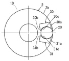
図1~8に示す切断機に代えて図9~13に示す切断機でも良い。図9~13に示す切断機は、1対のガイド30と他の1対のガイド31と図示省略の可変装置を有する。各対のガイド30,31は、それぞれソーヘッド10に対して移動可能に設けられる。可変装置は、保持機構と移動機構を有する。保持機構は、ガイド30,31をソーヘッド10に対して移動可能に保持する。移動機構は、ガイド30,31を切断時にワーク20の形状に応じて移動させる。
The cutting machines shown in FIGS. 9 to 13 may be used instead of the cutting machines shown in FIGS. 9 to 13 includes a pair of guides 30, another pair of guides 31, and a variable device (not shown). Each pair of guides 30 and 31 is provided so as to be movable with respect to the saw head 10. The variable device has a holding mechanism and a moving mechanism. The holding mechanism holds the guides 30 and 31 so as to be movable with respect to the saw head 10. The moving mechanism moves the guides 30 and 31 according to the shape of the workpiece 20 when cutting.
図9~13に示すガイド30,31には、第一張出部30a,31aと第二張出部30b,31bと凹部30c,31cが形成される。第一張出部30a,31aは、円盤状工具2の切断領域2b側のガイド30,31の一端部から他のガイド30,31に向けて張出す。第二張出部30b,31bは、円盤状工具2の中心側のガイド30,31の一端部から他のガイド30,31に向けて張出す。凹部30c,31cは、ワーク20の外形に対応する形状である。凹部30c,31cは、ワーク20の形状よりも大きく、例えばワーク20の半径よりも大きい曲率半径を有する。これにより凹部30c,31c間にワーク20が収容される。
9 to 13 are formed with first projecting portions 30a and 31a, second projecting portions 30b and 31b, and recessed portions 30c and 31c. The first projecting portions 30 a and 31 a project from one end of the guides 30 and 31 on the cutting area 2 b side of the disc-shaped tool 2 toward the other guides 30 and 31. The second projecting portions 30 b and 31 b project from one end portion of the guides 30 and 31 on the center side of the disk-shaped tool 2 toward the other guides 30 and 31. The recesses 30 c and 31 c have a shape corresponding to the outer shape of the workpiece 20. The recesses 30 c and 31 c have a radius of curvature larger than the shape of the workpiece 20, for example, larger than the radius of the workpiece 20. Thereby, the workpiece | work 20 is accommodated between the recessed parts 30c and 31c.
図9~11に示すようにソーヘッド10をワーク20に向けて移動させると、ガイド30がワーク20の形状に合わせて上方に移動する。ガイド31が下方に移動し、ガイド30,31間の距離が徐々に大きくなる。図12,13に示すようにワーク20の中心が第一張出部30a,31aを結んだ線を越えた後は、ガイド30がワーク20の形状に合わせて下方に移動し,ガイド31が上方に移動する。これによりガイド30,31間の距離が徐々に小さくなる。
9 to 11, when the saw head 10 is moved toward the workpiece 20, the guide 30 moves upward in accordance with the shape of the workpiece 20. The guide 31 moves downward, and the distance between the guides 30 and 31 gradually increases. As shown in FIGS. 12 and 13, after the center of the workpiece 20 exceeds the line connecting the first projecting portions 30a and 31a, the guide 30 moves downward in accordance with the shape of the workpiece 20, and the guide 31 moves upward. Move to. As a result, the distance between the guides 30 and 31 gradually decreases.
図9~13に示す切断機でワーク20を切断した場合のワーク20の切込み量と円盤状工具2のたわみ量を解析し、図15の各点34に示した。図15に示すたわみ量は、円盤状工具2の先端部でかつガイド30,31間における最大のたわみ量である。図9に示す切断機の比較のために図14に示す切断機を想定した。図14に示す切断機の切込み量と円盤状工具2のたわみ量を解析し、図15の各点35に示した。
The cutting amount of the workpiece 20 and the deflection amount of the disk-shaped tool 2 when the workpiece 20 was cut by the cutting machine shown in FIGS. 9 to 13 were analyzed, and indicated by each point 34 in FIG. The amount of deflection shown in FIG. 15 is the maximum amount of deflection between the guides 30 and 31 at the tip of the disk-shaped tool 2. For comparison with the cutting machine shown in FIG. 9, the cutting machine shown in FIG. 14 was assumed. The amount of cutting of the cutting machine shown in FIG. 14 and the amount of deflection of the disk-shaped tool 2 were analyzed and indicated by points 35 in FIG.
図14の切断機は、1対のガイド32と他の1対のガイド33を有する。各対のガイド32,33がそれぞれソーヘッド10に移動不能に取付けられる。ガイド32,33の距離は、想定するワーク20の最大直径よりも大きくなるように固定される。したがってガイド32,33の距離は、切断時において常に一定に保持される。
14 has a pair of guides 32 and another pair of guides 33. Each pair of guides 32 and 33 is attached to the saw head 10 so as not to move. The distance between the guides 32 and 33 is fixed to be larger than the assumed maximum diameter of the workpiece 20. Therefore, the distance between the guides 32 and 33 is always kept constant during cutting.
図15に示すように同一切込み量におけるたわみ量は、図14に示す切断機における各点35に比べて図9に示す切断機における各点34が小さい。切込み量の最初と最後の時点における点34と点35は、いずれもたわみ量がゼロである。たわみ量のピーク値は、各点35に比べて各点34において小さい。ピーク値が持続する時間は、各点35に比べて各点34において短い。切込み初期のたわみ量の上昇率は、各点35に比べて各点34において小さく、その差が大きい。
As shown in FIG. 15, the deflection amount at the same cutting amount is smaller at each point 34 in the cutting machine shown in FIG. 9 than in each point 35 in the cutting machine shown in FIG. 14. The point 34 and the point 35 at the first time point and the last time point of the cut amount are both zero. The peak value of the deflection amount is smaller at each point 34 than at each point 35. The time for which the peak value lasts is shorter at each point 34 than at each point 35. The rate of increase in the amount of deflection at the beginning of cutting is smaller at each point 34 than at each point 35, and the difference is large.
挽き曲り量は、切込み量とたわみ量の積分から求められ、図15において領域で現される。したがって挽き曲り量は、各点34で現される領域が各点35で現される領域よりも小さく、約4分の1になる。すなわち図9の切断機における挽き曲り量は、図15の切断機における挽き曲り量よりも小さい。主要因は、図15から切込み初期におけるたわみ量の上昇率の差であることがわかる。
The grinding amount is obtained from the integration of the cutting amount and the deflection amount, and is represented by a region in FIG. Therefore, the amount of grinding is smaller than the area represented by each point 35 in the area represented by each point 34, and is about a quarter. That is, the amount of bending in the cutting machine of FIG. 9 is smaller than the amount of bending in the cutting machine of FIG. It can be seen from FIG. 15 that the main factor is the difference in the rate of increase in the amount of deflection at the beginning of cutting.
可変装置1aは、図3に示すように上のガイド4を保持する保持機構5と上のガイド4を移動させる移動機構1bを有していても良い。可変装置1aは、保持機構5と移動機構1bに代えてあるいは加えて下のガイド3を移動可能に保持する保持機構と、下のガイド3を移動させる移動機構を有していても良い。
The variable device 1a may have a holding mechanism 5 for holding the upper guide 4 and a moving mechanism 1b for moving the upper guide 4 as shown in FIG. The variable device 1a may have a holding mechanism that movably holds the lower guide 3 in place of or in addition to the holding mechanism 5 and the moving mechanism 1b, and a moving mechanism that moves the lower guide 3.
移動機構1bは、付勢体8と摺動部材7を有していても良い。代わりに移動機構1bは、アーム5aを移動させる駆動機構と、駆動機構を制御する制御装置を有していても良い。制御装置は、予め入力されたワークの情報あるいはワークの形状を測定するセンサからの検知信号に基づいて駆動機構を制御する。これによりアーム5aとともにガイド4をワーク20の形状に応じて移動させ得る。
The moving mechanism 1 b may have an urging body 8 and a sliding member 7. Instead, the moving mechanism 1b may include a drive mechanism that moves the arm 5a and a control device that controls the drive mechanism. The control device controls the drive mechanism on the basis of workpiece information input in advance or a detection signal from a sensor that measures the shape of the workpiece. Thereby, the guide 4 can be moved according to the shape of the workpiece 20 together with the arm 5a.
移動機構1bは、ガイド4をワーク20の外形に倣って移動させても良い。あるいはガイド4をワーク20の外形の概略形状に沿って移動させても良い。あるいはガイド4をワーク20の形状に緩やかに追従して移動させても良い。
The moving mechanism 1b may move the guide 4 following the outer shape of the workpiece 20. Alternatively, the guide 4 may be moved along the outline shape of the workpiece 20. Alternatively, the guide 4 may be moved slowly following the shape of the workpiece 20.
保持機構5は、ガイド4を円盤状工具2と同心円上を移動可能に保持しても良い。あるいは保持機構5は、ガイド4を円盤状工具2と同心円に近い曲線または直線上において移動可能に保持しても良い。
The holding mechanism 5 may hold the guide 4 so as to be movable concentrically with the disk-like tool 2. Alternatively, the holding mechanism 5 may hold the guide 4 so as to be movable on a curve or straight line that is concentric with the disk-like tool 2.
付勢体8は、空気圧によって付勢力を生じるシリンダを有していても良い。あるいは付勢体8は、弾性力によって付勢力を生じるばねまたはゴムでも良い。あるいは付勢体8は、ガス圧によって付勢力を生じるガススプリングでも良い。
The urging body 8 may have a cylinder that generates an urging force by air pressure. Alternatively, the biasing body 8 may be a spring or rubber that generates a biasing force by an elastic force. Alternatively, the biasing body 8 may be a gas spring that generates a biasing force by gas pressure.
円盤状工具2は、外周縁に切断領域2bを有していても良い。あるいは円盤状工具2は、内周縁に切断領域を有していても良い。
The disk-shaped tool 2 may have a cutting area 2b on the outer periphery. Or the disk-shaped tool 2 may have a cutting area | region in an inner periphery.
切断機1は、1対のガイド3,4を2対有していても良い。あるいは切断機1は、1対のガイドを3対以上有していても良い。
The cutting machine 1 may have two pairs of guides 3 and 4. Alternatively, the cutting machine 1 may have three or more pairs of guides.
Claims (4)
- 円盤状工具を回転させて前記円盤状工具によってワークを切断する切断機であって、
2面を有する円盤状工具と、前記円盤状工具を回転可能に保持するソーヘッドと、前記ソーヘッドに設けられる2対のガイドであって前記各対のガイドが前記円盤状工具の前記2面に対面する前記2対のガイドと、前記円盤状工具によって切断される時に前記ワークが前記2対のガイドの間を通過するように前記2対のガイドの距離を可変させる可変装置を有する切断機。 A cutting machine that rotates a disk-shaped tool to cut a workpiece with the disk-shaped tool,
A disk-shaped tool having two surfaces, a saw head for rotatably holding the disk-shaped tool, and two pairs of guides provided on the saw head, each pair of guides facing the two surfaces of the disk-shaped tool A cutting machine having the two pairs of guides and a variable device that varies a distance between the two pairs of guides so that the workpiece passes between the two pairs of guides when being cut by the disk-shaped tool. - 請求項1に記載の切断機であって、
前記可変装置は、さらに少なくとも1対の前記ガイドを前記ソーヘッドに対して移動可能に保持する保持機構と、前記少なくとも1対のガイドを前記円盤状工具によって切断される時に前記ワークの形状に応じて移動させる移動機構を有する切断機。 The cutting machine according to claim 1,
The variable device further includes a holding mechanism that movably holds at least one pair of the guides with respect to the saw head, and a shape of the workpiece when the at least one pair of guides is cut by the disk-shaped tool. A cutting machine having a moving mechanism for moving. - 請求項2に記載の切断機であって、
前記移動機構は、さらに前記2対のガイドの距離を小さくする方向に前記少なくとも1対のガイドを付勢する付勢体と、前記少なくとも1対のガイドに設けられて前記円盤状工具によって切断される時に前記ワークに当接して摺動する摺動部材を有する切断機。 The cutting machine according to claim 2,
The moving mechanism is further provided with an urging body for urging the at least one pair of guides in a direction to reduce the distance between the two pairs of guides, and is cut by the disk-shaped tool provided on the at least one pair of guides. A cutting machine having a sliding member that slides in contact with the workpiece when moving. - 請求項2または3に記載の切断機であって、
前記保持機構は、前記少なくとも1対の前記ガイドが装着されるアームと、前記アームが前記円盤状工具中心の同心円において移動するように前記アームを保持するレールを有する切断機。 The cutting machine according to claim 2 or 3,
The holding mechanism includes an arm on which the at least one pair of the guides is mounted, and a rail that holds the arm so that the arm moves in a concentric circle at the center of the disk-shaped tool.
Priority Applications (4)
| Application Number | Priority Date | Filing Date | Title |
|---|---|---|---|
| EP12817349.9A EP2737968B1 (en) | 2011-07-27 | 2012-06-19 | Cutting machine |
| CN201280037061.4A CN103796782B (en) | 2011-07-27 | 2012-06-19 | Cutting machine |
| JP2013525625A JP5996536B2 (en) | 2011-07-27 | 2012-06-19 | Cutting machine |
| KR1020147004060A KR101879608B1 (en) | 2011-07-27 | 2012-06-19 | Cutting machine |
Applications Claiming Priority (2)
| Application Number | Priority Date | Filing Date | Title |
|---|---|---|---|
| JP2011-164117 | 2011-07-27 | ||
| JP2011164117 | 2011-07-27 |
Publications (1)
| Publication Number | Publication Date |
|---|---|
| WO2013015042A1 true WO2013015042A1 (en) | 2013-01-31 |
Family
ID=47600901
Family Applications (1)
| Application Number | Title | Priority Date | Filing Date |
|---|---|---|---|
| PCT/JP2012/065589 WO2013015042A1 (en) | 2011-07-27 | 2012-06-19 | Cutting machine |
Country Status (6)
| Country | Link |
|---|---|
| EP (1) | EP2737968B1 (en) |
| JP (2) | JP5996536B2 (en) |
| KR (1) | KR101879608B1 (en) |
| CN (1) | CN103796782B (en) |
| TW (1) | TWI538755B (en) |
| WO (1) | WO2013015042A1 (en) |
Cited By (1)
| Publication number | Priority date | Publication date | Assignee | Title |
|---|---|---|---|---|
| JP2017104929A (en) * | 2015-12-09 | 2017-06-15 | 株式会社アマダホールディングス | Circular saw machine |
Citations (4)
| Publication number | Priority date | Publication date | Assignee | Title |
|---|---|---|---|---|
| JPH02239901A (en) * | 1989-03-14 | 1990-09-21 | Fuji Kogyo Kk | Bracing device for circular sawing machine |
| JPH0340019U (en) * | 1989-08-25 | 1991-04-17 | ||
| JPH07227714A (en) * | 1994-02-17 | 1995-08-29 | Kitagawa Denki:Kk | Circular saw cutter |
| JP2004338081A (en) | 2003-04-08 | 2004-12-02 | Keuro Besitz Gmbh & Co Edv Dienstleistungs Kg | Circular sawing machine |
Family Cites Families (7)
| Publication number | Priority date | Publication date | Assignee | Title |
|---|---|---|---|---|
| US2941451A (en) * | 1956-05-02 | 1960-06-21 | Hughes Aircraft Co | Cutter support |
| DE2447147C3 (en) * | 1974-10-03 | 1986-08-21 | Jägers, Leopold, 5350 Euskirchen | Machine for cold sawing steel plates with horizontal feed |
| JPH03208519A (en) * | 1990-01-11 | 1991-09-11 | Amada Co Ltd | Method and device for automatically setting position of saw blade guide in band saw machine |
| US5398578A (en) * | 1992-11-12 | 1995-03-21 | Andersen; Jens H. | Breakaway guide |
| JPH08155731A (en) * | 1994-12-08 | 1996-06-18 | Amada Co Ltd | Automatic positioning method for traveling side saw-tooth guide arm in band saw machine and its device |
| CN2810841Y (en) * | 2005-04-11 | 2006-08-30 | 长沙中联重工科技发展股份有限公司 | Hard alloy circular saw bench |
| CN201744734U (en) * | 2010-05-27 | 2011-02-16 | 张家港和升数控机床制造有限公司 | Sawing device |
-
2012
- 2012-06-19 WO PCT/JP2012/065589 patent/WO2013015042A1/en unknown
- 2012-06-19 EP EP12817349.9A patent/EP2737968B1/en active Active
- 2012-06-19 CN CN201280037061.4A patent/CN103796782B/en active Active
- 2012-06-19 JP JP2013525625A patent/JP5996536B2/en active Active
- 2012-06-19 KR KR1020147004060A patent/KR101879608B1/en active IP Right Grant
- 2012-06-26 TW TW101122741A patent/TWI538755B/en active
-
2016
- 2016-07-12 JP JP2016137283A patent/JP6169760B2/en active Active
Patent Citations (4)
| Publication number | Priority date | Publication date | Assignee | Title |
|---|---|---|---|---|
| JPH02239901A (en) * | 1989-03-14 | 1990-09-21 | Fuji Kogyo Kk | Bracing device for circular sawing machine |
| JPH0340019U (en) * | 1989-08-25 | 1991-04-17 | ||
| JPH07227714A (en) * | 1994-02-17 | 1995-08-29 | Kitagawa Denki:Kk | Circular saw cutter |
| JP2004338081A (en) | 2003-04-08 | 2004-12-02 | Keuro Besitz Gmbh & Co Edv Dienstleistungs Kg | Circular sawing machine |
Non-Patent Citations (1)
| Title |
|---|
| See also references of EP2737968A4 * |
Cited By (3)
| Publication number | Priority date | Publication date | Assignee | Title |
|---|---|---|---|---|
| JP2017104929A (en) * | 2015-12-09 | 2017-06-15 | 株式会社アマダホールディングス | Circular saw machine |
| WO2017098979A1 (en) * | 2015-12-09 | 2017-06-15 | 株式会社アマダホールディングス | Circular sawing machine in which wobble of circular saw blade can be suppressed |
| US10875107B2 (en) | 2015-12-09 | 2020-12-29 | Amada Holdings Co., Ltd. | Circular saw machine capable of suppressing runout of circular saw blade |
Also Published As
| Publication number | Publication date |
|---|---|
| JP6169760B2 (en) | 2017-07-26 |
| KR20140060291A (en) | 2014-05-19 |
| KR101879608B1 (en) | 2018-07-19 |
| JPWO2013015042A1 (en) | 2015-02-23 |
| CN103796782A (en) | 2014-05-14 |
| EP2737968A4 (en) | 2015-03-11 |
| EP2737968B1 (en) | 2020-03-25 |
| EP2737968A1 (en) | 2014-06-04 |
| JP5996536B2 (en) | 2016-09-21 |
| TW201318739A (en) | 2013-05-16 |
| JP2016193489A (en) | 2016-11-17 |
| CN103796782B (en) | 2016-01-06 |
| TWI538755B (en) | 2016-06-21 |
Similar Documents
| Publication | Publication Date | Title |
|---|---|---|
| JP3455224B2 (en) | Accessories for angle grinders | |
| US20140144972A1 (en) | Friction processing tool, and friction processing apparatus and friction processing method using the same | |
| US20190375033A1 (en) | Sawing machine for bevel cuts | |
| JP6169760B2 (en) | Circular saw machine and cutting method using the circular saw machine | |
| JP3177599U (en) | Circular member end grinding machine | |
| TW200708387A (en) | Cutting machine | |
| JP4369279B2 (en) | Circular saw board | |
| CN105081820B (en) | It is a kind of to configure the quick lathe for compressing and unclamping fixture | |
| JP4687461B2 (en) | Work cutting device and work cutting method | |
| JP4148166B2 (en) | Contact detection device | |
| JP5685276B2 (en) | Saw blade back taper processing equipment | |
| CN108890411A (en) | A kind of saw blade grinder | |
| US9527147B2 (en) | Saw blade indexing assembly | |
| JP2774448B2 (en) | Band sawing machine bending prevention device | |
| CN113305655A (en) | Diamond cutter machining device | |
| JP5433489B2 (en) | Cutting blade position adjusting jig and cutting blade position adjusting method | |
| CN209919014U (en) | Grinding mechanism of grinder | |
| US20160059331A1 (en) | Sawing machine | |
| TW201444644A (en) | Cutting machines and control methods of the same | |
| CN219151747U (en) | Sawing machine feed feedback device | |
| KR100460542B1 (en) | apparatus and processing method for long production | |
| CN215942358U (en) | Magnetic steel grinding device | |
| JP3119632U (en) | Grinding device for rotary blade of brush cutter | |
| JP4454850B2 (en) | Machine for machining workpieces with saw teeth | |
| JP2884080B1 (en) | Cutting edge forming method and cutting edge forming device for multi-blade grinding tool |
Legal Events
| Date | Code | Title | Description |
|---|---|---|---|
| 121 | Ep: the epo has been informed by wipo that ep was designated in this application |
Ref document number: 12817349 Country of ref document: EP Kind code of ref document: A1 |
|
| ENP | Entry into the national phase |
Ref document number: 2013525625 Country of ref document: JP Kind code of ref document: A |
|
| NENP | Non-entry into the national phase |
Ref country code: DE |
|
| ENP | Entry into the national phase |
Ref document number: 20147004060 Country of ref document: KR Kind code of ref document: A |