EP3387950B1 - Ensemble de rails de glissement - Google Patents
Ensemble de rails de glissement Download PDFInfo
- Publication number
- EP3387950B1 EP3387950B1 EP17201601.6A EP17201601A EP3387950B1 EP 3387950 B1 EP3387950 B1 EP 3387950B1 EP 17201601 A EP17201601 A EP 17201601A EP 3387950 B1 EP3387950 B1 EP 3387950B1
- Authority
- EP
- European Patent Office
- Prior art keywords
- rail
- feature
- assembly
- slide rail
- along
- Prior art date
- Legal status (The legal status is an assumption and is not a legal conclusion. Google has not performed a legal analysis and makes no representation as to the accuracy of the status listed.)
- Active
Links
- 238000013016 damping Methods 0.000 claims description 60
- 230000000903 blocking effect Effects 0.000 claims description 57
- 230000000694 effects Effects 0.000 claims description 9
- 230000003993 interaction Effects 0.000 claims description 7
- 230000004044 response Effects 0.000 claims description 4
- 238000010586 diagram Methods 0.000 description 22
- 238000000034 method Methods 0.000 description 6
- 230000008569 process Effects 0.000 description 6
- 238000003466 welding Methods 0.000 description 3
- 238000013459 approach Methods 0.000 description 1
- 230000001419 dependent effect Effects 0.000 description 1
- 238000011161 development Methods 0.000 description 1
- 230000018109 developmental process Effects 0.000 description 1
- 230000007246 mechanism Effects 0.000 description 1
- 230000001360 synchronised effect Effects 0.000 description 1
Images


Classifications
-
- A—HUMAN NECESSITIES
- A47—FURNITURE; DOMESTIC ARTICLES OR APPLIANCES; COFFEE MILLS; SPICE MILLS; SUCTION CLEANERS IN GENERAL
- A47B—TABLES; DESKS; OFFICE FURNITURE; CABINETS; DRAWERS; GENERAL DETAILS OF FURNITURE
- A47B88/00—Drawers for tables, cabinets or like furniture; Guides for drawers
- A47B88/40—Sliding drawers; Slides or guides therefor
- A47B88/44—Sequencing or synchronisation of drawer slides or functional units
- A47B88/443—Successive movement of rails within drawer slides, i.e. at least one rail element is not moving during the movement of other elements
-
- A—HUMAN NECESSITIES
- A47—FURNITURE; DOMESTIC ARTICLES OR APPLIANCES; COFFEE MILLS; SPICE MILLS; SUCTION CLEANERS IN GENERAL
- A47B—TABLES; DESKS; OFFICE FURNITURE; CABINETS; DRAWERS; GENERAL DETAILS OF FURNITURE
- A47B88/00—Drawers for tables, cabinets or like furniture; Guides for drawers
- A47B88/40—Sliding drawers; Slides or guides therefor
- A47B88/44—Sequencing or synchronisation of drawer slides or functional units
- A47B88/447—Simultaneous movement of rails within drawer slides, i.e. with a coordination of movement with all rail elements moving at the same time
-
- A—HUMAN NECESSITIES
- A47—FURNITURE; DOMESTIC ARTICLES OR APPLIANCES; COFFEE MILLS; SPICE MILLS; SUCTION CLEANERS IN GENERAL
- A47B—TABLES; DESKS; OFFICE FURNITURE; CABINETS; DRAWERS; GENERAL DETAILS OF FURNITURE
- A47B88/00—Drawers for tables, cabinets or like furniture; Guides for drawers
- A47B88/40—Sliding drawers; Slides or guides therefor
- A47B88/473—Braking devices, e.g. linear or rotational dampers or friction brakes; Buffers; End stops
- A47B88/477—Buffers; End stops
-
- A—HUMAN NECESSITIES
- A47—FURNITURE; DOMESTIC ARTICLES OR APPLIANCES; COFFEE MILLS; SPICE MILLS; SUCTION CLEANERS IN GENERAL
- A47B—TABLES; DESKS; OFFICE FURNITURE; CABINETS; DRAWERS; GENERAL DETAILS OF FURNITURE
- A47B88/00—Drawers for tables, cabinets or like furniture; Guides for drawers
- A47B88/40—Sliding drawers; Slides or guides therefor
- A47B88/49—Sliding drawers; Slides or guides therefor with double extensible guides or parts
-
- F—MECHANICAL ENGINEERING; LIGHTING; HEATING; WEAPONS; BLASTING
- F16—ENGINEERING ELEMENTS AND UNITS; GENERAL MEASURES FOR PRODUCING AND MAINTAINING EFFECTIVE FUNCTIONING OF MACHINES OR INSTALLATIONS; THERMAL INSULATION IN GENERAL
- F16C—SHAFTS; FLEXIBLE SHAFTS; ELEMENTS OR CRANKSHAFT MECHANISMS; ROTARY BODIES OTHER THAN GEARING ELEMENTS; BEARINGS
- F16C29/00—Bearings for parts moving only linearly
- F16C29/12—Arrangements for adjusting play
-
- A—HUMAN NECESSITIES
- A47—FURNITURE; DOMESTIC ARTICLES OR APPLIANCES; COFFEE MILLS; SPICE MILLS; SUCTION CLEANERS IN GENERAL
- A47B—TABLES; DESKS; OFFICE FURNITURE; CABINETS; DRAWERS; GENERAL DETAILS OF FURNITURE
- A47B2210/00—General construction of drawers, guides and guide devices
- A47B2210/0002—Guide construction for drawers
- A47B2210/0064—Guide sequencing or synchronisation
- A47B2210/007—Three slide synchronisation
-
- A—HUMAN NECESSITIES
- A47—FURNITURE; DOMESTIC ARTICLES OR APPLIANCES; COFFEE MILLS; SPICE MILLS; SUCTION CLEANERS IN GENERAL
- A47B—TABLES; DESKS; OFFICE FURNITURE; CABINETS; DRAWERS; GENERAL DETAILS OF FURNITURE
- A47B88/00—Drawers for tables, cabinets or like furniture; Guides for drawers
- A47B88/40—Sliding drawers; Slides or guides therefor
- A47B88/473—Braking devices, e.g. linear or rotational dampers or friction brakes; Buffers; End stops
-
- A—HUMAN NECESSITIES
- A47—FURNITURE; DOMESTIC ARTICLES OR APPLIANCES; COFFEE MILLS; SPICE MILLS; SUCTION CLEANERS IN GENERAL
- A47B—TABLES; DESKS; OFFICE FURNITURE; CABINETS; DRAWERS; GENERAL DETAILS OF FURNITURE
- A47B88/00—Drawers for tables, cabinets or like furniture; Guides for drawers
- A47B88/40—Sliding drawers; Slides or guides therefor
- A47B88/49—Sliding drawers; Slides or guides therefor with double extensible guides or parts
- A47B88/493—Sliding drawers; Slides or guides therefor with double extensible guides or parts with rollers, ball bearings, wheels, or the like
-
- A—HUMAN NECESSITIES
- A47—FURNITURE; DOMESTIC ARTICLES OR APPLIANCES; COFFEE MILLS; SPICE MILLS; SUCTION CLEANERS IN GENERAL
- A47B—TABLES; DESKS; OFFICE FURNITURE; CABINETS; DRAWERS; GENERAL DETAILS OF FURNITURE
- A47B88/00—Drawers for tables, cabinets or like furniture; Guides for drawers
- A47B88/50—Safety devices or the like for drawers
- A47B88/53—Safety devices or the like for drawers preventing unintentional closing, e.g. anti-pinch devices
-
- F—MECHANICAL ENGINEERING; LIGHTING; HEATING; WEAPONS; BLASTING
- F16—ENGINEERING ELEMENTS AND UNITS; GENERAL MEASURES FOR PRODUCING AND MAINTAINING EFFECTIVE FUNCTIONING OF MACHINES OR INSTALLATIONS; THERMAL INSULATION IN GENERAL
- F16C—SHAFTS; FLEXIBLE SHAFTS; ELEMENTS OR CRANKSHAFT MECHANISMS; ROTARY BODIES OTHER THAN GEARING ELEMENTS; BEARINGS
- F16C2314/00—Personal or domestic articles, e.g. household appliances such as washing machines, dryers
- F16C2314/70—Furniture
- F16C2314/72—Drawers
Definitions
- the present invention is related to a slide rail assembly having two rails capable of moving synchronously.
- a slide rail assembly comprises a first rail and a second rail movable relative to the first rail.
- the slide rail assembly further comprises a third rail movably mounted between the first rail and the second rail for forming a so-called three-section slide rail assembly.
- US patent number US 7,357,468 B2 discloses a locating structure for a slide assembly, which comprises an outer rail (6), a middle rail (4) and an inner rail (5).
- a linking member (1) and a locating member (2) are pivotally connected to the middle rail (4) by a pivoting pin (13), and an elastic member (3) is fixed to the middle rail (4) for providing an elastic force to the linking member (1) and the locating member (2) .
- the middle rail (4) and the inner rail (5) can be synchronously pulled out.
- the middle rail (4) and the inner rail (5) are moved a predetermined distance, the middle rail (4) can be hooked to a retaining portion (611) of the outer rail (6) to be temporarily held at a position.
- the case is provided for reference.
- US patent application number US 2008/0197758 A1 describes a staging lock (22) being movably mounted to an intermediate member (16), and having a follower tab (58) and a lock tab (66).
- the follower tab (58) engages a cam form (106) on the cabinet member (14) and moves the staging lock (22) from closed position to an open position.
- the lock tab (66) engages a staging lock catch (114) on the chassis member (18) to secure the chassis member (18) in a fully retracted position within the intermediate member (16).
- the chassis member (18) may extend from within the intermediate member (16) .
- a rear lock (24) retains the intermediate member (16) in a fully extended position until the chassis member (18) is fully retracted within the intermediate member (16).
- the cabinet member (14), the intermediate member (16), and the chassis member (18) comprise a three-section slide rail assembly.
- the purpose of the staging lock (22) is to engage two rail members such that they move synchronously.
- the purpose of the rear lock (24) is to prevent the intermediate member (16) from being moved relative to the cabinet member (14).
- US patent number US 9,538,845 B1 describes a synchronous mechanism of a slide rail that includes a first hooked bracket, a second hooked bracket, an inner hook set and an outer hook set.
- the first hooked bracket and the second hooked bracket are installed on a middle rail, and the inner hook set is installed on an inner rail, and the outer hook set is installed on an outer rail.
- the present invention aims at providing a slide rail assembly having two rails capable of moving synchronously.
- the claimed slide rail assembly comprises a first rail, a second rail, a third rail, a contact member, a synchronization member, a fastening member, a blocking feature, a working member, a base and a releasing member.
- the second rail is movable relative to the first rail.
- the third rail is movably mounted between the first rail and the second rail.
- the contact member is mounted to the first rail.
- the synchronization member is pivoted to the third rail by a first shaft member.
- the fastening member is pivoted to the third rail by a second shaft member.
- the blocking feature is fixed to the third rail.
- the working member is pivoted to the second rail.
- the base has an elastic part for providing an elastic force to the working member.
- the releasing member is operatively connected to the working member and configured to deflect the working member to be no longer blocked by the blocking feature .
- the releasing member comprises a releasing part, a driving part and an extension part.
- the driving part is configured to drive the working member to move.
- the extension part is connected between the releasing part and the driving part and substantially arranged along a longitudinal direction of the second rail.
- the fastening member When the third rail is moved from the first predetermined position to a second predetermined position along the opening direction, the fastening member is configured to be fastened to the contact member, in order to prevent the third rail from being retracted relative to the first rail along a retracted direction.
- the working member is blocked by the blocking feature in order to prevent the second rail from being moved from the open position along the retracted direction.
- the second rail is configured to disengage the fastening member from the contact member, for allowing the third rail to be moved relative to the first rail along the retracted direction.
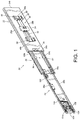
- a slide rail assembly 20 comprises a first rail 22 and a second rail 24 according to the present invention.
- the slide rail assembly 20 further comprises a third rail 26 movably mounted between the first rail 22 and the second rail 24 for extending a traveling distance of the second rail 24 relative to the first rail 22.
- the first rail 22 comprises a first wall 28a, a second wall 28b and a side wall 30 connected between the first wall 28a and the second wall 28b.
- a first passage 32 is defined by the first wall 28a, the second wall 28b and the side wall 30 of the first rail 22.
- the first rail 22 has a front part 34a and a rear part 34b.
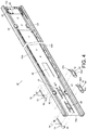
- the slide rail assembly 20 further comprises a blocking structure 36, a contact member 38 and at least one damping device 40.
- the blocking structure 36 is mounted to the side wall 30 of the first rail 22.
- the blocking structure 36 can be fixed to the first rail 22 by riveting, screwing or welding; or, the blocking structure 36 can be integrally formed on the first rail 22. Therefore, the blocking structure 36 can be seen as a portion of the first rail 22.
- the blocking structure is a protruded wall, but the present invention is not limited thereto.
- the blocking structure 36 can be a recessed structure (or a hole).
- the blocking structure 36 is adjacent to the front part 34a of the first rail 22.
- the contact member 38 is mounted to the side wall 30 of the first rail 22.
- the contact member 38 can be fixed to the first rail 22 by riveting, screwing or welding; or, the contact member 38 can be integrally formed on the first rail 22. Therefore, the contact member 38 can be seen as a portion of the first rail 22.
- the contact member 38 is away from the front part 34a of the first rail 22. That is, the contact member 38 and the blocking structure 36 are located at different positions on the first rail 22.
- the contact member 38 comprises a guiding part 42 and an abutting part 44 adjacent to the guiding part 42. Wherein, the guiding part 42 has an inclined surface or an arc surface.
- the at least one damping device 40 is mounted to the first rail 22.
- each of the damping devices 40 is located between the blocking structure 36 and the contact member 38.
- the side wall 30 of the first rail 22 has an opening 46. Two opposite sides of the opening 46 are provided with a first side wall 48a and a second side wall 48b respectively.
- the damping device 40 is configured to provide a damping effect.
- the damping device 40 comprises a first damping part 50 and a second damping part 52.
- the first damping part 50 can be a cylinder
- the second damping part 52 can be a rod.
- the cylinder contains a damping medium and/or an elastic object therein, and the rod is configured to be extended from or retracted into the cylinder.
- the first damping part 50 can be a rod
- the second damping part 52 can be a cylinder, but the present invention is not limited to the aforementioned embodiments.
- the slide rail assembly 20 further comprises a holding base 54, a first component 56 and a second component 58.
- the holding base 54 is located within the opening 46 between the first side wall 48a and the second side wall 48b.
- the holding base 54 is mounted to the first rail 22.
- the holding base 54 can be fixed to the first rail 22 by engaging, riveting or screwing.
- the holding base 54 provides mounting structures 60 for mounting the damping device 40.
- the first component 56 and the second component 58 are movably mounted to the first rail 22.
- each of the first component 56 and the second component 58 has at least one sliding feature 62.
- the at least one sliding feature 62 can be a sliding groove slidable within the opening 46 of the first rail 22, so as to allow the first component 56 and the second component 58 to move relative to the first rail 22.
- the first component 56 is located between the first side wall 48a and the first damping part 50
- the second component 58 is located between the second side wall 48b and the second damping part 52.
- the third rail 26 is mounted to the first passage 32 of the first rail 22 and movable relative to the first rail 22.
- the third rail 26 comprises a first wall 64a, a second wall 64b and a side wall 66 connected between the first wall 64a and a second wall 64b.
- a second passage 68 is defined by the first wall 64a, the second wall 64b and the side wall 66.
- the third rail 26 has a front part 70a and a rear part 70b.
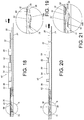
- the slide rail assembly 20 further comprises a synchronization member 72 and a fastening member 74.
- the synchronization member 72 is movably mounted to the third rail 26.
- the third rail 26 has a first elongated hole 75.
- the synchronization member 72 is pivoted to the third rail 26 by a first shaft member 76.
- the synchronization member 72 is configured to be deflected between the first rail 22 and the second rail 24 through the first elongated hole 75.
- the synchronization member 72 has a first part 78 and a second part 80 respectively located at two sides of the first shaft member 76.
- the slide rail assembly 20 further comprises a first elastic member 82 configured to apply an elastic force to the synchronization member 72.
- the first elastic member 82 has a main body part 82a and an elastic leg 82b connected to the main body part 82a, and the elastic leg 82b is configured to apply an elastic force to the second part 80.
- the third rail 26 has a second elongated hole 83.
- the fastening member 74 is pivoted to the third rail 26 by a second shaft member 84.
- the fastening member 74 is configured to be deflected between the first rail 22 and the second rail 24 through the second elongated hole 83.
- the fastening member 74 has a first section 86 and a second section 88 respectively located at two sides of the second shaft member 84.
- the slide rail assembly 20 further comprises a second elastic member 90 configured to apply an elastic force to the fastening member 74.
- the second elastic member 90 has a main body part 90a and an elastic leg 90b connected to the main body part 90a, and the elastic leg 90b is configured to apply an elastic force to the second section 88.
- the synchronization member 72 and the fastening member 74 are adjacent to the rear part 70b of the third rail 26 and arranged at different positions on the third rail 26 along a longitudinal direction of the third rail 26.
- the third rail 26 comprises a first pushing feature 92, a second pushing feature 94 and a blocking feature 96.
- a predetermined distance is defined between the first pushing feature 92 and the second pushing feature 94, and both of the first pushing feature 92 and the second pushing feature 94 are protruded structures in the present embodiment.
- the first pushing feature 92 and the second pushing feature 94 are configured to face toward the side wall 30 of the first rail 22.
- the blocking feature 96 is configured to face toward a side wall 100 of the second rail 24.
- the blocking feature 96 can be a protrusion.
- an additional component is fixed to the third rail 26, and the component has the blocking feature 96 adjacent to the front part 70a of the third rail 26.
- the blocking feature 96 can be seen as a portion of the third rail 26, but the present invention is not limited thereto.
- the blocking feature 96 can be integrally formed on the third rail 26.
- the second rail 24 is mounted to the second passage 68 of the third rail 26 and movable relative to the third rail 26.
- the second rail 24 comprises a first wall 98a, a second wall 98b and the side wall 100 connected between the first wall 98a and the second wall 98b.
- the second rail 24 has a front part 101a and a rear part 101b.
- the slide rail assembly 20 further comprises a locking member 102.
- the slide rail assembly 20 further comprises an operating member 104, a working member 106 and a releasing member 108.
- the locking member 102 When the slide rail assembly 20 is in a retracted state, the locking member 102 is configured to abut against the blocking structure 36 of the first rail 22.
- the locking member 102 can be operatively mounted to the second rail 24, and the locking member 102 is adjacent to the front part 101a of the second rail 24.
- the locking member 102 is movably mounted to the second rail 24.
- the locking member 102 is pivoted to the second rail 24.
- the slide rail assembly 20 further comprises a supporting structure 110 attached to the second rail 24.
- the supporting structure 110 comprises a main body part 112, at least one ear part 114 and an elastic part 116.
- the main body part 112 can be connected to the side wall 100 of the second rail 24 by riveting, screwing or welding.
- the at least one ear part 114 is substantially perpendicularly connected to the main body part 112.
- the elastic part 116 is tiled relative to the main body part 112 and configured to provide an elastic force to the locking member 102.
- the locking member 102 comprises a body part 118, a guiding feature 120 and a locking part 150.
- the body part 118 is pivoted to the at least one ear part 114 of the supporting structure 110 by a pin member 126, and the guiding feature 120 and the locking part 150 are respectively located at two sides of the pin member 126.
- the guiding feature 120 has an inclined surface or an arc surface.
- the guiding feature 120 is configured to face toward the side wall 30 of the first rail 22 through a through hole 128 of the second rail 24.
- the locking member 102 further comprises at least one shoulder part 122 and at least one first feature 124.
- the at least one shoulder part 122 is extended from the body part 118 and adjacent to the guiding feature 120.
- the at least one shoulder part 122 is located at a position corresponding to at least one limiting part 130 of the second rail 24, wherein the at least one limiting part 130 is protruded relative to the side wall 100 of the second rail 24.
- the at least one first feature 124 is connected to the body part 118 and adjacent to the locking part 150.
- the at least one first feature 124 is located at a position corresponding to at least one hole 131 of the second rail 24.
- the operating member 104 is configured to be operated to move the locking member 102.
- the operating member 104 is movable relative to the second rail 24.
- the operating member 104 has at least one elongated hole 132.
- the operating member 104 is movably mounted to the second rail 24 by arranging at least one connecting member 134 to pass through a portion of the at least one elongated hole 132.
- the operating member 104 comprises at least one second feature 136 configured to interactively work with the at least one first feature 124 of the locking member 102.
- one of the at least one second feature 136 and the at least one first feature 124 has an inclined surface or an arc surface.
- the slide rail assembly 20 further comprises at least one auxiliary elastic member 138 configured to apply an elastic force to the operating member 104, in order to hold the operating member 104 in a predetermined operating state.
- the working member 106 is movably mounted to the second rail 24.
- the working member 106 is pivoted to the side wall 100 of the second rail 24.
- the slide rail assembly 20 further comprises a base 140 having an elastic part 142 for providing an elastic force to the working member 106, in order to hold the working member 106 in a predetermined state relative to the second rail 24.
- the releasing member 108 is operatively connected to the working member 106.
- the releasing member 108 comprises a releasing part 144, a driving part 146 and an extension part 148.
- the releasing part 144 is connected to the operating member 104.
- the driving part 146 is configured to drive the working member 106 to move.
- the extension part 148 is connected between the releasing part 144 and the driving part 146, and the extension part 148 is substantially arranged along a longitudinal direction of the second rail 24.
- the slide rail assembly 20 is in a retracted state. Specifically, in the retracted state, the second rail 24 and the third rail 26 are retracted relative to the first rail 22.
- the locking part 150 of the locking member 102 is configured to abut against a first side S1 of the blocking structure 36 of the first rail 22, in order to prevent the second rail 24 from being moved relative to the first rail 22 from the retracted position R along a first direction (such as an opening direction), so as to ensure that the slide rail assembly 20 is in the retracted state.
- the operating member 104 is extended beyond the front part 101a of the second rail 24 for allowing a user to operate the operating member 104 conveniently.
- the locking part 150 of the locking member 102 is held to abut against the blocking structure 36 of the first rail 22 in response to the elastic force of the elastic part 116 of the supporting structure 110.
- the elastic part 116 of the supporting structure 110 is configured to elastically support the locking member 102.
- the first pushing feature 92 and the second pushing feature 94 of the third rail 26 are respectively located at two sides of the damping device 40.
- the second pushing feature 94 can temporarily abut against the second damping part 52 of the damping device 40 through the second component 58, such that the second damping part 52 is retracted relative to the first damping part 50.
- the elastic leg 82b of the first elastic member 82 applies an elastic force to the second part 80 of the synchronization member 72, such that the second part 80 of the synchronization member 72 leans toward the first rail 22, and the first part 78 of the synchronization member 72 is engaged with an engaging feature 152 of the second rail 24 (such as engaged with a wall of a hole or groove on the second rail 24);
- the elastic lag 90b of the second elastic member 90 applies an elastic force to the second section 88 of the fastening member 74, such that the second section 88 of the fastening member 74 leans toward the first rail 22, and the first section 86 of the fastening member 74 leans toward the second rail 24.
- the user in order to operate the slide rail assembly 20 to be no longer in the retracted state, the user can operate the locking member 102 to move the locking part 150 of the locking member 102 to no longer abut against the first side S1 of the blocking structure 36 of the first rail 22.
- the user can apply a force F to the operating member 104 to move the operating member 104 relative to the locking member 102, so as to drive the locking member 102 to move.
- the locking part 150 of the locking member 102 is disengaged from the blocking structure 36.
- the operating member 104 can easily drive the locking member 102 to deflect, in order to disengage the locking part 150 of the locking member 102 from the first side S1 of the blocking structure 36.
- the locking member 102 when the locking member 102 is operated to deflect, the elastic part 116 of the supporting structure 110 is elastically bent for accumulating an elastic force, and the first feature 124 of the locking member 102 approaches to the hole 131 of the second rail 24.
- the shoulder part 122 of the locking member 102 when the locking member 102 is operated to deflect, the shoulder part 122 of the locking member 102 is configured to abut against the limiting part 130 of the second rail 24.
- the second rail 24 and the third rail 26 are movable relative to the first rail 22 from the retracted position along the first direction D1.
- the second rail 24 and the third rail 26 can be synchronously moved relative to the first rail 22 along the first direction D1 through the synchronization member 72.
- the second rail 24 and the third rail 26 can be synchronously moved.
- the third rail 26 is no longer synchronously moved with the second rail 24 due to interaction between the synchronization member 72 and the contact member 38 of the first rail 22.
- the second part 80 of the synchronization member 72 contacts the guiding part 42 of the contact member 38, such that the synchronization member 72 is deflected accordingly, and the first part 78 of the synchronization member 72 is disengaged from the engaging feature 152 of the second rail 24. Therefore, the third rail 26 is no longer synchronously moved with the second rail 24 along the first direction D1.
- at least one of the guiding part 42 and the second part 80 of the synchronization member 72 has an inclined surface or an arc surface, in order to assist the synchronization member 72 in deflecting.
- the second rail 24 and the third rail 26 when the second rail 24 and the third rail 26 are no longer synchronously moved, the second rail 24 and the third rail 26 can be further moved relative to the first rail 22 along the first direction D1 independently (or individually) . Wherein, when the third rail 26 is further moved from the first predetermined position P1 along the first direction D1, the second section 88 of the fastening member 74 contacts a portion of the contact member 38 of the first rail 22, such as the guiding part 42.
- first pushing feature 92 of the third rail 26 can push the first damping part 50 of the damping device 40 through the first component 56, such that the second damping part 52 is gradually retracted relative to the first damping part 50 for providing a damping effect to the third rail 26 and/or the second rail 24.
- the user can aware that the third rail 26 is going to be in a fully extended state relative to the first rail 22 according to the damping effect.
- At least one of the guiding part 42 and the second section 88 of the fastening member 74 has an inclined surface or an arc surface, in order to assist the second section 88 of the fastening member 74 in crossing the guiding part 42 of the contact member 38.
- the elastic leg 90b of the second elastic member 90 accumulates an elastic force.
- the first pushing feature 92 of the third rail 26 further pushes the first damping part 50 of the damping device 40 through the first component 56, such that the second damping part 52 can be further retracted relative to the first damping part 50.
- the fastening member 74 is temporarily fastened to the contact member 38 (such as the second section 88 of the fastening member 74 being temporarily fastened to the abutting part 44 of the contact member 38) in order to prevent the third rail 26 from being retracted relative to the first rail 22 along a second direction D2 (such as a retracted direction).
- the first pushing feature 92 of the third rail 26 can further push the first damping part 50 of the damping device 40 through the first component 56, such that the second damping part can be further retracted relative to the first damping part 50 to the limit.
- the second rail 24 can be further moved relative to the third rail 26 and/or the first rail 22 along the first direction D1 to an open position E (or an extension position), so as to fully open the slide rail assembly 20.
- the working member 106 is blocked by the blocking feature 96 of the third rail 26, in order to prevent the second rail 24 from being moved from the open position E along the second direction D2 (such as the retracted direction).
- the user can apply the force F to the releasing member 108 or the operating member 104 in order to move the working member 106 to be no longer blocked by the blocking feature 96.
- the releasing member 108 is driven to deflect the working member 106 through the driving part 146, such that the working member 106 is no longer blocked by the blocking feature 96.
- the second rail 24 is movable relative to the third rail 26 and/or the first rail 22 from the open position E along the second direction D2.
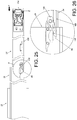
- a portion of the second rail 24 (such as the rear part 101b of the second rail 24) is configured to contact the first section 86 of the fastening member 74 (please refer to FIG. 31 ) .
- the rear part 101b of the second rail 24 can drive the fastening member 74 through the first section 86 in order to disengage the second section 88 of the fastening member 74 from the abutting part 44 of the contact member 38, such that the third rail 26 is movable relative to the first rail 22 along the second direction D2.
- the second pushing feature 94 of the third rail 26 pushes the second damping part 52 of the damping device 40 through the second component 58 for providing a damping effect to the third rail 26 and/or the second rail 24.
- the user can aware that the third rail 26 is going to be in a fully retracted state relative to the first rail 22 according to the damping effect.
- the guiding feature 120 of the locking member 102 is configured to abut against a second side S2 of the blocking structure 36 of the first rail 22.
- the locking member 102 is deflected by the blocking structure 36, so as to allow the guiding feature 120 of the locking member 102 to cross the second side S2 of the blocking structure 36.
- the blocking structure 36 also has a guiding feature 154. Through interaction between the guiding features 120, 154 (such as two inclined surfaces or arc surfaces abutting against each other), the locking member 102 can easily cross the second side S2 of the blocking structure 36.
- the locking part 150 of the locking member 102 abuts against the first side S1 of the blocking structure 36 of the first rail 22 once again in response to the elastic force of the elastic part 116 of the supporting structure 110. That is, the second rail 24 (and the third rail 36) can be held at the retracted position R relative to the first rail 22 once again (as shown in FIG. 7 and FIG. 8 ).
- the slide rail assembly 20 being in the retracted state is provided.
- the slide rail assembly of the present invention is characterized in that:
Landscapes
- Engineering & Computer Science (AREA)
- General Engineering & Computer Science (AREA)
- Mechanical Engineering (AREA)
- Drawers Of Furniture (AREA)
- Seats For Vehicles (AREA)
Claims (11)
- Ensemble rail coulissant (20), comprenant :un premier rail (22) ;un deuxième rail (24) mobile par rapport au premier rail (22) ;un troisième rail (26) monté mobile entre le premier rail (22) et le deuxième rail (24),le troisième rail (26) présentant un premier trou allongé (75) et un deuxième trou allongé (83) ;caractérisé par :un élément de contact (38) monté sur le premier rail (22) ;un élément de synchronisation (72) pivoté vers le troisième rail (26) par un premier élément d'arbre (76) et conçu pour être dévié entre le premier rail (22) et le deuxième rail (24) à travers le premier trou allongé (75) ; etun élément de fixation (74) pivoté vers le troisième rail (26) par un deuxième élément d'arbre (84) et conçu pour être dévié entre le premier rail (22) et le deuxième rail (24) à travers le deuxième trou allongé (83) ;où, lorsque le deuxième rail (24) est déplacé à partir d'une position rétractée dans le sens de l'ouverture, le troisième rail (26) est déplacé de manière synchrone avec le deuxième rail (24) par rapport au premier rail (22) dans le sens de l'ouverture par l'intermédiaire de l'élément de synchronisation (72) et, lorsque le deuxième rail (24) et le troisième rail (26) sont déplacés vers une première position prédéterminée, le troisième rail (26) n'est plus déplacé de manière synchrone avec le deuxième rail (24) en raison de l'interaction entre l'élément de synchronisation (72) et l'élément de contact (38) ;où, lorsque le troisième rail (26) est déplacé à partir de la première position prédéterminée vers une deuxième position prédéterminée dans le sens de l'ouverture, l'élément de fixation (74) est conçu pour être fixé à l'élément de contact (38), afin d'empêcher la rétraction du troisième rail (26) par rapport au premier rail (22) dans le sens rétracté.
- Ensemble rail coulissant selon la revendication 1, caractérisé en ce que l'élément de synchronisation (72) présente une première partie (78) et une deuxième partie (80) respectivement situées sur deux côtés du premier élément d'arbre (76), la première partie (78) étant conçue pour venir en prise avec le deuxième rail (24) ; lorsque le deuxième rail (24) et le troisième rail (26) sont déplacés vers la première position prédéterminée, la deuxième partie (80) entre en contact avec l'élément de contact (38) pour dévier l'élément de synchronisation (72) afin de séparer la première partie (78) du deuxième rail (24), l'ensemble rail de coulissement (20) comprenant en outre un premier élément élastique (82) conçu pour appliquer une force élastique à l'élément de synchronisation (72).
- Ensemble rail coulissant selon la revendication 1 ou 2, caractérisé en ce que l'élément de fixation (74) présente une première section (86) et une deuxième section (88) respectivement situées sur deux côtés du deuxième élément d'arbre (84) et la deuxième section (88) est conçue pour être fixée à l'élément de contact (38), l'ensemble rail coulissant (20) comprenant en outre un deuxième élément élastique (90) conçu pour appliquer une force élastique à l'élément de fixation (74).
- Ensemble rail coulissant selon l'une quelconque des revendications 1 à 3, caractérisé en outre par un dispositif d'amortissement (40) monté sur le premier rail (22), le troisième rail (26) comprenant une première caractéristique de poussée (92) et une deuxième caractéristique de poussée (94) situées respectivement sur deux côtés du dispositif d'amortissement (40) et la première caractéristique de poussée (92) et la deuxième caractéristique de poussée (94) du troisième rail (26) étant conçues pour pousser le dispositif d'amortissement (40) respectivement dans le sens de l'ouverture et dans le sens rétracté, afin de permettre au dispositif d'amortissement (40) de fournir un effet d'amortissement.
- Ensemble rail coulissant selon l'une quelconque des revendications 1 à 4, caractérisé en ce que le troisième rail (26) comprend une caractéristique de blocage (96), l'ensemble rail coulissant (20) comprenant en outre un élément de travail (106) monté mobile sur le deuxième rail (24), lorsque le troisième rail (26) est situé dans la deuxième position prédéterminée et que le deuxième rail (24) est situé dans une position ouverte par rapport au troisième rail (26), l'élément de travail (106) est bloqué par la caractéristique de blocage (96) afin d'empêcher le déplacement du deuxième rail (24) à partir de la position ouverte dans le sens rétracté.
- Ensemble rail coulissant selon la revendication 5, caractérisé en ce que l'élément de travail (106) est pivoté vers le deuxième rail (24), l'ensemble rail coulissant (20) comprenant en outre une base (140) et un élément de libération (108), la base (140) présentant une partie élastique (142) pour fournir une force élastique à l'élément de travail (106) et l'élément de libération (108) étant relié fonctionnellement à l'élément de travail (106) et conçu pour dévier l'élément de travail (106) pour ne plus être bloqué par la caractéristique de blocage (96).
- Ensemble rail coulissant selon la revendication 6, caractérisé en ce que, lorsque l'élément de travail (106) est actionné pour ne plus être bloqué par la caractéristique de blocage (96) et que le deuxième rail (24) est déplacé par rapport au troisième rail (26) à partir de la position ouverte dans le sens rétracté, le deuxième rail (24) est conçu pour séparer l'élément de fixation (74) de l'élément de contact (38), en vue de permettre le déplacement du troisième rail (26) par rapport au premier rail (22) dans le sens rétracté.
- Ensemble rail coulissant selon l'une quelconque des revendications 1 à 7, caractérisé en outre par une structure de blocage (36) et un élément de verrouillage (102), la structure de blocage (36) étant montée sur le premier rail (22) et l'élément de verrouillage (102) étant conçu pour venir en butée contre la structure de blocage (36), afin d'empêcher le déplacement du deuxième rail (24) par rapport au premier rail (22) à partir de la position rétractée dans le sens de l'ouverture.
- Ensemble rail coulissant selon la revendication 8, caractérisé en outre par un élément d'actionnement (104) et une structure support (110), l'élément d'actionnement (104) étant conçu pour être actionné en vue de séparer l'élément de verrouillage (102) de la structure de blocage (36) en vue de permettre le déplacement du deuxième rail (24) par rapport au premier rail (22) dans le sens de l'ouverture, la structure support (110) présentant une partie élastique (116) pour fournir une force élastique à l'élément de verrouillage (102) ; où, lorsque le deuxième rail (24) est situé dans la position rétractée, l'élément de verrouillage (102) est maintenu pour venir en butée contre la structure de blocage (36) en réponse à la force élastique de la partie élastique (116).
- Ensemble rail coulissant selon la revendication 9, caractérisé en ce que l'élément de verrouillage (102) comprend une première caractéristique (124), l'élément d'actionnement (104) étant mobile par rapport au deuxième rail (24) et comprenant une deuxième caractéristique (136), l'élément d'actionnement (104) étant conçu pour entraîner le déplacement de l'élément de verrouillage (102) par l'intermédiaire d'une interaction entre la première caractéristique (124) et la deuxième caractéristique (136), afin de séparer l'élément de verrouillage (102) de la structure de blocage (36).
- Ensemble rail coulissant selon l'une quelconque des revendications 8 à 10, caractérisé en ce qu'au moins l'un de la structure de blocage (36) et de l'élément de verrouillage (102) comprend une caractéristique de guidage (120) pour aider le croisement de l'élément de verrouillage (102) et de la structure de blocage (36) lorsque le deuxième rail (24) est rétracté par rapport au premier rail (22).
Applications Claiming Priority (1)
| Application Number | Priority Date | Filing Date | Title |
|---|---|---|---|
| TW106112318A TWI616167B (zh) | 2017-04-12 | 2017-04-12 | 滑軌總成 |
Publications (2)
| Publication Number | Publication Date |
|---|---|
| EP3387950A1 EP3387950A1 (fr) | 2018-10-17 |
| EP3387950B1 true EP3387950B1 (fr) | 2020-09-16 |
Family
ID=60327139
Family Applications (1)
| Application Number | Title | Priority Date | Filing Date |
|---|---|---|---|
| EP17201601.6A Active EP3387950B1 (fr) | 2017-04-12 | 2017-11-14 | Ensemble de rails de glissement |
Country Status (4)
| Country | Link |
|---|---|
| US (1) | US10617208B2 (fr) |
| EP (1) | EP3387950B1 (fr) |
| JP (1) | JP6516823B2 (fr) |
| TW (1) | TWI616167B (fr) |
Families Citing this family (8)
| Publication number | Priority date | Publication date | Assignee | Title |
|---|---|---|---|---|
| TWI670029B (zh) * | 2018-03-08 | 2019-09-01 | 川湖科技股份有限公司 | 滑軌總成 |
| TWI693044B (zh) | 2018-07-27 | 2020-05-11 | 川湖科技股份有限公司 | 滑軌總成 |
| US10736422B2 (en) * | 2018-10-04 | 2020-08-11 | King Slide Works Co., Ltd. | Slide rail assembly |
| CN111050521B (zh) * | 2018-10-12 | 2021-06-22 | 川湖科技股份有限公司 | 滑轨总成 |
| TWI702019B (zh) * | 2019-05-06 | 2020-08-21 | 川湖科技股份有限公司 | 滑軌總成 |
| TWI721493B (zh) * | 2019-07-12 | 2021-03-11 | 川湖科技股份有限公司 | 滑軌總成 |
| TWI706751B (zh) * | 2019-08-14 | 2020-10-11 | 川湖科技股份有限公司 | 滑軌總成 |
| TWI847909B (zh) * | 2023-11-09 | 2024-07-01 | 川湖科技股份有限公司 | 滑軌總成 |
Citations (1)
| Publication number | Priority date | Publication date | Assignee | Title |
|---|---|---|---|---|
| US4872734A (en) * | 1987-06-22 | 1989-10-10 | Robert Rechberg | Drawer slides with self-actuating latching systems |
Family Cites Families (16)
| Publication number | Priority date | Publication date | Assignee | Title |
|---|---|---|---|---|
| US6817685B2 (en) * | 2000-08-08 | 2004-11-16 | Accuride International Inc. | Release mechanism for drawer slide latches |
| US6935710B2 (en) * | 2003-03-05 | 2005-08-30 | King Slide Works Co., Ltd. | Two-way retainer for a slide track assembly of drawers |
| TW589968U (en) | 2003-03-05 | 2004-06-01 | King Slide Works Co Ltd | Two-way retainer for a sliding track assembly of drawers |
| US6851774B2 (en) * | 2003-03-06 | 2005-02-08 | King Slide Works Co., Ltd. | Retaining structure for a track device for drawers |
| PL1475014T3 (pl) | 2003-05-05 | 2006-12-29 | Blum Gmbh Julius | Wysuwowy system prowadnicowy dla szuflad |
| US6997529B1 (en) | 2005-01-19 | 2006-02-14 | King Slide Works Co., Ltd. | Synchronizing device for a tri-sector slide |
| MY146313A (en) * | 2005-10-11 | 2012-07-31 | Harn Marketing Sdn Bhd | Sliding guide rail system for a drawer |
| US7357468B2 (en) | 2006-01-19 | 2008-04-15 | King Slide Works Co., Ltd. | Locating structure for a slide assembly |
| US7780252B2 (en) | 2007-02-16 | 2010-08-24 | Central Industrial Supply Company | Elongated staging lock for a drawer slide |
| US7708357B2 (en) * | 2007-03-20 | 2010-05-04 | Weon-Dong Cho | Automatic locking apparatus used in guide rail for drawer |
| US7918517B2 (en) | 2007-10-12 | 2011-04-05 | King Slide Works Co., Ltd. | Locating structure for a slide assembly |
| TWI422311B (zh) | 2008-05-16 | 2014-01-01 | King Slide Works Co Ltd | 滑軌收合之定位裝置 |
| TWI417069B (zh) * | 2011-05-09 | 2013-12-01 | King Slide Works Co Ltd | 滑軌總成的鎖定裝置 |
| TWI421048B (zh) | 2011-05-16 | 2014-01-01 | King Slide Works Co Ltd | 滑軌總成的收合卡掣構造 |
| US9538845B1 (en) | 2016-01-19 | 2017-01-10 | Martas Precision Slide Co., Ltd. | Synchronous mechanism of slide rail |
| TWI665983B (zh) * | 2017-04-12 | 2019-07-21 | 川湖科技股份有限公司 | 滑軌總成 |
-
2017
- 2017-04-12 TW TW106112318A patent/TWI616167B/zh active
- 2017-10-16 US US15/784,212 patent/US10617208B2/en active Active
- 2017-11-14 EP EP17201601.6A patent/EP3387950B1/fr active Active
- 2017-12-11 JP JP2017236583A patent/JP6516823B2/ja active Active
Patent Citations (1)
| Publication number | Priority date | Publication date | Assignee | Title |
|---|---|---|---|---|
| US4872734A (en) * | 1987-06-22 | 1989-10-10 | Robert Rechberg | Drawer slides with self-actuating latching systems |
Also Published As
| Publication number | Publication date |
|---|---|
| TW201836524A (zh) | 2018-10-16 |
| JP6516823B2 (ja) | 2019-05-22 |
| JP2018175845A (ja) | 2018-11-15 |
| US20180295989A1 (en) | 2018-10-18 |
| US10617208B2 (en) | 2020-04-14 |
| EP3387950A1 (fr) | 2018-10-17 |
| TWI616167B (zh) | 2018-03-01 |
Similar Documents
| Publication | Publication Date | Title |
|---|---|---|
| EP3387950B1 (fr) | Ensemble de rails de glissement | |
| EP3387952B1 (fr) | Ensemble de couloir coulissant | |
| US10398228B2 (en) | Slide rail assembly | |
| EP3440961B1 (fr) | Ensemble rail de glissière et kit rail de celui-ci | |
| EP3157312B1 (fr) | Ensemble de rail coulissant et kit de rail de celui-ci | |
| EP3417740B1 (fr) | Rail télescopique avec mécanisme de blocage | |
| EP3735859B1 (fr) | Ensemble de rails coulissants | |
| EP3225132B1 (fr) | Mécanisme et procédé de guidage d'éléments de meubles | |
| EP3461244B1 (fr) | Ensemble rail coulissant et son mécanisme de guidage | |
| EP4018883A1 (fr) | Ensemble rail coulissant | |
| EP3777610B1 (fr) | Ensemble rail coulissant | |
| CN110353424B (zh) | 滑轨总成 | |
| EP3403530B1 (fr) | Mécanisme d'entraînement, dispositif de protection et procédé de commande applicable au mobilier | |
| EP3387951B1 (fr) | Système d'embrayage pour pièces de meuble | |
| CN109984494B (zh) | 滑轨总成及其滑轨套件 | |
| EP4035568A1 (fr) | Ensemble rail coulissant | |
| CN114847691B (zh) | 滑轨总成 | |
| CN114680489B (zh) | 滑轨总成及其滑轨套件 | |
| CN112754197B (zh) | 滑轨总成 | |
| TWI826218B (zh) | 滑軌總成 | |
| CN109854620B (zh) | 滑轨总成及其滑轨套件 | |
| CN118283982A (zh) | 滑轨总成 | |
| CN110754823A (zh) | 滑轨总成 |
Legal Events
| Date | Code | Title | Description |
|---|---|---|---|
| PUAI | Public reference made under article 153(3) epc to a published international application that has entered the european phase |
Free format text: ORIGINAL CODE: 0009012 |
|
| STAA | Information on the status of an ep patent application or granted ep patent |
Free format text: STATUS: THE APPLICATION HAS BEEN PUBLISHED |
|
| AK | Designated contracting states |
Kind code of ref document: A1 Designated state(s): AL AT BE BG CH CY CZ DE DK EE ES FI FR GB GR HR HU IE IS IT LI LT LU LV MC MK MT NL NO PL PT RO RS SE SI SK SM TR |
|
| AX | Request for extension of the european patent |
Extension state: BA ME |
|
| STAA | Information on the status of an ep patent application or granted ep patent |
Free format text: STATUS: REQUEST FOR EXAMINATION WAS MADE |
|
| 17P | Request for examination filed |
Effective date: 20181027 |
|
| RBV | Designated contracting states (corrected) |
Designated state(s): AL AT BE BG CH CY CZ DE DK EE ES FI FR GB GR HR HU IE IS IT LI LT LU LV MC MK MT NL NO PL PT RO RS SE SI SK SM TR |
|
| STAA | Information on the status of an ep patent application or granted ep patent |
Free format text: STATUS: EXAMINATION IS IN PROGRESS |
|
| 17Q | First examination report despatched |
Effective date: 20190204 |
|
| GRAP | Despatch of communication of intention to grant a patent |
Free format text: ORIGINAL CODE: EPIDOSNIGR1 |
|
| STAA | Information on the status of an ep patent application or granted ep patent |
Free format text: STATUS: GRANT OF PATENT IS INTENDED |
|
| INTG | Intention to grant announced |
Effective date: 20200415 |
|
| GRAS | Grant fee paid |
Free format text: ORIGINAL CODE: EPIDOSNIGR3 |
|
| GRAA | (expected) grant |
Free format text: ORIGINAL CODE: 0009210 |
|
| STAA | Information on the status of an ep patent application or granted ep patent |
Free format text: STATUS: THE PATENT HAS BEEN GRANTED |
|
| AK | Designated contracting states |
Kind code of ref document: B1 Designated state(s): AL AT BE BG CH CY CZ DE DK EE ES FI FR GB GR HR HU IE IS IT LI LT LU LV MC MK MT NL NO PL PT RO RS SE SI SK SM TR |
|
| RAP1 | Party data changed (applicant data changed or rights of an application transferred) |
Owner name: KING SLIDE WORKS CO., LTD. Owner name: KING SLIDE TECHNOLOGY CO., LTD. |
|
| REG | Reference to a national code |
Ref country code: GB Ref legal event code: FG4D |
|
| RIN1 | Information on inventor provided before grant (corrected) |
Inventor name: YU, KAI-WEN Inventor name: WANG, CHUN-CHIANG Inventor name: YANG, SHUN-HO Inventor name: CHEN, KEN-CHING |
|
| REG | Reference to a national code |
Ref country code: CH Ref legal event code: EP |
|
| REG | Reference to a national code |
Ref country code: DE Ref legal event code: R096 Ref document number: 602017023664 Country of ref document: DE |
|
| REG | Reference to a national code |
Ref country code: IE Ref legal event code: FG4D |
|
| REG | Reference to a national code |
Ref country code: AT Ref legal event code: REF Ref document number: 1313327 Country of ref document: AT Kind code of ref document: T Effective date: 20201015 |
|
| PG25 | Lapsed in a contracting state [announced via postgrant information from national office to epo] |
Ref country code: HR Free format text: LAPSE BECAUSE OF FAILURE TO SUBMIT A TRANSLATION OF THE DESCRIPTION OR TO PAY THE FEE WITHIN THE PRESCRIBED TIME-LIMIT Effective date: 20200916 Ref country code: SE Free format text: LAPSE BECAUSE OF FAILURE TO SUBMIT A TRANSLATION OF THE DESCRIPTION OR TO PAY THE FEE WITHIN THE PRESCRIBED TIME-LIMIT Effective date: 20200916 Ref country code: FI Free format text: LAPSE BECAUSE OF FAILURE TO SUBMIT A TRANSLATION OF THE DESCRIPTION OR TO PAY THE FEE WITHIN THE PRESCRIBED TIME-LIMIT Effective date: 20200916 Ref country code: GR Free format text: LAPSE BECAUSE OF FAILURE TO SUBMIT A TRANSLATION OF THE DESCRIPTION OR TO PAY THE FEE WITHIN THE PRESCRIBED TIME-LIMIT Effective date: 20201217 Ref country code: NO Free format text: LAPSE BECAUSE OF FAILURE TO SUBMIT A TRANSLATION OF THE DESCRIPTION OR TO PAY THE FEE WITHIN THE PRESCRIBED TIME-LIMIT Effective date: 20201216 Ref country code: BG Free format text: LAPSE BECAUSE OF FAILURE TO SUBMIT A TRANSLATION OF THE DESCRIPTION OR TO PAY THE FEE WITHIN THE PRESCRIBED TIME-LIMIT Effective date: 20201216 |
|
| REG | Reference to a national code |
Ref country code: AT Ref legal event code: MK05 Ref document number: 1313327 Country of ref document: AT Kind code of ref document: T Effective date: 20200916 |
|
| REG | Reference to a national code |
Ref country code: NL Ref legal event code: MP Effective date: 20200916 |
|
| PG25 | Lapsed in a contracting state [announced via postgrant information from national office to epo] |
Ref country code: RS Free format text: LAPSE BECAUSE OF FAILURE TO SUBMIT A TRANSLATION OF THE DESCRIPTION OR TO PAY THE FEE WITHIN THE PRESCRIBED TIME-LIMIT Effective date: 20200916 Ref country code: LV Free format text: LAPSE BECAUSE OF FAILURE TO SUBMIT A TRANSLATION OF THE DESCRIPTION OR TO PAY THE FEE WITHIN THE PRESCRIBED TIME-LIMIT Effective date: 20200916 |
|
| REG | Reference to a national code |
Ref country code: LT Ref legal event code: MG4D |
|
| PG25 | Lapsed in a contracting state [announced via postgrant information from national office to epo] |
Ref country code: LT Free format text: LAPSE BECAUSE OF FAILURE TO SUBMIT A TRANSLATION OF THE DESCRIPTION OR TO PAY THE FEE WITHIN THE PRESCRIBED TIME-LIMIT Effective date: 20200916 Ref country code: PT Free format text: LAPSE BECAUSE OF FAILURE TO SUBMIT A TRANSLATION OF THE DESCRIPTION OR TO PAY THE FEE WITHIN THE PRESCRIBED TIME-LIMIT Effective date: 20210118 Ref country code: RO Free format text: LAPSE BECAUSE OF FAILURE TO SUBMIT A TRANSLATION OF THE DESCRIPTION OR TO PAY THE FEE WITHIN THE PRESCRIBED TIME-LIMIT Effective date: 20200916 Ref country code: CZ Free format text: LAPSE BECAUSE OF FAILURE TO SUBMIT A TRANSLATION OF THE DESCRIPTION OR TO PAY THE FEE WITHIN THE PRESCRIBED TIME-LIMIT Effective date: 20200916 Ref country code: EE Free format text: LAPSE BECAUSE OF FAILURE TO SUBMIT A TRANSLATION OF THE DESCRIPTION OR TO PAY THE FEE WITHIN THE PRESCRIBED TIME-LIMIT Effective date: 20200916 Ref country code: SM Free format text: LAPSE BECAUSE OF FAILURE TO SUBMIT A TRANSLATION OF THE DESCRIPTION OR TO PAY THE FEE WITHIN THE PRESCRIBED TIME-LIMIT Effective date: 20200916 |
|
| PG25 | Lapsed in a contracting state [announced via postgrant information from national office to epo] |
Ref country code: ES Free format text: LAPSE BECAUSE OF FAILURE TO SUBMIT A TRANSLATION OF THE DESCRIPTION OR TO PAY THE FEE WITHIN THE PRESCRIBED TIME-LIMIT Effective date: 20200916 Ref country code: AT Free format text: LAPSE BECAUSE OF FAILURE TO SUBMIT A TRANSLATION OF THE DESCRIPTION OR TO PAY THE FEE WITHIN THE PRESCRIBED TIME-LIMIT Effective date: 20200916 Ref country code: AL Free format text: LAPSE BECAUSE OF FAILURE TO SUBMIT A TRANSLATION OF THE DESCRIPTION OR TO PAY THE FEE WITHIN THE PRESCRIBED TIME-LIMIT Effective date: 20200916 Ref country code: PL Free format text: LAPSE BECAUSE OF FAILURE TO SUBMIT A TRANSLATION OF THE DESCRIPTION OR TO PAY THE FEE WITHIN THE PRESCRIBED TIME-LIMIT Effective date: 20200916 Ref country code: IS Free format text: LAPSE BECAUSE OF FAILURE TO SUBMIT A TRANSLATION OF THE DESCRIPTION OR TO PAY THE FEE WITHIN THE PRESCRIBED TIME-LIMIT Effective date: 20210116 |
|
| REG | Reference to a national code |
Ref country code: DE Ref legal event code: R097 Ref document number: 602017023664 Country of ref document: DE |
|
| PG25 | Lapsed in a contracting state [announced via postgrant information from national office to epo] |
Ref country code: MC Free format text: LAPSE BECAUSE OF FAILURE TO SUBMIT A TRANSLATION OF THE DESCRIPTION OR TO PAY THE FEE WITHIN THE PRESCRIBED TIME-LIMIT Effective date: 20200916 Ref country code: SK Free format text: LAPSE BECAUSE OF FAILURE TO SUBMIT A TRANSLATION OF THE DESCRIPTION OR TO PAY THE FEE WITHIN THE PRESCRIBED TIME-LIMIT Effective date: 20200916 |
|
| REG | Reference to a national code |
Ref country code: CH Ref legal event code: PL |
|
| PLBE | No opposition filed within time limit |
Free format text: ORIGINAL CODE: 0009261 |
|
| STAA | Information on the status of an ep patent application or granted ep patent |
Free format text: STATUS: NO OPPOSITION FILED WITHIN TIME LIMIT |
|
| PG25 | Lapsed in a contracting state [announced via postgrant information from national office to epo] |
Ref country code: LU Free format text: LAPSE BECAUSE OF NON-PAYMENT OF DUE FEES Effective date: 20201114 |
|
| REG | Reference to a national code |
Ref country code: BE Ref legal event code: MM Effective date: 20201130 |
|
| 26N | No opposition filed |
Effective date: 20210617 |
|
| PG25 | Lapsed in a contracting state [announced via postgrant information from national office to epo] |
Ref country code: SI Free format text: LAPSE BECAUSE OF FAILURE TO SUBMIT A TRANSLATION OF THE DESCRIPTION OR TO PAY THE FEE WITHIN THE PRESCRIBED TIME-LIMIT Effective date: 20200916 Ref country code: LI Free format text: LAPSE BECAUSE OF NON-PAYMENT OF DUE FEES Effective date: 20201130 Ref country code: DK Free format text: LAPSE BECAUSE OF FAILURE TO SUBMIT A TRANSLATION OF THE DESCRIPTION OR TO PAY THE FEE WITHIN THE PRESCRIBED TIME-LIMIT Effective date: 20200916 Ref country code: CH Free format text: LAPSE BECAUSE OF NON-PAYMENT OF DUE FEES Effective date: 20201130 |
|
| PG25 | Lapsed in a contracting state [announced via postgrant information from national office to epo] |
Ref country code: IT Free format text: LAPSE BECAUSE OF FAILURE TO SUBMIT A TRANSLATION OF THE DESCRIPTION OR TO PAY THE FEE WITHIN THE PRESCRIBED TIME-LIMIT Effective date: 20200916 Ref country code: FR Free format text: LAPSE BECAUSE OF NON-PAYMENT OF DUE FEES Effective date: 20201116 |
|
| PG25 | Lapsed in a contracting state [announced via postgrant information from national office to epo] |
Ref country code: TR Free format text: LAPSE BECAUSE OF FAILURE TO SUBMIT A TRANSLATION OF THE DESCRIPTION OR TO PAY THE FEE WITHIN THE PRESCRIBED TIME-LIMIT Effective date: 20200916 Ref country code: MT Free format text: LAPSE BECAUSE OF FAILURE TO SUBMIT A TRANSLATION OF THE DESCRIPTION OR TO PAY THE FEE WITHIN THE PRESCRIBED TIME-LIMIT Effective date: 20200916 Ref country code: CY Free format text: LAPSE BECAUSE OF FAILURE TO SUBMIT A TRANSLATION OF THE DESCRIPTION OR TO PAY THE FEE WITHIN THE PRESCRIBED TIME-LIMIT Effective date: 20200916 |
|
| PG25 | Lapsed in a contracting state [announced via postgrant information from national office to epo] |
Ref country code: MK Free format text: LAPSE BECAUSE OF FAILURE TO SUBMIT A TRANSLATION OF THE DESCRIPTION OR TO PAY THE FEE WITHIN THE PRESCRIBED TIME-LIMIT Effective date: 20200916 |
|
| PG25 | Lapsed in a contracting state [announced via postgrant information from national office to epo] |
Ref country code: BE Free format text: LAPSE BECAUSE OF NON-PAYMENT OF DUE FEES Effective date: 20201130 |
|
| PG25 | Lapsed in a contracting state [announced via postgrant information from national office to epo] |
Ref country code: NL Free format text: LAPSE BECAUSE OF NON-PAYMENT OF DUE FEES Effective date: 20200923 |
|
| PGFP | Annual fee paid to national office [announced via postgrant information from national office to epo] |
Ref country code: GB Payment date: 20231108 Year of fee payment: 7 |
|
| PGFP | Annual fee paid to national office [announced via postgrant information from national office to epo] |
Ref country code: IE Payment date: 20231108 Year of fee payment: 7 Ref country code: DE Payment date: 20231109 Year of fee payment: 7 |
|
| REG | Reference to a national code |
Ref country code: DE Ref legal event code: R082 Ref document number: 602017023664 Country of ref document: DE Representative=s name: STRAUS, ALEXANDER, DIPL.-CHEM.UNIV. DR.PHIL., DE |