EP3387737B1 - Moteur électrique - Google Patents
Moteur électrique Download PDFInfo
- Publication number
- EP3387737B1 EP3387737B1 EP16806144.8A EP16806144A EP3387737B1 EP 3387737 B1 EP3387737 B1 EP 3387737B1 EP 16806144 A EP16806144 A EP 16806144A EP 3387737 B1 EP3387737 B1 EP 3387737B1
- Authority
- EP
- European Patent Office
- Prior art keywords
- connection
- electric motor
- section
- motor according
- shoulder
- Prior art date
- Legal status (The legal status is an assumption and is not a legal conclusion. Google has not performed a legal analysis and makes no representation as to the accuracy of the status listed.)
- Active
Links
Images


Classifications
-
- H—ELECTRICITY
- H01—ELECTRIC ELEMENTS
- H01R—ELECTRICALLY-CONDUCTIVE CONNECTIONS; STRUCTURAL ASSOCIATIONS OF A PLURALITY OF MUTUALLY-INSULATED ELECTRICAL CONNECTING ELEMENTS; COUPLING DEVICES; CURRENT COLLECTORS
- H01R12/00—Structural associations of a plurality of mutually-insulated electrical connecting elements, specially adapted for printed circuits, e.g. printed circuit boards [PCB], flat or ribbon cables, or like generally planar structures, e.g. terminal strips, terminal blocks; Coupling devices specially adapted for printed circuits, flat or ribbon cables, or like generally planar structures; Terminals specially adapted for contact with, or insertion into, printed circuits, flat or ribbon cables, or like generally planar structures
- H01R12/50—Fixed connections
- H01R12/51—Fixed connections for rigid printed circuits or like structures
- H01R12/55—Fixed connections for rigid printed circuits or like structures characterised by the terminals
- H01R12/58—Fixed connections for rigid printed circuits or like structures characterised by the terminals terminals for insertion into holes
- H01R12/585—Terminals having a press fit or a compliant portion and a shank passing through a hole in the printed circuit board
-
- H—ELECTRICITY
- H01—ELECTRIC ELEMENTS
- H01R—ELECTRICALLY-CONDUCTIVE CONNECTIONS; STRUCTURAL ASSOCIATIONS OF A PLURALITY OF MUTUALLY-INSULATED ELECTRICAL CONNECTING ELEMENTS; COUPLING DEVICES; CURRENT COLLECTORS
- H01R12/00—Structural associations of a plurality of mutually-insulated electrical connecting elements, specially adapted for printed circuits, e.g. printed circuit boards [PCB], flat or ribbon cables, or like generally planar structures, e.g. terminal strips, terminal blocks; Coupling devices specially adapted for printed circuits, flat or ribbon cables, or like generally planar structures; Terminals specially adapted for contact with, or insertion into, printed circuits, flat or ribbon cables, or like generally planar structures
- H01R12/50—Fixed connections
- H01R12/51—Fixed connections for rigid printed circuits or like structures
- H01R12/55—Fixed connections for rigid printed circuits or like structures characterised by the terminals
- H01R12/58—Fixed connections for rigid printed circuits or like structures characterised by the terminals terminals for insertion into holes
-
- H—ELECTRICITY
- H02—GENERATION; CONVERSION OR DISTRIBUTION OF ELECTRIC POWER
- H02K—DYNAMO-ELECTRIC MACHINES
- H02K1/00—Details of the magnetic circuit
- H02K1/06—Details of the magnetic circuit characterised by the shape, form or construction
- H02K1/12—Stationary parts of the magnetic circuit
- H02K1/18—Means for mounting or fastening magnetic stationary parts on to, or to, the stator structures
- H02K1/187—Means for mounting or fastening magnetic stationary parts on to, or to, the stator structures to inner stators
-
- H—ELECTRICITY
- H02—GENERATION; CONVERSION OR DISTRIBUTION OF ELECTRIC POWER
- H02K—DYNAMO-ELECTRIC MACHINES
- H02K11/00—Structural association of dynamo-electric machines with electric components or with devices for shielding, monitoring or protection
- H02K11/01—Structural association of dynamo-electric machines with electric components or with devices for shielding, monitoring or protection for shielding from electromagnetic fields, i.e. structural association with shields
- H02K11/014—Shields associated with stationary parts, e.g. stator cores
- H02K11/0141—Shields associated with casings, enclosures or brackets
-
- H—ELECTRICITY
- H02—GENERATION; CONVERSION OR DISTRIBUTION OF ELECTRIC POWER
- H02K—DYNAMO-ELECTRIC MACHINES
- H02K11/00—Structural association of dynamo-electric machines with electric components or with devices for shielding, monitoring or protection
- H02K11/20—Structural association of dynamo-electric machines with electric components or with devices for shielding, monitoring or protection for measuring, monitoring, testing, protecting or switching
- H02K11/21—Devices for sensing speed or position, or actuated thereby
- H02K11/215—Magnetic effect devices, e.g. Hall-effect or magneto-resistive elements
-
- H—ELECTRICITY
- H02—GENERATION; CONVERSION OR DISTRIBUTION OF ELECTRIC POWER
- H02K—DYNAMO-ELECTRIC MACHINES
- H02K11/00—Structural association of dynamo-electric machines with electric components or with devices for shielding, monitoring or protection
- H02K11/30—Structural association with control circuits or drive circuits
-
- H—ELECTRICITY
- H02—GENERATION; CONVERSION OR DISTRIBUTION OF ELECTRIC POWER
- H02K—DYNAMO-ELECTRIC MACHINES
- H02K3/00—Details of windings
- H02K3/46—Fastening of windings on the stator or rotor structure
- H02K3/52—Fastening salient pole windings or connections thereto
- H02K3/521—Fastening salient pole windings or connections thereto applicable to stators only
- H02K3/522—Fastening salient pole windings or connections thereto applicable to stators only for generally annular cores with salient poles
-
- H—ELECTRICITY
- H02—GENERATION; CONVERSION OR DISTRIBUTION OF ELECTRIC POWER
- H02K—DYNAMO-ELECTRIC MACHINES
- H02K5/00—Casings; Enclosures; Supports
- H02K5/04—Casings or enclosures characterised by the shape, form or construction thereof
- H02K5/22—Auxiliary parts of casings not covered by groups H02K5/06-H02K5/20, e.g. shaped to form connection boxes or terminal boxes
- H02K5/225—Terminal boxes or connection arrangements
-
- H—ELECTRICITY
- H05—ELECTRIC TECHNIQUES NOT OTHERWISE PROVIDED FOR
- H05K—PRINTED CIRCUITS; CASINGS OR CONSTRUCTIONAL DETAILS OF ELECTRIC APPARATUS; MANUFACTURE OF ASSEMBLAGES OF ELECTRICAL COMPONENTS
- H05K1/00—Printed circuits
- H05K1/02—Details
- H05K1/0213—Electrical arrangements not otherwise provided for
- H05K1/0263—High current adaptations, e.g. printed high current conductors or using auxiliary non-printed means; Fine and coarse circuit patterns on one circuit board
-
- H—ELECTRICITY
- H02—GENERATION; CONVERSION OR DISTRIBUTION OF ELECTRIC POWER
- H02K—DYNAMO-ELECTRIC MACHINES
- H02K2203/00—Specific aspects not provided for in the other groups of this subclass relating to the windings
- H02K2203/03—Machines characterised by the wiring boards, i.e. printed circuit boards or similar structures for connecting the winding terminations
-
- H—ELECTRICITY
- H02—GENERATION; CONVERSION OR DISTRIBUTION OF ELECTRIC POWER
- H02K—DYNAMO-ELECTRIC MACHINES
- H02K2213/00—Specific aspects, not otherwise provided for and not covered by codes H02K2201/00 - H02K2211/00
- H02K2213/03—Machines characterised by numerical values, ranges, mathematical expressions or similar information
-
- H—ELECTRICITY
- H05—ELECTRIC TECHNIQUES NOT OTHERWISE PROVIDED FOR
- H05K—PRINTED CIRCUITS; CASINGS OR CONSTRUCTIONAL DETAILS OF ELECTRIC APPARATUS; MANUFACTURE OF ASSEMBLAGES OF ELECTRICAL COMPONENTS
- H05K2201/00—Indexing scheme relating to printed circuits covered by H05K1/00
- H05K2201/10—Details of components or other objects attached to or integrated in a printed circuit board
- H05K2201/10227—Other objects, e.g. metallic pieces
- H05K2201/10295—Metallic connector elements partly mounted in a hole of the PCB
-
- H—ELECTRICITY
- H05—ELECTRIC TECHNIQUES NOT OTHERWISE PROVIDED FOR
- H05K—PRINTED CIRCUITS; CASINGS OR CONSTRUCTIONAL DETAILS OF ELECTRIC APPARATUS; MANUFACTURE OF ASSEMBLAGES OF ELECTRICAL COMPONENTS
- H05K2201/00—Indexing scheme relating to printed circuits covered by H05K1/00
- H05K2201/10—Details of components or other objects attached to or integrated in a printed circuit board
- H05K2201/10227—Other objects, e.g. metallic pieces
- H05K2201/10416—Metallic blocks or heatsinks completely inserted in a PCB
-
- H—ELECTRICITY
- H05—ELECTRIC TECHNIQUES NOT OTHERWISE PROVIDED FOR
- H05K—PRINTED CIRCUITS; CASINGS OR CONSTRUCTIONAL DETAILS OF ELECTRIC APPARATUS; MANUFACTURE OF ASSEMBLAGES OF ELECTRICAL COMPONENTS
- H05K2201/00—Indexing scheme relating to printed circuits covered by H05K1/00
- H05K2201/10—Details of components or other objects attached to or integrated in a printed circuit board
- H05K2201/10431—Details of mounted components
- H05K2201/1059—Connections made by press-fit insertion
Definitions
- the present invention relates to the field of the electrical connection of electrical components on a printed circuit, and in particular connections for the passage of high currents, typically from 50 to 200 amps, at voltages of 12 to 72 volts.
- a particular and non-limiting example of application relates to the connection of the windings of an electric motor to a printed circuit.
- German patent application is known in the state of the art DE102007032872 describing the embodiment of an external rotor motor having, at its stator, a plurality of excitation coils.
- European patent EP1531522 describes an electrical connection contact.
- the invention proposes to form the mating contact with a printing area of at least two layers with at least three (for example six) spring branches by a stamping and die-forging process, which together form a spring in star shape.
- the printing area of the invention improves the electrical and mechanical connection with a conductive plate, not shown. (multilayer) or with a stamped mesh.
- the connection contact is made without soldering.
- European patent EP0887883 describes a contact for fitting into a metallized hole in a printed circuit board, comprising a contact spring or a contact plug, a rod element which connects thereto and a connection plug forming an extension of the central rod element .
- US patent US7377823 relates to a pin which is driven into a conductive through hole in a printed circuit board.
- the pin has a contact portion, a shoulder portion, a depress portion, and an end portion.
- the contact portion forms a terminal of a male connector to be mounted on the printed circuit board by inserting into a housing of the male connector along the shoulder portion.
- the friction adjustment mechanism is therefore produced by friction in the through-hole, which makes it possible to mechanically fix the push-in pin on the printed circuit board.
- the document DE10149574 discloses a stamped grid for central electricity in motor vehicles having a mating contact in the form of a contact receiving blade.
- the document DE102004006575 discloses an electricity distributor having at least one perforated grid structure into which contacts are pressed.
- solutions of the prior art present various solutions which are suitable for the passage of high powers (several kilowatts typically), but do not allow easy connection of an electric motor on the one hand to a printed circuit on the other. Furthermore, the solutions of the prior art do not allow a mode assembly suitable for rapid assembly of such a connection assembly (motor and printed circuit).
- the invention relates in its most general sense to an electric motor comprising a printed circuit having a conductive insert through which connection holes pass and a coiled assembly having electrical connections terminated by connection plugs, comprising furthermore, connection pieces having a rod whose outer cross section is complementary to the section of said connection holes, the connection piece having at its proximal end a shoulder of a section greater than the section of said connection holes, the opposite end having a slot extending as far as said shoulder and having on the distal side an opening of width greater than or equal to the section of said connection plugs and at least one narrowing of width less than the section of said connection plugs, to ensure a expansion of the neck of said connecting piece engaged in the hole of the insert of the printed circuit board.
- said slot extends beyond said shoulder, in the proximal direction, said connection piece having at least one external groove for its insertion by elastic deformation in a hole of the insert.
- connection piece has two elastically deformable legs, extended by a shoulder and defining a slot having at least one constriction.
- connection holes have a central part delimited by two parallel rectilinear edges spaced apart by a width corresponding to the thickness of the connection part at the level of the shoulder, said central part being extended on both sides by an enlarged area.
- said widened zones have parallel rectilinear edges spaced apart by a width corresponding to the width of said neck of the connection piece.
- each of said legs has an interior protuberance defining said constriction.
- each of said legs has an outer recess zone below said neck, each of the legs also having a locking tab extending from the lower end of said recess to the lower level of the neck.
- connection piece is formed by a superposition of a plurality of superimposed conductive sheets.
- said coiled assembly is arranged inside a tubular rotor, said coiled assembly being formed of coils carried by teeth formed by a bundle of ferromagnetic sheets, said teeth extending radially with respect to a ferromagnetic tubular core surrounding a core made of a thermally conductive material having a first section in contact with the housing and a second section of lesser radius in contact with said tubular core of the motor, said core being in contact with the outer housing of the motor to ensure l evacuation of the heat produced by the coils.
- the ferromagnetic parts are made of magnetic material sintered or injected, or a combination of sheet metal bundles and such materials.
- said thermally conductive material has a “T” shape.
- said heart has a through recess for the passage of an axis integral with said outer tubular rotor and driving a magnet disposed in the vicinity of a detection probe attached to said printed circuit positioned in the extension of said heart.
- the magnet is placed in a cavity of the axis or of an additional part, the walls of this cavity serving as electromagnetic shielding.
- said detection probe is positioned in the axis of said heart.
- said recess of the heart has at least one bearing for guiding said axis of the tubular rotor.
- the rotor comprises a transverse face having at least one through slot to ensure air circulation towards the coil assembly.
- said slots are configured to ensure a forcing of the air circulating during the rotation of the rotor.
- the rotary assembly comprises a ferromagnetic protuberance forming a shield in the vicinity of the detection probe.
- connection assembly consisting of a printed circuit having a conductive insert traversed by connection holes and a plurality of electrical connections terminated by plugs.
- complementary connection further comprising connection pieces (1) having a rod whose outer cross section is complementary to the section of said connection holes, the connection piece having at its proximal end a shoulder with a section greater than the section of said connection holes, the opposite end having a slot extending as far as said shoulder and having on the distal side an opening of width greater than or equal to the section of said connection plugs and at least one narrowing of width less than the section of said connection plugs, to ensure expansion of the neck of said connection piece engaged in the hole of the insert of the printed circuit.
- connection piece (1) having two parallel legs (2, 3) connected by a head (4).
- connection system comprises several connection parts (1) and a printed circuit (10) having complementary metal inserts (7).
- connection piece (1) consists of a stack of cut sheets.
- the part (1) is housed in a metal insert (7) placed between two insulating layers (8, 9) to form a printed circuit also comprising in known manner conductive tracks (28) on the surface of one of the layers at least insulating.
- the insert (7) has an oblong cutout (11) whose figure 2 represents an enlarged view.
- the cutout (11) has a central zone delimited by two straight edges (12, 13) parallel coming into contact with the side surfaces of the head (4) of the connection piece (1).
- This central zone is extended on either side by protrusions (15, 16) of greater width, each having an edge (17, 18) of complementary shape to the edge of the legs respectively (2, 3), at the level of the neck (6) of the connection piece (1).
- the areas of electrical contact between the connection piece (1) and the insert (7) correspond to the edges (12, 13 and 17, 18).
- the insert (7) has a thickness of about 1 millimeter, and preferably between 0.5 and 2 millimeters, which guarantees a sufficient contact surface to pass high electrical powers, of 10 kW for example for a current of 200 amps at a voltage of 48 volts.
- connection piece (1) The enlarged zones (15, 16) allow tilting of the connection piece (1), which ensures a geometric tolerance when assembling the connection system.
- the insert (7) in the example described has a rib (22) ensuring flexibility facilitating the insertion of the neck (6) of the connection piece.
- connection piece (1) has a shoulder (20) limiting the movement of the connection piece (1) during its insertion into the printed circuit.
- the legs (2, 3) each have a protuberance (32, 33) directed towards the inside of the slot (5) in order to locally reduce the width of the slot (5).
- the distal end of the slot (5) is flared by means of chamfers and / or spokes (24, 25) provided on the inner surface of the end of the legs respectively (2, 3).
- connection plug (26) formed by a flat blade, for example made of brass or copper, the end (27) of which has the shape of a point.
- connection plug (26) When it is inserted into the slot (5) of a connection piece (1), it causes the legs (2, 3) to separate when the end (27) meets the protuberances (32, 33).
- This spacing results in a slight transverse expansion of the part (1) at the neck (6), which strengthens the contact between the peripheral edge of the part (1) at its neck (6), and the edges (17, 18) of the insert cutout.
- the elasticity of the legs (2, 3) makes it possible to control the pressing force of the neck (6) on the edges of the cutout (11) of the insert (7).
- the part (1) has a second shoulder (29) defining, with the first shoulder (20) the neck.
- the second shoulder (29) has a section slightly greater than the section of the cutout (11) of the insert (7). It can nevertheless pass in force due to the elasticity of the rib (22) provided on the edges of the cutting of the insert (7) and the flexibility of the connection piece (1).
- the operation of this first exemplary embodiment is as follows:
- the printed circuit is prepared with its inserts (7) cut out.
- the inserts (7) are electrically connected to conductive tracks (28) of the printed circuit by electrical connections (14).
- connection pieces (1) are then introduced into the cutouts of the inserts (7) by pressing them against the upper surface of the printed circuit or of the insert.
- the flexibility of the inserts allows the passage in force of the second shoulder (29) until the first shoulder (20) comes into contact with the upper surface of the insert (7).
- connection pieces (1) The printed circuit equipped with the connection pieces is then pressed against the additional equipment, having connection plugs (26) directed towards the printed circuit. Any misalignments are possible due to the tilting mobility of the connection pieces (1), which allows an alignment tolerance.
- the plugs (26) By pressing the equipment fitted with the plugs (26) against the printed circuit board, the plugs (26) fit into the slots (5) of the opposite connection pieces, causing the legs to spread apart ( 2, 3) and the expansion of the connection piece (1) at the neck (6), and therefore the strengthening of the mechanical and electrical contact between the neck (6) of the connection piece (1) and the insert (7).
- the figure 4 shows an example of an external rotor motor (40) implementing such a connection system.
- the stator consists of a wound stator (41) mounted on a core (42).
- the coils are supplied by conductors terminated by connection plugs (26) coming from fit into connection pieces (1) mounted on a printed circuit (10).
- connection plugs (26) coming from fit into connection pieces (1) mounted on a printed circuit (10).
- the advantage of this connection system is that it allows the lower part of the motor to be produced industrially, comprising the outer rotor (40) and the wound stator on the one hand, and the upper part comprising the electronic parts on the other hand. , then to assemble by a simple mechanical assembly consisting in pressing the two parts one against the other, in order to ensure both the mechanical and electrical assembly.
- the stator has a core (42) ensuring both the mechanical strength of the wound stator (41), and also the removal of the power dissipated in said wound stator.
- the invention relates to a core (42) having a first section (42a) surrounded by the wound stator (41), extended by a second section (42b) of greater diameter, of frustoconical shape.
- the heart (42) thus has a generally “T” -shaped section.
- the second section (42b) is in contact with the metal housing (44).
- the heart (42) has an axial recess (45) which is crossed by an axis (46) integral with the outer rotor (40). It drives a magnet (47) disposed in the vicinity of a detection probe (48) fixed on said printed circuit positioned in the extension of the heart (42).
- the detection probe (48) is positioned in line with the heart (42).
- the recess has a bearing (49) for guiding the axis of the tubular rotor.
- the magnet (47) is arranged in a cavity (52), the walls of said cavity providing a shielding around the detection probe (48).
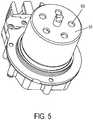
- the figure 5 shows a bottom view of the engine.
- the rotor includes a transverse face (51) having at least one lumen (50) passing through to ensure air circulation towards the coil assembly (41).
- These lumens (50) are configured to provide airflow as the rotor rotates and may be straight bore (as shown) or angled (not shown) to allow forced circulation.
- connection piece (1) which advantageously has locking tabs (30, 31) to possibly prevent the exit of the connection piece (1) during the insertion of the electrical connection plugs.
Landscapes
- Engineering & Computer Science (AREA)
- Power Engineering (AREA)
- Microelectronics & Electronic Packaging (AREA)
- Physics & Mathematics (AREA)
- Electromagnetism (AREA)
- Motor Or Generator Frames (AREA)
Description
- La présente invention concerne le domaine de la connexion électrique de composants électriques sur un circuit imprimé, et notamment des connexions pour le passage de courants élevés, typiquement de 50 à 200 ampères, à des tensions de 12 à 72 volts.
- Un exemple particulier et non limitatif d'application concerne le raccordement des bobinages d'un moteur électrique à un circuit imprimé.
- On connaît dans l'état de la technique la demande de brevet allemand
DE102007032872 décrivant la réalisation d'un moteur à rotor extérieur ayant, à son stator, une pluralité de bobines d'excitation. - On connaît aussi la demande de brevet internationale
WO2009062469 qui décrit un conducteur électrique, en particulier sous forme de conducteur plat d'une grille estampée. L'invention vise particulièrement à économiser du cuivre en réalisant le conducteur sous forme de matériau composite stratifié, avec une couche de cuivre sur les deux côtés de laquelle sont apposées des couches d'aluminium. - Le brevet européen
EP1531522 décrit un contact de raccordement électrique. L'invention propose de former le contact de raccordement avec une zone d'impression à au moins deux couches avec au moins trois (par exemple six) branches ressort par un processus d'estampage et de matriçage, qui forment, ensemble, un ressort en forme d'étoile. La zone d'impression de l'invention améliore la liaison électrique et mécanique avec une plaque conductrice non représentée (multicouche) ou avec un grillage estampé. Le contact de raccordement est réalisé sans brasage. - Le brevet européen
EP0887883 décrit un contact pour un emmanchement dans un trou métallisé d'une carte imprimée, comprenant un ressort de contact ou une fiche de contact, un élément de tige venant se raccorder dessus et une fiche de raccordement formant un prolongement de l'élément de tige central. - Le brevet américain
US7377823 concerne une broche qui est enfoncée dans un trou traversant conducteur pratiqué dans une carte à circuit imprimé. La broche comporte une partie de contact, une partie d'épaulement, une partie à enfoncer et une partie d'extrémité. La partie de contact forme une borne d'un connecteur mâle à monter sur la carte à circuit imprimé par insertion dans un boîtier du connecteur mâle le long de la partie d'épaulement. Le mécanisme d'ajustage par frottement est donc réalisé par frottement dans le trou traversant, ce qui permet de fixer mécaniquement la broche à enfoncer sur la carte à circuit imprimé. - Le document
DE10149574 révèle une grille estampée pour l'électricité centrale dans les véhicules automobiles ayant un contact de connexion sous la forme d'une lame recevant un contact. - Le document
DE102004006575 révèle un distributeur d'électricité ayant au moins une structure de grille perforée dans laquelle des contacts sont enfoncés. - Les solutions de l'art antérieur présentent différentes solutions qui sont adaptées pour le passage de fortes puissances (plusieurs kilowatts typiquement), mais ne permettent pas le raccordement aisé d'un moteur électrique d'une part à un circuit imprimé d'autre part. Par ailleurs, les solutions de l'art antérieur ne permettent pas un mode d'assemblage adapté à un montage rapide d'un tel ensemble de connexion (moteur et circuit imprimé).
- Afin de remédier à ces inconvénients, l'invention concerne selon son acception la plus générale un moteur électrique comportant un circuit imprimé présentant un insert conducteur traversé par des trous de connexion et un ensemble bobiné présentant des liaisons électriques terminées par des fiches de connexion, comportant en outre des pièces de connexion présentant une tige dont la section transversale extérieure est complémentaire de la section desdits trous de connexion, la pièce de connexion présentant à son extrémité proximal un épaulement d'une section supérieure à la section desdits trous de connexion, l'extrémité opposée présentant une fente s'étendant jusqu'audit épaulement et présentant du coté distal une ouverture de largeur supérieure ou égale à la section desdites fiches de connexions et au moins un rétrécissement de largeur inférieure à la section desdites fiches de connexion, pour assurer une expansion du col de ladite pièce de connexion engagée dans le trou de l'insert du circuit imprimé.
- Selon une variante, ladite fente s'étend au-delà dudit épaulement, en direction proximale, ladite pièce de connexion présentant au moins une gorge extérieure pour son insertion par déformation élastique dans un trou de l'insert.
- Selon une autre variante, ladite pièce de connexion présente deux jambes déformables élastiquement, prolongés par un épaulement et définissant une fente présentant au moins un rétrécissement.
- De préférence, les trous de connexion présentent une partie centrale délimitée par deux bords rectilignes parallèles distants d'une largeur correspondant à l'épaisseur de la pièce de connexion au niveau de l'épaulement, ladite partie centrale étant prolongée de part et d'autre par une zone élargie.
- Avantageusement, lesdites zones élargies présentent des bords rectilignes parallèles distants d'une largeur correspondant à la largeur dudit col de la pièce de connexion.
- Selon une variante, chacune desdites jambes présente une protubérance intérieure définissant ledit rétrécissement.
- Selon une autre variante, chacune desdites jambes présente une zone de renfoncement extérieure en-dessous dudit col, chacune des jambes présentant en outre une patte de blocage s'étendant depuis l'extrémité inférieure dudit renfoncement jusqu'au niveau inférieur du col.
- De préférence, ladite pièce de connexion est constituée par une superposition d'une pluralité de tôles conductrices superposées.
- Selon une autre variante avantageuse, ledit ensemble bobiné est disposé à l'intérieur d'un rotor tubulaire, ledit ensemble bobiné étant formé de bobines portées par des dents constituées par un paquet de tôles ferromagnétiques, lesdites dents s'étendant radialement par rapport à un noyau tubulaire ferromagnétique entourant un cœur en un matériau conducteur thermiquement présentant une première section en contact avec le boîtier et une deuxième section de rayon moindre en contact avec ledit noyau tubulaire du moteur, ledit cœur étant en contact avec le boîtier extérieur du moteur pour assurer l'évacuation de la chaleur produit par les bobines.
- Selon une autre variante, les pièces ferromagnétiques sont constituées de matière magnétique frittée ou injectée, ou d'une combinaison de paquets de tôles et de telles matières.
- Avantageusement, ledit matériau conducteur thermiquement présente une forme de « T ».
- De préférence, ledit cœur présente un évidemment traversant pour le passage d'un axe solidaire dudit rotor tubulaire extérieure et entraînant un aimant disposé au voisinage d'une sonde de détection fixée sur ledit circuit imprimé positionné dans le prolongement dudit cœur.
- Selon une variante, l'aimant est disposé dans une cavité de l'axe ou d'une pièce additionnelle, les parois de cette cavité servant de blindage électromagnétique.
- Selon une variante, ladite sonde de détection est positionnée dans l'axe dudit coeur.
- Selon un mode de réalisation particulier, ledit évidemment du cœur présente au moins un roulement pour le guidage dudit axe du rotor tubulaire.
- Selon un autre mode de réalisation, le rotor comprend une face transversale présentant au moins une lumière traversante pour assurer une circulation d'air vers l'ensemble bobiné.
- Avantageusement, lesdites lumières sont configurées pour assurer un forçage de l'air circulant lors de la rotation du rotor.
- Selon une autre variante, l'ensemble rotatif comporte une protubérance ferromagnétique formant un blindage dans le voisinage de la sonde de détection.
- L'invention concerne aussi un ensemble de connexion constitué par un circuit imprimé présentant un insert conducteur traversé par des trous de connexion et une pluralité de liaisons électriques terminées par des fiches de connexion complémentaires, comportant en outre des pièces de connexion (1) présentant une tige dont la section transversale extérieure est complémentaire de la section desdits trous de connexion, la pièce de connexion présentant à son extrémité proximal un épaulement d'une section supérieure à la section desdits trous de connexion, l'extrémité opposée présentant une fente s'étendant jusqu'audit épaulement et présentant du côté distal une ouverture de largeur supérieure ou égale à la section desdites fiches de connexions et au moins un rétrécissement de largeur inférieure à la section desdites fiches de connexion, pour assurer une expansion du col de ladite pièce de connexion engagée dans le trou de l'insert du circuit imprimé.
- La présente invention sera mieux comprise à la lecture de la description qui suit, se référant aux dessins annexés où :
- la
figure 1 représente une vue en coupe d'un ensemble de connexion selon l'invention ; - la
figure 2 représente une vue en coupe transversale d'un ensemble de connexion selon l'invention, dans le plan de l'insert ; - la
figure 3 représente une vue en coupe d'une variante de réalisation d'une pièce de connexion ; - la
figure 4 représente une vue en coupe d'un moteur à rotor extérieur selon l'invention ; - la
figure 5 représente une vue de trois-quart inférieur du moteur selon l'invention. - La
figure 1 représente un exemple de réalisation d'une pièce de connexion (1) présentant deux jambes (2, 3) parallèles reliées par une tête (4). - Le système de connexion comprend plusieurs pièces de connexion (1) et un circuit imprimé (10) présentant des inserts métalliques (7) complémentaires.
- Les deux jambes (2, 3) définissent entre elles une fente (5) s'étendant jusqu'au niveau d'un col (6). La pièce de connexion (1) est constituée par un empilement de tôles découpées.
- La pièce (1) vient se loger dans un insert (7) métallique placé entre deux couches isolantes (8, 9) pour former un circuit imprimé comportant par ailleurs de façon connue des pistes conductrices (28) à la surface d'une des couches isolantes au moins.
- L'insert (7) présente une découpe oblongue (11) dont la
figure 2 représente une vue agrandie. - La découpe (11) présente une zone centrale délimitée par deux bords rectilignes (12, 13) parallèles venant en contact avec les surfaces latérales de la tête (4) de la pièce de connexion (1). Cette zone centrale est prolongée de part et d'autre par des excroissances (15, 16) de plus grande largeur, présentant chacune un bord (17, 18) de forme complémentaire à l'arête des jambes respectivement (2, 3), au niveau du col (6) de la pièce de connexion (1).
- Les zones de contact électriques entre la pièce de connexion (1) et l'insert (7) correspondent aux bords (12, 13 et 17, 18). L'insert (7) présente une épaisseur d'environ 1 millimètre, et de préférence entre 0,5 et 2 millimètres, ce qui garantit une surface de contact suffisante pour passer des puissances électriques élevées, de 10KW par exemple pour un courant de 200 ampères sous une tension de 48 volts.
- Les zones élargies (15, 16) permettent un basculement de la pièce de connexion (1), ce qui assure une tolérance géométrique lors de l'assemblage du système de connexion.
- L'insert (7) présente dans l'exemple décrit une nervure (22) assurant une flexibilité facilitant l'insertion du col (6) de la pièce de connexion.
- La pièce de connexion (1) présente un épaulement (20) limitant le déplacement de la pièce de connexion (1) lors de son insertion dans le circuit imprimé.
- Les jambes (2, 3) présentent chacune une protubérance (32, 33) dirigée vers l'intérieur de la fente (5) afin de réduire localement la largeur de la fente (5). L'extrémité distale de la fente (5) est évasée grâce à des chanfreins et/ou des rayons (24, 25) prévus à la surface intérieure de l'extrémité des jambes respectivement (2, 3).
- La partie complémentaire à raccorder comprend une fiche de connexion (26) formée par une lame plane, par exemple en laiton ou en cuivre, dont l'extrémité (27) présente une forme de pointe. Lors de son insertion dans la fente (5) d'une pièce de connexion (1), elle provoque l'écartement des jambes (2, 3) lorsque l'extrémité (27) rencontre les protubérances (32, 33). Cet écartement se traduit par une légère expansion transversale de la pièce (1) au niveau du col (6), ce qui renforce le contact entre la bordure périphérique de la pièce (1) au niveau de son col (6), et les bords (17, 18) de la découpe de l'insert. L'élasticité des jambes (2, 3) permet de contrôler la force d'appui du col (6) sur les bords de la découpe (11) de l'insert (7).
- Dans l'exemple décrit en
figure 1 , la pièce (1) présente un deuxième épaulement (29) définissant, avec le premier épaulement (20) le col. - Le deuxième épaulement (29) est de section légèrement supérieure à la section de la découpe (11) de l'insert (7). Il peut néanmoins passer en force en raison de l'élasticité de la nervure (22) prévue sur les bords de la découpe de l'insert (7) et de la flexibilité de la pièce de connexion (1).
- Le fonctionnement de ce premier exemple de réalisation est le suivant :
On prépare le circuit imprimé avec ses inserts (7) découpés. Les inserts (7) sont reliés électriquement à des pistes conductrices (28) du circuit imprimé par des connexions électriques (14). - On introduit ensuite les pièces de connexions (1) dans les découpes des inserts (7) en les pressant contre la surface supérieure du circuit imprimé ou de l'insert. La flexibilité des inserts permet le passage en force du deuxième épaulement (29) jusqu'à ce que le premier épaulement (20) vienne en contact avec la surface supérieure de l'insert (7).
- On presse ensuite le circuit imprimé équipé des pièces de connexion contre l'équipement complémentaire, présentant des fiches de connexion (26) dirigées en direction du circuit imprimé. Les éventuels désalignements sont possibles en raison de la mobilité en basculement des pièces de connexion (1), ce qui autorise une tolérance d'alignement.
- En pressant l'équipement muni des fiches (26) contre le circuit imprimé, les fiches (26) s'insèrent dans les fentes (5) des pièces de connexion en vis-à-vis, ce qui provoque l'écartement des jambes (2, 3) et l'expansion de la pièce de connexion (1) au niveau du col (6), et donc le renforcement du contact mécanique et électrique entre le col (6) de la pièce de connexion (1) et l'insert (7).
- La
figure 4 représente un exemple de moteur à rotor (40) extérieur mettant en œuvre un tel système de connexion. - Le stator est constitué par un stator bobiné (41) monté sur un cœur (42). Les bobines sont alimentées par des conducteurs terminés par des fiches de connexion (26) venant s'insérer dans des pièces de connexion (1) montés sur un circuit imprimé (10). L'avantage de ce système de connexion est qu'il permet de réaliser industriellement la partie basse du moteur, comprenant le rotor extérieur (40) et le stator bobiné d'une part, et la partie haute comprenant les parties électronique d'autre part, puis d'assembler par un simple assemblage mécanique consistant à presser les deux parties l'une contre l'autre, afin d'assurer à la fois l'assemblage mécanique et électrique.
- Le stator présente un cœur (42) assurant à la fois la tenue mécanique du stator bobiné (41), et aussi l'évacuation de la puissance dissipée dans ledit stator bobiné. Dans le cas d'un moteur à rotor extérieur, la chaleur produite par l'ensemble bobiné (41) est difficile à évacuer car confinée à l'intérieur du moteur. L'invention concerne un cœur (42) présentant une première section (42a) entourée par le stator bobiné (41), prolongée par une deuxième section (42b) de diamètre supérieur, de forme tronconique. Le cœur (42) présente ainsi une section globalement en forme de « T ». La deuxième section (42b) est en contact avec le boîtier métallique (44). Cette architecture permet d'améliorer la transmission de chaleur dégagée par les bobines du moteur et les pertes fer pour l'évacuer vers le boîtier (44) métallique. Le cœur (42) présente un évidemment (45) axial qui est traversé par un axe (46) solidaire du rotor (40) extérieur. Il entraîne un aimant (47) disposé au voisinage d'une sonde de détection (48) fixée sur ledit circuit imprimé positionné dans le prolongement du cœur (42). La sonde de détection (48) est positionnée dans l'axe du cœur (42). L'évidemment présente un roulement (49) pour le guidage de l'axe du rotor tubulaire.
- L'aimant (47) est disposé dans une cavité (52), les parois de ladite cavité assurant un blindage autour de la sonde de détection (48).
- La
figure 5 représente une vue de dessous du moteur. Le rotor comprend une face transversale (51) présentant au moins une lumière (50) traversant pour assurer une circulation d'air vers l'ensemble bobiné (41). Ces lumières (50) sont configurées pour assurer une circulation de l'air lors de la rotation du rotor et peuvent être à perçage droit (comme illustré) ou incliné (non montré) pour permettre une circulation forcée. - La
figure 3 présente une réalisation alternative de la pièce de connexion (1) qui présente avantageusement des pattes de blocage (30, 31) pour éventuellement éviter la sortie de la pièce de connexion (1) lors de l'insertion des fiches de connexion électriques.
Claims (17)
- Ensemble de connexion constitué par un circuit imprimé présentant un insert (7) conducteur traversé par des trous de connexion et une pluralité de liaisons électriques terminées par des fiches de connexion (26) complémentaires comportant en outre des pièces de connexion présentant une tige dont la section transversale extérieure est complémentaire de la section desdits trous de connexion, chacune des pièces de connexion (1) présentant à son extrémité proximal un épaulement (20) d'une section supérieure à la section desdits trous de connexion, l'extrémité distale présentant une fente (5) s'étendant jusque à un col, qui est inséré dans ledit trou de connexion, et jusqu'audit épaulement et présentant du côté distal une ouverture de largeur supérieure ou égale à la section desdites fiches de connexion (26) et au moins un rétrécissement de largeur inférieure à la section desdites fiches de connexion (26), pour assurer une expansion du col de ladite pièce de connexion (1) engagée dans le trou de l'insert du circuit imprimé.
- Moteur électrique comportant un ensemble de connexion selon la revendication 1 présentant un insert (7) conducteur traversé par des trous de connexion et un ensemble bobiné (41) présentant des liaisons électriques terminées par des fiches de connexion (26) caractérisé en ce qu'il comporte en outre des pièces de connexion (1) présentant une tige dont la section transversale extérieure est complémentaire de la section desdits trous de connexion, la pièce de connexion (1) présentant à son extrémité proximale un épaulement (20) d'une section supérieure à la section desdits trous de connexion, l'extrémité distal présentant une fente (5) s'étendant jusqu'audit épaulement et présentant du côté distal une ouverture de largeur supérieure ou égale à la section desdites fiches de connexion (26) et au moins un rétrécissement de largeur inférieure à la section desdites fiches de connexion (26), pour assurer une expansion du col de ladite pièce de connexion (1) engagée dans le trou de l'insert du circuit imprimé.
- Moteur électrique selon la revendication 2 caractérisé en ce que ladite fente (5) s'étend au-delà dudit épaulement, en direction proximale, ladite pièce de connexion (1) présentant au moins une gorge extérieure pour son insertion par déformation élastique dans un trou de l'insert.
- Moteur électrique selon la revendication 2 caractérisé en ce que ladite pièce de connexion (1) présente deux jambes (2, 3) déformables élastiquement, prolongées par un épaulement (20) et définissant une fente (5) présentant au moins un rétrécissement.
- Moteur électrique selon l'une au moins des revendications précédentes caractérisé en ce que les trous de connexion présentent une partie centrale délimitée par deux bords rectilignes (12, 13) parallèles distant d'une largeur correspondant à l'épaisseur de la pièce de connexion (1) au niveau de l'épaulement, ladite partie centrale étant prolongée de part et d'autre par une zone élargie.
- Moteur électrique selon la revendication précédente caractérisé en ce que lesdites zones élargies présentent des bords (17, 18) distant d'une largeur correspondant à la largeur dudit col de la pièce de connexion (1).
- Moteur électrique selon la revendication 4 caractérisé en ce que chacune desdites jambes (2, 3) présente une protubérance intérieure (22, 23, 32, 33) définissant ledit rétrécissement.
- Moteur électrique selon l'une au moins des revendications précédentes caractérisé en ce que chacune desdites jambes présente une zone de renfoncement extérieure en-dessous dudit col, chacune des jambes (2, 3) présentant en outre une patte de blocage (30, 31) s'étendant depuis l'extrémité inférieure dudit renfoncement jusqu'au niveau inférieur du col.
- Moteur électrique selon l'une au moins des revendications précédentes caractérisé en ce que ladite pièce de connexion (1) est constituée par une superposition d'une pluralité de tôles conductrices superposées.
- Moteur électrique selon l'une au moins des revendications précédentes caractérisé en ce que ledit ensemble bobiné est disposé à l'intérieur d'un rotor (40) tubulaire, ledit ensemble bobiné étant formé de bobines portées par des dents constituées par un paquet de tôles ferromagnétiques, lesdites dents s'étendant radialement par rapport à un noyau (43) tubulaire ferromagnétique entourant un cœur en un matériau conducteur thermiquement présentant une première section (42b) en contact avec le boîtier (44) et une deuxième section (42a) de rayon moindre en contact avec ledit noyau tubulaire du moteur, ledit cœur étant en contact avec le boîtier extérieur (44) du moteur pour assurer l'évacuation de la chaleur produite par les bobines.
- Moteur électrique selon la revendication précédente caractérisé en ce que ledit matériau conducteur thermiquement présente une forme de « T ».
- Moteur électrique selon la revendication précédente caractérisé en ce que ledit cœur présente un évidemment (45) traversant pour le passage d'un axe (46) solidaire dudit rotor tubulaire extérieure et entraînant un aimant (47) disposé au voisinage d'une sonde de détection (48) fixée sur ledit circuit imprimé positionné dans le prolongement dudit cœur.
- Moteur électrique selon la revendication précédente caractérisé en ce que ladite sonde de détection (48) est positionnée dans l'axe dudit coeur.
- Moteur électrique selon la revendication 12 caractérisé en ce que ledit évidemment du cœur présente au moins un roulement (49) pour le guidage dudit axe du rotor tubulaire.
- Moteur électrique selon la revendication 12 caractérisé en ce que le rotor comprend une face transversale (51) présentant au moins une lumière (50) traversante pour assurer une circulation d'air vers l'ensemble bobiné.
- Moteur électrique selon la revendication précédente caractérisé en ce que lesdites lumières (50) sont configurées pour assurer un forçage de l'air circulant lors de la rotation du rotor.
- Moteur électrique selon la revendication 12 caractérisé en ce que l'ensemble rotatif comporte une protubérance ferromagnétique (53) formant un blindage dans le voisinage de la sonde de détection (48).
Applications Claiming Priority (2)
| Application Number | Priority Date | Filing Date | Title |
|---|---|---|---|
| FR1562199A FR3045236B1 (fr) | 2015-12-11 | 2015-12-11 | Moteur electrique |
| PCT/EP2016/080016 WO2017097807A1 (fr) | 2015-12-11 | 2016-12-07 | Moteur électrique |
Publications (2)
| Publication Number | Publication Date |
|---|---|
| EP3387737A1 EP3387737A1 (fr) | 2018-10-17 |
| EP3387737B1 true EP3387737B1 (fr) | 2021-04-21 |
Family
ID=55759715
Family Applications (1)
| Application Number | Title | Priority Date | Filing Date |
|---|---|---|---|
| EP16806144.8A Active EP3387737B1 (fr) | 2015-12-11 | 2016-12-07 | Moteur électrique |
Country Status (7)
| Country | Link |
|---|---|
| US (1) | US10784601B2 (fr) |
| EP (1) | EP3387737B1 (fr) |
| JP (1) | JP7050675B2 (fr) |
| KR (1) | KR102890809B1 (fr) |
| CN (1) | CN108604836B (fr) |
| FR (1) | FR3045236B1 (fr) |
| WO (1) | WO2017097807A1 (fr) |
Cited By (1)
| Publication number | Priority date | Publication date | Assignee | Title |
|---|---|---|---|---|
| US11837935B2 (en) | 2021-02-02 | 2023-12-05 | Black & Decker, Inc. | Canned brushless motor |
Families Citing this family (2)
| Publication number | Priority date | Publication date | Assignee | Title |
|---|---|---|---|---|
| US11658530B2 (en) | 2021-07-15 | 2023-05-23 | Stoneridge, Inc. | Modular brushless DC (BLDC) motor construction |
| FR3166497A1 (fr) | 2024-09-16 | 2026-03-20 | Sonceboz Mechatronics Boncourt Sa | Dispositif d’entrainement à assemblage facilité |
Citations (2)
| Publication number | Priority date | Publication date | Assignee | Title |
|---|---|---|---|---|
| DE102004006575A1 (de) * | 2004-02-11 | 2005-09-01 | Leopold Kostal Gmbh & Co Kg | Leistungsverteiler für ein Kraftfahrzeug |
| DE102010039747A1 (de) * | 2010-08-25 | 2012-03-01 | Robert Bosch Gmbh | Kontaktelement zur Kontaktierung eines Verbrauchers mit einem Steuergerät, Anordnung aus einem Verbraucher und einem Steuergerät, sowie Verfahren zur Montage einer solchen Anordnung |
Family Cites Families (24)
| Publication number | Priority date | Publication date | Assignee | Title |
|---|---|---|---|---|
| JPS582976U (ja) * | 1981-06-30 | 1983-01-10 | パイオニア株式会社 | プリント基板用接続端子 |
| DE19726759A1 (de) | 1997-06-24 | 1999-01-07 | Elco Europ Gmbh | Einpreßkontakt |
| JP4091247B2 (ja) | 2000-12-07 | 2008-05-28 | カルソニックカンセイ株式会社 | ブラシレスモータ |
| JP4018357B2 (ja) * | 2001-01-16 | 2007-12-05 | カルソニックカンセイ株式会社 | ブラシレスモータ |
| DE10149574C2 (de) * | 2001-10-08 | 2003-10-09 | Wolf Neumann-Henneberg | Stanzgitter mit einem Messeraufnahmekontakt |
| JP2003116254A (ja) | 2002-09-30 | 2003-04-18 | Zexel Valeo Climate Control Corp | ブラシレスモータ |
| DE10352761B4 (de) | 2003-11-12 | 2006-06-08 | Wolf Neumann-Henneberg | Anschlusskontakt zur elektrischen Kontaktierung einer Leiterplatte oder eines Stanzgitters |
| JP4506456B2 (ja) * | 2004-12-24 | 2010-07-21 | 住友電装株式会社 | 回路基板への基板用端子の取付構造 |
| US7337823B2 (en) | 2005-02-26 | 2008-03-04 | Irvin Automotive Products, Inc. | Extending end cap for a security shade |
| US7377823B2 (en) * | 2005-05-23 | 2008-05-27 | J.S.T. Corporation | Press-fit pin |
| FR2890780B1 (fr) * | 2005-09-15 | 2007-10-12 | Valeo Equip Electr Moteur | Contacteur de demarreur de moteur thermique comportant des moyens perfectionnes de raccordement electrique de son bobinage |
| JP2007122952A (ja) * | 2005-10-26 | 2007-05-17 | Auto Network Gijutsu Kenkyusho:Kk | プレスフィット端子と基板の接続構造 |
| US7946861B2 (en) * | 2007-02-02 | 2011-05-24 | Fci | Connection device |
| JP2008262897A (ja) * | 2007-03-16 | 2008-10-30 | Advics:Kk | 端子および端子と基板との接続構造 |
| DE102007032872A1 (de) | 2007-07-12 | 2009-01-15 | Ipgate Ag | Stator für Elektromotor |
| DE102007054418A1 (de) | 2007-11-13 | 2009-05-14 | Wolf Neumann-Henneberg | Elektrischer Leiter und Stanzgitter mit Stegleitern aus einem solchen elektrischen Leiter |
| US7780483B1 (en) * | 2008-12-09 | 2010-08-24 | Anthony Ravlich | Electrical press-fit contact |
| CN101764305B (zh) * | 2008-12-26 | 2012-04-25 | 凡甲电子(苏州)有限公司 | 电力连接器 |
| JP2013009573A (ja) * | 2011-06-27 | 2013-01-10 | Nidec Sankyo Corp | モータ |
| FR2978883B1 (fr) | 2011-08-01 | 2013-07-26 | Moving Magnet Tech | Ensemble compact de positionnement comprenant un actionneur et un capteur integre dans la culasse de l'actionneur |
| FR2986066B1 (fr) | 2012-01-23 | 2014-12-26 | Moving Magnet Tech | Module indicateur de position a axe illumine |
| JP2013201804A (ja) | 2012-03-23 | 2013-10-03 | Hitachi Automotive Systems Ltd | 機電一体型駆動装置 |
| GB2509516B (en) * | 2013-01-04 | 2015-07-15 | Controlled Power Technologies Ltd | Position sensing system |
| FR3019951B1 (fr) * | 2014-04-11 | 2016-04-29 | Valeo Systemes Thermiques | Moteur electrique, dispositif de pulsion d'air et systeme de ventilation de chauffage et/ou de climatisation equipes d'un tel moteur |
-
2015
- 2015-12-11 FR FR1562199A patent/FR3045236B1/fr not_active Expired - Fee Related
-
2016
- 2016-12-07 WO PCT/EP2016/080016 patent/WO2017097807A1/fr not_active Ceased
- 2016-12-07 EP EP16806144.8A patent/EP3387737B1/fr active Active
- 2016-12-07 KR KR1020187018937A patent/KR102890809B1/ko active Active
- 2016-12-07 CN CN201680081014.8A patent/CN108604836B/zh active Active
- 2016-12-07 JP JP2018529605A patent/JP7050675B2/ja active Active
- 2016-12-07 US US16/060,533 patent/US10784601B2/en active Active
Patent Citations (2)
| Publication number | Priority date | Publication date | Assignee | Title |
|---|---|---|---|---|
| DE102004006575A1 (de) * | 2004-02-11 | 2005-09-01 | Leopold Kostal Gmbh & Co Kg | Leistungsverteiler für ein Kraftfahrzeug |
| DE102010039747A1 (de) * | 2010-08-25 | 2012-03-01 | Robert Bosch Gmbh | Kontaktelement zur Kontaktierung eines Verbrauchers mit einem Steuergerät, Anordnung aus einem Verbraucher und einem Steuergerät, sowie Verfahren zur Montage einer solchen Anordnung |
Cited By (6)
| Publication number | Priority date | Publication date | Assignee | Title |
|---|---|---|---|---|
| US11837935B2 (en) | 2021-02-02 | 2023-12-05 | Black & Decker, Inc. | Canned brushless motor |
| US11855521B2 (en) | 2021-02-02 | 2023-12-26 | Black & Decker, Inc. | Brushless DC motor for a body-grip power tool |
| US11870316B2 (en) | 2021-02-02 | 2024-01-09 | Black & Decker, Inc. | Brushless motor including a nested bearing bridge |
| US11876424B2 (en) | 2021-02-02 | 2024-01-16 | Black & Decker Inc. | Compact brushless motor including in-line terminals |
| US11955863B2 (en) | 2021-02-02 | 2024-04-09 | Black & Decker Inc. | Circuit board assembly for compact brushless motor |
| US12261497B2 (en) | 2021-02-02 | 2025-03-25 | Black & Decker Inc. | High-power motor for a body-grip power tool |
Also Published As
| Publication number | Publication date |
|---|---|
| CN108604836B (zh) | 2021-05-28 |
| KR20180093008A (ko) | 2018-08-20 |
| EP3387737A1 (fr) | 2018-10-17 |
| US20180366848A1 (en) | 2018-12-20 |
| FR3045236B1 (fr) | 2018-01-19 |
| KR102890809B1 (ko) | 2025-11-26 |
| WO2017097807A1 (fr) | 2017-06-15 |
| JP7050675B2 (ja) | 2022-04-08 |
| FR3045236A1 (fr) | 2017-06-16 |
| US10784601B2 (en) | 2020-09-22 |
| CN108604836A (zh) | 2018-09-28 |
| JP2019504594A (ja) | 2019-02-14 |
Similar Documents
| Publication | Publication Date | Title |
|---|---|---|
| US8002575B2 (en) | Cable assembly with strain relief member | |
| EP2195886B1 (fr) | Clip de contact | |
| EP3682531B1 (fr) | Système de connexion pour machine électrique | |
| WO1989001248A1 (fr) | Connecteur a semelle retractable prevu pour la protection des sorties de contact | |
| FR2997565A1 (fr) | Dispositif de connexion pour la transmission de courant haute tension dans le domaine des vehicules automobiles | |
| EP3560072A1 (fr) | Motoreducteur compact | |
| WO2017097807A1 (fr) | Moteur électrique | |
| EP2146400B1 (fr) | Ensemble de connexion et procédé de montage d'un tel ensemble de connexion | |
| FR2990083A1 (fr) | Machine electrique comportant un stator forme de segments et son procede de realisation | |
| JP5138963B2 (ja) | モータ | |
| FR2804256A1 (fr) | Stator pour une machine dynamo-electrique | |
| WO2016199077A1 (fr) | Dispositif de connexion électrique entre un moteur électrique et une unité d'alimentation dudit moteur, notamment pour compresseur de véhicule automobile | |
| EP2745661B1 (fr) | Dispositif de connexion electrique, ensemble comprenant un tel dispositif et une carte electronique et procede de connexion electrique d'une carte electronique | |
| FR3062000B1 (fr) | Isolant rigide pour bobinage de rotor de moteur electrique | |
| JP2008252970A (ja) | モータ | |
| EP2253049B1 (fr) | Machine comprenant un dispositif pour prevenir l'etablissement d'un arc electrique entre deux elements conducteurs | |
| CN112368915A (zh) | 马达 | |
| EP1006549B1 (fr) | Appareil interrupteur électromagnétique | |
| WO2013053476A2 (fr) | Systeme de maintien mecanique, ensemble comprenant un tel systeme et une carte electronique et procede d'assemblage sur une surface d'un tel systeme et d'une telle carte | |
| EP1925011B1 (fr) | Contacteur de demarreur de moteur thermique comportant des moyens perfectionnes de raccordement electrique de son bobinage | |
| EP2512008B1 (fr) | Ensemble comprenant un stator et une boite a borne pour l'alimentation electrique du stator | |
| CA1298372C (fr) | Connecteur a semelle retractable prevu pour la protection des sorties de contact | |
| EP1371113B1 (fr) | Connecteur de puissance pour circuit imprime | |
| JP2008252971A (ja) | モータ | |
| FR2730849A1 (fr) | Transformateur, notamment pour convertisseur d'energie, et convertisseur d'energie a resonnance dote d'un tel transformateur |
Legal Events
| Date | Code | Title | Description |
|---|---|---|---|
| STAA | Information on the status of an ep patent application or granted ep patent |
Free format text: STATUS: UNKNOWN |
|
| STAA | Information on the status of an ep patent application or granted ep patent |
Free format text: STATUS: THE INTERNATIONAL PUBLICATION HAS BEEN MADE |
|
| PUAI | Public reference made under article 153(3) epc to a published international application that has entered the european phase |
Free format text: ORIGINAL CODE: 0009012 |
|
| STAA | Information on the status of an ep patent application or granted ep patent |
Free format text: STATUS: REQUEST FOR EXAMINATION WAS MADE |
|
| 17P | Request for examination filed |
Effective date: 20180611 |
|
| AK | Designated contracting states |
Kind code of ref document: A1 Designated state(s): AL AT BE BG CH CY CZ DE DK EE ES FI FR GB GR HR HU IE IS IT LI LT LU LV MC MK MT NL NO PL PT RO RS SE SI SK SM TR |
|
| AX | Request for extension of the european patent |
Extension state: BA ME |
|
| DAV | Request for validation of the european patent (deleted) | ||
| DAX | Request for extension of the european patent (deleted) | ||
| STAA | Information on the status of an ep patent application or granted ep patent |
Free format text: STATUS: EXAMINATION IS IN PROGRESS |
|
| 17Q | First examination report despatched |
Effective date: 20200103 |
|
| GRAP | Despatch of communication of intention to grant a patent |
Free format text: ORIGINAL CODE: EPIDOSNIGR1 |
|
| STAA | Information on the status of an ep patent application or granted ep patent |
Free format text: STATUS: GRANT OF PATENT IS INTENDED |
|
| INTG | Intention to grant announced |
Effective date: 20200812 |
|
| GRAJ | Information related to disapproval of communication of intention to grant by the applicant or resumption of examination proceedings by the epo deleted |
Free format text: ORIGINAL CODE: EPIDOSDIGR1 |
|
| STAA | Information on the status of an ep patent application or granted ep patent |
Free format text: STATUS: EXAMINATION IS IN PROGRESS |
|
| GRAP | Despatch of communication of intention to grant a patent |
Free format text: ORIGINAL CODE: EPIDOSNIGR1 |
|
| STAA | Information on the status of an ep patent application or granted ep patent |
Free format text: STATUS: GRANT OF PATENT IS INTENDED |
|
| INTC | Intention to grant announced (deleted) | ||
| INTG | Intention to grant announced |
Effective date: 20201223 |
|
| GRAS | Grant fee paid |
Free format text: ORIGINAL CODE: EPIDOSNIGR3 |
|
| GRAA | (expected) grant |
Free format text: ORIGINAL CODE: 0009210 |
|
| STAA | Information on the status of an ep patent application or granted ep patent |
Free format text: STATUS: THE PATENT HAS BEEN GRANTED |
|
| AK | Designated contracting states |
Kind code of ref document: B1 Designated state(s): AL AT BE BG CH CY CZ DE DK EE ES FI FR GB GR HR HU IE IS IT LI LT LU LV MC MK MT NL NO PL PT RO RS SE SI SK SM TR |
|
| REG | Reference to a national code |
Ref country code: GB Ref legal event code: FG4D Free format text: NOT ENGLISH |
|
| REG | Reference to a national code |
Ref country code: CH Ref legal event code: EP |
|
| REG | Reference to a national code |
Ref country code: DE Ref legal event code: R096 Ref document number: 602016056574 Country of ref document: DE Ref country code: IE Ref legal event code: FG4D Free format text: LANGUAGE OF EP DOCUMENT: FRENCH |
|
| REG | Reference to a national code |
Ref country code: AT Ref legal event code: REF Ref document number: 1385669 Country of ref document: AT Kind code of ref document: T Effective date: 20210515 |
|
| REG | Reference to a national code |
Ref country code: LT Ref legal event code: MG9D |
|
| REG | Reference to a national code |
Ref country code: AT Ref legal event code: MK05 Ref document number: 1385669 Country of ref document: AT Kind code of ref document: T Effective date: 20210421 |
|
| REG | Reference to a national code |
Ref country code: NL Ref legal event code: MP Effective date: 20210421 |
|
| PG25 | Lapsed in a contracting state [announced via postgrant information from national office to epo] |
Ref country code: FI Free format text: LAPSE BECAUSE OF FAILURE TO SUBMIT A TRANSLATION OF THE DESCRIPTION OR TO PAY THE FEE WITHIN THE PRESCRIBED TIME-LIMIT Effective date: 20210421 Ref country code: NL Free format text: LAPSE BECAUSE OF FAILURE TO SUBMIT A TRANSLATION OF THE DESCRIPTION OR TO PAY THE FEE WITHIN THE PRESCRIBED TIME-LIMIT Effective date: 20210421 Ref country code: LT Free format text: LAPSE BECAUSE OF FAILURE TO SUBMIT A TRANSLATION OF THE DESCRIPTION OR TO PAY THE FEE WITHIN THE PRESCRIBED TIME-LIMIT Effective date: 20210421 Ref country code: BG Free format text: LAPSE BECAUSE OF FAILURE TO SUBMIT A TRANSLATION OF THE DESCRIPTION OR TO PAY THE FEE WITHIN THE PRESCRIBED TIME-LIMIT Effective date: 20210721 Ref country code: AT Free format text: LAPSE BECAUSE OF FAILURE TO SUBMIT A TRANSLATION OF THE DESCRIPTION OR TO PAY THE FEE WITHIN THE PRESCRIBED TIME-LIMIT Effective date: 20210421 Ref country code: HR Free format text: LAPSE BECAUSE OF FAILURE TO SUBMIT A TRANSLATION OF THE DESCRIPTION OR TO PAY THE FEE WITHIN THE PRESCRIBED TIME-LIMIT Effective date: 20210421 |
|
| PG25 | Lapsed in a contracting state [announced via postgrant information from national office to epo] |
Ref country code: SE Free format text: LAPSE BECAUSE OF FAILURE TO SUBMIT A TRANSLATION OF THE DESCRIPTION OR TO PAY THE FEE WITHIN THE PRESCRIBED TIME-LIMIT Effective date: 20210421 Ref country code: RS Free format text: LAPSE BECAUSE OF FAILURE TO SUBMIT A TRANSLATION OF THE DESCRIPTION OR TO PAY THE FEE WITHIN THE PRESCRIBED TIME-LIMIT Effective date: 20210421 Ref country code: PL Free format text: LAPSE BECAUSE OF FAILURE TO SUBMIT A TRANSLATION OF THE DESCRIPTION OR TO PAY THE FEE WITHIN THE PRESCRIBED TIME-LIMIT Effective date: 20210421 Ref country code: PT Free format text: LAPSE BECAUSE OF FAILURE TO SUBMIT A TRANSLATION OF THE DESCRIPTION OR TO PAY THE FEE WITHIN THE PRESCRIBED TIME-LIMIT Effective date: 20210823 Ref country code: NO Free format text: LAPSE BECAUSE OF FAILURE TO SUBMIT A TRANSLATION OF THE DESCRIPTION OR TO PAY THE FEE WITHIN THE PRESCRIBED TIME-LIMIT Effective date: 20210721 Ref country code: GR Free format text: LAPSE BECAUSE OF FAILURE TO SUBMIT A TRANSLATION OF THE DESCRIPTION OR TO PAY THE FEE WITHIN THE PRESCRIBED TIME-LIMIT Effective date: 20210722 Ref country code: LV Free format text: LAPSE BECAUSE OF FAILURE TO SUBMIT A TRANSLATION OF THE DESCRIPTION OR TO PAY THE FEE WITHIN THE PRESCRIBED TIME-LIMIT Effective date: 20210421 Ref country code: IS Free format text: LAPSE BECAUSE OF FAILURE TO SUBMIT A TRANSLATION OF THE DESCRIPTION OR TO PAY THE FEE WITHIN THE PRESCRIBED TIME-LIMIT Effective date: 20210821 |
|
| REG | Reference to a national code |
Ref country code: DE Ref legal event code: R097 Ref document number: 602016056574 Country of ref document: DE |
|
| PG25 | Lapsed in a contracting state [announced via postgrant information from national office to epo] |
Ref country code: CZ Free format text: LAPSE BECAUSE OF FAILURE TO SUBMIT A TRANSLATION OF THE DESCRIPTION OR TO PAY THE FEE WITHIN THE PRESCRIBED TIME-LIMIT Effective date: 20210421 Ref country code: EE Free format text: LAPSE BECAUSE OF FAILURE TO SUBMIT A TRANSLATION OF THE DESCRIPTION OR TO PAY THE FEE WITHIN THE PRESCRIBED TIME-LIMIT Effective date: 20210421 Ref country code: DK Free format text: LAPSE BECAUSE OF FAILURE TO SUBMIT A TRANSLATION OF THE DESCRIPTION OR TO PAY THE FEE WITHIN THE PRESCRIBED TIME-LIMIT Effective date: 20210421 Ref country code: RO Free format text: LAPSE BECAUSE OF FAILURE TO SUBMIT A TRANSLATION OF THE DESCRIPTION OR TO PAY THE FEE WITHIN THE PRESCRIBED TIME-LIMIT Effective date: 20210421 Ref country code: ES Free format text: LAPSE BECAUSE OF FAILURE TO SUBMIT A TRANSLATION OF THE DESCRIPTION OR TO PAY THE FEE WITHIN THE PRESCRIBED TIME-LIMIT Effective date: 20210421 Ref country code: SK Free format text: LAPSE BECAUSE OF FAILURE TO SUBMIT A TRANSLATION OF THE DESCRIPTION OR TO PAY THE FEE WITHIN THE PRESCRIBED TIME-LIMIT Effective date: 20210421 Ref country code: SM Free format text: LAPSE BECAUSE OF FAILURE TO SUBMIT A TRANSLATION OF THE DESCRIPTION OR TO PAY THE FEE WITHIN THE PRESCRIBED TIME-LIMIT Effective date: 20210421 |
|
| PLBE | No opposition filed within time limit |
Free format text: ORIGINAL CODE: 0009261 |
|
| STAA | Information on the status of an ep patent application or granted ep patent |
Free format text: STATUS: NO OPPOSITION FILED WITHIN TIME LIMIT |
|
| 26N | No opposition filed |
Effective date: 20220124 |
|
| PG25 | Lapsed in a contracting state [announced via postgrant information from national office to epo] |
Ref country code: IS Free format text: LAPSE BECAUSE OF FAILURE TO SUBMIT A TRANSLATION OF THE DESCRIPTION OR TO PAY THE FEE WITHIN THE PRESCRIBED TIME-LIMIT Effective date: 20210821 Ref country code: AL Free format text: LAPSE BECAUSE OF FAILURE TO SUBMIT A TRANSLATION OF THE DESCRIPTION OR TO PAY THE FEE WITHIN THE PRESCRIBED TIME-LIMIT Effective date: 20210421 |
|
| PG25 | Lapsed in a contracting state [announced via postgrant information from national office to epo] |
Ref country code: MC Free format text: LAPSE BECAUSE OF FAILURE TO SUBMIT A TRANSLATION OF THE DESCRIPTION OR TO PAY THE FEE WITHIN THE PRESCRIBED TIME-LIMIT Effective date: 20210421 Ref country code: IT Free format text: LAPSE BECAUSE OF FAILURE TO SUBMIT A TRANSLATION OF THE DESCRIPTION OR TO PAY THE FEE WITHIN THE PRESCRIBED TIME-LIMIT Effective date: 20210421 |
|
| REG | Reference to a national code |
Ref country code: CH Ref legal event code: PL |
|
| GBPC | Gb: european patent ceased through non-payment of renewal fee |
Effective date: 20211207 |
|
| REG | Reference to a national code |
Ref country code: BE Ref legal event code: MM Effective date: 20211231 |
|
| PG25 | Lapsed in a contracting state [announced via postgrant information from national office to epo] |
Ref country code: LU Free format text: LAPSE BECAUSE OF NON-PAYMENT OF DUE FEES Effective date: 20211207 Ref country code: IE Free format text: LAPSE BECAUSE OF NON-PAYMENT OF DUE FEES Effective date: 20211207 Ref country code: GB Free format text: LAPSE BECAUSE OF NON-PAYMENT OF DUE FEES Effective date: 20211207 |
|
| PG25 | Lapsed in a contracting state [announced via postgrant information from national office to epo] |
Ref country code: BE Free format text: LAPSE BECAUSE OF NON-PAYMENT OF DUE FEES Effective date: 20211231 |
|
| PG25 | Lapsed in a contracting state [announced via postgrant information from national office to epo] |
Ref country code: LI Free format text: LAPSE BECAUSE OF NON-PAYMENT OF DUE FEES Effective date: 20211231 Ref country code: CH Free format text: LAPSE BECAUSE OF NON-PAYMENT OF DUE FEES Effective date: 20211231 |
|
| PG25 | Lapsed in a contracting state [announced via postgrant information from national office to epo] |
Ref country code: HU Free format text: LAPSE BECAUSE OF FAILURE TO SUBMIT A TRANSLATION OF THE DESCRIPTION OR TO PAY THE FEE WITHIN THE PRESCRIBED TIME-LIMIT; INVALID AB INITIO Effective date: 20161207 |
|
| PG25 | Lapsed in a contracting state [announced via postgrant information from national office to epo] |
Ref country code: CY Free format text: LAPSE BECAUSE OF FAILURE TO SUBMIT A TRANSLATION OF THE DESCRIPTION OR TO PAY THE FEE WITHIN THE PRESCRIBED TIME-LIMIT Effective date: 20210421 |
|
| PG25 | Lapsed in a contracting state [announced via postgrant information from national office to epo] |
Ref country code: MK Free format text: LAPSE BECAUSE OF FAILURE TO SUBMIT A TRANSLATION OF THE DESCRIPTION OR TO PAY THE FEE WITHIN THE PRESCRIBED TIME-LIMIT Effective date: 20210421 |
|
| PG25 | Lapsed in a contracting state [announced via postgrant information from national office to epo] |
Ref country code: MT Free format text: LAPSE BECAUSE OF FAILURE TO SUBMIT A TRANSLATION OF THE DESCRIPTION OR TO PAY THE FEE WITHIN THE PRESCRIBED TIME-LIMIT Effective date: 20210421 |
|
| PG25 | Lapsed in a contracting state [announced via postgrant information from national office to epo] |
Ref country code: TR Free format text: LAPSE BECAUSE OF FAILURE TO SUBMIT A TRANSLATION OF THE DESCRIPTION OR TO PAY THE FEE WITHIN THE PRESCRIBED TIME-LIMIT Effective date: 20210421 |
|
| PGFP | Annual fee paid to national office [announced via postgrant information from national office to epo] |
Ref country code: FR Payment date: 20251230 Year of fee payment: 10 |
|
| PGFP | Annual fee paid to national office [announced via postgrant information from national office to epo] |
Ref country code: DE Payment date: 20260127 Year of fee payment: 10 |