EP3386739B1 - Verfahren und system zum entfernen einer flüssigkeit aus einem behälter zur aufnahme eines brillenglases - Google Patents
Verfahren und system zum entfernen einer flüssigkeit aus einem behälter zur aufnahme eines brillenglases Download PDFInfo
- Publication number
- EP3386739B1 EP3386739B1 EP16801053.6A EP16801053A EP3386739B1 EP 3386739 B1 EP3386739 B1 EP 3386739B1 EP 16801053 A EP16801053 A EP 16801053A EP 3386739 B1 EP3386739 B1 EP 3386739B1
- Authority
- EP
- European Patent Office
- Prior art keywords
- container
- suction
- liquid
- suction cup
- concave wall
- Prior art date
- Legal status (The legal status is an assumption and is not a legal conclusion. Google has not performed a legal analysis and makes no representation as to the accuracy of the status listed.)
- Active
Links
Images


Classifications
-
- B—PERFORMING OPERATIONS; TRANSPORTING
- B29—WORKING OF PLASTICS; WORKING OF SUBSTANCES IN A PLASTIC STATE IN GENERAL
- B29D—PRODUCING PARTICULAR ARTICLES FROM PLASTICS OR FROM SUBSTANCES IN A PLASTIC STATE
- B29D11/00—Producing optical elements, e.g. lenses or prisms
- B29D11/00009—Production of simple or compound lenses
- B29D11/00038—Production of contact lenses
- B29D11/00125—Auxiliary operations, e.g. removing oxygen from the mould, conveying moulds from a storage to the production line in an inert atmosphere
-
- A—HUMAN NECESSITIES
- A61—MEDICAL OR VETERINARY SCIENCE; HYGIENE
- A61L—METHODS OR APPARATUS FOR STERILISING MATERIALS OR OBJECTS IN GENERAL; DISINFECTION, STERILISATION OR DEODORISATION OF AIR; CHEMICAL ASPECTS OF BANDAGES, DRESSINGS, ABSORBENT PADS OR SURGICAL ARTICLES; MATERIALS FOR BANDAGES, DRESSINGS, ABSORBENT PADS OR SURGICAL ARTICLES
- A61L12/00—Methods or apparatus for disinfecting or sterilising contact lenses; Accessories therefor
- A61L12/08—Methods or apparatus for disinfecting or sterilising contact lenses; Accessories therefor using chemical substances
- A61L12/086—Container, accessories or devices therefor
-
- B—PERFORMING OPERATIONS; TRANSPORTING
- B08—CLEANING
- B08B—CLEANING IN GENERAL; PREVENTION OF FOULING IN GENERAL
- B08B3/00—Cleaning by methods involving the use or presence of liquid or steam
- B08B3/04—Cleaning involving contact with liquid
- B08B3/08—Cleaning involving contact with liquid the liquid having chemical or dissolving effect
-
- B—PERFORMING OPERATIONS; TRANSPORTING
- B29—WORKING OF PLASTICS; WORKING OF SUBSTANCES IN A PLASTIC STATE IN GENERAL
- B29D—PRODUCING PARTICULAR ARTICLES FROM PLASTICS OR FROM SUBSTANCES IN A PLASTIC STATE
- B29D11/00—Producing optical elements, e.g. lenses or prisms
- B29D11/00009—Production of simple or compound lenses
- B29D11/00038—Production of contact lenses
- B29D11/00259—Plants for the production of contact lenses
-
- F—MECHANICAL ENGINEERING; LIGHTING; HEATING; WEAPONS; BLASTING
- F26—DRYING
- F26B—DRYING SOLID MATERIALS OR OBJECTS BY REMOVING LIQUID THEREFROM
- F26B5/00—Drying solid materials or objects by processes not involving the application of heat
- F26B5/12—Drying solid materials or objects by processes not involving the application of heat by suction
-
- B—PERFORMING OPERATIONS; TRANSPORTING
- B29—WORKING OF PLASTICS; WORKING OF SUBSTANCES IN A PLASTIC STATE IN GENERAL
- B29D—PRODUCING PARTICULAR ARTICLES FROM PLASTICS OR FROM SUBSTANCES IN A PLASTIC STATE
- B29D11/00—Producing optical elements, e.g. lenses or prisms
- B29D11/00009—Production of simple or compound lenses
- B29D11/00038—Production of contact lenses
- B29D11/00125—Auxiliary operations, e.g. removing oxygen from the mould, conveying moulds from a storage to the production line in an inert atmosphere
- B29D11/0023—Transferring contact lenses
-
- B—PERFORMING OPERATIONS; TRANSPORTING
- B29—WORKING OF PLASTICS; WORKING OF SUBSTANCES IN A PLASTIC STATE IN GENERAL
- B29D—PRODUCING PARTICULAR ARTICLES FROM PLASTICS OR FROM SUBSTANCES IN A PLASTIC STATE
- B29D11/00—Producing optical elements, e.g. lenses or prisms
- B29D11/00009—Production of simple or compound lenses
- B29D11/00038—Production of contact lenses
- B29D11/00125—Auxiliary operations, e.g. removing oxygen from the mould, conveying moulds from a storage to the production line in an inert atmosphere
- B29D11/0025—Removing impurities from contact lenses, e.g. leaching
Definitions
- the present invention relates to a method and a system for removing a liquid from a container for accommodating an ophthalmic lens, in particular a contact lens such as a soft contact lens.
- Contact lenses are generally manufactured in automated production processes well-known in the art.
- the contact lenses have to be immersed in various liquids such as extraction liquids, rinsing liquids, coating liquids, etc., to obtain the final contact lens which is suitable to be worn in direct contact with the wearer's eye.
- various liquids such as extraction liquids, rinsing liquids, coating liquids, etc.
- the contact lenses are introduced into containers arranged in a transport carrier which is moved along the length of the individual baths such that the contact lenses contained in the respective containers are exposed to the liquids of the respective baths.
- the containers arranged in the transport carrier are transferred to a further liquid bath containing a further liquid.
- the liquid baths may serve for lens rinsing, extraction, or coating purposes and may contain either the same kind of liquid, if necessary in different concentrations, or may contain liquids of different kind which are used for different purposes (see above).
- US 2011/091642 A1 describes a method and apparatus for transporting contact lenses accommodated in respective containers through successively arranged treatment baths comprising an automatically operating transfer means for transferring the carriers from one dipping bath to the next dipping bath along the travel path.
- US 2011/0089053 A1 and US 2012/126558 A1 disclose a container for the accommodation of a contact lens during lens treatment processes such as extraction and/or rinsing and/or coating processes.
- the container may either be molded in one piece or may comprise several individual pieces which are assembled to form a container.
- the container generally comprises an elongated tubular body and, at a distal and of the container, a bottom which protrudes convexly towards the outside of the container.
- the bottom is provided with a number of apertures which enable a flow of liquid into and out of the tubular body.
- the container is lifted out of the liquid of the liquid bath for being transferred into the liquid of the subsequent liquid bath, or for being transferred to another subsequent processing station.
- liquid of the preceding liquid bath may remain adhered to the surface of the bottom of the container and on the contact lens itself accommodated in the container, and such liquid may either be carried over to the subsequent liquid bath or may be spilled in the production area.
- the corresponding liquid in the said subsequent liquid bath either may be of the same kind but may have a concentration that differs from the concentration of the liquid contained in the preceding bath, or the subsequent bath may contain a liquid of a different kind.
- the carry-over of liquid from the preceding bath may either change the concentration of the liquid in the subsequent liquid bath or may contaminate the liquid in the subsequent liquid bath.
- the concentration of the liquid of the subsequent liquid bath must be monitored and may have to be maintained through the addition of fresh liquid or through the addition of one or more of the constituents of the liquid.
- the liquid of the subsequent liquid bath may have to undergo complex purification or may have to be replaced in case the concentration of the "contaminant" in the subsequent liquid bath exceeds a predefined threshold concentration.
- the contact lenses prior to immersing the contact lenses in an extraction liquid, they are rinsed in a water bath.
- the rinsing of the contact lenses in water prevents or reduces the soiling of the extraction liquid.
- small amounts of water are carried over from the water bath to the extraction liquid bath.
- the present invention suggests a method and a system as specified by the features of the respective independent claims.
- Advantageous aspects of the method and system according to the invention are the subject of the dependent claims.
- a method of removing a liquid adhering to a convex bottom of a container for accommodating an ophthalmic lens, in particular a contact lens such as a soft contact lens, during transporting the container, which enables the flow of liquid into and out of the container, from a liquid bath to a subsequent processing station is suggested.
- the method comprises the steps of:
- the suction is applied to the bottom of the container during a time period in the range of 0.5 seconds to 2 seconds.
- the suction (underpressure) is in the range of up to 900 hPa (corresponding to 900 millibars), in particular in the range of 350 hPa to 750 hPa (corresponding to 350 millibars to 750 millibars).
- the transport of the container from the liquid bath to the subsequent processing station is accomplished intermittently, and the suction is applied to the bottom of the container at the time the transport of the container is intermitted.
- a system for removing a liquid adhering to a convex bottom of a container for accommodating an ophthalmic lens, in particular a contact lens such as a soft contact lens, during transporting the container, which enables the flow of liquid into and out of the container, from a liquid bath to a subsequent processing station the system comprises:
- the actuator is a pneumatic linear drive.
- the method according to the invention allows for more efficient treatment of the ophthalmic lens in the liquid of the respective liquid bath, as either no or only very little carry-over of treatment liquid from the preceding treatment bath may occur. This is due to the removal of a liquid by applying the suction to the bottom of the container during the step of transporting the container from the first treatment bath to the second treatment bath. As a result, contamination or dilution is prevented or at least very greatly reduced so that a replacement of purification of the treatment liquid in the treatment baths can be either prevented or very greatly reduced.
- a suction cup which is connected to a vacuum supply line for removing the remaining treatment liquid from a preceding treatment bath by moving the suction cup towards the bottom of the container allows for very efficiently removing the liquid.
- the suction cup has a shape which corresponds to the shape of the bottom of the container for accommodating the bottom of the container, removing the remaining liquid is highly efficient.
- liquid or “treatment liquid” comprises any type of liquid to which the ophthalmic lens, in particular a contact lens such as a soft contact lens, may be exposed during a contact lens manufacturing process, and include in particular liquids influencing the physical or chemical properties of the lens.
- treatment liquids may comprise extraction liquids, rinsing liquids, coating liquids or any other type of liquid and in particular also may comprise water.
- Fig. 1 shows in cross-sectional perspective view some essential components of a system according to one embodiment of the invention.
- the system comprises a plurality of containers 1 each for accommodating a contact lens (not shown).
- the container 1 enables a flow of a treatment liquid into and out of the container 1, and a plurality of transport carriers 12 holding the containers 1 during conveyance through liquid baths 13, 14 (indicated by respective arrows) and during transfer from one liquid bath 13 (the preceding liquid bath) to another liquid bath 14 (the subsequent liquid bath), with the direction of transport generally being from left to right in the embodiment shown in Fig. 1 .
- the contact lenses are individually accommodated in the tube-like containers 1 which are held side-by-side in the respective transport carriers 12 (see also Fig. 2 ).
- the transport carriers 12 are conveyed along a travel path through the liquid baths 13, 14 by a conveyor 3 including a conveyor chain.
- the transport carriers 12 are lifted out of liquid bath 13 by conveyor 3 as shown in Fig. 1 , are transported horizontally, and are then lowered again so that the containers 1 carried by the respective carrier 12 are immersed in the liquid of liquid bath 14 through which the carriers 12 are then transported.
- That portion of the respective container 1 (including at least a bottom 11 of the container 1) in which the contact lens is accommodated is completely immersed in the treatment liquid so that the contact lenses are exposed to the treatment liquid during the travel of the containers 1 through the respective liquid bath.
- the containers instead of transporting the containers 1 from the preceding liquid bath 13 to the subsequent liquid bath 14, the containers could also be transported to a subsequent processing station other than a liquid bath.
- the subsequent liquid bath 14 is one embodiment of a subsequent processing station.
- the embodiment of the system shown in Fig. 1 further comprises a plurality of aspirators 2 (one for each individual container 1) having a suction cup 21 connected to a vacuum supply line 23 for applying suction 20 (see Fig. 6 ) to the bottom 11 of the container 1.
- Suction cup 21 may be formed by a solid, noncorrosive material like stainless steel or an adequate synthetic material.
- the system comprises a positioner 4 (see again Fig. 1 ) for moving the respective suction cup 21 towards the bottom 11 of the respective container 1 such that the bottom 11 of the container 1 can be exposed to the suction 20 applied through the suction cup 21 during operation (see Fig. 4 ), however, the respective suction cup 21 is moved towards the respective container 1 only to an extent such that the suction cup 21 does not come into mechanical contact with the bottom 11 of the container 1.
- a carry-over of liquid from the preceding liquid bath 13 to the subsequent liquid bath 14 may result either in a change in concentration of the liquid of the subsequent liquid bath 14 (in case the subsequent liquid bath 14 is of the same kind), or may result in contamination of the liquid of the subsequent liquid bath 14 (in case the subsequent bath is of a different kind) .
- the liquid carried over from the liquid bath 13 may get spilled in the manufacturing line which is also unwanted.
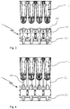
- the transport carrier 12 with the containers 1 is first arranged in a position relative to the aspirator 2 as is shown in Fig. 2 and Fig. 3 , so that the bottom 11 of each individual container 1 is arranged above a corresponding suction cup 21 of the respective aspirator 2.
- the suction cup 21 of the respective aspirator 2 is then lifted towards the bottom 11 of the respective container 1 into a position which is shown in Fig. 4 ,
- the aspirator 2 comprises a suction cup 21 having a central suction orifice 24 in the center of a concave wall 22 of the suction cup 21 allowing to apply suction to the convex bottom 11 of the container 1.
- the concave wall 22 of the suction cup 21 has a shape which corresponds to the convex shape of the bottom 11 of the container 1, so that the convexly shaped bottom 11 of the container 1 is accommodated in a cavity bounded by the concave wall 22 of the suction cup 21.
- the positioner 4 comprises an actuator for linearly moving the suction cup 21 from a retracted position ( Fig. 3 ) towards the bottom 11 of the container 1 until reaching a suction position ( Fig. 4 ). This movement may be performed with the aid of a pneumatic linear drive, which is comprised by the positioner 4 shown in Fig. 1 . This upward movement of the suction cup 21 is also indicated by the arrow shown in Fig. 5 .
- the concave wall 22 of the suction cup 21 is arranged in the closed vicinity of the convex bottom 11 of the container 1 but does not contact the bottom 11 of the container 1. Rather, there is a small gap between the concave wall 22 of the suction cup 21 and the convexly shaped bottom 11 of the container 1 in order to allow for air to flow through that small gap formed between the concave wall 22 of the suction cup 21 and the convexly shaped bottom 11 of the container 1.
- the small gap allows for a leakage stream of air to enter between the concave wall 22 of the suction cup 21 and the convex bottom 11 of the container 1.
- This leakage stream flows towards the central suction orifice 24 in the concave wall 22 of the suction cup 21 and helps to transport liquid remaining on the surface of the bottom 11 of the container 1 and on the contact lens away through the vacuum supply line 23 through which the suction 20 is applied.
- the leakage stream and the suction applied are such that the remaining liquid is efficiently removed without affecting the contact lens accommodated in the container 1.
- the conveyor 3 conveys the transport carrier 12 from the preceding liquid bath 13 to the subsequent liquid bath 14 (see Fig. 1 ).
- the transport carrier 12 with the containers 1 is lifted out of the first liquid bath 13 and is conveyed to position above the aspirators 2.
- the transport of the carrier 12 is intermitted (stopped), and the suction cups 21 are moved vertically towards the bottom 11 of the container 1 (see Fig. 5 ) into the suction position, however, without contacting the bottom 11 of the container 1 (see Fig. 4 ).
- Suction 20 is applied with the aid of a vacuum supply line 23 through the suction orifice 24 arranged in the concave wall 22 of the suction cup 21, as this is shown in Fig. 6 .
- a vacuum supply line 23 Through the application of suction 20, an air stream air is drawn through the small gap formed between the concave wall 22 of the suction cup 21 and the convexly shaped bottom 11 of the container 1 into the suction orifice 24.
- the suction 20 may be applied to the bottom 11 of the container 1 through the suction orifice 24 in the concave wall 22 of the suction cup 21 during a time period in the range of 0.5 seconds to 2 seconds, at a suction (underpressure) in the range of up to 900 hPa (corresponding to 900 millibars), in particular in the range of 350 hPa to 750 hPa (corresponding to 350 millibars to 750 millibars).
- the suction cups 21 are lowered again, and movement of the transport carrier 12 with the containers 1 accommodating the contact lenses towards and into the subsequent liquid bath 14 is resumed.
- any liquid adhering to the bottom 11 of the container or to the contact lenses is reliably drawn in through the suction orifice 24 together with the air stream, so that there is no liquid anymore that can be carried-over to the subsequent bath 14 or that can be spilled.
Landscapes
- Engineering & Computer Science (AREA)
- Health & Medical Sciences (AREA)
- Mechanical Engineering (AREA)
- Manufacturing & Machinery (AREA)
- Ophthalmology & Optometry (AREA)
- Life Sciences & Earth Sciences (AREA)
- Chemical & Material Sciences (AREA)
- Chemical Kinetics & Catalysis (AREA)
- General Chemical & Material Sciences (AREA)
- General Engineering & Computer Science (AREA)
- Molecular Biology (AREA)
- Epidemiology (AREA)
- Animal Behavior & Ethology (AREA)
- General Health & Medical Sciences (AREA)
- Public Health (AREA)
- Veterinary Medicine (AREA)
- Eyeglasses (AREA)
Claims (6)
- Verfahren zum Entfernen einer Flüssigkeit, die an einem konvexen Boden (11) eines Behälters (1) zur Aufnahme einer ophthalmischen Linse, insbesondere einer Kontaktlinse, wie einer weichen Kontaktlinse haftet, wodurch der Fluss von Flüssigkeit in den Behälter (1) hinein und aus diesem heraus ermöglicht wird, während des Transportierens des Behälters (1) von einem Flüssigkeitsbad (13) zu einer nachfolgenden Verarbeitungsstation (14), wobei das Verfahren die Schritte umfasst:- Transportieren des Behälters (1) von dem Flüssigkeitsbad (13) zu der nachfolgenden Verarbeitungsstation (14),- Bereitstellen eines Aspirators (2), der einen Sauggreifer (21) mit einer konkaven Wand (22) mit mindestens einer Saugöffnung (24) umfasst, die in der konkaven Wand (22) angeordnet ist, wobei die konkave Wand des Sauggreifers (21) eine Form hat, die mit der Form des konvexen Bodens (11) des Behälters korrespondiert,- Generieren von Saugkraft (20),- Anwenden der Saugkraft (20) durch die mindestens eine Saugöffnung (24) hindurch, die in der konkaven Wand (22) des Sauggreifers (21) angeordnet ist,- Bewegen des Sauggreifers (21) in Richtung des konvexen Bodens (11) des Behälters (1), wobei die konkave Wand (22) des Sauggreifers (21) zu dem konvexen Boden (11) des Behälters (1) weist,- Anwenden der Saugkraft (20) auf den konvexen Boden (11) des Behälters (1) während des Schrittes des Transportierens des Behälters (1) von dem Flüssigkeitsbad zu der nachfolgenden Verarbeitungsstation, wodurch die Flüssigkeit, die an dem konvexen Boden des Behälters haftet, von dem Behälter entfernt wird,- wobei der Sauggreifer (21) nur in einem Maße in Richtung des konvexen Bodens (11) des Behälters (1) bewegt wird, dass der Sauggreifer (21) den konvexen Boden (11) des Behälters (1) nicht kontaktiert, und- wobei Anwenden der Saugkraft (20) auf den konvexen Boden (11) des Behälters (1) ermöglicht, dass ein Leckagestrom zwischen dem Boden (11) des Behälters (1) und der konkaven Wand (22) des Sauggreifers (21) in Richtung der mindestens einen Saugöffnung (24) in der konkaven Wand (22) des Sauggreifers (21) fließt.
- Verfahren nach Anspruch 1, wobei die Saugkraft (20) während eines Zeitraums im Bereich von 0,5 Sekunden bis 2 Sekunden auf den Boden (11) des Behälters (1) angewendet wird.
- Verfahren nach einem der vorhergehenden Ansprüche, wobei die Saugkraft (20) im Bereich von bis zu 900 hPa, insbesondere im Bereich von 350 hPa bis 750 hPa liegt.
- Verfahren nach einem der vorhergehenden Ansprüche, wobei der Transport des Behälters (1) von dem Flüssigkeitsbad (21) zu der nachfolgenden Verarbeitungsstation intermittierend bewirkt wird, und wobei Saugkraft auf den Boden (11) des Behälters (1) zu der Zeit angewendet wird, in welcher der Transport des Behälters (1) unterbrochen ist.
- System zum Entfernen einer Flüssigkeit, die an einem konvexen Boden (11) eines Behälters zur Aufnahme einer ophthalmischen Linse, insbesondere einer Kontaktlinse, wie einer weichen Kontaktlinse haftet, wodurch der Fluss von Flüssigkeit in den Behälter hinein und aus diesem heraus ermöglicht wird, während des Transportierens des Behälters (1) von einem Flüssigkeitsbad (13) zu einer nachfolgenden Verarbeitungsstation (14), wobei das System umfasst:- einen Transportträger (12), umfassend einen Behälter (1) mit dem konvexen Boden (11),- eine Förderanlage (3) zum Transportieren des Transportträgers (12) von einem Flüssigkeitsbad (13) zu einer nachfolgenden Verarbeitungsstation (14),- einen Aspirator (2), umfassend einen Sauggreifer (21), der mit einer Vakuumzufuhrleitung (23) verbunden ist, um Saugkraft (20) auf den konvexen Boden (11) des Behälters (1) anzuwenden, wobei der Sauggreifer (21) des Aspirators (2) eine konkave Wand (22) mit mindestens einer Saugöffnung (24) aufweist, die in der konkaven Wand (22) angeordnet ist, wobei die konvexe Form des Bodens (11) des Behälters (1) und die Form der konkaven Wand (22) des Sauggreifers miteinander korrespondieren, um den konvex geformten Boden (11) des Behälters (1) in einem Hohlraum aufzunehmen, der von der konkaven Wand (22) des Sauggreifers (21) umgrenzt wird, und- einen Positionierer (4) zum Anordnen des Behälters (1) relativ zu dem Sauggreifer (21), so dass der Boden (11) des Behälters (1) der Saugkraft (20) exponiert wird, die durch den Sauggreifer (21) während des Betriebs angewendet wird, um die Flüssigkeit von dem Behälter (1) zu entfernen,wobei der Positionierer (4) einen Aktor zum linearen Bewegen des Sauggreifers (21) des Aspirators (2) in Richtung des konvexen Bodens (11) des Behälters (1) und von diesem weg umfasst.
- System nach Anspruch 5, wobei der Aktor ein pneumatischer Linearantrieb ist.
Applications Claiming Priority (2)
| Application Number | Priority Date | Filing Date | Title |
|---|---|---|---|
| US201562266034P | 2015-12-11 | 2015-12-11 | |
| PCT/IB2016/056847 WO2017098354A1 (en) | 2015-12-11 | 2016-11-14 | Method and system for removing a liquid from a container for accommodating an ophthalmic lens |
Publications (2)
| Publication Number | Publication Date |
|---|---|
| EP3386739A1 EP3386739A1 (de) | 2018-10-17 |
| EP3386739B1 true EP3386739B1 (de) | 2022-05-25 |
Family
ID=57392015
Family Applications (1)
| Application Number | Title | Priority Date | Filing Date |
|---|---|---|---|
| EP16801053.6A Active EP3386739B1 (de) | 2015-12-11 | 2016-11-14 | Verfahren und system zum entfernen einer flüssigkeit aus einem behälter zur aufnahme eines brillenglases |
Country Status (7)
| Country | Link |
|---|---|
| US (2) | US10195303B2 (de) |
| EP (1) | EP3386739B1 (de) |
| CN (1) | CN108367516B (de) |
| HU (1) | HUE058913T2 (de) |
| MY (1) | MY187888A (de) |
| SG (1) | SG11201804027RA (de) |
| WO (1) | WO2017098354A1 (de) |
Families Citing this family (1)
| Publication number | Priority date | Publication date | Assignee | Title |
|---|---|---|---|---|
| HUE058913T2 (hu) * | 2015-12-11 | 2022-09-28 | Alcon Inc | Eljárás folyadék eltávolítására |
Citations (1)
| Publication number | Priority date | Publication date | Assignee | Title |
|---|---|---|---|---|
| US20120126558A1 (en) * | 2010-11-19 | 2012-05-24 | Laessig Guenter | Gripper for grasping an ophthalmic lens immersed in a liquid |
Family Cites Families (12)
| Publication number | Priority date | Publication date | Assignee | Title |
|---|---|---|---|---|
| IL108992A (en) * | 1993-03-29 | 1997-11-20 | Johnson & Johnson Vision Prod | Solution removal nozzle |
| US5578331A (en) | 1994-06-10 | 1996-11-26 | Vision Products, Inc. | Automated apparatus for preparing contact lenses for inspection and packaging |
| US5561970A (en) * | 1995-06-21 | 1996-10-08 | Johnson & Johnson Vision Products, Inc. | Automated robotic lens load system |
| JP3244220B2 (ja) * | 1996-08-06 | 2002-01-07 | 信越半導体株式会社 | 平板状物の乾燥方法および乾燥装置 |
| US6068798A (en) * | 1998-09-03 | 2000-05-30 | Bausch & Lomb Incorporated | Lens hydration apparatus and method |
| US20040074525A1 (en) * | 2001-03-27 | 2004-04-22 | Widman Michael F. | Transfer apparatus and method and a transfer apparatus cleaner and method |
| US20060272297A1 (en) * | 2003-06-27 | 2006-12-07 | Mcfarlane John | Package drying apparatus and method |
| WO2011045384A1 (en) | 2009-10-16 | 2011-04-21 | Novartis Ag | Container for the accommodation of a contact lens |
| EP2488351B1 (de) | 2009-10-16 | 2016-05-04 | Novartis AG | Vorrichtung und verfahren für den transport von kontaktlinsen durch tauchbäder |
| DE102013009344A1 (de) * | 2013-06-04 | 2014-12-04 | Festo Ag & Co. Kg | Sauggreifer |
| EP3043988A1 (de) * | 2013-09-11 | 2016-07-20 | Novartis AG | Greifinstrument für eine kontaktlinse und verfahren für den transport einer kontaktlinse |
| HUE058913T2 (hu) * | 2015-12-11 | 2022-09-28 | Alcon Inc | Eljárás folyadék eltávolítására |
-
2016
- 2016-11-14 HU HUE16801053A patent/HUE058913T2/hu unknown
- 2016-11-14 SG SG11201804027RA patent/SG11201804027RA/en unknown
- 2016-11-14 CN CN201680071221.5A patent/CN108367516B/zh active Active
- 2016-11-14 MY MYPI2018000748A patent/MY187888A/en unknown
- 2016-11-14 US US15/350,374 patent/US10195303B2/en active Active
- 2016-11-14 WO PCT/IB2016/056847 patent/WO2017098354A1/en not_active Ceased
- 2016-11-14 EP EP16801053.6A patent/EP3386739B1/de active Active
-
2018
- 2018-12-20 US US16/226,990 patent/US10624981B2/en active Active
Patent Citations (1)
| Publication number | Priority date | Publication date | Assignee | Title |
|---|---|---|---|---|
| US20120126558A1 (en) * | 2010-11-19 | 2012-05-24 | Laessig Guenter | Gripper for grasping an ophthalmic lens immersed in a liquid |
Also Published As
| Publication number | Publication date |
|---|---|
| MY187888A (en) | 2021-10-26 |
| US20190117821A1 (en) | 2019-04-25 |
| SG11201804027RA (en) | 2018-06-28 |
| HUE058913T2 (hu) | 2022-09-28 |
| US10624981B2 (en) | 2020-04-21 |
| WO2017098354A1 (en) | 2017-06-15 |
| CN108367516A (zh) | 2018-08-03 |
| CN108367516B (zh) | 2021-01-29 |
| EP3386739A1 (de) | 2018-10-17 |
| US20170165393A1 (en) | 2017-06-15 |
| US10195303B2 (en) | 2019-02-05 |
Similar Documents
| Publication | Publication Date | Title |
|---|---|---|
| CA2298723C (en) | Contact lens transfer and material removal system | |
| US9840047B2 (en) | Apparatus and method for transporting contact lenses through dipping baths | |
| EP2640568B1 (de) | Greifer zum erfassen einer in eine flüssigkeit getauchten ophthalmischen linse | |
| US10624981B2 (en) | Method and system for removing a liquid from a container for accommodating an ophthalmic lens | |
| US10053249B2 (en) | Method for transporting a packaging shell of an ophthalmic lens package | |
| JP4862993B2 (ja) | 薄肉ボトルへの充填・密封方法 | |
| CN104602841A (zh) | 在制造之后并在组装为注射器、插管等之前清洁多个针状物 | |
| JP2004281978A (ja) | キャリアボックスの自動洗浄装置および自動洗浄方法 | |
| JP2002193223A (ja) | フィルム殺菌装置 | |
| JP2010034211A (ja) | 半導体ウェーハ並びにその洗浄装置及びその洗浄方法 | |
| JP2009178771A (ja) | 合成樹脂被覆絞りしごき金属缶体の製造方法及び製造装置 | |
| JP2008300451A (ja) | 搬送装置並びに液処理装置及び同液処理装置における被処理体の搬送方法 | |
| WO2026047572A1 (en) | Ophthalmic lens gripper | |
| JP2005317708A (ja) | ウエーハの洗浄装置及びウエーハの洗浄方法 | |
| JP2005081279A (ja) | ワーク表面処理装置 | |
| WO2020089809A1 (en) | Treatment container for accommodating an ophthalmic lens, container plate, container tray and method for treatment of an ophthalmic lens | |
| JP2009108367A (ja) | 処理槽切替え方式の表面処理装置、この表面処理装置に用いる可動式液受け装置 | |
| JP2002219538A (ja) | 合成樹脂被覆絞りしごき金属缶体の製造方法及び装置 | |
| JP2018024175A (ja) | 合成樹脂製ボトルの仕上げ処理機 | |
| KR20180001805U (ko) | 이송 롤러, 이송 장치 및 기판 처리 시스템 | |
| HK1028006B (en) | Contact lens transfer and material removal system | |
| JP2004277169A (ja) | 物品の自動搬送装置および自動搬送方法 |
Legal Events
| Date | Code | Title | Description |
|---|---|---|---|
| STAA | Information on the status of an ep patent application or granted ep patent |
Free format text: STATUS: UNKNOWN |
|
| STAA | Information on the status of an ep patent application or granted ep patent |
Free format text: STATUS: THE INTERNATIONAL PUBLICATION HAS BEEN MADE |
|
| PUAI | Public reference made under article 153(3) epc to a published international application that has entered the european phase |
Free format text: ORIGINAL CODE: 0009012 |
|
| STAA | Information on the status of an ep patent application or granted ep patent |
Free format text: STATUS: REQUEST FOR EXAMINATION WAS MADE |
|
| 17P | Request for examination filed |
Effective date: 20180703 |
|
| AK | Designated contracting states |
Kind code of ref document: A1 Designated state(s): AL AT BE BG CH CY CZ DE DK EE ES FI FR GB GR HR HU IE IS IT LI LT LU LV MC MK MT NL NO PL PT RO RS SE SI SK SM TR |
|
| AX | Request for extension of the european patent |
Extension state: BA ME |
|
| DAV | Request for validation of the european patent (deleted) | ||
| DAX | Request for extension of the european patent (deleted) | ||
| RAP1 | Party data changed (applicant data changed or rights of an application transferred) |
Owner name: ALCON INC. |
|
| STAA | Information on the status of an ep patent application or granted ep patent |
Free format text: STATUS: EXAMINATION IS IN PROGRESS |
|
| STAA | Information on the status of an ep patent application or granted ep patent |
Free format text: STATUS: REQUEST FOR EXAMINATION WAS MADE |
|
| 17Q | First examination report despatched |
Effective date: 20211108 |
|
| GRAP | Despatch of communication of intention to grant a patent |
Free format text: ORIGINAL CODE: EPIDOSNIGR1 |
|
| STAA | Information on the status of an ep patent application or granted ep patent |
Free format text: STATUS: GRANT OF PATENT IS INTENDED |
|
| INTG | Intention to grant announced |
Effective date: 20211223 |
|
| GRAS | Grant fee paid |
Free format text: ORIGINAL CODE: EPIDOSNIGR3 |
|
| GRAA | (expected) grant |
Free format text: ORIGINAL CODE: 0009210 |
|
| STAA | Information on the status of an ep patent application or granted ep patent |
Free format text: STATUS: THE PATENT HAS BEEN GRANTED |
|
| AK | Designated contracting states |
Kind code of ref document: B1 Designated state(s): AL AT BE BG CH CY CZ DE DK EE ES FI FR GB GR HR HU IE IS IT LI LT LU LV MC MK MT NL NO PL PT RO RS SE SI SK SM TR |
|
| REG | Reference to a national code |
Ref country code: GB Ref legal event code: FG4D |
|
| REG | Reference to a national code |
Ref country code: CH Ref legal event code: EP |
|
| REG | Reference to a national code |
Ref country code: AT Ref legal event code: REF Ref document number: 1494093 Country of ref document: AT Kind code of ref document: T Effective date: 20220615 Ref country code: DE Ref legal event code: R096 Ref document number: 602016072403 Country of ref document: DE |
|
| REG | Reference to a national code |
Ref country code: IE Ref legal event code: FG4D |
|
| REG | Reference to a national code |
Ref country code: LT Ref legal event code: MG9D |
|
| REG | Reference to a national code |
Ref country code: NL Ref legal event code: MP Effective date: 20220525 Ref country code: HU Ref legal event code: AG4A Ref document number: E058913 Country of ref document: HU |
|
| REG | Reference to a national code |
Ref country code: AT Ref legal event code: MK05 Ref document number: 1494093 Country of ref document: AT Kind code of ref document: T Effective date: 20220525 |
|
| PG25 | Lapsed in a contracting state [announced via postgrant information from national office to epo] |
Ref country code: SE Free format text: LAPSE BECAUSE OF FAILURE TO SUBMIT A TRANSLATION OF THE DESCRIPTION OR TO PAY THE FEE WITHIN THE PRESCRIBED TIME-LIMIT Effective date: 20220525 Ref country code: PT Free format text: LAPSE BECAUSE OF FAILURE TO SUBMIT A TRANSLATION OF THE DESCRIPTION OR TO PAY THE FEE WITHIN THE PRESCRIBED TIME-LIMIT Effective date: 20220926 Ref country code: NO Free format text: LAPSE BECAUSE OF FAILURE TO SUBMIT A TRANSLATION OF THE DESCRIPTION OR TO PAY THE FEE WITHIN THE PRESCRIBED TIME-LIMIT Effective date: 20220825 Ref country code: NL Free format text: LAPSE BECAUSE OF FAILURE TO SUBMIT A TRANSLATION OF THE DESCRIPTION OR TO PAY THE FEE WITHIN THE PRESCRIBED TIME-LIMIT Effective date: 20220525 Ref country code: LT Free format text: LAPSE BECAUSE OF FAILURE TO SUBMIT A TRANSLATION OF THE DESCRIPTION OR TO PAY THE FEE WITHIN THE PRESCRIBED TIME-LIMIT Effective date: 20220525 Ref country code: HR Free format text: LAPSE BECAUSE OF FAILURE TO SUBMIT A TRANSLATION OF THE DESCRIPTION OR TO PAY THE FEE WITHIN THE PRESCRIBED TIME-LIMIT Effective date: 20220525 Ref country code: GR Free format text: LAPSE BECAUSE OF FAILURE TO SUBMIT A TRANSLATION OF THE DESCRIPTION OR TO PAY THE FEE WITHIN THE PRESCRIBED TIME-LIMIT Effective date: 20220826 Ref country code: FI Free format text: LAPSE BECAUSE OF FAILURE TO SUBMIT A TRANSLATION OF THE DESCRIPTION OR TO PAY THE FEE WITHIN THE PRESCRIBED TIME-LIMIT Effective date: 20220525 Ref country code: ES Free format text: LAPSE BECAUSE OF FAILURE TO SUBMIT A TRANSLATION OF THE DESCRIPTION OR TO PAY THE FEE WITHIN THE PRESCRIBED TIME-LIMIT Effective date: 20220525 Ref country code: BG Free format text: LAPSE BECAUSE OF FAILURE TO SUBMIT A TRANSLATION OF THE DESCRIPTION OR TO PAY THE FEE WITHIN THE PRESCRIBED TIME-LIMIT Effective date: 20220825 Ref country code: AT Free format text: LAPSE BECAUSE OF FAILURE TO SUBMIT A TRANSLATION OF THE DESCRIPTION OR TO PAY THE FEE WITHIN THE PRESCRIBED TIME-LIMIT Effective date: 20220525 |
|
| PG25 | Lapsed in a contracting state [announced via postgrant information from national office to epo] |
Ref country code: RS Free format text: LAPSE BECAUSE OF FAILURE TO SUBMIT A TRANSLATION OF THE DESCRIPTION OR TO PAY THE FEE WITHIN THE PRESCRIBED TIME-LIMIT Effective date: 20220525 Ref country code: PL Free format text: LAPSE BECAUSE OF FAILURE TO SUBMIT A TRANSLATION OF THE DESCRIPTION OR TO PAY THE FEE WITHIN THE PRESCRIBED TIME-LIMIT Effective date: 20220525 Ref country code: LV Free format text: LAPSE BECAUSE OF FAILURE TO SUBMIT A TRANSLATION OF THE DESCRIPTION OR TO PAY THE FEE WITHIN THE PRESCRIBED TIME-LIMIT Effective date: 20220525 Ref country code: IS Free format text: LAPSE BECAUSE OF FAILURE TO SUBMIT A TRANSLATION OF THE DESCRIPTION OR TO PAY THE FEE WITHIN THE PRESCRIBED TIME-LIMIT Effective date: 20220925 |
|
| PG25 | Lapsed in a contracting state [announced via postgrant information from national office to epo] |
Ref country code: SM Free format text: LAPSE BECAUSE OF FAILURE TO SUBMIT A TRANSLATION OF THE DESCRIPTION OR TO PAY THE FEE WITHIN THE PRESCRIBED TIME-LIMIT Effective date: 20220525 Ref country code: SK Free format text: LAPSE BECAUSE OF FAILURE TO SUBMIT A TRANSLATION OF THE DESCRIPTION OR TO PAY THE FEE WITHIN THE PRESCRIBED TIME-LIMIT Effective date: 20220525 Ref country code: RO Free format text: LAPSE BECAUSE OF FAILURE TO SUBMIT A TRANSLATION OF THE DESCRIPTION OR TO PAY THE FEE WITHIN THE PRESCRIBED TIME-LIMIT Effective date: 20220525 Ref country code: EE Free format text: LAPSE BECAUSE OF FAILURE TO SUBMIT A TRANSLATION OF THE DESCRIPTION OR TO PAY THE FEE WITHIN THE PRESCRIBED TIME-LIMIT Effective date: 20220525 Ref country code: DK Free format text: LAPSE BECAUSE OF FAILURE TO SUBMIT A TRANSLATION OF THE DESCRIPTION OR TO PAY THE FEE WITHIN THE PRESCRIBED TIME-LIMIT Effective date: 20220525 Ref country code: CZ Free format text: LAPSE BECAUSE OF FAILURE TO SUBMIT A TRANSLATION OF THE DESCRIPTION OR TO PAY THE FEE WITHIN THE PRESCRIBED TIME-LIMIT Effective date: 20220525 |
|
| REG | Reference to a national code |
Ref country code: DE Ref legal event code: R097 Ref document number: 602016072403 Country of ref document: DE |
|
| PG25 | Lapsed in a contracting state [announced via postgrant information from national office to epo] |
Ref country code: AL Free format text: LAPSE BECAUSE OF FAILURE TO SUBMIT A TRANSLATION OF THE DESCRIPTION OR TO PAY THE FEE WITHIN THE PRESCRIBED TIME-LIMIT Effective date: 20220525 |
|
| PLBE | No opposition filed within time limit |
Free format text: ORIGINAL CODE: 0009261 |
|
| STAA | Information on the status of an ep patent application or granted ep patent |
Free format text: STATUS: NO OPPOSITION FILED WITHIN TIME LIMIT |
|
| 26N | No opposition filed |
Effective date: 20230228 |
|
| PG25 | Lapsed in a contracting state [announced via postgrant information from national office to epo] |
Ref country code: SI Free format text: LAPSE BECAUSE OF FAILURE TO SUBMIT A TRANSLATION OF THE DESCRIPTION OR TO PAY THE FEE WITHIN THE PRESCRIBED TIME-LIMIT Effective date: 20220525 |
|
| P01 | Opt-out of the competence of the unified patent court (upc) registered |
Effective date: 20230505 |
|
| PG25 | Lapsed in a contracting state [announced via postgrant information from national office to epo] |
Ref country code: MC Free format text: LAPSE BECAUSE OF FAILURE TO SUBMIT A TRANSLATION OF THE DESCRIPTION OR TO PAY THE FEE WITHIN THE PRESCRIBED TIME-LIMIT Effective date: 20220525 |
|
| REG | Reference to a national code |
Ref country code: CH Ref legal event code: PL |
|
| REG | Reference to a national code |
Ref country code: BE Ref legal event code: MM Effective date: 20221130 |
|
| PG25 | Lapsed in a contracting state [announced via postgrant information from national office to epo] |
Ref country code: LI Free format text: LAPSE BECAUSE OF NON-PAYMENT OF DUE FEES Effective date: 20221130 Ref country code: CH Free format text: LAPSE BECAUSE OF NON-PAYMENT OF DUE FEES Effective date: 20221130 |
|
| PG25 | Lapsed in a contracting state [announced via postgrant information from national office to epo] |
Ref country code: LU Free format text: LAPSE BECAUSE OF NON-PAYMENT OF DUE FEES Effective date: 20221114 |
|
| PG25 | Lapsed in a contracting state [announced via postgrant information from national office to epo] |
Ref country code: FR Free format text: LAPSE BECAUSE OF NON-PAYMENT OF DUE FEES Effective date: 20221130 Ref country code: BE Free format text: LAPSE BECAUSE OF NON-PAYMENT OF DUE FEES Effective date: 20221130 |
|
| PG25 | Lapsed in a contracting state [announced via postgrant information from national office to epo] |
Ref country code: IT Free format text: LAPSE BECAUSE OF FAILURE TO SUBMIT A TRANSLATION OF THE DESCRIPTION OR TO PAY THE FEE WITHIN THE PRESCRIBED TIME-LIMIT Effective date: 20220525 |
|
| PG25 | Lapsed in a contracting state [announced via postgrant information from national office to epo] |
Ref country code: CY Free format text: LAPSE BECAUSE OF FAILURE TO SUBMIT A TRANSLATION OF THE DESCRIPTION OR TO PAY THE FEE WITHIN THE PRESCRIBED TIME-LIMIT Effective date: 20220525 |
|
| PG25 | Lapsed in a contracting state [announced via postgrant information from national office to epo] |
Ref country code: MK Free format text: LAPSE BECAUSE OF FAILURE TO SUBMIT A TRANSLATION OF THE DESCRIPTION OR TO PAY THE FEE WITHIN THE PRESCRIBED TIME-LIMIT Effective date: 20220525 |
|
| PG25 | Lapsed in a contracting state [announced via postgrant information from national office to epo] |
Ref country code: TR Free format text: LAPSE BECAUSE OF FAILURE TO SUBMIT A TRANSLATION OF THE DESCRIPTION OR TO PAY THE FEE WITHIN THE PRESCRIBED TIME-LIMIT Effective date: 20220525 |
|
| PG25 | Lapsed in a contracting state [announced via postgrant information from national office to epo] |
Ref country code: MT Free format text: LAPSE BECAUSE OF FAILURE TO SUBMIT A TRANSLATION OF THE DESCRIPTION OR TO PAY THE FEE WITHIN THE PRESCRIBED TIME-LIMIT Effective date: 20220525 |
|
| PG25 | Lapsed in a contracting state [announced via postgrant information from national office to epo] |
Ref country code: BG Free format text: LAPSE BECAUSE OF FAILURE TO SUBMIT A TRANSLATION OF THE DESCRIPTION OR TO PAY THE FEE WITHIN THE PRESCRIBED TIME-LIMIT Effective date: 20220525 |
|
| PG25 | Lapsed in a contracting state [announced via postgrant information from national office to epo] |
Ref country code: BG Free format text: LAPSE BECAUSE OF FAILURE TO SUBMIT A TRANSLATION OF THE DESCRIPTION OR TO PAY THE FEE WITHIN THE PRESCRIBED TIME-LIMIT Effective date: 20220525 |
|
| PGFP | Annual fee paid to national office [announced via postgrant information from national office to epo] |
Ref country code: HU Payment date: 20251112 Year of fee payment: 10 |
|
| PGFP | Annual fee paid to national office [announced via postgrant information from national office to epo] |
Ref country code: DE Payment date: 20251022 Year of fee payment: 10 |
|
| PGFP | Annual fee paid to national office [announced via postgrant information from national office to epo] |
Ref country code: GB Payment date: 20251016 Year of fee payment: 10 |
|
| PGFP | Annual fee paid to national office [announced via postgrant information from national office to epo] |
Ref country code: IE Payment date: 20251024 Year of fee payment: 10 |