EP3386077B1 - Boîtier de connexion de moteur et moteur de convertisseur - Google Patents
Boîtier de connexion de moteur et moteur de convertisseur Download PDFInfo
- Publication number
- EP3386077B1 EP3386077B1 EP18000333.7A EP18000333A EP3386077B1 EP 3386077 B1 EP3386077 B1 EP 3386077B1 EP 18000333 A EP18000333 A EP 18000333A EP 3386077 B1 EP3386077 B1 EP 3386077B1
- Authority
- EP
- European Patent Office
- Prior art keywords
- motor
- junction box
- circuit board
- tubular part
- box according
- Prior art date
- Legal status (The legal status is an assumption and is not a legal conclusion. Google has not performed a legal analysis and makes no representation as to the accuracy of the status listed.)
- Active
Links
- 239000003990 capacitor Substances 0.000 claims description 15
- 230000003247 decreasing effect Effects 0.000 claims description 8
- 210000002105 tongue Anatomy 0.000 claims description 6
- 238000005266 casting Methods 0.000 claims description 3
- 230000017525 heat dissipation Effects 0.000 claims description 3
- 238000001816 cooling Methods 0.000 description 12
- 238000004891 communication Methods 0.000 description 6
- 238000005452 bending Methods 0.000 description 4
- 150000001875 compounds Chemical class 0.000 description 4
- 238000004382 potting Methods 0.000 description 4
- 238000013459 approach Methods 0.000 description 3
- 238000005520 cutting process Methods 0.000 description 3
- 238000013461 design Methods 0.000 description 3
- 238000009434 installation Methods 0.000 description 3
- 230000015572 biosynthetic process Effects 0.000 description 2
- 230000001276 controlling effect Effects 0.000 description 2
- 230000008878 coupling Effects 0.000 description 2
- 238000010168 coupling process Methods 0.000 description 2
- 238000005859 coupling reaction Methods 0.000 description 2
- 238000004519 manufacturing process Methods 0.000 description 2
- 238000003825 pressing Methods 0.000 description 2
- 230000002787 reinforcement Effects 0.000 description 2
- 238000007789 sealing Methods 0.000 description 2
- 241000555745 Sciuridae Species 0.000 description 1
- XAGFODPZIPBFFR-UHFFFAOYSA-N aluminium Chemical compound [Al] XAGFODPZIPBFFR-UHFFFAOYSA-N 0.000 description 1
- 229910052782 aluminium Inorganic materials 0.000 description 1
- 230000004323 axial length Effects 0.000 description 1
- 230000004888 barrier function Effects 0.000 description 1
- 230000005540 biological transmission Effects 0.000 description 1
- 230000000295 complement effect Effects 0.000 description 1
- 238000010276 construction Methods 0.000 description 1
- 230000007423 decrease Effects 0.000 description 1
- 238000003745 diagnosis Methods 0.000 description 1
- 229920001971 elastomer Polymers 0.000 description 1
- 239000000806 elastomer Substances 0.000 description 1
- 238000010348 incorporation Methods 0.000 description 1
- 238000003780 insertion Methods 0.000 description 1
- 230000037431 insertion Effects 0.000 description 1
- 230000010354 integration Effects 0.000 description 1
- 239000007788 liquid Substances 0.000 description 1
- 238000012423 maintenance Methods 0.000 description 1
- 239000000463 material Substances 0.000 description 1
- 230000001681 protective effect Effects 0.000 description 1
- 230000001105 regulatory effect Effects 0.000 description 1
- 239000004065 semiconductor Substances 0.000 description 1
- 238000005476 soldering Methods 0.000 description 1
- 238000004804 winding Methods 0.000 description 1
Images


Classifications
-
- H—ELECTRICITY
- H02—GENERATION; CONVERSION OR DISTRIBUTION OF ELECTRIC POWER
- H02K—DYNAMO-ELECTRIC MACHINES
- H02K5/00—Casings; Enclosures; Supports
- H02K5/04—Casings or enclosures characterised by the shape, form or construction thereof
- H02K5/22—Auxiliary parts of casings not covered by groups H02K5/06-H02K5/20, e.g. shaped to form connection boxes or terminal boxes
- H02K5/225—Terminal boxes or connection arrangements
-
- H—ELECTRICITY
- H02—GENERATION; CONVERSION OR DISTRIBUTION OF ELECTRIC POWER
- H02K—DYNAMO-ELECTRIC MACHINES
- H02K11/00—Structural association of dynamo-electric machines with electric components or with devices for shielding, monitoring or protection
- H02K11/30—Structural association with control circuits or drive circuits
- H02K11/33—Drive circuits, e.g. power electronics
-
- H—ELECTRICITY
- H02—GENERATION; CONVERSION OR DISTRIBUTION OF ELECTRIC POWER
- H02K—DYNAMO-ELECTRIC MACHINES
- H02K5/00—Casings; Enclosures; Supports
- H02K5/04—Casings or enclosures characterised by the shape, form or construction thereof
- H02K5/20—Casings or enclosures characterised by the shape, form or construction thereof with channels or ducts for flow of cooling medium
- H02K5/207—Casings or enclosures characterised by the shape, form or construction thereof with channels or ducts for flow of cooling medium with openings in the casing specially adapted for ambient air
-
- H—ELECTRICITY
- H02—GENERATION; CONVERSION OR DISTRIBUTION OF ELECTRIC POWER
- H02K—DYNAMO-ELECTRIC MACHINES
- H02K9/00—Arrangements for cooling or ventilating
- H02K9/14—Arrangements for cooling or ventilating wherein gaseous cooling medium circulates between the machine casing and a surrounding mantle
Definitions
- a converter motor is understood to mean an electrically operated drive unit which comprises at least one motor unit and an electronic assembly, the converter unit, for controlling the motor unit, in particular for regulating the speed and / or the torque.
- the motor unit can here comprise a permanently excited rotor, a squirrel cage rotor or a combination of both, or it can be designed as an external rotor.
- the utility model G 94 15 934.3 discloses a pump unit with a pump housing.
- One side of the pump housing has a flat connection surface on which a terminal box made of plastic is detachably attached.
- the terminal box is constructed in two parts and consists of a housing part that is essentially closed on five sides and a cover with which the housing part can be tightly sealed, if necessary with the incorporation of a seal.
- the cover is fixed to the housing part by means of an externally accessible screw.
- the patent specification DE 44 35 510 C1 discloses a pump unit with a pump housing, a motor housing and a terminal box.
- a body part can be locked from the outside with two ribbed covers.
- the body part comprises the terminal box floor and four side walls which are directed approximately radially to the motor axis.
- the pamphlet JP H06 57067 U discloses an electric motor with a housing, on the outside of which a connection card is fastened by means of a screw.
- the connection box has a projection which is arranged in a correspondingly shaped receptacle in the housing.
- the cable connection device has at least two insertion openings for cables.
- the cable connection device has a connection box made up of two trough-like sub-boxes.
- the utility model DE 73 42 532 U discloses a motor with two terminal boxes, the interior of one of the two terminal boxes communicating with the interior of the motor.
- a motor which has a housing in which electronic devices for controlling the motor are accommodated.
- the housing has sections which are axially and vertically connected to the motor and which form a structural unit with a connection box cover and a fan cover of the motor.
- connection box for a motor is known.
- the connection box has a cover cap with a recess, the recess being suitable for receiving the body of a commercially available plug-in coupling or socket.
- an electric motor with a terminal box is disclosed, with a heat conducting plate located in an opening in a wall area of the terminal box, which carries power electronics on its side facing away from the motor housing.
- an electric motor with a power unit is known, the components of which are mounted on a carrier body suitable for high currents and for sufficient dissipation of the power loss.
- the electric motor has a housing with an outer wall in which a recess is provided which corresponds to a recess in an electronics module housing, with a recess in the recess Radiator insert is introduced such that it rests against the inner wall of the electric motor housing.
- connection box having a connection for a power supply.
- the invention is based on the object of developing a motor junction box and a converter motor in order to not only improve heat dissipation but also to protect large electronic components that are housed in a motor junction box when the cover of the box is removed, and at the same time to reduce the overall height of the motor junction box to reduce.
- the object is achieved with the motor connection box according to the features specified in claim 1 and with the converter motor with the features specified in claim 14.
- connection means such as connection pieces, connection sockets or connection plugs do not or essentially do not protrude beyond the structural dimensions of the connection box. In this way, on the one hand, a more compact overall dimension and, on the other hand, reliable protection of sensitive parts from impact damage.
- an upper edge is formed on the lower part which runs obliquely from a higher end to a lower end, the incline of the upper edge of the lower part and the step in the upper part having a decreasing height in the same direction.
- the height difference resulting from the design of the step can thus be at least partially used for one-sided elevation of the connection box attachment.
- the step has a plane of symmetry, openings for cable bushings being formed on both sides of the plane of symmetry.
- the plane of symmetry preferably reflects the position of the motor axis when the motor connection box is installed.
- the openings for cable bushings point away from the plane of symmetry. It is thus advantageously achieved that the angular areas which - limited by the bending radius of the connecting cables - are covered by each opening, overlap and complement one another. In particular, cable routing laterally away from the plane of symmetry, that is to say from the motor axis, is thus possible. The motor connection box does not have to be moved for this.
- a first opening for cable bushings is formed in a first flat area of the end face of the step, the mathematical extension of the first flat area intersecting at least two side surfaces of the lower part.
- a second opening for cable bushings is formed in a second flat area of the end face of the step, wherein the mathematical extension of the first flat area intersects at least two side surfaces of the base and the mathematical extension of the first flat area.
- a third opening for cable bushings is formed in a third flat area of the end face of the step, the third opening has a smaller diameter than the second opening and the first opening.
- This provides the option of additional cable routing for communication cables. Since these cables are considerably thinner than the power cables in applications, a smaller bending radius can be selected when laying the cables.
- the third flat area is preferably arranged between the first flat area and the second flat area. It is therefore not necessary to provide openings in several directions. This saves manufacturing steps and improves tightness.
- the first flat area and the second flat area enclose an angle, the tip of which points in the direction of the decreasing height of the step.
- the included angle has an opening angle between 60 ° and 100 °.
- the opening angle of the included angle is preferably 80 °. In this way, advantageous geometric relationships are set with which an overlap of an angular range of more than 270 ° can be used for cable routing.
- converter electronics are provided inside the box. Because the openings for the cable bushings are arranged at an angle to one another, the motor connection box does not have to be converted for a modified cable run.
- the motor connection box is therefore not limited to a square or generally n-cornered basic shape, that is to say a basic shape with more than twofold rotational symmetry, but can for example extend rectangularly over the entire length of a motor housing. Sufficient space is thus available for converter electronics, and the motor connection box is equipped for integration into a compact converter motor.
- the converter electronics include a power component, and a flat support surface is formed on the bottom of the lower part, the power component being placed on the support surface for cooling.
- the housing of the motor connection box can be used for cooling the power components, in particular the IGBTs, which act as a converter output stage take over the control of a motor. This provides a large cooling surface that can be connected to other cooling surfaces.
- the power component is arranged on a circuit board, the circuit board pressing the power component onto the support surface.
- the circuit board is soldered in a first step and the circuit board is inserted into the housing in a second step.
- the power components are attached directly when they are inserted. Additional assembly steps, for example the assembly of a hold-down device, can be dispensed with.
- a fastening frame is provided to which the printed circuit board is fastened and which covers the printed circuit board at the top, openings being formed in the fastening frame through which plug connector parts of the printed circuit board protrude.
- the fastening frame is screwed to the lower part, the fastening frame pressing the printed circuit board against the bottom of the lower part in the locked and / or screwed state.
- An elastomer cushion is preferably arranged between the power components and the circuit board. The contact pressure of the fastening screws for the fastening frame is therefore used to press the power components onto the support surface.
- the fastening frame has a brim, a further printed circuit board being clipped into the brim.
- Resilient tongues with lugs into which the further printed circuit board is clipped are preferably formed in the brim.
- a compact electronic component is thus provided, the first circuit board and the further circuit board being mounted in the lower part before the fastening frame is inserted.
- the two-part design of the electronics also enables the modular replacement of the upper part, i.e. the further printed circuit board, with rectifier and intermediate circuit, for an alternative design, for example without a rectifier.
- a rectifier can namely be dispensed with in the case of a contactless power supply the DE 10 2005 022 367 A1 . All features of a contactless power supply described there are included as part of this description.
- the further circuit board is connected to the connector of the first circuit board via a suitable connector.
- the electronic component consisting of the fastening frame, the first circuit board and the further circuit board can thus be fitted by clipping in.
- the plug connectors are preferably positioned on the circuit boards in such a way that they are connected when they are clipped in. Soldering is therefore no longer necessary. Individual components can easily be replaced during maintenance.
- an intermediate circuit capacitor and / or a rectifier module is arranged on the further printed circuit board in an area which is at least partially surrounded by the higher end of the lower part.
- the step in the upper part in the interior of the motor connection box preferably forms and surrounds an area in which an intermediate circuit capacitor and / or a rectification module of the converter electronics is or are arranged.
- the enclosed installation space formed by the step is thus used for those components that require a lot of space, especially in height.
- the approach of the motor connection box surrounds these components and protects them even with the cover removed.
- the rectifier module and / or intermediate circuit capacitor are designed as options in one embodiment.
- the rectifier module and the intermediate circuit module are preferably comprised by a supply module, for example mounted on a common printed circuit board that is separate from the power output stage.
- the power output stage of the converter electronics is connected directly, without a supply module, to the output of a rectification module of the adapter of a system for contactless energy supply, as it is, for example, in the DE 103 39 340 A1 is described.
- a series of converter motors with different functionality is thus formed.
- an outer tubular part is formed on the lower part for receiving a motor unit, the bottom of the lower part being part of the forms first tubular part.
- the power semiconductors are thus connected to a housing part that acts as a large heat sink.
- an inner tubular part is formed in the outer tubular part for receiving the stator of a motor unit, the axis of the outer tubular part running parallel to the axis of the inner tubular part.
- tubular is generally used to denote a part that is essentially discreetly or continuously rotationally symmetrical about an axis, is hollow on the inside and has a wall thickness that is thin in comparison to the diameter.
- the incline of the upper edge of the lower part has a decreasing height in the direction of the axis of the first tubular part.
- the lower part and the outer tubular part are made from a cast body.
- the formation from a cast part is possible, since the motor connection box does not have to be implemented despite the flexible cable routing option.
- Advantageous cooling is thus achieved, because plug connections or other connections that could act as heat barriers are completely eliminated.
- the outer tubular part and the inner tubular part are made from a cast body, with radially extending webs connecting the two parts.
- This provides a complex motor housing that offers space for a converter that is also cooled by the motor's internal fan.
- the nested arrangement of two housing parts offers the advantage of large cooling surfaces for the motor and converter, which are also thermally decoupled from one another.
- a converter motor is that an inner tubular part is provided which surrounds the stator, and an outer tubular part is provided which surrounds the inner tubular part and on the outside of which a motor connection box is formed according to at least one of the preceding claims, wherein a fan is provided in the outer tubular part which moves air along the inside of the outer tubular part.
- the cooling air between the motor unit and converter unit advantageously causes a thermal decoupling of the two units. The cooling is thus improved.
- the step in the top of the motor connection box advantageously enables more flexible cable routing without the motor connection box having to be rotated or moved. As a result, the motor connection box and motor housing can be manufactured from a single casting. Unfavorable heat transfers through connection points are eliminated. The production is also simplified.
- the incline of the upper edge of the lower part has a decreasing height in the direction of the axis of the outer tubular part, the area of great height being arranged on the drive side of the converter motor.
- the motor connection box preferably extends over the entire axial length of the motor housing. The converter electronics can thus be integrated into the motor housing with the smallest possible overall dimensions.
- the motor shaft is arranged in the plane of symmetry of the motor connection box.
- the converter motor can therefore be connected symmetrically.
- Figure 1 shows a converter motor 1 in side view.
- a tubular outer housing 2 coaxially surrounds a tubular inner housing 3.
- the inner housing 3 contains the motor unit of the converter motor 1.
- the stator of the motor unit is arranged in the inner housing 3 and is held in a force-locking manner by this.
- the inner housing 3 is closed on the drive side of the motor unit by an A-position plate 4, which merges into a gear flange 5.
- the drive side of the motor shaft 15 protrudes through the gear flange 5 for connection to the driving shaft of a gear.
- the outer housing 2 is closed with a fan cover 6 like a grid.
- Inner housing 3 is firmly connected to the outer housing 2 via webs 14.
- Inner housing 3 and outer housing 2 are made from a common cast part. Aluminum is preferably chosen as the material.
- connection box 7 is arranged on the top of the outer housing 2.
- the connection box 7 comprises an upper part designed as a connection box cover 9, which is placed on a lower part, the lower part being formed from a connection box attachment 8 and a region of the outer housing 2.
- the connection box attachment 8 is designed in one piece with the outer housing 2 and surrounds a region of the outer housing 2 which forms the bottom of the connection box 7.
- connection box cover 9 is fastened to the connection box extension by screws 10.
- connection box extension 8 has an inclined upper edge, the height of which is higher above the outer housing 2 on the drive side than at the opposite end of the converter motor 1. Thus, a slope is formed with a sloping height profile that decreases along the motor axis away from the drive side.
- the connection box cover 9 has a corresponding incline. In particular, the angles of the incline with the side walls in the lower part and upper part are the same, so that the side walls essentially merge into one another.
- a step is formed which is formed by the cover top 17 and a shoulder 18 as well as a side surface connecting the two surfaces.
- the upper side of the lid 17 and the shoulder 18 thus each define a plateau of different heights, the shoulder 18 being stepped relative to the upper side 17 of the lid.
- the step forms a height profile that slopes down in the same direction as the incline on the connection box attachment 8.
- the step comprises a side surface 46 on which connecting pieces 12, 13 are arranged for a sealing cable feed-through.
- connection box cover 9 On opposite sides of the connection box cover 9, an axially extending recessed grip 11 is formed, with which the connection box cover 9 can be removed. On the front of the junction box cover 9, a flat bevel 21 is also formed, which merges into the top 17 of the cover.
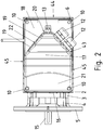
- Figure 2 shows the converter motor 1 from above.
- the inner housing 3 is connected to the outer housing 2 via a cable passage 16.
- the cable passage 16 is used to lead through the connection cables from the connection box to the motor unit.
- the upper side of the cover 17 is delimited by the bevel 21, two lateral side surfaces 45 and the front side of the step, which is formed by flat areas 22, 43 and the front surface 20.
- two openings for cable bushings are made, which can be closed by screw plugs 19 or by connecting pieces 12.
- the first flat area 22 is arranged obliquely to the sides of the connection box attachment 8: the mathematical plane defined by the first flat area 22 in idealization intersects two side surfaces 44, 45 of the connection box attachment 8. Said mathematical level would cut off a corner of the base area of the lower part as a cutting plane . Due to the inclined arrangement of the openings for the cable feed-through, a cable can be led out of the connection box in different directions without the connection box having to be moved. As a result of the step, the area around the openings is protected by protruding housing along and across the motor axis, which relieves the load on the cable routing.
- the side surface of the step comprises a second flat area 43 in which two further openings for the cable feed-through are made. These openings are closed by screwed-in connecting pieces 12.
- the connecting pieces 12 also fit the openings in the first flat area 22.
- the second flat area 43 is also arranged at an angle to the sides of the connection box attachment 8:
- the mathematical plane defined by the second flat area 43 ideally intersects two side surfaces 44, 45 of the connection box attachment 8. Said mathematical plane would cut off a corner of the base area of the lower part as a cutting plane.
- the second flat area 43 forms an angle with the first flat area 22, the opening angle of which is 80 °.
- the second flat area covers a semicircle of possible cable guides starting from the openings, which only has a partial area in common with the corresponding semicircle of the first flat area.
- the possible cable guides thus cover a segment with an opening angle of well over 180 ° without bending or kinking the connection cable too much.
- connection piece 13 is just dimensioned so that it can accommodate a cable for data communication.
- the connecting pieces 12 are dimensioned so that they can each accommodate a cable for high voltage to supply a motor in the kW range. Because a data communication cable is much thinner than a Power cable, it is easier to bend. It is therefore not absolutely necessary for corresponding openings to be formed in different directions.
- FIG 3 shows the converter motor 1 from the rear, that is to say from the side opposite the drive side of the motor.
- a fan 26 is arranged under the fan cover 6.
- the fan 26 is designed either as a self-contained fan or as an external fan. It sucks air through the perforated fan cover 6 and blows it through the space which is formed by the outer housing 2 and the inner housing 3. The air thus sweeps over the surface of the inside of the tubular outer housing and finally exits to an annular opening on the drive side.
- a connecting piece 13 can be screwed into the opening.
- the lid edge 24 of the upper part of the connection box 7 has a surface which is essentially flush with the surface of the side walls of the connection piece 8.
- the surfaces of the side walls of the junction box cover 9, in particular the cover edge 24, can protrude slightly in order to hide the sealing ring inserted between the upper part and the lower part from running down liquid and thus achieve a higher level of tightness.
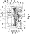
- Figure 4 shows a section through the connection box 7.
- the front extension part 29 of the connection box extension 8 has a greater height compared to the outer housing 2 than the rear extension part 30.
- the extension edge 28 of the connection box extension 8 thus has a bevel with a height falling from the drive side of the motor to the fan side on.
- a step 47 can be formed on the connection box cover 9 in a space-saving manner by providing the lower edge of the connection box cover 9 with a corresponding bevel.
- the step 47 comprises two plateau surfaces, each of which has an essentially constant height above the outer housing 2, and an end face which connects the plateau surfaces and runs essentially perpendicular to the motor axis 15.
- connection box cover 9 A cable, which is led out of a connection piece 12, 13 arranged on the end face, is protected at the exit point by parts of the connection box cover 9 through the step 47. Due to the inclination, the higher shaped wall in the front attachment part 29 forms a protection for larger electronics, for example terminal boards or connectors for Power connector, in the front, in Figure 4 left part of the junction box interior, while in the rear, in Figure 4 Right part space for the openings 27 for the cable entry is created with a total of minimal overall height of the connection box 7. In the rear part of the connection box interior there is also space for flat electronics, for example signal electronics for data communication.
- a printed circuit board 35 with the electronics of the converter is arranged in the connection box interior.
- power components 32 are applied in a row transversely to the motor axis.
- the power components 32 have a contact surface for cooling. These contact surfaces are placed on a support surface 33 which is machined particularly flat in the terminal box base 31.
- heat-conducting paste is applied between the support surface 33 and the power component 32.
- connection box 7 The lower part of the connection box 7 is made from a cast part with the outer housing 2, and the connection box bottom 31 is a region of the outer housing 2 which is cooled on its inside by an air flow in the air duct 34 driven by the fan 26.
- the entire surface of the outer housing, which extends tubularly around the motor shaft 15, which carries the fan 26, can thus be used for cooling.
- the power components 32 are therefore thermally well coupled to a large surface, which is also swept over by cooling air. Cooling fins can therefore be dispensed with.
- the circuit board 35 is fastened to a fastening frame 36 by lugs 40.
- the fastening frame 36 completely covers the circuit board 35 except for individual openings for plug connectors 38.
- the fastening frame 36 is screwed to the bottom of the lower part.
- the electronics are thus protected from inadvertent contact or damage towards the top, that is to say towards the opening of the connection box attachment 8.
- the circuit board 35 is encapsulated with a thermally conductive potting compound. This potting compound produces a thermal coupling of further electronic components of the printed circuit board 35 with further planar bearing surfaces in the base of the connection box.
- a protective film is inserted between the potting compound and the base and is perforated on the contact surfaces.
- the circuit board 35 has a downwardly directed connector 50 to which the windings of the motor unit are connected.
- the connection lines are passed through a connection channel 51 which connects the interior of the connection box with the interior of the stator housing 3.
- the connection channel 51 provides space for receiving the connector 50 and for receiving an additional intermediate circuit capacitor 51.
- This intermediate circuit capacitor 51 is smaller than the one above the mounting frame 36, not shown, but is arranged closer to the power components 32.
- Reinforcements 41 running transversely over the top are formed on the fastening frame 36.
- the contact pressure can be transferred to the circuit board and from there to the power components 32.
- the latter are therefore pressed against the support surface 33 and fixed. This results in good heat dissipation from the power components 32 via the outer housing 2.
- a rim 48 is formed on the fastening frame 36 and has tongues 37.
- Another printed circuit board (not shown) for signal electronics and the rectifier and the intermediate circuit capacitor of the converter can be inserted into the rim 48.
- the tongues 37 engage with the lugs 42 when the further circuit board is inserted, whereby the further circuit board is held.
- the further circuit board is electrically connected to the circuit board 35 via a suitable plug connector with the plug connectors 38.
- the further printed circuit board comprises means for connecting the power supply of the converter and means for connecting the data communication lines.
- the rectifier unit and the intermediate circuit capacitor are arranged on the further guide plate in the left-hand area and are protected by the raised front attachment part 29 of the connection box attachment 8 even when the connection box cover 9 is removed.
- Figure 5 shows a schematic view of a further connection box 60 according to the invention from above.
- a first plateau surface 61 and a second plateau surface 62 are separated by an arcuate end surface 68.
- the second plateau surface 62 is offset by an amount relative to the first plateau surface 61 and is therefore further away from the viewer.
- Plateau surface 61, 62 and face 68 form a step.
- the end face 68 is guided at the ends of the arcuate region parallel to the side surfaces 69, 70 of the connection box 60.
- openings 64, 65, 66, 67 for the cable feed-through into the interior of the connection box 60.
- the openings 64, 65, 66, 67 each have an opening direction which is symbolized by arrows.
- connection box 60 has a plane of symmetry 63, from which the openings 64, 65, 66, 67 each point away with their opening directions.
- the openings 64, 65, 66, 67 each offer the possibility of a cable feedthrough which is protected by the second plateau surface 62 and the height of the end face 68.
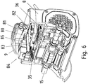
- FIG. 13 shows a sectional view of the converter motor from FIG Figure 1 with additional electronic options in the interior of the motor connection box.
- the printed circuit board 35 with the power electronics for motor control is attached.
- Another circuit board 80 is attached to the top of the mounting frame 36.
- At least one control electronics (not shown) for bus communication, a plug connector 83, a rectifier unit 84 of the converter and an intermediate circuit capacitor 85 are arranged on this printed circuit board 80.
- the rectifier unit 84 and the intermediate circuit capacitor 85 are designed for voltages of 400 V and more and for high currents of 1 A and more and therefore have an increased structural dimension.
- the additional interior space provided by the step in the connection box cover 9 is thus used.
- the plug connector 83 is designed to match a further plug connector, not shown, on the inside of the connection box cover 9. This further plug connector is plugged into the plug connector 83 by placing the connection box cover 9 on the connection box attachment 8. The connection line of the converter motor can thus be connected to the further plug connector via cable clamps.
- a third circuit board 81 is connected to the circuit board 80, preferably via a plug connection, the plug connectors of which are soldered to the respective circuit boards 80, 81.
- the third printed circuit board 81 is used to read out engine variables, in particular operational measured variables, which can be read out for diagnosis via a USB connection 82.
- an IR interface or another standard connector is provided.
- Figure 7 shows an oblique view of the converter motor from Figure 6 .
- the connection box cover 9 forms a bow-shaped step and differs from the connection box cover Figure 1 to 3 only through an additional opening 90, behind which a USB connection 82 for reading out operational measured variables is arranged.
- connection piece 91 for cables with a first diameter, alternatively a closure 93, a connection port 92 for cables with a second, smaller diameter, alternatively a closure 94, and a Connection piece 95 for data cables with an even more significantly smaller diameter, alternatively a closure 96.
- the arrangement of the connection pieces and closures is only an example, other combinations are also possible.
- connection openings allow cable routing that does not increase the interference contour of the converter motor, provided the cable is within the permitted bending radius. With the much more flexible data cables, however, one connection area is sufficient.
Landscapes
- Engineering & Computer Science (AREA)
- Power Engineering (AREA)
- Microelectronics & Electronic Packaging (AREA)
- Motor Or Generator Frames (AREA)
- Electric Propulsion And Braking For Vehicles (AREA)
Claims (15)
- Boîtier de connexion de moteur comprenant une partie inférieure (8) et une partie supérieure (9), un étage (47) étant formé dans la partie supérieure, l'étage comprenant deux surfaces de plateau et un côté frontal (20, 22, 43) reliant les surfaces de plateau et des ouvertures (27) pour des passages de câbles étant réalisées dans le côté frontal de l'étage,
caractérisé en ce
qu'une arête supérieure est réalisée au niveau de la partie inférieure (8), laquelle s'étend obliquement depuis une extrémité supérieure jusqu'à une extrémité inférieure, l'oblicité de l'arête supérieure de la partie inférieure (8) et l'étage (47) dans la partie supérieure (9) présentant une hauteur diminuant dans la même direction. - Boîtier de connexion de moteur selon la revendication précédente,
caractérisé en ce que
l'étage (47) présente un plan de symétrie et des ouvertures sont réalisées pour des passages de câbles des deux côtés du plan de symétrie. - Boîtier de connexion de moteur selon la revendication précédente,
caractérisé en ce que
les ouvertures (27) pour les passages de câbles sont orientées à l'écart du plan de symétrie, en particulier une première ouverture pour des passages de câbles étant réalisée dans une première région plane du côté frontal de l'étage, la prolongation mathématique de la première région plane coupant au moins deux surfaces latérales de la partie inférieure,
et/ou
une deuxième ouverture pour des passages de câbles étant réalisée dans une deuxième région plane du côté frontal de l'étage,
la prolongation mathématique de la première région plane coupant au moins deux surfaces latérales de la partie inférieure et la prolongation mathématique de la première région plane. - Boîtier de connexion de moteur selon l'une quelconque des revendications précédentes, caractérisé en ce que
une troisième ouverture (13, 23) pour des passages de câbles est réalisée dans une troisième région plane de la surface frontale de l'étage, la troisième ouverture présentant un plus petit diamètre que la deuxième ouverture et la première ouverture, en particulier la troisième région plane étant disposée entre la première région plane et la deuxième région plane. - Boîtier de connexion de moteur selon l'une quelconque des revendications 3 et 4,
caractérisé en ce que
la première région plane et la deuxième région plane forment un angle dont la pointe est orientée dans la direction de la hauteur décroissante de l'étage, en particulier l'angle inclus présentant un angle d'ouverture compris entre 60° et 100°,
en particulier l'angle inclus présentant un angle d'ouverture de 80°. - Boîtier de connexion de moteur selon l'une quelconque des revendications précédentes,
caractérisé en ce
qu'une électronique de convertisseur est prévue à l'intérieur du boîtier, en particulier l'électronique de convertisseur comprenant un composant de puissance (32) et une surface d'appui plane étant réalisée au fond de la partie inférieure, le composant de puissance étant placé sur la surface d'appui en vue de la dissipation de chaleur. - Boîtier de connexion de moteur selon la revendication précédente,
caractérisé en ce que
le composant de puissance est disposé sur une carte à circuits imprimés (35), la carte à circuits imprimés pressant le composant de puissance sur la surface d'appui. - Boîtier de connexion de moteur selon la revendication précédente,
caractérisé en ce
qu'un cadre de fixation (36) est prévu, sur lequel est fixée la carte à circuits imprimés et lequel recouvre la carte à circuits imprimés vers le haut, des ouvertures étant réalisées dans le cadre de fixation, à travers lesquelles s'étendent des pièces de connecteurs enfichables de la carte à circuits imprimés,
en particulier le cadre de fixation étant vissé à la partie inférieure et pressant la carte à circuits imprimés contre le fond de la partie inférieure ou le cadre de fixation présentant un bord, en particulier dans lequel sont réalisées des langues avec des ergots, une carte à circuits imprimés supplémentaire (80) étant encliquetée dans le bord, en particulier dans les langues avec ergots. - Boîtier de connexion de moteur selon la revendication précédente,
caractérisé en ce que
la carte à circuits imprimés supplémentaire (80) est connectée au connecteur enfichable de la première carte à circuits imprimés par le biais d'un connecteur enfichable adapté (83),
et/ou
un condensateur de circuit intermédiaire et/ou un module de redresseur sont disposés sur la carte à circuits imprimés supplémentaire dans une région qui est au moins en partie entourée par l'extrémité plus haute de la partie inférieure. - Boîtier de connexion de moteur selon l'une quelconque des revendications 6 à 9,
caractérisé en ce que
l'étage (47) forme dans la partie supérieure à l'intérieur du boîtier de connexion de moteur une région dans laquelle est ou sont disposés un condensateur de circuit intermédiaire (85) et/ou un module de redresseur (84) de l'électronique de convertisseur. - Boîtier de connexion de moteur selon l'une quelconque des revendications précédentes,
caractérisé en ce
qu'une partie tubulaire extérieure (2) est réalisée au niveau de la partie inférieure pour recevoir une unité de moteur, le fond de la partie inférieure formant une partie de la première partie tubulaire, en particulier une partie tubulaire intérieure (3) étant réalisée dans la partie tubulaire extérieure pour recevoir le stator d'une unité de moteur, l'axe de la partie tubulaire extérieure s'étendant parallèlement à l'axe de la partie tubulaire intérieure. - Boîtier de connexion de moteur selon la revendication précédente,
caractérisé en ce que
l'oblicité de l'arête supérieure de la partie inférieure présente une hauteur décroissante dans la direction de l'axe de la première partie tubulaire. - Boîtier de connexion de moteur selon l'une quelconque des revendications 11 et 12,
caractérisé en ce que
la partie inférieure et la partie tubulaire extérieure sont fabriquées en un corps moulé, en particulier la partie tubulaire extérieure et la partie tubulaire intérieure étant fabriquées en un corps moulé, des nervures s'étendant radialement reliant les deux parties. - Moteur-convertisseur, dans lequel sont prévues une partie tubulaire intérieure qui entoure le stator, et une partie tubulaire extérieure qui entoure la partie tubulaire intérieure, un ventilateur étant prévu dans la partie tubulaire extérieure, lequel déplace l'air le long du côté intérieur de la partie tubulaire extérieure,
caractérisé en ce
qu'au niveau du côté extérieur de la partie tubulaire extérieure est réalisé un boîtier de connexion de moteur selon au moins l'une quelconque des revendications précédentes. - Moteur-convertisseur selon la revendication précédente,
caractérisé en ce que
l'oblicité de l'arête supérieure de la partie inférieure présente une hauteur décroissante dans la direction de l'axe de la partie tubulaire extérieure,
la région de plus grande hauteur étant disposée au niveau du côté d'entraînement du moteur-convertisseur,
et/ou
une alimentation en puissance sans contact est prévue,
et/ou
l'arbre de moteur est disposé dans le plan de symétrie du boîtier de connexion de moteur.
Applications Claiming Priority (3)
| Application Number | Priority Date | Filing Date | Title |
|---|---|---|---|
| DE102007034915A DE102007034915B4 (de) | 2007-07-24 | 2007-07-24 | Motoranschlusskasten und Umrichtermotor |
| PCT/EP2008/005562 WO2009012883A2 (fr) | 2007-07-24 | 2008-07-08 | Boîtier de connexion de moteur et moteur à convertisseur |
| EP08784653.1A EP2174404B1 (fr) | 2007-07-24 | 2008-07-08 | Boitier de connexion de moteur et moteur a convertisseur |
Related Parent Applications (2)
| Application Number | Title | Priority Date | Filing Date |
|---|---|---|---|
| EP08784653.1A Division EP2174404B1 (fr) | 2007-07-24 | 2008-07-08 | Boitier de connexion de moteur et moteur a convertisseur |
| EP08784653.1A Division-Into EP2174404B1 (fr) | 2007-07-24 | 2008-07-08 | Boitier de connexion de moteur et moteur a convertisseur |
Publications (2)
| Publication Number | Publication Date |
|---|---|
| EP3386077A1 EP3386077A1 (fr) | 2018-10-10 |
| EP3386077B1 true EP3386077B1 (fr) | 2020-12-23 |
Family
ID=40155670
Family Applications (4)
| Application Number | Title | Priority Date | Filing Date |
|---|---|---|---|
| EP18000333.7A Active EP3386077B1 (fr) | 2007-07-24 | 2008-07-08 | Boîtier de connexion de moteur et moteur de convertisseur |
| EP18000504.3A Active EP3404807B1 (fr) | 2007-07-24 | 2008-07-08 | Boîtier de connexion de moteur et moteur de convertisseur |
| EP12004123.1A Active EP2521248B1 (fr) | 2007-07-24 | 2008-07-08 | Caisse de raccord moteur et moteur à convertisseur |
| EP08784653.1A Active EP2174404B1 (fr) | 2007-07-24 | 2008-07-08 | Boitier de connexion de moteur et moteur a convertisseur |
Family Applications After (3)
| Application Number | Title | Priority Date | Filing Date |
|---|---|---|---|
| EP18000504.3A Active EP3404807B1 (fr) | 2007-07-24 | 2008-07-08 | Boîtier de connexion de moteur et moteur de convertisseur |
| EP12004123.1A Active EP2521248B1 (fr) | 2007-07-24 | 2008-07-08 | Caisse de raccord moteur et moteur à convertisseur |
| EP08784653.1A Active EP2174404B1 (fr) | 2007-07-24 | 2008-07-08 | Boitier de connexion de moteur et moteur a convertisseur |
Country Status (10)
| Country | Link |
|---|---|
| US (1) | US8299662B2 (fr) |
| EP (4) | EP3386077B1 (fr) |
| CN (1) | CN101785169B (fr) |
| BR (3) | BR122019001374B1 (fr) |
| DE (1) | DE102007034915B4 (fr) |
| DK (1) | DK3404807T3 (fr) |
| ES (1) | ES2746376T3 (fr) |
| HU (1) | HUE046094T2 (fr) |
| PL (1) | PL3404807T3 (fr) |
| WO (1) | WO2009012883A2 (fr) |
Families Citing this family (21)
| Publication number | Priority date | Publication date | Assignee | Title |
|---|---|---|---|---|
| US8540493B2 (en) | 2003-12-08 | 2013-09-24 | Sta-Rite Industries, Llc | Pump control system and method |
| US8480373B2 (en) | 2004-08-26 | 2013-07-09 | Pentair Water Pool And Spa, Inc. | Filter loading |
| US8602745B2 (en) | 2004-08-26 | 2013-12-10 | Pentair Water Pool And Spa, Inc. | Anti-entrapment and anti-dead head function |
| US8469675B2 (en) | 2004-08-26 | 2013-06-25 | Pentair Water Pool And Spa, Inc. | Priming protection |
| US7845913B2 (en) | 2004-08-26 | 2010-12-07 | Pentair Water Pool And Spa, Inc. | Flow control |
| US8043070B2 (en) | 2004-08-26 | 2011-10-25 | Pentair Water Pool And Spa, Inc. | Speed control |
| US7874808B2 (en) | 2004-08-26 | 2011-01-25 | Pentair Water Pool And Spa, Inc. | Variable speed pumping system and method |
| US7686589B2 (en) | 2004-08-26 | 2010-03-30 | Pentair Water Pool And Spa, Inc. | Pumping system with power optimization |
| US8313306B2 (en) | 2008-10-06 | 2012-11-20 | Pentair Water Pool And Spa, Inc. | Method of operating a safety vacuum release system |
| US9556874B2 (en) | 2009-06-09 | 2017-01-31 | Pentair Flow Technologies, Llc | Method of controlling a pump and motor |
| JP4958988B2 (ja) * | 2010-03-30 | 2012-06-20 | 株式会社豊田自動織機 | 電動圧縮機 |
| EP2453560B1 (fr) | 2010-11-11 | 2022-11-02 | Grundfos Management a/s | Groupe motopompe |
| US8497611B2 (en) | 2011-04-22 | 2013-07-30 | Regal Beloit America, Inc. | Motor end frame |
| US9030066B2 (en) * | 2011-10-31 | 2015-05-12 | Regal Beloit America, Inc. | Electric motor with multiple power access |
| EP2626566B1 (fr) * | 2012-02-08 | 2021-07-28 | Grundfos Holding A/S | Moteur électrique |
| DE102014114837A1 (de) * | 2014-10-13 | 2016-04-14 | Bitzer Kühlmaschinenbau Gmbh | Kältemittelverdichter |
| US10284047B2 (en) | 2016-05-09 | 2019-05-07 | Bluffton Motor Works Llc | Electric motor for washdown, food processing, and chemical applications |
| CN107086727A (zh) * | 2017-06-13 | 2017-08-22 | 浙江佳雪微特电机集团有限责任公司 | 一种大功率永磁无刷水泵电机 |
| EP3817203B1 (fr) | 2019-10-29 | 2021-09-08 | Wilo Se | Fixation détachable d'un convertisseur de fréquence sur un moteur électrique |
| DE102021214770A1 (de) | 2021-12-21 | 2023-06-22 | Robert Bosch Gesellschaft mit beschränkter Haftung | E-Achsen-Modul eines elektrisch angetriebenen Fahrzeugs |
| DE102022001009B3 (de) | 2022-03-23 | 2023-05-04 | Sew-Eurodrive Gmbh & Co Kg | Antrieb, aufweisend einen Elektromotor, ein Gehäuseteil und ein Elektronikmodul |
Family Cites Families (29)
| Publication number | Priority date | Publication date | Assignee | Title |
|---|---|---|---|---|
| DE7342532U (de) * | 1974-03-14 | Bbc Ag | Spannungsumschaltbare, schlagwetter- oder explosionsgeschützte elektrische Maschine | |
| DE1284505B (de) * | 1962-02-22 | 1968-12-05 | Simon Hans | Anschlusskasten fuer elektrische Geraete |
| US4451750A (en) * | 1981-02-03 | 1984-05-29 | Elektro-Mechanik Gmbh | Protective arrangement for a plug-connected electric motor sealed against pressure, vapors and radiation |
| DE3105428C2 (de) * | 1981-02-14 | 1986-10-16 | Grundfos A/S, Bjerringbro | Naßläufermotor für eine Pumpe |
| JPH0657067U (ja) * | 1992-12-25 | 1994-08-05 | 株式会社東芝 | 回転電機 |
| JP3077490B2 (ja) * | 1993-12-28 | 2000-08-14 | 株式会社荏原製作所 | ポンプ組立体 |
| DE4435510C1 (de) * | 1994-10-04 | 1996-03-07 | Grundfos As | Frequenzumrichtergespeistes Pumpenaggregat |
| DE9415934U1 (de) * | 1994-10-04 | 1994-11-24 | Grundfos As | Pumpenaggregat |
| US5766026A (en) * | 1994-10-07 | 1998-06-16 | The Whitaker Corporation | Electrical connector assembly with sealed and spring biased electrical component |
| US5613844A (en) * | 1994-11-15 | 1997-03-25 | Walbro Corporation | Submersible electronic drive module |
| DE19704801C2 (de) * | 1997-02-08 | 1999-04-29 | Phoenix Contact Gmbh & Co | Netzbetriebener Elektromotor |
| DE19706188C2 (de) * | 1997-02-17 | 1999-05-06 | Kueppersbusch | Kabelanschlußvorrichtung |
| US5856717A (en) * | 1997-03-31 | 1999-01-05 | Reliance Electric Industrial Company | Enclosure for an electric motor |
| DE19817333C5 (de) * | 1998-04-18 | 2007-04-26 | Conti Temic Microelectronic Gmbh | Elektrische Antriebseinheit aus Elektromotor und Elektronikmodul |
| US6099325A (en) * | 1998-11-05 | 2000-08-08 | Ford Motor Company | Electronic control module for an electric motor |
| DE19956429A1 (de) * | 1999-11-24 | 2001-06-13 | Grundfos As | Elektromotor für insbesondere eine Kreiselpumpe |
| DE10006320A1 (de) * | 2000-02-12 | 2001-08-23 | Daimler Chrysler Ag | Elektrische Antriebseinheit aus Elektromotor und Elektronikmodul |
| US6664682B2 (en) * | 2001-02-28 | 2003-12-16 | Reliance Electric Technologies, Llc | Method and apparatus for securing a conduit box to a motor and motor incorporating same |
| DE10302791B4 (de) * | 2002-01-30 | 2016-03-17 | Denso Corporation | Elektrokompressor |
| DE10339340B4 (de) * | 2003-08-25 | 2020-02-20 | Sew-Eurodrive Gmbh & Co Kg | Vorrichtung zur berührungslosen Energieübertragung |
| ATE402514T1 (de) * | 2004-04-01 | 2008-08-15 | Sew Eurodrive Gmbh & Co | Elektromotor und baureihe von elektromotoren |
| DE102004036281A1 (de) * | 2004-07-27 | 2005-11-10 | Siemens Ag | Elektrischer Kompaktantrieb |
| DE102004039682A1 (de) * | 2004-08-16 | 2006-03-30 | Siemens Ag | Anschlussvorrichtung für eine elektrische Maschine |
| DE102004048461A1 (de) * | 2004-10-05 | 2006-04-27 | Siemens Ag | Gehäuse für eine elektrische Maschine |
| CN2753047Y (zh) * | 2004-11-17 | 2006-01-18 | 佳木斯防爆电机研究所 | 起重及冶金用绕线转子三相异步电动机 |
| DE102005022367B4 (de) * | 2005-05-10 | 2021-05-20 | Sew-Eurodrive Gmbh & Co Kg | Berührungslos versorgter Verbraucher und System |
| DE102005041136B4 (de) * | 2005-08-30 | 2023-11-02 | Sew-Eurodrive Gmbh & Co Kg | Umrichtermotor und Verfahren |
| JP5221935B2 (ja) * | 2007-11-06 | 2013-06-26 | 三菱重工業株式会社 | インバータ一体型電動圧縮機 |
| JP4909961B2 (ja) * | 2008-09-02 | 2012-04-04 | 日立オートモティブシステムズ株式会社 | 電動パワーステアリング用制御装置 |
-
2007
- 2007-07-24 DE DE102007034915A patent/DE102007034915B4/de active Active
-
2008
- 2008-07-08 EP EP18000333.7A patent/EP3386077B1/fr active Active
- 2008-07-08 EP EP18000504.3A patent/EP3404807B1/fr active Active
- 2008-07-08 PL PL18000504T patent/PL3404807T3/pl unknown
- 2008-07-08 WO PCT/EP2008/005562 patent/WO2009012883A2/fr active Application Filing
- 2008-07-08 EP EP12004123.1A patent/EP2521248B1/fr active Active
- 2008-07-08 ES ES18000504T patent/ES2746376T3/es active Active
- 2008-07-08 US US12/670,475 patent/US8299662B2/en active Active
- 2008-07-08 HU HUE18000504A patent/HUE046094T2/hu unknown
- 2008-07-08 CN CN2008801001076A patent/CN101785169B/zh active Active
- 2008-07-08 EP EP08784653.1A patent/EP2174404B1/fr active Active
- 2008-07-08 BR BR122019001374-8A patent/BR122019001374B1/pt active IP Right Grant
- 2008-07-08 BR BR122019001378-0A patent/BR122019001378B1/pt active IP Right Grant
- 2008-07-08 DK DK18000504.3T patent/DK3404807T3/da active
- 2008-07-08 BR BRPI0814128A patent/BRPI0814128A2/pt not_active Application Discontinuation
Non-Patent Citations (1)
| Title |
|---|
| None * |
Also Published As
| Publication number | Publication date |
|---|---|
| DE102007034915A1 (de) | 2009-02-05 |
| DE102007034915B4 (de) | 2011-01-05 |
| US8299662B2 (en) | 2012-10-30 |
| US20100237722A1 (en) | 2010-09-23 |
| DK3404807T3 (da) | 2019-09-23 |
| EP2174404A2 (fr) | 2010-04-14 |
| CN101785169B (zh) | 2012-10-10 |
| ES2746376T3 (es) | 2020-03-05 |
| HUE046094T2 (hu) | 2020-01-28 |
| WO2009012883A3 (fr) | 2009-07-23 |
| EP3404807B1 (fr) | 2019-07-03 |
| EP2521248A3 (fr) | 2018-01-24 |
| EP3386077A1 (fr) | 2018-10-10 |
| CN101785169A (zh) | 2010-07-21 |
| EP2521248B1 (fr) | 2019-02-27 |
| EP3404807A1 (fr) | 2018-11-21 |
| BRPI0814128A2 (pt) | 2015-10-06 |
| PL3404807T3 (pl) | 2019-11-29 |
| EP2174404B1 (fr) | 2020-01-22 |
| WO2009012883A2 (fr) | 2009-01-29 |
| EP2521248A2 (fr) | 2012-11-07 |
| BR122019001378B1 (pt) | 2020-11-17 |
| BR122019001374B1 (pt) | 2020-09-29 |
Similar Documents
| Publication | Publication Date | Title |
|---|---|---|
| EP3386077B1 (fr) | Boîtier de connexion de moteur et moteur de convertisseur | |
| EP2639940B1 (fr) | Moteur électrique | |
| EP0958646B1 (fr) | Moteur electrique a convertisseur de frequence monte en amont | |
| EP1848260B1 (fr) | Onduleur | |
| EP2607707B2 (fr) | Moteur électrique | |
| DE102007034913B4 (de) | Lüfterhaube für einen Umrichtermotor, Umrichtermotor und Baureihe von Umrichtermotoren | |
| EP1237260B1 (fr) | Moteur à convertisseur et gamme de système d'entraînement | |
| DE102013100607A1 (de) | Wechselrichter mit zweiteiligem Gehäuse | |
| EP2750266B1 (fr) | Groupe motopompe | |
| EP2449671B1 (fr) | Moteur électrique et installation équipée de moteurs électriques | |
| DE102010047762A1 (de) | Umrichtermotor, Umrichter und Kühlkörper | |
| WO2014102174A2 (fr) | Groupe motopompe | |
| EP2073616A2 (fr) | Unité d'appareil dotée de canaux d'air froid | |
| EP2639944B1 (fr) | Moteur électrique | |
| DE10153173A1 (de) | Elektrischer Antrieb, insbesondere Scheibenwischer-Antrieb | |
| DE102012001389B4 (de) | Getriebe mit einem zentralen Gehäuseteil | |
| DE202008007238U1 (de) | Beleuchtungseinrichtung | |
| DE102022001009B3 (de) | Antrieb, aufweisend einen Elektromotor, ein Gehäuseteil und ein Elektronikmodul | |
| DE102012001388B4 (de) | Getriebe mit einem zentralen Gehäuseteil | |
| DE102018106803A1 (de) | Elektronikgehäuseanordnung und Verfahren zu deren Bildung |
Legal Events
| Date | Code | Title | Description |
|---|---|---|---|
| PUAI | Public reference made under article 153(3) epc to a published international application that has entered the european phase |
Free format text: ORIGINAL CODE: 0009012 |
|
| STAA | Information on the status of an ep patent application or granted ep patent |
Free format text: STATUS: REQUEST FOR EXAMINATION WAS MADE |
|
| STAA | Information on the status of an ep patent application or granted ep patent |
Free format text: STATUS: EXAMINATION IS IN PROGRESS |
|
| 17P | Request for examination filed |
Effective date: 20180420 |
|
| AC | Divisional application: reference to earlier application |
Ref document number: 2174404 Country of ref document: EP Kind code of ref document: P |
|
| AK | Designated contracting states |
Kind code of ref document: A1 Designated state(s): AT BE BG CH CY CZ DE DK EE ES FI FR GB GR HR HU IE IS IT LI LT LU LV MC MT NL NO PL PT RO SE SI SK TR |
|
| 17Q | First examination report despatched |
Effective date: 20181004 |
|
| R17C | First examination report despatched (corrected) |
Effective date: 20181004 |
|
| RBV | Designated contracting states (corrected) |
Designated state(s): AT BE BG CH CY CZ DE DK EE ES FI FR GB GR HR HU IE IS IT LI LT LU LV MC MT NL NO PL PT RO SE SI SK TR |
|
| GRAP | Despatch of communication of intention to grant a patent |
Free format text: ORIGINAL CODE: EPIDOSNIGR1 |
|
| STAA | Information on the status of an ep patent application or granted ep patent |
Free format text: STATUS: GRANT OF PATENT IS INTENDED |
|
| RIC1 | Information provided on ipc code assigned before grant |
Ipc: H02K 11/33 20160101ALI20200619BHEP Ipc: H02K 5/22 20060101AFI20200619BHEP Ipc: H02K 9/14 20060101ALI20200619BHEP Ipc: H02K 5/20 20060101ALN20200619BHEP |
|
| RIC1 | Information provided on ipc code assigned before grant |
Ipc: H02K 5/20 20060101ALN20200706BHEP Ipc: H02K 11/33 20160101ALI20200706BHEP Ipc: H02K 9/14 20060101ALI20200706BHEP Ipc: H02K 5/22 20060101AFI20200706BHEP |
|
| INTG | Intention to grant announced |
Effective date: 20200723 |
|
| GRAS | Grant fee paid |
Free format text: ORIGINAL CODE: EPIDOSNIGR3 |
|
| GRAA | (expected) grant |
Free format text: ORIGINAL CODE: 0009210 |
|
| STAA | Information on the status of an ep patent application or granted ep patent |
Free format text: STATUS: THE PATENT HAS BEEN GRANTED |
|
| AC | Divisional application: reference to earlier application |
Ref document number: 2174404 Country of ref document: EP Kind code of ref document: P |
|
| AK | Designated contracting states |
Kind code of ref document: B1 Designated state(s): AT BE BG CH CY CZ DE DK EE ES FI FR GB GR HR HU IE IS IT LI LT LU LV MC MT NL NO PL PT RO SE SI SK TR |
|
| REG | Reference to a national code |
Ref country code: GB Ref legal event code: FG4D Free format text: NOT ENGLISH |
|
| REG | Reference to a national code |
Ref country code: DE Ref legal event code: R096 Ref document number: 502008017176 Country of ref document: DE |
|
| REG | Reference to a national code |
Ref country code: AT Ref legal event code: REF Ref document number: 1348671 Country of ref document: AT Kind code of ref document: T Effective date: 20210115 |
|
| REG | Reference to a national code |
Ref country code: IE Ref legal event code: FG4D Free format text: LANGUAGE OF EP DOCUMENT: GERMAN |
|
| PG25 | Lapsed in a contracting state [announced via postgrant information from national office to epo] |
Ref country code: GR Free format text: LAPSE BECAUSE OF FAILURE TO SUBMIT A TRANSLATION OF THE DESCRIPTION OR TO PAY THE FEE WITHIN THE PRESCRIBED TIME-LIMIT Effective date: 20210324 Ref country code: NO Free format text: LAPSE BECAUSE OF FAILURE TO SUBMIT A TRANSLATION OF THE DESCRIPTION OR TO PAY THE FEE WITHIN THE PRESCRIBED TIME-LIMIT Effective date: 20210323 Ref country code: FI Free format text: LAPSE BECAUSE OF FAILURE TO SUBMIT A TRANSLATION OF THE DESCRIPTION OR TO PAY THE FEE WITHIN THE PRESCRIBED TIME-LIMIT Effective date: 20201223 |
|
| REG | Reference to a national code |
Ref country code: NL Ref legal event code: MP Effective date: 20201223 |
|
| PG25 | Lapsed in a contracting state [announced via postgrant information from national office to epo] |
Ref country code: SE Free format text: LAPSE BECAUSE OF FAILURE TO SUBMIT A TRANSLATION OF THE DESCRIPTION OR TO PAY THE FEE WITHIN THE PRESCRIBED TIME-LIMIT Effective date: 20201223 Ref country code: LV Free format text: LAPSE BECAUSE OF FAILURE TO SUBMIT A TRANSLATION OF THE DESCRIPTION OR TO PAY THE FEE WITHIN THE PRESCRIBED TIME-LIMIT Effective date: 20201223 Ref country code: BG Free format text: LAPSE BECAUSE OF FAILURE TO SUBMIT A TRANSLATION OF THE DESCRIPTION OR TO PAY THE FEE WITHIN THE PRESCRIBED TIME-LIMIT Effective date: 20210323 |
|
| PG25 | Lapsed in a contracting state [announced via postgrant information from national office to epo] |
Ref country code: NL Free format text: LAPSE BECAUSE OF FAILURE TO SUBMIT A TRANSLATION OF THE DESCRIPTION OR TO PAY THE FEE WITHIN THE PRESCRIBED TIME-LIMIT Effective date: 20201223 Ref country code: HR Free format text: LAPSE BECAUSE OF FAILURE TO SUBMIT A TRANSLATION OF THE DESCRIPTION OR TO PAY THE FEE WITHIN THE PRESCRIBED TIME-LIMIT Effective date: 20201223 |
|
| REG | Reference to a national code |
Ref country code: LT Ref legal event code: MG9D |
|
| PG25 | Lapsed in a contracting state [announced via postgrant information from national office to epo] |
Ref country code: CZ Free format text: LAPSE BECAUSE OF FAILURE TO SUBMIT A TRANSLATION OF THE DESCRIPTION OR TO PAY THE FEE WITHIN THE PRESCRIBED TIME-LIMIT Effective date: 20201223 Ref country code: EE Free format text: LAPSE BECAUSE OF FAILURE TO SUBMIT A TRANSLATION OF THE DESCRIPTION OR TO PAY THE FEE WITHIN THE PRESCRIBED TIME-LIMIT Effective date: 20201223 Ref country code: LT Free format text: LAPSE BECAUSE OF FAILURE TO SUBMIT A TRANSLATION OF THE DESCRIPTION OR TO PAY THE FEE WITHIN THE PRESCRIBED TIME-LIMIT Effective date: 20201223 Ref country code: SK Free format text: LAPSE BECAUSE OF FAILURE TO SUBMIT A TRANSLATION OF THE DESCRIPTION OR TO PAY THE FEE WITHIN THE PRESCRIBED TIME-LIMIT Effective date: 20201223 Ref country code: PT Free format text: LAPSE BECAUSE OF FAILURE TO SUBMIT A TRANSLATION OF THE DESCRIPTION OR TO PAY THE FEE WITHIN THE PRESCRIBED TIME-LIMIT Effective date: 20210423 Ref country code: RO Free format text: LAPSE BECAUSE OF FAILURE TO SUBMIT A TRANSLATION OF THE DESCRIPTION OR TO PAY THE FEE WITHIN THE PRESCRIBED TIME-LIMIT Effective date: 20201223 |
|
| PG25 | Lapsed in a contracting state [announced via postgrant information from national office to epo] |
Ref country code: PL Free format text: LAPSE BECAUSE OF FAILURE TO SUBMIT A TRANSLATION OF THE DESCRIPTION OR TO PAY THE FEE WITHIN THE PRESCRIBED TIME-LIMIT Effective date: 20201223 |
|
| REG | Reference to a national code |
Ref country code: DE Ref legal event code: R097 Ref document number: 502008017176 Country of ref document: DE |
|
| PG25 | Lapsed in a contracting state [announced via postgrant information from national office to epo] |
Ref country code: IS Free format text: LAPSE BECAUSE OF FAILURE TO SUBMIT A TRANSLATION OF THE DESCRIPTION OR TO PAY THE FEE WITHIN THE PRESCRIBED TIME-LIMIT Effective date: 20210423 |
|
| PLBE | No opposition filed within time limit |
Free format text: ORIGINAL CODE: 0009261 |
|
| STAA | Information on the status of an ep patent application or granted ep patent |
Free format text: STATUS: NO OPPOSITION FILED WITHIN TIME LIMIT |
|
| PG25 | Lapsed in a contracting state [announced via postgrant information from national office to epo] |
Ref country code: DK Free format text: LAPSE BECAUSE OF FAILURE TO SUBMIT A TRANSLATION OF THE DESCRIPTION OR TO PAY THE FEE WITHIN THE PRESCRIBED TIME-LIMIT Effective date: 20201223 |
|
| 26N | No opposition filed |
Effective date: 20210924 |
|
| PG25 | Lapsed in a contracting state [announced via postgrant information from national office to epo] |
Ref country code: ES Free format text: LAPSE BECAUSE OF FAILURE TO SUBMIT A TRANSLATION OF THE DESCRIPTION OR TO PAY THE FEE WITHIN THE PRESCRIBED TIME-LIMIT Effective date: 20201223 |
|
| PG25 | Lapsed in a contracting state [announced via postgrant information from national office to epo] |
Ref country code: SI Free format text: LAPSE BECAUSE OF FAILURE TO SUBMIT A TRANSLATION OF THE DESCRIPTION OR TO PAY THE FEE WITHIN THE PRESCRIBED TIME-LIMIT Effective date: 20201223 |
|
| REG | Reference to a national code |
Ref country code: CH Ref legal event code: PL |
|
| GBPC | Gb: european patent ceased through non-payment of renewal fee |
Effective date: 20210708 |
|
| PG25 | Lapsed in a contracting state [announced via postgrant information from national office to epo] |
Ref country code: MC Free format text: LAPSE BECAUSE OF FAILURE TO SUBMIT A TRANSLATION OF THE DESCRIPTION OR TO PAY THE FEE WITHIN THE PRESCRIBED TIME-LIMIT Effective date: 20201223 |
|
| REG | Reference to a national code |
Ref country code: BE Ref legal event code: MM Effective date: 20210731 |
|
| PG25 | Lapsed in a contracting state [announced via postgrant information from national office to epo] |
Ref country code: LI Free format text: LAPSE BECAUSE OF NON-PAYMENT OF DUE FEES Effective date: 20210731 Ref country code: GB Free format text: LAPSE BECAUSE OF NON-PAYMENT OF DUE FEES Effective date: 20210708 Ref country code: CH Free format text: LAPSE BECAUSE OF NON-PAYMENT OF DUE FEES Effective date: 20210731 |
|
| PG25 | Lapsed in a contracting state [announced via postgrant information from national office to epo] |
Ref country code: IS Free format text: LAPSE BECAUSE OF FAILURE TO SUBMIT A TRANSLATION OF THE DESCRIPTION OR TO PAY THE FEE WITHIN THE PRESCRIBED TIME-LIMIT Effective date: 20210423 Ref country code: LU Free format text: LAPSE BECAUSE OF NON-PAYMENT OF DUE FEES Effective date: 20210708 |
|
| PG25 | Lapsed in a contracting state [announced via postgrant information from national office to epo] |
Ref country code: IE Free format text: LAPSE BECAUSE OF NON-PAYMENT OF DUE FEES Effective date: 20210708 Ref country code: BE Free format text: LAPSE BECAUSE OF NON-PAYMENT OF DUE FEES Effective date: 20210731 |
|
| PG25 | Lapsed in a contracting state [announced via postgrant information from national office to epo] |
Ref country code: CY Free format text: LAPSE BECAUSE OF FAILURE TO SUBMIT A TRANSLATION OF THE DESCRIPTION OR TO PAY THE FEE WITHIN THE PRESCRIBED TIME-LIMIT Effective date: 20201223 |
|
| PG25 | Lapsed in a contracting state [announced via postgrant information from national office to epo] |
Ref country code: HU Free format text: LAPSE BECAUSE OF FAILURE TO SUBMIT A TRANSLATION OF THE DESCRIPTION OR TO PAY THE FEE WITHIN THE PRESCRIBED TIME-LIMIT; INVALID AB INITIO Effective date: 20080708 |
|
| PGFP | Annual fee paid to national office [announced via postgrant information from national office to epo] |
Ref country code: IT Payment date: 20230612 Year of fee payment: 16 |
|
| PGFP | Annual fee paid to national office [announced via postgrant information from national office to epo] |
Ref country code: AT Payment date: 20230711 Year of fee payment: 16 |
|
| PGFP | Annual fee paid to national office [announced via postgrant information from national office to epo] |
Ref country code: DE Payment date: 20230731 Year of fee payment: 16 |
|
| PGFP | Annual fee paid to national office [announced via postgrant information from national office to epo] |
Ref country code: FR Payment date: 20240611 Year of fee payment: 17 |