EP3385506A1 - Dichtungsanordnung für eine gasturbine - Google Patents
Dichtungsanordnung für eine gasturbine Download PDFInfo
- Publication number
- EP3385506A1 EP3385506A1 EP17165617.6A EP17165617A EP3385506A1 EP 3385506 A1 EP3385506 A1 EP 3385506A1 EP 17165617 A EP17165617 A EP 17165617A EP 3385506 A1 EP3385506 A1 EP 3385506A1
- Authority
- EP
- European Patent Office
- Prior art keywords
- sealing
- component
- flange portion
- gas turbine
- seal
- Prior art date
- Legal status (The legal status is an assumption and is not a legal conclusion. Google has not performed a legal analysis and makes no representation as to the accuracy of the status listed.)
- Granted
Links
Images



Classifications
-
- F—MECHANICAL ENGINEERING; LIGHTING; HEATING; WEAPONS; BLASTING
- F01—MACHINES OR ENGINES IN GENERAL; ENGINE PLANTS IN GENERAL; STEAM ENGINES
- F01D—NON-POSITIVE DISPLACEMENT MACHINES OR ENGINES, e.g. STEAM TURBINES
- F01D25/00—Component parts, details, or accessories, not provided for in, or of interest apart from, other groups
- F01D25/24—Casings; Casing parts, e.g. diaphragms, casing fastenings
- F01D25/243—Flange connections; Bolting arrangements
-
- F—MECHANICAL ENGINEERING; LIGHTING; HEATING; WEAPONS; BLASTING
- F01—MACHINES OR ENGINES IN GENERAL; ENGINE PLANTS IN GENERAL; STEAM ENGINES
- F01D—NON-POSITIVE DISPLACEMENT MACHINES OR ENGINES, e.g. STEAM TURBINES
- F01D11/00—Preventing or minimising internal leakage of working-fluid, e.g. between stages
- F01D11/003—Preventing or minimising internal leakage of working-fluid, e.g. between stages by packing rings; Mechanical seals
-
- F—MECHANICAL ENGINEERING; LIGHTING; HEATING; WEAPONS; BLASTING
- F01—MACHINES OR ENGINES IN GENERAL; ENGINE PLANTS IN GENERAL; STEAM ENGINES
- F01D—NON-POSITIVE DISPLACEMENT MACHINES OR ENGINES, e.g. STEAM TURBINES
- F01D11/00—Preventing or minimising internal leakage of working-fluid, e.g. between stages
- F01D11/005—Sealing means between non relatively rotating elements
-
- F—MECHANICAL ENGINEERING; LIGHTING; HEATING; WEAPONS; BLASTING
- F01—MACHINES OR ENGINES IN GENERAL; ENGINE PLANTS IN GENERAL; STEAM ENGINES
- F01D—NON-POSITIVE DISPLACEMENT MACHINES OR ENGINES, e.g. STEAM TURBINES
- F01D25/00—Component parts, details, or accessories, not provided for in, or of interest apart from, other groups
- F01D25/28—Supporting or mounting arrangements, e.g. for turbine casing
-
- F—MECHANICAL ENGINEERING; LIGHTING; HEATING; WEAPONS; BLASTING
- F01—MACHINES OR ENGINES IN GENERAL; ENGINE PLANTS IN GENERAL; STEAM ENGINES
- F01D—NON-POSITIVE DISPLACEMENT MACHINES OR ENGINES, e.g. STEAM TURBINES
- F01D9/00—Stators
- F01D9/06—Fluid supply conduits to nozzles or the like
- F01D9/065—Fluid supply or removal conduits traversing the working fluid flow, e.g. for lubrication-, cooling-, or sealing fluids
-
- F—MECHANICAL ENGINEERING; LIGHTING; HEATING; WEAPONS; BLASTING
- F01—MACHINES OR ENGINES IN GENERAL; ENGINE PLANTS IN GENERAL; STEAM ENGINES
- F01D—NON-POSITIVE DISPLACEMENT MACHINES OR ENGINES, e.g. STEAM TURBINES
- F01D11/00—Preventing or minimising internal leakage of working-fluid, e.g. between stages
- F01D11/001—Preventing or minimising internal leakage of working-fluid, e.g. between stages for sealing space between stator blade and rotor
-
- F—MECHANICAL ENGINEERING; LIGHTING; HEATING; WEAPONS; BLASTING
- F01—MACHINES OR ENGINES IN GENERAL; ENGINE PLANTS IN GENERAL; STEAM ENGINES
- F01D—NON-POSITIVE DISPLACEMENT MACHINES OR ENGINES, e.g. STEAM TURBINES
- F01D25/00—Component parts, details, or accessories, not provided for in, or of interest apart from, other groups
- F01D25/24—Casings; Casing parts, e.g. diaphragms, casing fastenings
- F01D25/246—Fastening of diaphragms or stator-rings
-
- F—MECHANICAL ENGINEERING; LIGHTING; HEATING; WEAPONS; BLASTING
- F02—COMBUSTION ENGINES; HOT-GAS OR COMBUSTION-PRODUCT ENGINE PLANTS
- F02C—GAS-TURBINE PLANTS; AIR INTAKES FOR JET-PROPULSION PLANTS; CONTROLLING FUEL SUPPLY IN AIR-BREATHING JET-PROPULSION PLANTS
- F02C7/00—Features, components parts, details or accessories, not provided for in, or of interest apart form groups F02C1/00 - F02C6/00; Air intakes for jet-propulsion plants
- F02C7/28—Arrangement of seals
-
- F—MECHANICAL ENGINEERING; LIGHTING; HEATING; WEAPONS; BLASTING
- F05—INDEXING SCHEMES RELATING TO ENGINES OR PUMPS IN VARIOUS SUBCLASSES OF CLASSES F01-F04
- F05D—INDEXING SCHEME FOR ASPECTS RELATING TO NON-POSITIVE-DISPLACEMENT MACHINES OR ENGINES, GAS-TURBINES OR JET-PROPULSION PLANTS
- F05D2220/00—Application
- F05D2220/30—Application in turbines
- F05D2220/32—Application in turbines in gas turbines
-
- F—MECHANICAL ENGINEERING; LIGHTING; HEATING; WEAPONS; BLASTING
- F05—INDEXING SCHEMES RELATING TO ENGINES OR PUMPS IN VARIOUS SUBCLASSES OF CLASSES F01-F04
- F05D—INDEXING SCHEME FOR ASPECTS RELATING TO NON-POSITIVE-DISPLACEMENT MACHINES OR ENGINES, GAS-TURBINES OR JET-PROPULSION PLANTS
- F05D2240/00—Components
- F05D2240/55—Seals
-
- F—MECHANICAL ENGINEERING; LIGHTING; HEATING; WEAPONS; BLASTING
- F05—INDEXING SCHEMES RELATING TO ENGINES OR PUMPS IN VARIOUS SUBCLASSES OF CLASSES F01-F04
- F05D—INDEXING SCHEME FOR ASPECTS RELATING TO NON-POSITIVE-DISPLACEMENT MACHINES OR ENGINES, GAS-TURBINES OR JET-PROPULSION PLANTS
- F05D2240/00—Components
- F05D2240/55—Seals
- F05D2240/57—Leaf seals
-
- F—MECHANICAL ENGINEERING; LIGHTING; HEATING; WEAPONS; BLASTING
- F05—INDEXING SCHEMES RELATING TO ENGINES OR PUMPS IN VARIOUS SUBCLASSES OF CLASSES F01-F04
- F05D—INDEXING SCHEME FOR ASPECTS RELATING TO NON-POSITIVE-DISPLACEMENT MACHINES OR ENGINES, GAS-TURBINES OR JET-PROPULSION PLANTS
- F05D2250/00—Geometry
- F05D2250/70—Shape
- F05D2250/71—Shape curved
-
- F—MECHANICAL ENGINEERING; LIGHTING; HEATING; WEAPONS; BLASTING
- F05—INDEXING SCHEMES RELATING TO ENGINES OR PUMPS IN VARIOUS SUBCLASSES OF CLASSES F01-F04
- F05D—INDEXING SCHEME FOR ASPECTS RELATING TO NON-POSITIVE-DISPLACEMENT MACHINES OR ENGINES, GAS-TURBINES OR JET-PROPULSION PLANTS
- F05D2260/00—Function
- F05D2260/30—Retaining components in desired mutual position
-
- F—MECHANICAL ENGINEERING; LIGHTING; HEATING; WEAPONS; BLASTING
- F16—ENGINEERING ELEMENTS AND UNITS; GENERAL MEASURES FOR PRODUCING AND MAINTAINING EFFECTIVE FUNCTIONING OF MACHINES OR INSTALLATIONS; THERMAL INSULATION IN GENERAL
- F16J—PISTONS; CYLINDERS; SEALINGS
- F16J15/00—Sealings
-
- F—MECHANICAL ENGINEERING; LIGHTING; HEATING; WEAPONS; BLASTING
- F16—ENGINEERING ELEMENTS AND UNITS; GENERAL MEASURES FOR PRODUCING AND MAINTAINING EFFECTIVE FUNCTIONING OF MACHINES OR INSTALLATIONS; THERMAL INSULATION IN GENERAL
- F16J—PISTONS; CYLINDERS; SEALINGS
- F16J15/00—Sealings
- F16J15/02—Sealings between relatively-stationary surfaces
-
- F—MECHANICAL ENGINEERING; LIGHTING; HEATING; WEAPONS; BLASTING
- F16—ENGINEERING ELEMENTS AND UNITS; GENERAL MEASURES FOR PRODUCING AND MAINTAINING EFFECTIVE FUNCTIONING OF MACHINES OR INSTALLATIONS; THERMAL INSULATION IN GENERAL
- F16J—PISTONS; CYLINDERS; SEALINGS
- F16J15/00—Sealings
- F16J15/02—Sealings between relatively-stationary surfaces
- F16J15/06—Sealings between relatively-stationary surfaces with solid packing compressed between sealing surfaces
- F16J15/08—Sealings between relatively-stationary surfaces with solid packing compressed between sealing surfaces with exclusively metal packing
- F16J15/0887—Sealings between relatively-stationary surfaces with solid packing compressed between sealing surfaces with exclusively metal packing the sealing effect being obtained by elastic deformation of the packing
-
- F—MECHANICAL ENGINEERING; LIGHTING; HEATING; WEAPONS; BLASTING
- F16—ENGINEERING ELEMENTS AND UNITS; GENERAL MEASURES FOR PRODUCING AND MAINTAINING EFFECTIVE FUNCTIONING OF MACHINES OR INSTALLATIONS; THERMAL INSULATION IN GENERAL
- F16J—PISTONS; CYLINDERS; SEALINGS
- F16J15/00—Sealings
- F16J15/16—Sealings between relatively-moving surfaces
- F16J15/32—Sealings between relatively-moving surfaces with elastic sealings, e.g. O-rings
- F16J15/3284—Sealings between relatively-moving surfaces with elastic sealings, e.g. O-rings characterised by their structure; Selection of materials
-
- F—MECHANICAL ENGINEERING; LIGHTING; HEATING; WEAPONS; BLASTING
- F16—ENGINEERING ELEMENTS AND UNITS; GENERAL MEASURES FOR PRODUCING AND MAINTAINING EFFECTIVE FUNCTIONING OF MACHINES OR INSTALLATIONS; THERMAL INSULATION IN GENERAL
- F16J—PISTONS; CYLINDERS; SEALINGS
- F16J15/00—Sealings
- F16J15/16—Sealings between relatively-moving surfaces
- F16J15/32—Sealings between relatively-moving surfaces with elastic sealings, e.g. O-rings
- F16J15/3284—Sealings between relatively-moving surfaces with elastic sealings, e.g. O-rings characterised by their structure; Selection of materials
- F16J15/3292—Lamellar structures
-
- Y—GENERAL TAGGING OF NEW TECHNOLOGICAL DEVELOPMENTS; GENERAL TAGGING OF CROSS-SECTIONAL TECHNOLOGIES SPANNING OVER SEVERAL SECTIONS OF THE IPC; TECHNICAL SUBJECTS COVERED BY FORMER USPC CROSS-REFERENCE ART COLLECTIONS [XRACs] AND DIGESTS
- Y02—TECHNOLOGIES OR APPLICATIONS FOR MITIGATION OR ADAPTATION AGAINST CLIMATE CHANGE
- Y02T—CLIMATE CHANGE MITIGATION TECHNOLOGIES RELATED TO TRANSPORTATION
- Y02T50/00—Aeronautics or air transport
- Y02T50/60—Efficient propulsion technologies, e.g. for aircraft
Definitions
- the present invention relates to a sealing arrangement for a gas turbine, in particular an aircraft gas turbine, comprising: a first component having a first flange portion and a second component having a second flange portion, wherein the first component and the second component in the region of the first flange portion and the second flange portion by means of a Screw connection are releasably coupled together, wherein between the first component, in particular a rounding portion and the second component, in particular the second flange portion, a variable distance is provided, which is at least partially sealed by at least one sealing element.
- sealing plates which are pressed by a present in the gas turbine pressure difference at a sealing point against corresponding sealing surfaces.
- a distance between the sealing surfaces is usually quite large, in order to be able to absorb the thermo-mechanical deformations with simultaneous sealing action.
- the distance between the sealing surfaces is greater than a maximum expected displacement of the components relative to each other due to the thermal influences. Accordingly, the sealing surfaces against which the sealing plates abut relatively large must be selected in order to achieve the desired seal in each (B e-driven) state of the gas turbine.
- the object of the invention is to provide an improved sealing arrangement in which a seal can be reliably provided even with large displacements.
- the sealing element has a first seal portion abutting on the first component, in particular on the rounding portion, and a second seal portion bearing against the second component, in particular on the second flange portion, wherein the first seal portion and the second seal are connected to each other and are arranged inclined to each other.
- sealing portions By an inclined arrangement of the two sealing portions can be dispensed with a full surface contact with sealing surfaces as in known sealing plates. Accordingly, the sealing surface, ie the region in which the sealing portions abut the two components, in particular the rounding portion and the second flange portion, can be reduced, so that the sealing arrangement can be reduced overall.
- the sealing element may be displaceable relative to the first component and relative to the second component. Due to the relative displaceability movements of the components due to thermal action can be compensated while maintaining the sealing effect.
- the sealing element may have a coupling section adjoining the second sealing section, wherein an opening is provided in the coupling section through which a shaft of a bolt of the screw connection is passed.
- the shaft of the bolt may have a securing portion, which has a larger diameter than the shaft, such that a movement of the sealing element along the longitudinal direction of the shaft is only possible to a limited extent.
- the opening may be formed as a slot.
- the slot may be dimensioned such that the sealing element is displaceable in dependence on the variable distance or the corresponding gap to be sealed between the first flange portion and the second flange portion.
- the sealing element can be arranged in a simple manner on the shank of a screw bolt and brought into an installed position when the two flange portions are screwed together.
- the securing portion may be a kind of sleeve or sleeve.
- a holding portion of the securing portion for the sealing member may serve as a kind of stop to securely hold the sealing member in position.
- the slot allows the movement of the sealing element relative to the shaft or relative to the securing portion and thus also relative to the two components.
- the opening may also have any other shapes and be larger than the cross section of the bolt. This also allows the aforementioned displaceability.
- the seal assembly may further include a spring member configured to urge the first seal portion and the second seal portion toward the first member and the second member and the flange portion, respectively.
- the spring element may have an opening, in particular in the form of a slot through which the shaft of the bolt of the screw is passed. It is also proposed that the spring element is arranged between the securing portion of the shaft and the sealing element.
- the sealing element is, like the conventional sealing plates, pressed against the flange portions due to pressure differences.
- the spring element can be used.
- the spring element is designed so that it is biased in the direction of the sealed point, so that it exerts on the sealing element a corresponding pressure force.
- the spring element may be supported on the first flange portion or on the second flange portion and on the securing portion of the shaft. As a result of this bearing of the spring element, the forces exerted on the sealing element can be optimally diverted into the surrounding structure of the components.
- the first sealing portion and the second sealing portion may be arranged substantially V-shaped to one another, in particular form an angle which is preferably between about 60 ° and 120 °, more preferably between about 80 ° and 110 °.
- the first sealing portion and the second sealing portion may be connected by a bent connecting portion, wherein the connecting portion is formed convex toward the first flange portion or the second flange portion.
- a convex side of the connecting section is exposed to a lower pressure during operation of the gas turbine than the complementary concave side of the connecting section.
- the bent connecting portion also allows an elastic deflection of the two sealing portions to each other, so that the sealing portions can assume an optimal position to each other in each operating state of the gas turbine or in each relative position of the two components to each other.
- the invention further relates to a gas turbine, in particular aircraft gas turbine, with a turbine intermediate housing, wherein the gas turbine along the circumferential direction a plurality of above described, wherein the first component of a seal assembly is a housing component and wherein the second component of the respective seal assembly is a part of the turbine intermediate housing, in particular a panel or fairing of the turbine intermediate housing.
- At least one further sealing element in particular a sealing element adapted to the profile of the sealing element, can be arranged in a transition region of two respective sealing arrangements which are arranged adjacent to one another in the region of an overlap of two adjacent components of the turbine intermediate housing.
- the sealing body and the respective sealing elements of the adjacent sealing arrangements can be arranged in the axial direction at least partially overlapping.
- first component and the second component may be made of a ceramic fiber composite material (CMC).
- CMC ceramic fiber composite material
- the sealing element and the spring element are preferably made of a metal.
- Fig. 1 shows in a simplified and schematic perspective view of two seal s-elements 12, the part of a respective in the Fig. 2 and 3 are more closely illustrated seal assembly 10.
- the sealing elements 12 are arranged next to one another along a circumferential direction UR of a gas turbine (not shown here), in particular an aircraft gas turbine. Between two adjacent sealing elements 12, a joint 14 is formed. At this joint 14, a distance 16 is formed between the two sealing elements 12, in particular due to an overlapping arrangement of components of the gas turbine, in particular of components of a turbine intermediate housing. This distance 16 is covered or bridged by a sealing body 18.
- spring elements 20 that can be used as an option for the sealing arrangement 10 are shown, which are set up to press the respective sealing element 12 in the direction of a point to be sealed.
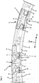
- Fig. 2 shows one to Fig. 1 similar representation in a plan view in the axial direction AR of a gas turbine.
- the components 22 may be components of a turbine intermediate housing, in particular so-called fairings or panels, which are arranged next to one another in the circumferential direction. These components are used in this application, in particular in the claims and later with reference to the Fig. 3 also addressed as second components.
- the second components 22 define a hot gas leading channel, which is indicated by the reference numeral 24.
- the channel 24 is sealed at the transition between two second components 22 by an overlap region 26.
- a radially outer overlapping section 28 of the one second component 22 and a radially inner overlapping section 30 of the adjacent (other) second component overlap.
- the distance 16 can also be seen in the abutting area of the two sealing arrangements 10 or their sealing elements 12. As already described with reference to FIGS Fig. 1 explained, this distance or gap 16 is covered by a further sealing body 18. Furthermore, the optional spring elements 20 are also visible, which are adapted to press the respective sealing elements 12 in particular in the axial direction against a sealing point.
- a respective sealing element 12, the associated part of the sealing body 18 and an optional spring element 20 have respective openings 32, 34 and 36, which in particular also from the Fig. 1 is apparent.
- the opening 32 of a sealing element 12 is formed circular or oblong-shaped.
- the opening 36 of a spring element 20 may be formed krei s-shaped or elongated hole-shaped.
- the opening 34 of the sealing body 18 is in particular U-shaped and open on one side in the circumferential direction. Through all openings 32, 34, 36 is in the assembled state of the seal assemblies 10 each have a bolt 38 therethrough.
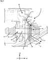
- FIG. 3 shows by way of example here a radially outer region of a gas turbine, in particular an aircraft gas turbine, a first component 40 having a first flange section 42 can be seen.
- the first component 40 is in particular a housing component of the gas turbine.
- the sealing arrangement 10 comprises a second component 22 with a second flange portion 44.
- the second component 22 is in particular a part of a turbine intermediate housing, such as a fairing or a panel.
- the bolt 38 is in particular a bolt on which a nut 46 is screwed, so that the first component 40 and the second component 22 can be releasably connected to each other or are connected.
- connection between the first component 40 and the second component 22 includes along the bolt 38 further disc-like or ring-like or sleeve-like elements, which are summarized and simplified by the reference numeral 48.
- a gap or gap AB to be sealed is provided or provided.
- the distance AB is in the Fig. 3 exemplified in the radial direction RR.
- the distance could also be drawn inclined to the radial direction RR between the first flange portion 42 and the second flange portion 44.
- the distance AB must be sealed in a turbomachine, such as a gas turbine, in particular an aircraft gas turbine, it being noted that the first component 40 and the second component 22 move relative to each other due to thermal influences of hot gas flowing through the gas turbine.
- the second component 22 limits radially inwardly a hot gas-carrying annular channel, wherein the hot gas flows substantially along a direction which is indicated by a double arrow SR.
- the sealing arrangement 10 For covering or sealing the distance or gap AB, the sealing arrangement 10 comprises the sealing element 12.
- the sealing element 12 has a coupling section 50. In the coupling portion 50, the opening 32 is provided, through which the bolt 38 passes.
- the seal member 12 further includes a first seal portion 52 and a second seal portion 54.
- the first seal portion 52 abuts against the first member 40. In particular, it bears against a rounding section 56.
- the second sealing section 54 rests against the second component 22, in particular at the second flange section 44.
- the sealing element 12 thus obstructs or prevents with its two Sealing sections 52, 54, the passage of fluid through the formed between the first member 40 and the second member 22 distance AB.
- the first seal portion 52 and the second seal portion 54 are arranged inclined to each other. As seen from the sectional view of Fig. 3 can be seen, the sealing element 12 in the region of the two sealing portions 52, 54 V-shaped.
- the first seal portion 52 and the second seal portion 54 are connected to each other via a bent connecting portion 57. They form an angle of between about 60 ° and 120 °, more preferably between about 80 ° and 110 °.
- the first sealing portion 52 and the second sealing portion are substantially orthogonal to each other, ie they enclose an angle of about 90 °.
- the angle specifications relate in particular to a position of the sealing sections 52, 54 relative to one another in a stationary operating state of a gas turbine (cold state). It is clear that the angular position can change somewhat due to the changing pressure conditions and / or the changing temperature conditions in the operation of the gas turbine. As a result, for example, an angle of originally 90 °, for example, be slightly larger or smaller.
- the two sealing sections 52, 54 are usually pressed against the first component 40 and the second component 22 solely by the pressure difference.
- the first flange portion 42 facing side of the sealing member 12 is a lower pressure than on the right side. Due to this pressure difference, the V-shaped sealing portions 52, 54 are pressed against the two components 40, 22, in particular against the second flange portion 44 and against the rounding portion 56 which is associated with the first component 40.
- the sealing body 18 is also visible, which overlaps the sealing element 12 in the axial direction.
- Fig. 4 For the first component 40, a representative part of the rounding section 56 is shown. For the second component 22 is still a part of the second flange portion 44 can be seen. between the first component 40 and the second component 22 and between the rounding section 56 and the second flange 44, the distance AB is located.
- Part A) shows a relative center position of the two components 40, 22 to each other. Starting from this central position relative end positions of the two components 40, 22 are shown to each other in the subfigures B) and C), wherein in part figure B) a maximum distance ABx is present and in subfigure C) a minimum distance ABn.
- the opening 32 in the coupling portion 50 is elongate or designed as a slot.
- the sealing element 12 is arranged on a securing portion 60.
- the securing portion 60 is a type of collar or sleeve that surrounds the bolt.
- the securing section 60 can be embodied as a separate part from the bolt 38 or from its shaft 58, which part can be slidably received on the shaft 58.
- the securing portion 60 has a coupling portion 61 and a holding portion 63.
- the coupling portion 61 has a larger diameter than the shaft 58 of the bolt 38.
- the holding portion 63 has a slightly larger diameter than the coupling portion 61.
- the securing portion 60 can therefore also be described as mushroom-shaped, wherein the coupling portion 61 forms the stem and the holding portion 63 the hat.
- the diameter of the opening 32 of the sealing element 12 is slightly larger in the radial direction RR than the diameter of the coupling portion 61 of the securing portion 60.
- the holding portion 63 has a larger diameter than the opening 32.
- the spring element 20 has an opening 34 which is elongate or elongated in the radial direction RR.
- the spring element 20 comprises a pressure section 62, a connecting section 64 and a support section 66.
- the support portion 66 is bent in a U-shape, so that the spring element 20 abuts with a leg 67 of the U-shaped support portion on the second flange portion.
- the spring element 20 lies with its connecting portion 64, in which the opening 64 is provided, on the securing portion 60, in particular on the holding portion 63.
- the connecting portion 64 has a slightly bent or bent shape, such that it is slightly concave in the direction of the components 40, 22 to be sealed (see in particular 4 A) and B) , With its convex side, the spring element 20 is supported on the holding portion 63 of the securing portion 60.
- the pressure portion 62 is formed convex to the sealing member 12, in particular to its connecting portion 57.
- the spring element 20 is configured to press the sealing element 12, in particular its sealing sections 52, 54, against the first component 40 and the second component 22, in particular against the rounding section 56 and the second flange section 44, respectively.
- the corresponding elastic biasing force is applied in particular by the fact that the spring element 20, in particular its connecting portion 64 is bent or bent towards the sealing element 12.
- the spring element 20 In each relative position of the two components 44, 20 to each other and a corresponding position of the sealing element 12, as shown in FIGS. A) to C), the spring element 20 also assumes a modified relative position. Furthermore, the spring element 20 at a smaller distance ABn ( Fig. 4C ) elastically deformed against the biasing force, in particular slightly bent. The support section 66, in particular its leg 67, remains in contact with the second component 22 or its second flange section 44 in each relative position of the spring element 20.
- the spring element 20 In the axial direction AR, the spring element 20 is received between the holding portion 63 of the securing portion 60 of the bolt 38 and the sealing element 12.
- the sealing element 12 is arranged in the axial direction AR between the spring element 20 and the second flange portion 44.
- the seal assembly 10 does not necessarily have to have a spring element 20.
- the function of the seal can also be achieved by a sealing element 12 without associated spring element 20. In that regard, one could, for example, in the Fig. 4 simply think away the spring element 20, without this, the operation of the sealing element 12 is changed.
- the sectional view of the Fig. 5 shows the insertion of the bolt 38 in a corresponding opening 68 which is formed in the flange portion 44 of the second component 22.
- the opening 68 has a slightly larger diameter than the shaft 58 of the bolt 38. This allows the bolt 38, as in Fig. 5 shown inserted in an inclined position through the opening 68.
- the centering of the bolt 38 within the opening 68 is carried out by the sliding of a sleeve-like element 48, as shown in the Fig. 3 is apparent.
- the optional spring element 20 may already be in connection with the shaft 58 during insertion of the bolt 38.
Landscapes
- Engineering & Computer Science (AREA)
- Mechanical Engineering (AREA)
- General Engineering & Computer Science (AREA)
- Physics & Mathematics (AREA)
- Fluid Mechanics (AREA)
- Turbine Rotor Nozzle Sealing (AREA)
- Gasket Seals (AREA)
Abstract
Description
- Die vorliegende Erfindung betrifft eine Dichtungsanordnung für eine Gasturbine, insbesondere Fluggasturbine, umfassend: ein erstes Bauteil mit einem ersten Flanschabschnitt und ein zweites Bauteil mit einem zweiten Flanschabschnitt, wobei das erste Bauteil und das zweite Bauteil im Bereich des ersten Flanschabschnitts und des zweiten Flanschabschnitts mittels einer Schraubverbindung lösbar miteinander gekoppelt sind, wobei zwischen dem ersten Bauteil, insbesondere einem Verrundungsabschnitt und dem zweiten Bauteil, insbesondere dem zweiten Flanschabschnitt, ein veränderlicher Abstand vorgesehen ist, der durch wenigstens ein Dichtungselement wenigstens teilweise abgedichtet wird.
- In Gasturbinen, insbesondere Fluggasturbinen, ist es erforderlich, dass statische Bauteile abgedichtet werden, die großen thermischen Schwankungen unterliegen und entsprechend auch bedeutende thermisch induzierte Verschiebungen bzw. Bewegungen aufweisen. Herkömmlicherweise werden solche Abdichtungen durch sogenannte Dichtplatten erreicht, die über einen in der Gasturbine vorhandenen Druckunterschied an einer Dichtstelle gegen entsprechende Dichtflächen gedrückt werden. Dabei ist zu beachten, dass ein Abstand zwischen den Dichtflächen in der Regel ziemlich groß ist, um bei gleichzeitiger Dichtwirkung auch die thermomechanischen Deformationen aufnehmen zu können. Insbesondere ist der Abstand zwischen den Dichtflächen größer als eine maximal erwartbare Verschiebung der Bauteile relativ zueinander aufgrund der thermischen Einflüsse. Entsprechend müssen die Dichtflächen, an denen die Dichtplatten anliegen relativ groß gewählt werden, um in jedem (B e-triebs-)Zustand der Gasturbine die gewünschte Abdichtung zu erreichen.
- Aufgabe der Erfindung ist es, eine verbesserte Dichtungsanordnung vorzusehen, bei der eine Abdichtung auch bei großen Verschiebungen zuverlässig bereitgestellt werden kann.
- Zur Lösung dieser Aufgabe wird vorgeschlagen, dass das Dichtungselement einen am ersten Bauteil, insbesondere am Verrundungsabschnitt anliegenden ersten Dichtungsabschnitt und einen am zweiten Bauteil, insbesondere am zweiten Flanschabschnitt anliegenden zweiten Dichtungsabschnitt aufweist, wobei der erste Dichtungsabschnitt und der zweite Dichtung s-abschnitt miteinander verbunden sind und geneigt zueinander angeordnet sind.
- Durch eine geneigte Anordnung der beiden Dichtungsabschnitte kann auf eine vollflächige Anlage an Dichtflächen wie bei bekannten Dichtplatten verzichtet werden. Entsprechend kann die Dichtfläche, also der Bereich, in dem die Dichtungsabschnitte an den beiden Bauteilen, insbesondere dem Verrundungsabschnitt und dem zweiten Flanschabschnitt anliegen, reduziert werden, so dass die Dichtungsanordnung insgesamt reduziert werden kann.
- Das Dichtungselement kann relativ zum ersten Bauteil und relativ zum zweiten Bauteil verschiebbar sein. Durch die relative Verschiebbarkeit können Bewegungen der Bauteile aufgrund thermischer Einwirkung ausgeglichen werden bei Beibehaltung der Dichtwirkung.
- Das Dichtungselement kann einen sich an den zweiten Dichtungsabschnitt anschließenden Kopplungsabschnitt aufweisen, wobei im Kopplungsabschnitt eine Öffnung vorgesehen ist, durch die ein Schaft eines Bolzens der Schraubverbindung hindurchgeführt ist. Dabei kann der Schaft des Bolzens einen Sicherungsabschnitt aufweisen, der einen größeren Durchmesser als der Schaft aufweist, derart, dass eine Bewegung des Dichtungselements entlang der Längsrichtung des Schafts nur eingeschränkt möglich ist. Ferner kann die Öffnung als Langloch ausgebildet sein. Dabei kann das Langloch derart bemessen sein, dass das Dichtungselement in Abhängigkeit des veränderlichen Abstands oder des entsprechenden abzudichtenden Spalts zwischen dem ersten Flanschabschnitt und dem zweiten Flanschabschnitt verschiebbar ist.
- Durch eine derartige Ausgestaltung des Kopplungsabschnitts mit Öffnung kann das Dichtungselement in einfacher Weise an dem Schaft eines Schraubbolzens angeordnet werden und beim Zusammenschrauben der beiden Flanschabschnitte in eine Einbauposition gebracht werden. Der Sicherungsabschnitt kann eine Art Manschette oder Hülse sein. Dabei kann ein Halteabschnitt des Sicherungsabschnitts für das Dichtungselement als eine Art Anschlag dienen, um das Dichtungselement sicher in Position zu halten. Das Langloch ermöglicht die Bewegung des Dichtungselements relativ zum Schaft bzw. relativ zum Sicherungsabschnitt und somit auch relativ zu den beiden Bauteilen.
- In anderen Ausführungsformen kann die Öffnung auch beliebige andere Formen aufweisen und größer als der Querschnitt des Bolzens sein. Dies gestattet ebenfalls die vorgenannte Verschiebbarkeit.
- Die Dichtungsanordnung kann ferner ein Federelement umfassen, das dazu eingerichtet ist, den ersten Dichtungsabschnitt und den zweiten Dichtungsabschnitt in Richtung des ersten Bauteils bzw. Flanschabschnitts und des zweiten Bauteils bzw. Flanschabschnitts zu drücken. Dabei kann das Federelement eine Öffnung aufweisen, insbesondere in Form eines Langlochs, durch die der Schaft des Bolzens der Schraubverbindung hindurchgeführt ist. Ferner wird vorgeschlagen, dass das Federelement zwischen dem Sicherungsabschnitt des Schafts und dem Dichtungselement angeordnet ist.
- Das Dichtungselement wird, wie die herkömmlichen Dichtplatten, aufgrund von Druckunterschieden gegen die Flanschabschnitte gedrückt. Um eine Abdichtung aber auch bei geringen Druckunterschieden bzw. im Stillstand der Gasturbine sicherstellen zu können, kann das Federelement eingesetzt werden. Das Federelement ist dabei so ausgeführt, dass es in Richtung der abzudichtenden Stelle vorgespannt ist, so dass es auf das Dichtungselement eine entsprechende Druckkraft ausübt.
- Das Federelement kann dabei am ersten Flanschabschnitt oder am zweiten Flanschabschnitt sowie am Sicherungsabschnitt des Schafts abgestützt sein. Durch diese Lagerung des Federelements können die auf das Dichtungselement ausgeübten Kräfte optimal in die umgebende Struktur der Bauteile abgeleitet werden.
- Der erste Dichtungsabschnitt und der zweite Dichtungsabschnitt können im Wesentlichen V-förmig zueinander angeordnet sein, insbesondere einen Winkel bilden, der vorzugsweise zwischen etwa 60° und 120°, besonders bevorzugt etwa zwischen 80° und 110° liegt.
Dabei können der erste Dichtungsabschnitt und der zweite Dichtungsabschnitt durch einen gebogenen Verbindungsabschnitt verbunden sein, wobei der Verbindungsabschnitt in Richtung zu dem ersten Flanschabschnitt oder dem zweiten Flanschabschnitt hin konvex ausgebildet ist. Es wird insbesondere vorgeschlagen, dass eine konvexe Seite des Verbindungsabschnitt einem geringeren Druck im Betrieb der Gasturbine ausgesetzt ist, als die komplementäre konkave Seite des Verbindungsabschnitts. Der gebogene Verbindungsabschnitt ermöglicht auch einer elastische Auslenkung der beiden Dichtungsabschnitte zueinander, so dass die Dichtungsabschnitte sich in jedem Betriebszustand der Gasturbine bzw. in jeder Relativ stellung der beiden Bauteile zueinander eine optimale Position einnehmen können. - Die Erfindung betrifft ferner auch eine Gasturbine, insbesondere Fluggasturbine, mit einem Turbinenzwischengehäuse, wobei die Gasturbine entlang der Umfangsrichtung mehrere oben beschriebene Dichtungsanordnungen umfasst, wobei das erste Bauteil einer Dichtungsanordnung ein Gehäusebauteil ist und wobei das zweite Bauteil der betreffenden Dichtungsanordnung ein Teil des Turbinenzwischengehäuses ist, insbesondere ein Panel oder Fairing des Turbinenzwischengehäuses.
- Bei einer solchen Gasturbine kann in einem Übergangsbereich von jeweils zwei Dichtungsanordnungen, die in Umfangsrichtung benachbart zueinander angeordnet sind und im Bereich einer Überlappung von zwei benachbarten Bauteilen des Turbinenzwischengehäuses angeordnet sind, wenigstens ein weiteres Dichtungselement, insbesondere ein dem Profil des Dichtungselements angepasster Dichtkörper angeordnet sein.
- Der Dichtkörper und die betreffenden Dichtungselemente der benachbarten Dichtungsanordnungen können in Axialrichtung wenigstens teilweise überlappend angeordnet sein.
- Durch die Kombination von zwei benachbarten Dichtungsanordnungen mit ihren jeweiligen Dichtungselementen und einem zusätzliche Dichtkörper können Stoßbereiche von Bauteilen im Bereich des Turbinenzwischengehäuses einfach und gut abgedichtet werden.
- In Bezug auf die Gasturbine sind Richtungsangaben wie "Axial-" bzw. "axial", "Radial-" bzw. "radial" und "Umfangs-" sind grundsätzlich auf die Maschinenachse der Gasturbine bezogen zu verstehen, sofern sich aus dem Kontext nicht explizit oder implizit etwas anderes ergibt.
- Es wird noch darauf hingewiesen, dass das erste Bauteil und das zweite Bauteil aus einem keramischen Faserverbundwerkstoff (CMC) hergestellt sein können. Das Dichtungselement und das Federelement sind bevorzugt aus einem Metall hergestellt.
- Nachfolgend wird die Erfindung unter Bezugnahme auf die anliegenden Figuren beispielhaft und nicht einschränkend beschrieben.
-
Fig. 1 zeigt in einer schematischen und vereinfachten Perspektivdarstellung zwei benachbarte Dichtungselemente einer Dichtungsanordnung mit optional zugehörigen Federelementen und einem Dichtkörper an einer Stoßstelle der beiden Dichtungselemente. -
Fig. 2 zeigt in einer schematischen und vereinfachten Draufsicht in Axialrichtung eine zurFig. 1 ähnliche Darstellung einer Dichtungsanordnung mit Dichtungselementen, optional zugehörigen Federelementen und Dichtkörpern. -
Fig. 3 zeigt eine Dichtungsanordnung in einer schematischen und vereinfachten Schnittdarstellung etwa entlang einer Schnittlinie 111-111 derFig. 2 . -
Fig. 4 zeigt die Schnittdarstellung der Dichtungsanordnung derFig. 3 in einer weiter vereinfachten Prinzipdarstellung, wobei in den Teilfiguren A) bis C) unterschiedliche Relativstellungen von Bauteilen an der Dichtstelle illustriert sind. -
Fig. 5 zeigt in einer vereinfachten und schematischen Schnittdarstellung einen temporären Zustand, wenn ein Dichtungselement mit optionalem Federelement mittels eines Bolzens am betreffenden Bauteil angeordnet wird. -
Fig. 1 zeigt in einer vereinfachten und schematischen Perspektivdarstellung zwei Dichtung s-elemente 12, die Teil einer jeweiligen in denFig. 2 und3 genauer dargestellten Dichtungsanordnung 10 sind. Die Dichtungselemente 12 sind entlang einer Umfangsrichtung UR einer hier nicht weiter dargestellten Gasturbine, insbesondere Fluggasturbine, nebeneinander angeordnet. Zwischen zwei benachbarten Dichtungselementen 12 ist eine Stoßstelle 14 ausgebildet. An dieser Stoßstelle 14 ist zwischen den beiden Dichtungselementen 12, insbesondere aufgrund einer überlappenden Anordnung von Bauteilen der Gasturbine, insbesondere von Bauteilen eines Turbinenzwischengehäuses, ein Abstand 16 ausgebildet. Dieser Abstand 16 wird durch einen Dichtkörper 18 abgedeckt bzw. überbrückt. In derFig. 1 sind ferner optional für die Dichtungsanordnung 10 einsetzbare Federelemente 20 dargestellt, die dazu eingerichtet sind, das jeweilige Dichtungselement 12 in Richtung einer abzudichtenden Stelle zu drücken. -
Fig. 2 zeigt eine zurFig. 1 ähnliche Darstellung in einer Draufsicht in Axialrichtung AR einer Gasturbine. In derFig. 2 sind jeweilige Bauteile 22 der betreffenden Dichtungsanordnung ersichtlich. Die Bauteile 22 können Bauteile eines Turbinenzwischengehäuses sein, insbesondere sogenannte Fairings oder Panels, die in Umfangsrichtung nebeneinander angeordnet sind. Diese Bauteile werden in dieser Anmeldung, insbesondere in den Ansprüchen und später unter Bezugnahme auf dieFig. 3 auch als zweite Bauteile angesprochen. - In Radialrichtung RR innen begrenzen die zweiten Bauteile 22 einen Heißgas führenden Kanal, was durch das Bezugszeichen 24 angedeutet ist. In Radialrichtung wir der Kanal 24 am Übergang zwischen zwei zweiten Bauteilen 22 durch einen Überlappungsbereich 26 abgedichtet. Dabei überlagern sich ein radial äußerer Überlappungsabschnitt 28 des einen zweiten Bauteils 22 und ein radial innerer Überlappungsabschnitt 30 des benachbarten (anderen) zweiten Bauteils.
- Aus der
Fig. 2 ist ferner auch der Abstand 16 ersichtlich im Stoßbereich der beiden Dichtungsanordnungen 10 bzw. deren Dichtungselementen 12. Wie bereits unter Bezugnahme auf dieFig. 1 erläutert, wird dieser Abstand bzw. Zwischenraum 16 durch einen weiteren Dichtkörper 18 abgedeckt. Ferner sind ebenfalls die optionalen Federelemente 20 ersichtlich, die dazu eingerichtet sind, die jeweiligen Dichtungselemente 12 insbesondere in Axialrichtung gegen eine Dichtstelle zu drücken. - Bezogen auf die Axialrichtung, die in
Fig. 2 orthogonal zur Zeichnungsebene liegt, sind jeweils ein Federelement 20, ein Dichtkörper 18 und ein Dichtungselement 12 hinter- bzw. nebeneinander angeordnet. Aus rein darstellerischen Gründen zur Verbesserung der Verständlichkeit der Zeichnung sind in derFig. 2 oberhalb des linken Überlappungsbereichs 26 die beiden Dichtungselemente 12 durch eine dicker gestrichelte Linie (Kontur) hervorgehoben. Beim rechten Überlappungsbereich 26 ist die Kontur des Dichtkörpers 18 dicker gestrichelt dargestellt. - Ein jeweiliges Dichtungselement 12, der zugehörige Teil des Dichtkörpers 18 und ein optionales Federelement 20 weisen jeweilige Öffnungen 32, 34 und 36 auf, was insbesondere auch aus der
Fig. 1 ersichtlich ist. Die Öffnung 32 eines Dichtelements 12 ist dabei kreisförmig oder langlochförmig ausgebildet. Auch die Öffnung 36 eines Federelements 20 kann krei s-förmig oder langlochförmig ausgebildet sein. Die Öffnung 34 des Dichtkörpers 18 ist insbesondere U-förmig ausgebildet und in Umfangsrichtung einseitig offen. Durch alle Öffnungen 32, 34, 36 geht im zusammengesetzten Zustand der Dichtungsanordnungen 10 jeweils ein Bolzen 38 hindurch. - Die Dichtungsanordnung 10 wird nun in Bezug auf die Schnittdarstellung der
Fig. 3 weiter erläutert, wobei der Schnitt etwa entsprechend den Schnittlinien III-III derFig. 1 undFig. 2 gewählt ist. - Aus der Schnittdarstellung ist in einem oberen Bereich der
Figur 3 , der hier beispielhaft einen radial äußeren Bereich einer Gasturbine, insbesondere Fluggasturbine, zeigt, ein erstes Bauteil 40 mit einem ersten Flanschabschnitt 42 ersichtlich. Das erste Bauteil 40 ist insbesondere ein Gehäusebauteil der Gasturbine. Ferner umfasst die Dichtungsanordnung 10 ein zweites Bauteil 22 mit einem zweiten Flanschabschnitt 44. Das zweite Bauteil 22 ist insbesondere ein Teil eines Turbinenzwischengehäuses, etwa ein Fairing oder ein Panel. Durch die beiden Flanschabschnitte 42, 44 ist der Bolzen 38 hindurch geführt. Der Bolzen 38 ist insbesondere ein Schraubbolzen, auf den eine Mutter 46 aufgeschraubt ist, so dass das erste Bauteil 40 und das zweite Bauteil 22 miteinander lösbar verbunden werden können bzw. verbunden sind. - Die Verbindung zwischen dem ersten Bauteil 40 und dem zweiten Bauteil 22 umfasst entlang des Bolzens 38 noch weitere scheibenartige oder ringartige oder hülsenartige Elemente, die zusammenfassend und vereinfacht mit dem Bezugszeichen 48 gekennzeichnet sind.
- Zwischen dem ersten Bauteil 40 und dem zweiten Bauteil 22 ist ein Abstand oder ein abzudichtender Spalt AB vorgesehen bzw. vorhanden. Der Abstand AB ist in der
Fig. 3 beispielhaft in Radialrichtung RR eingezeichnet. Der Abstand könnte aber auch geneigt zur Radialrichtung RR zwischen dem ersten Flanschabschnitt 42 und dem zweiten Flanschabschnitt 44 eingezeichnet werden. Der Abstand AB muss in einer Strömungsmaschine, wie einer Gasturbine, insbesondere Fluggasturbine abgedichtet werden, wobei zu beachten ist, dass sich das erste Bauteil 40 und das zweite Bauteil 22 relativ zueinander bewegen aufgrund thermischer Einflüsse von Heißgas, das die Gasturbine durchströmt. Im vorliegenden Beispiel begrenzt das zweite Bauteil 22 nach radial innen einen Heißgas führenden Ringkanal, wobei das Heißgas im Wesentlichen entlang einer Richtung strömt, die durch einen Doppelpfeil SR angedeutet ist. - Zur Überdeckung bzw. Abdichtung des Abstandes bzw. Spalts AB umfasst die Dichtungsanordnung 10 das Dichtungselement 12. Das Dichtungselement 12 weist einen Kopplungsabschnitt 50 auf. Im Kopplungsabschnitt 50 ist die Öffnung 32 vorgesehen, durch die der Bolzen 38 hindurchgeht. Das Dichtungselement 12 umfasst ferner einen ersten Dichtungsabschnitt 52 und einen zweiten Dichtungsabschnitt 54. Der erste Dichtungsabschnitt 52 liegt am ersten Bauteil 40 an. Insbesondere liegt er an einem Verrundungsabschnitt 56 an Der zweite Dichtungsabschnitt 54 liegt am zweiten Bauteil 22, insbesondere am zweiten Flanschabschnitt 44 an. Das Dichtungselement 12 behindert bzw. verhindert also mit seinen beiden Dichtungsabschnitten 52, 54 das Durchströmen von Fluid durch den zwischen dem ersten Bauteil 40 und dem zweiten Bauteil 22 gebildeten Abstand AB.
- Der erste Dichtungsabschnitt 52 und der zweite Dichtungsabschnitt 54 sind geneigt zueinander angeordnet. Wie aus der Schnittdarstellung der
Fig. 3 ersichtlich, ist das Dichtungselement 12 im Bereich der beiden Dichtungsabschnitte 52, 54 V-förmig ausgebildet. Der erste Dichtungsabschnitt 52 und der zweite Dichtungsabschnitt 54 sind über einen gebogenen bzw. gekrümmten Verbindungsabschnitt 57 miteinander verbunden. Sie bilden dabei einen Winkel, von zwischen etwa 60° und 120°, besonders bevorzugt etwa zwischen 80° und 110°. Im dargestellten Beispiel stehen der erste Dichtungsabschnitt 52 und der zweite Dichtungsabschnitt im Wesentlichen orthogonal zueinander, d.h. sie schließen einen Winkel von etwa 90° ein. Die Winkelangaben beziehen sich insbesondere auf eine Stellung der Dichtungsabschnitte 52, 54 zueinander in einem ruhenden Betriebszustand einer Gasturbine (kalter Zustand). Es ist klar, dass sich die Winkellage aufgrund der sich verändernden Druckverhältnisse oder/und der sich verändernden Temperaturverhältnisse im Betrieb der Gasturbine etwas verändern kann. Hierdurch kann dann beispielsweise ein Winkel von ursprünglich 90° beispielsweise etwas größer oder kleiner werden. - Die beiden Dichtungsabschnitte 52, 54 werden üblicherweise alleine durch den Druckunterschied gegen das erste Bauteil 40 bzw. das zweite Bauteil 22 gedrückt. Im vorliegenden Beispiel herrscht bezogen auf die
Fig. 3 im Betrieb der Gasturbine auf der linken Seite, also der dem ersten Flanschabschnitt 42 zugewandten Seite des Dichtungselements 12 ein geringerer Druck als auf der rechten Seite. Aufgrund dieses Druckunterschieds werden die V-förmig zueinander ausgebildeten Dichtungsabschnitte 52, 54 gegen die beiden Bauteile 40, 22 gepresst, insbesondere gegen den zweiten Flanschabschnitt 44 und gegen den Verrundungsabschnitt 56, der dem ersten Bauteil 40 zugeordnet ist. In derFig. 3 ist ferner auch der Dichtkörper 18 sichtbar, der das Dichtungselement 12 in Axialrichtung überlappt. - Unter Bezugnahme auf die
Fig. 4 wird nachfolgend die Anbringung des Dichtungselements 12 an dem Bolzen 38 erläutert werden. Ferner wird auch die Funktion des optionalen Federelements 20, das auch in derFig. 3 dargestellt ist, genauer beschrieben. Die Darstellungen inFig. 4 sind verglichen mit der Schnittdarstellung derFig. 3 stark vereinfacht und es sind nur die für die Funktionsbeschreibung relevanten Bauteile dargestellt. - In
Fig. 4 ist für das erste Bauteil 40 stellvertretend ein Teil des Verrundungsabschnitts 56 dargestellt. Für das zweite Bauteil 22 ist noch ein Teil des zweiten Flanschabschnitts 44 ersichtlich. zwischen dem ersten Bauteil 40 und dem zweiten Bauteil 22 bzw. zwischen dem Verrundungsabschnitt 56 und dem zweiten Flanschabschnitt 44 ist der Abstand AB eingezeichnet. Teilfigur A) zeigt eine relative Mittellage der beiden Bauteile 40, 22 zueinander. Ausgehend von dieser Mittellage sind in den Teilfiguren B) und C) relative Endlagen der beiden Bauteile 40, 22 zueinander dargestellt, wobei in Teilfigur B) ein maximaler Abstand ABx vorhanden ist und in Teilfigur C) ein minimaler Abstand ABn. Durch die geneigte Anordnung der beiden Dichtungsabschnitte 52, 54 zueinander, kann der sich verändernde Abstand AB, ABx, ABn zuverlässig überbrückt und abgedichtet werden. - Damit das Dichtungselement 12 sich dem verändernden Abstand AB, ABx, ABn in seiner Relativlage zum Bolzen 38 bzw. den Bauteilen 40, 22 anpassen kann, ist die Öffnung 32 im Kopplungsabschnitt 50 länglich bzw. als Langloch ausgeführt. Das Dichtungselement 12 ist an einem Sicherungsabschnitt 60 angeordnet. Der Sicherungsabschnitt 60 ist eine Art Manschette oder Hülse, die den Bolzen umgibt. Der Sicherungsabschnitt 60 kann als ein vom Bolzen 38 bzw. von dessen Schaft 58 gesondertes Teil ausgeführt sein, das am Schaft 58 verschiebbar aufgenommen sein kann. Dabei weist der Sicherungsabschnitt 60 einen Kopplungsabschnitt 61 und einen Halteabschnitt 63 auf. Der Kopplungsabschnitt 61 weist einen größeren Durchmesser auf als der Schaft 58 des Bolzens 38. Der Halteabschnitt 63 weist einen etwas größeren Durchmesser als der Kopplungsabschnitt 61 auf. Der Sicherungsabschnitt 60 kann also auch als pilzförmig beschrieben werden, wobei der Kopplungsabschnitt 61 den Stiel bildet und der Halteabschnitt 63 den Hut.
- Der Durchmesser der Öffnung 32 des Dichtungselements 12 ist in Radialrichtung RR etwas größer ist als der Durchmesser des Kopplungsabschnitts 61 des Sicherungsabschnitts 60. Der Halteabschnitt 63 weist einen größeren Durchmesser als die Öffnung 32 auf. Durch den Sicherungsabschnitt 60 bzw. den Kopplungsabschnitt 61 und den Halteabschnitt 63 ist das Dichtungselement 12 in seiner Relativbewegung in Axialrichtung AR begrenzt. Hierdurch kann verhindert werden, dass sich das Dichtungselement 12 trotz seiner relativen Beweglichkeit unerwünscht weit weg von der abzudichtenden Stelle entfernen kann, so dass die gewünschte Dichtwirkung negativ beeinträchtigt wird. Das Dichtungselement 12 ist somit in Axialrichtung AR zwischen dem Halteabschnitt 63 und dem zweiten Bauteil 22 bzw. dem zweiten Flanschabschnitt 44 aufgenommen.
- In der
Fig. 4 ist auch das optionale Federelement 20 dargestellt. Das Federelement 20 weist eine in Radialrichtung RR längliche bzw. als Langloch ausgebildete Öffnung 34 auf. Das Federelement 20 umfasst einen Druckabschnitt 62, einen Verbindungsabschnitt 64 und einen Stützabschnitt 66 auf. Der Stützabschnitt 66 ist u-förmig gebogen, so dass das Federelement 20 mit einem Schenkel 67 des U-förmigen Stützabschnitts am zweiten Flanschabschnitt anliegt. Ferner liegt das Federelement 20 mit seinem Verbindungsabschnitt 64, in dem auch die Öffnung 64 vorgesehen ist, am Sicherungsabschnitt 60, insbesondere am Halteabschnitt 63 an. Der Verbindungsabschnitt 64 weist eine leicht gebogene bzw. geknickte Form auf, derart, dass er in Richtung der abzudichtenden Bauteile 40, 22 leicht konkav ausgebildet ist (siehe insbesondereFig. 4 A) und B) . Mit seiner konvexen Seite stützt sich das Federelement 20 am Halteabschnitt 63 des Sicherungsabschnitts 60 ab. Der Druckabschnitt 62 ist zum Dichtungselement 12, insbesondere zu dessen Verbindungsabschnitt 57 hin konvex ausgebildet. Das Federelement 20 ist dazu eingerichtet, das Dichtungselement 12, insbesondere dessen Dichtungsabschnitte 52, 54 gegen das erste Bauteil 40 bzw. das zweite Bauteil 22, insbesondere gegen den Verrundungsabschnitt56 bzw. den zweiten Flanschabschnitt 44 zu drücken. Die entsprechende elastische Vorspannkraft wird dabei insbesondere dadurch aufgebracht, dass das Federelement 20, insbesondere dessen Verbindungsabschnitt 64 zum Dichtungselement 12 hin geknickt bzw. gebogen ist. - In jeder Relativposition der beiden Bauteile 44, 20 zueinander und einer entsprechenden Lage des Dichtungselements 12, wie dies in den Fig. A) bis C) dargestellt ist, nimmt das Federelement 20 ebenfalls eine veränderte Relativstellung ein. Ferner wird das Federelement 20 bei geringerem Abstand ABn (
Fig. 4C ) entgegen der Vorspannkraft elastisch verformt, insbesondere etwas aufgebogen. Der Stützabschnitt 66, insbesondere dessen Schenkel 67 bleibt dabei in jeder Relativposition des Federelements 20 in Kontakt mit dem zweiten Bauteil 22, bzw. dessen zweiten Flanschabschnitt 44. - In Axialrichtung AR ist das Federelement 20 zwischen dem Halteabschnitt 63 des Sicherungsabschnitts 60 des Bolzens 38 und dem Dichtungselement 12 aufgenommen. Das Dichtungselement 12 ist in Axialrichtung AR zwischen dem Federelement 20 und dem zweiten Flanschabschnitt 44 angeordnet. Somit kann durch das Federelement 20 in jedem Betriebszustand der Gasturbine und entsprechend in jeder Relativstellung der Bauteile 44, 20 zueinander ein ausreichender, gegebenenfalls zusätzlicher Druck (zum herrschenden Druckunterschied des umgebenden Fluids) auf das Dichtungselement 12 ausgeübt werden, um die gewünschte Abdichtung im Bereich des Abstands AB zu erreichen bzw. zu verstärken. Das Federelement 12 stellt auch sicher, dass das Dichtungselement 12 bei geringem Druckunterschied auf die abzudichtende Stell zwischen den beiden Bauteilen 40, 22 gedrückt wird.
- Es wird darauf hingewiesen, dass die Dichtungsanordnung 10 nicht zwingend ein Federelement 20 aufweisen muss. Die Funktion der Abdichtung kann auch durch ein Dichtungselement 12 ohne zugeordnetes Federelement 20 erreicht werden. Insoweit könnte man sich beispielsweise in der
Fig. 4 das Federelement 20 einfach wegdenken, ohne dass hierdurch die Funktionsweise des Dichtungselements 12 verändert wird. - Die Schnittdarstellung der
Fig. 5 zeigt das Einführen des Bolzens 38 in eine entsprechende Öffnung 68, die im Flanschabschnitt 44 des zweiten Bauteils 22 ausgebildet ist. In dieser Darstellung ist auch der Aufbau des Sicherungsabschnitts 60 mit dem Kopplungsabschnitt 61 und dem Halteabschnitt 63 besser erkennbar als in der Schnittdarstellung derFig. 3 . Die Öffnung 68 weist einen etwas größeren Durchmesser auf als der Schaft 58 des Bolzens 38. Hierdurch kann der Bolzen 38, wie inFig. 5 dargestellt, in einer geneigten Stellung durch die Öffnung 68 eingeführt werden. Die Zentrierung des Bolzens 38 innerhalb der Öffnung 68 erfolgt durch das Aufschieben eines hülsenartigen Elements 48, wie dies in derFig. 3 ersichtlich ist. Beim Einführen des Bolzens 38 ist dessen Schaft 58 bereits durch die Öffnung 32 des Dichtungselements 12 hindurch geführt, so dass der Einbau vereinfacht ist. Auch das optionale Federelement 20 kann beim Einführen des Bolzens 38 bereits mit dessen Schaft 58 in Verbindung stehen. Sobald der Bolzen 38 durch die Öffnung 68 hindurch eingeführt worden ist, stößt der Sicherungsabschnitt 60 mit seinem Kopplungsabschnitt 61 am ersten Flanschabschnitt 44 an, so dass ein weiteres Einführen des Bolzens 38 nicht mehr möglich ist. Anschließend kann durch Anbringen der weiteren aus derFig. 3 ersichtlichen Bauteile, wie ringartige bzw. hülsenartige Elemente 38 und Mutter 46 die Verbindung endgültig hergestellt werden. - Der Vollständigkeit halber wird noch darauf hingewiesen dass in den
Fig. 3 und5 auch der weitere Dichtkörper 18 jeweils eingezeichnet ist. In derFig. 4 ist der Dichtkörper 18 aus Gründen der vereinfachten Darstellung nicht gezeigt. -
- 10
- Dichtungsanordnung
- 12
- Dichtungselement
- 14
- Stoßstelle
- 16
- Abstand
- 18
- Dichtkörper
- 20
- Federelement
- 22
- zweites Bauteil
- 24
- Heißgas führender Kanal
- 26
- Überlappungsbereich
- 28
- Überlappungsabschnitt
- 30
- Überlappungsabschnitt
- 32
- Öffnung (des Dichtungselements)
- 34
- Öffnung (des Dichtkörpers)
- 36
- Öffnung (des Federelements)
- 38
- Bolzen
- 40
- erstes Bauteil
- 42
- erster Flanschabschnitt
- 44
- zweiter Flanschabschnitt
- 46
- Mutter
- 48
- Ring-/hülsenartiges Element
- 50
- Kopplungsabschnitt (des Dichtungselements)
- 52
- erster Dichtungsabschnitt
- 54
- zweiter Dichtungsabschnitt
- 56
- Verrundung sab schnitt
- 57
- Verbindungsabschnitt (des Dichtungselements)
- 58
- Schaft (des Bolzens)
- 60
- Sicherungsabschnitt
- 61
- Kopplungsabschnitt (des Sicherungsabschnitts)
- 62
- Druckabschnitt
- 63
- Halteabschnitt (des Sicherungsabschnitts)
- 64
- Verbindungsabschnitt
- 66
- Stützabschnitt
- 67
- Schenkel
- 68
- Öffnung (des Flanschabschnitts 44)
- AB, ABn, ABx
- Abstand
- AR
- Axialrichtung
- RR
- Radialrichtung
- UR
- Umfangsrichtung
Claims (15)
- Dichtungsanordnung (10) für eine Gasturbine, insbesondere Fluggasturbine, umfassend: ein erstes Bauteil (40) mit einem ersten Flanschabschnitt (42) und ein zweites Bauteil (22) mit einem zweiten Flanschabschnitt (44), wobei das erste Bauteil (40) und das zweite Bauteil (22) im Bereich des ersten Flanschabschnitts (42) und des zweiten Flanschabschnitts (44) mittels einer Schraubverbindung (38, 46) lösbar miteinander gekoppelt sind, wobei zwischen dem ersten Bauteil (40), insbesondere einem Verrundungsabschnitt (56), und dem zweiten Bauteil (22), insbesondere dem zweiten Flanschabschnitt (44), ein veränderlicher Abstand (AB, ABn, ABx) vorgesehen ist, der durch wenigstens ein Dichtungselement (12) wenigstens teilweise abgedichtet wird,
dadurch gekennzeichnet, dass das Dichtungselement (12) einen am ersten Bauteil (40), insbesondere am Verrundungsabschnitt (56) anliegenden ersten Dichtungsabschnitt (52) und einen am zweiten Bauteil (22), insbesondere am zweiten Flanschabschnitt (44) anliegenden zweiten Dichtungsabschnitt (54) aufweist, wobei der erste Dichtungsabschnitt (52) und der zweite Dichtungsabschnitt (54) miteinander verbunden sind und geneigt zueinander angeordnet sind. - Dichtungsanordnung nach Anspruch 1, dadurch gekennzeichnet, dass das Dichtung s-element (12) relativ zum ersten Bauteil (40) und relativ zum zweiten Bauteil (22) verschiebbar ist.
- Dichtungsanordnung nach Anspruch 1, dadurch gekennzeichnet, dass das Dichtungselement (12) einen sich an den zweiten Dichtungsabschnitt (54) anschließenden Kopplungsabschnitt (50) aufweist, wobei im Kopplungsabschnitt (50) eine Öffnung (32) vorgesehen ist, durch die ein Schaft (58) eines Bolzens (38) der Schraubverbindung hindurchgeführt ist.
- Dichtungsanordnung nach Anspruch 3, dadurch gekennzeichnet, dass an dem Schaft (58) des Bolzens ein Sicherungsabschnitt (60) angeordnet ist, der einen größeren Durchmesser als der Schaft (58) aufweist, derart, dass eine Bewegung des Dichtungselements entlang der Längsrichtung des Schafts (38) nur eingeschränkt möglich ist.
- Dichtungsanordnung nach Anspruch 3 oder 4, dadurch gekennzeichnet, dass die Öffnung (32) als Langloch ausgebildet ist.
- Dichtungsanordnung nach Anspruch 5, dadurch gekennzeichnet, dass das Langloch derart bemessen ist, dass das Dichtungselement (12) in Abhängigkeit des veränderlichen Abstands (AB, ABn, ABx) zwischen dem ersten Bauteil (40), insbesondere dessen ersten Flanschabschnitt (42, 56) und dem zweiten Bauteil (22), insbesondere dessen zweiten Flanschabschnitt (44) verschiebbar ist.
- Dichtungsanordnung nach einem der vorhergehenden Ansprüche, ferner umfassend ein Federelement (20), das dazu eingerichtet ist, den ersten Dichtungsabschnitt (52) und den zweiten Dichtungsabschnitt (54) in Richtung des ersten Flanschabschnitts (42, 56) und des zweiten Flanschabschnitts (44) zu drücken.
- Dichtungsanordnung nach Anspruch 7 und wenigstens einem der Ansprüche 3 bis 6, dadurch gekennzeichnet, dass das Federelement (20) eine Öffnung (36) aufweist, insbesondere in Form eines Langlochs, durch die der Schaft (58) des Bolzens (38) der Schraubverbindung hindurchgeführt ist.
- Dichtungsanordnung nach Anspruch 8, dadurch gekennzeichnet, dass das Federelement (20) zwischen einem Halteabschnitt (63) des Sicherungsabschnitts (60) des Schafts (58) und dem Dichtungselement (12) angeordnet ist.
- Dichtunganordnung nach Anspruch 7 oder 8, dadurch gekennzeichnet, dass das Federelement (20) am ersten Flanschabschnitt (42, 56) oder am zweiten Flanschabschnitt (44) sowie am Halteabschnitt (63) des Sicherungsabschnitts (60) abgestützt ist.
- Dichtungsanordnung nach einem der vorhergehenden Ansprüche, dadurch gekennzeichnet, dass der erste Dichtungsabschnitt (52) und der zweite Dichtungsabschnitt (54) im Wesentlichen V-förmig zueinander angeordnet sind, insbesondere einen Winkel bilden, der vorzugsweise zwischen etwa 60° und 120°, besonders bevorzugt etwa zwischen 80° und 110° liegt.
- Dichtungsanordnung nach Anspruch 11, dadurch gekennzeichnet, dass der erste Dichtungsabschnitt (52) und der zweite Dichtungsabschnitt (54) durch einen gebogenen Verbindungsabschnitt (57) verbunden sind , wobei der Verbindungsabschnitt (57) in Richtung zu dem ersten Flanschabschnitt (42) oder dem zweiten Flanschabschnitt (44) hin konvex ausgebildet ist.
- Gasturbine, insbesondere Fluggasturbine, mit einem Turbinenzwischengehäuse, dadurch gekennzeichnet, dass die Gasturbine entlang der Umfangsrichtung (UR) mehrere Dichtungsanordnungen (10) nach einem der vorhergehenden Ansprüche umfasst, wobei das erste Bauteil (40) einer Dichtungsanordnung (10) ein Gehäusebauteil ist und wobei das zweite Bauteil (22) der betreffenden Dichtungsanordnung (10) ein Teil des Turbinenzwischengehäuses ist, insbesondere ein Panel oder Fairing des Turbinenzwischengehäuses.
- Gasturbine nach Anspruch 13, dadurch gekennzeichnet, dass in einem Übergangsbereich von jeweils zwei Dichtungsanordnungen (10), die in Umfangsrichtung (UR) benachbart zueinander angeordnet sind und im Bereich einer Überlappung von zwei benachbarten Bauteilen des Turbinenzwischengehäuses angeordnet sind, wenigstens ein weiteres Dichtung s-element, insbesondere ein dem Profil des Dichtungselements (12) angepasster Dichtkörper (18) angeordnet ist.
- Gasturbine nach Anspruch 14, dadurch gekennzeichnet, dass der Dichtkörper (18) und die betreffenden Dichtungselemente (12) der benachbarten Dichtungsanordnungen (10) in Axialrichtung (AR) wenigstens teilweise überlappend angeordnet sind.
Priority Applications (3)
| Application Number | Priority Date | Filing Date | Title |
|---|---|---|---|
| EP17165617.6A EP3385506B1 (de) | 2017-04-07 | 2017-04-07 | Dichtungsanordnung für eine gasturbine |
| ES17165617T ES2760550T3 (es) | 2017-04-07 | 2017-04-07 | Disposición de junta para una turbina de gas |
| US15/946,810 US10738656B2 (en) | 2017-04-07 | 2018-04-06 | Sealing assembly for a gas turbine |
Applications Claiming Priority (1)
| Application Number | Priority Date | Filing Date | Title |
|---|---|---|---|
| EP17165617.6A EP3385506B1 (de) | 2017-04-07 | 2017-04-07 | Dichtungsanordnung für eine gasturbine |
Publications (2)
| Publication Number | Publication Date |
|---|---|
| EP3385506A1 true EP3385506A1 (de) | 2018-10-10 |
| EP3385506B1 EP3385506B1 (de) | 2019-10-30 |
Family
ID=58544769
Family Applications (1)
| Application Number | Title | Priority Date | Filing Date |
|---|---|---|---|
| EP17165617.6A Active EP3385506B1 (de) | 2017-04-07 | 2017-04-07 | Dichtungsanordnung für eine gasturbine |
Country Status (3)
| Country | Link |
|---|---|
| US (1) | US10738656B2 (de) |
| EP (1) | EP3385506B1 (de) |
| ES (1) | ES2760550T3 (de) |
Families Citing this family (6)
| Publication number | Priority date | Publication date | Assignee | Title |
|---|---|---|---|---|
| US11060551B1 (en) * | 2017-10-31 | 2021-07-13 | Lockheed Martin Corporation | Snap alignment guard for nut plate ring |
| WO2019190477A1 (en) * | 2018-03-27 | 2019-10-03 | Siemens Aktiengesellschaft | Sealing arrangement with pressure-loaded feather seals to seal gap between components of gas turbine engine |
| FR3095830B1 (fr) * | 2019-05-10 | 2021-05-07 | Safran Aircraft Engines | Module de turbomachine equipe d’un dispositif de maintien de lamelles d’etancheite |
| US11378012B2 (en) * | 2019-12-12 | 2022-07-05 | Rolls-Royce Plc | Insert-mounted turbine assembly for a gas turbine engine |
| KR102440257B1 (ko) * | 2020-08-28 | 2022-09-05 | 두산에너빌리티 주식회사 | 씰링 어셈블리 및 이를 포함하는 터보머신 |
| FR3128501B1 (fr) * | 2021-10-25 | 2023-11-10 | Safran Aircraft Engines | Dispositif d'étanchéité à lamelle, turbomachine qui en est pourvue et aéronef correspondant |
Citations (4)
| Publication number | Priority date | Publication date | Assignee | Title |
|---|---|---|---|---|
| GB510505A (en) * | 1938-01-27 | 1939-08-02 | British Thomson Houston Co Ltd | Improvements in casings for elastic fluid turbines |
| GB2087501A (en) * | 1980-11-14 | 1982-05-26 | United Technologies Corp | Wedge-shaped seal for flanged joints |
| DE3708949A1 (de) * | 1986-03-21 | 1987-09-24 | Rolls Royce Plc | Haltering zur lagesicherung eines bauteils |
| US5848874A (en) * | 1997-05-13 | 1998-12-15 | United Technologies Corporation | Gas turbine stator vane assembly |
Family Cites Families (24)
| Publication number | Priority date | Publication date | Assignee | Title |
|---|---|---|---|---|
| GB902942A (en) | 1960-08-26 | 1962-08-09 | Solar Aircraft Co | Gas turbine engine adaptable for multi-purpose use |
| US4314793A (en) * | 1978-12-20 | 1982-02-09 | United Technologies Corporation | Temperature actuated turbine seal |
| GB8607072D0 (en) | 1986-03-21 | 1986-04-30 | Rolls Royce | Retaining means |
| US5118120A (en) * | 1989-07-10 | 1992-06-02 | General Electric Company | Leaf seals |
| US5238365A (en) | 1991-07-09 | 1993-08-24 | General Electric Company | Assembly for thermal shielding of low pressure turbine |
| US5402636A (en) | 1993-12-06 | 1995-04-04 | United Technologies Corporation | Anti-contamination thrust balancing system for gas turbine engines |
| FR2722240B1 (fr) * | 1994-07-06 | 1996-08-14 | Snecma | Joint metallique a levre et turbomachine equipee de ce joint |
| FR2825785B1 (fr) * | 2001-06-06 | 2004-08-27 | Snecma Moteurs | Liaison de chambre de combustion cmc de turbomachine en deux parties |
| FR2825783B1 (fr) * | 2001-06-06 | 2003-11-07 | Snecma Moteurs | Accrochage de chambre de combustion cmc de turbomachine par pattes brasees |
| JP3600912B2 (ja) * | 2001-09-12 | 2004-12-15 | 川崎重工業株式会社 | 燃焼器ライナのシール構造 |
| US6672833B2 (en) * | 2001-12-18 | 2004-01-06 | General Electric Company | Gas turbine engine frame flowpath liner support |
| US6783324B2 (en) * | 2002-08-15 | 2004-08-31 | General Electric Company | Compressor bleed case |
| JP3840556B2 (ja) * | 2002-08-22 | 2006-11-01 | 川崎重工業株式会社 | 燃焼器ライナのシール構造 |
| US6895757B2 (en) * | 2003-02-10 | 2005-05-24 | General Electric Company | Sealing assembly for the aft end of a ceramic matrix composite liner in a gas turbine engine combustor |
| US8104772B2 (en) * | 2008-06-27 | 2012-01-31 | Seal Science & Technology, Llc | Gas turbine nozzle seals for 2000° F. gas containment |
| US9562478B2 (en) * | 2012-12-29 | 2017-02-07 | United Technologies Corporation | Inter-module finger seal |
| WO2014105803A1 (en) * | 2012-12-29 | 2014-07-03 | United Technologies Corporation | Gas turbine seal assembly and seal support |
| US9845695B2 (en) * | 2012-12-29 | 2017-12-19 | United Technologies Corporation | Gas turbine seal assembly and seal support |
| WO2014138078A1 (en) * | 2013-03-04 | 2014-09-12 | United Technologies Corporation | Flexible finger seal for sealing a gap between turbine engine components |
| WO2015009392A2 (en) * | 2013-07-19 | 2015-01-22 | General Electric Comapny | Turbine nozzle with impingement baffle |
| US9879556B2 (en) * | 2014-04-11 | 2018-01-30 | United Technologies Corporation | Cooled finger seal |
| US9945240B2 (en) * | 2014-10-13 | 2018-04-17 | Pw Power Systems, Inc. | Power turbine heat shield architecture |
| US9885254B2 (en) | 2015-04-24 | 2018-02-06 | United Technologies Corporation | Mid turbine frame including a sealed torque box |
| ES2861200T3 (es) * | 2015-12-15 | 2021-10-06 | MTU Aero Engines AG | Conexión de componentes de turbomaquinaria |
-
2017
- 2017-04-07 EP EP17165617.6A patent/EP3385506B1/de active Active
- 2017-04-07 ES ES17165617T patent/ES2760550T3/es active Active
-
2018
- 2018-04-06 US US15/946,810 patent/US10738656B2/en not_active Expired - Fee Related
Patent Citations (4)
| Publication number | Priority date | Publication date | Assignee | Title |
|---|---|---|---|---|
| GB510505A (en) * | 1938-01-27 | 1939-08-02 | British Thomson Houston Co Ltd | Improvements in casings for elastic fluid turbines |
| GB2087501A (en) * | 1980-11-14 | 1982-05-26 | United Technologies Corp | Wedge-shaped seal for flanged joints |
| DE3708949A1 (de) * | 1986-03-21 | 1987-09-24 | Rolls Royce Plc | Haltering zur lagesicherung eines bauteils |
| US5848874A (en) * | 1997-05-13 | 1998-12-15 | United Technologies Corporation | Gas turbine stator vane assembly |
Also Published As
| Publication number | Publication date |
|---|---|
| US10738656B2 (en) | 2020-08-11 |
| EP3385506B1 (de) | 2019-10-30 |
| US20180291768A1 (en) | 2018-10-11 |
| ES2760550T3 (es) | 2020-05-14 |
Similar Documents
| Publication | Publication Date | Title |
|---|---|---|
| EP3385506B1 (de) | Dichtungsanordnung für eine gasturbine | |
| EP0823035B1 (de) | Kopfteil einer gasturbinen-ringbrennkammer | |
| DE2724793C2 (de) | ||
| DE60316604T2 (de) | Elastische durchführung bei einem bläserkanal eines fantriebwerks | |
| DE3039138A1 (de) | Trennbare rohrvereinigung | |
| DE4343658A1 (de) | Gleitverbindungsvorrichtung zwischen zwei Teilen, die starken mechanischen und thermischen Belastungen unterliegen | |
| EP4115107B1 (de) | Rohrverbindung | |
| CH712978B1 (de) | Turbolader. | |
| EP3181975A1 (de) | Verbindungseinichtung zwischen einem turbinengeäuse eines abgastrurboladers und einem anschlussghäuse | |
| DE3150198C2 (de) | Ringförmige Hartdichtung | |
| DE3636773C2 (de) | ||
| EP2133613B1 (de) | Anschlussverbindung, insbesondere zum Verbinden von Solarkollektoren | |
| EP3258150B1 (de) | Rohranordnung mit stützabschnitten am aussenrohr | |
| EP3073166B1 (de) | Flanschverbindung | |
| DE60224761T2 (de) | Balgartiges Überschlagrohr | |
| DE102005022114A1 (de) | Luftspaltisolierte Fahrzeugabgasleitung | |
| EP3683481B1 (de) | Pass- und ausbaustück für rohrleitungen | |
| DE102014011606B4 (de) | Abgassystem für eine Brennkraftmaschine | |
| EP1248027A1 (de) | Vorrichtung zum axialen Verbinden zweier rohrartiger Bauteile | |
| EP1531242B1 (de) | Entkoppelelement für Abgasanlagen | |
| EP4141308A1 (de) | Rohrverbindungsanordnung | |
| EP1420178B1 (de) | Kugelzapfenseitige Abdichtung eines Kugelgelenks | |
| DE102011013177A1 (de) | Anordnung zur Anbindung einer sich über die Länge einer Rohrleitung erstreckenden, im wesentlichen rohrförmigen Innenauskleidung | |
| AT6113U1 (de) | Einrichtung zur kompensation von längenänderungen entlang von rohrleitungssystemen | |
| DE1030358B (de) | Befestigung eines Duesenkastens im Innengehaeuse einer Doppelgehaeuse-Hochtemperaturturbine |
Legal Events
| Date | Code | Title | Description |
|---|---|---|---|
| PUAI | Public reference made under article 153(3) epc to a published international application that has entered the european phase |
Free format text: ORIGINAL CODE: 0009012 |
|
| STAA | Information on the status of an ep patent application or granted ep patent |
Free format text: STATUS: THE APPLICATION HAS BEEN PUBLISHED |
|
| AK | Designated contracting states |
Kind code of ref document: A1 Designated state(s): AL AT BE BG CH CY CZ DE DK EE ES FI FR GB GR HR HU IE IS IT LI LT LU LV MC MK MT NL NO PL PT RO RS SE SI SK SM TR |
|
| AX | Request for extension of the european patent |
Extension state: BA ME |
|
| STAA | Information on the status of an ep patent application or granted ep patent |
Free format text: STATUS: REQUEST FOR EXAMINATION WAS MADE |
|
| 17P | Request for examination filed |
Effective date: 20190403 |
|
| RBV | Designated contracting states (corrected) |
Designated state(s): AL AT BE BG CH CY CZ DE DK EE ES FI FR GB GR HR HU IE IS IT LI LT LU LV MC MK MT NL NO PL PT RO RS SE SI SK SM TR |
|
| GRAP | Despatch of communication of intention to grant a patent |
Free format text: ORIGINAL CODE: EPIDOSNIGR1 |
|
| STAA | Information on the status of an ep patent application or granted ep patent |
Free format text: STATUS: GRANT OF PATENT IS INTENDED |
|
| INTG | Intention to grant announced |
Effective date: 20190523 |
|
| GRAS | Grant fee paid |
Free format text: ORIGINAL CODE: EPIDOSNIGR3 |
|
| GRAA | (expected) grant |
Free format text: ORIGINAL CODE: 0009210 |
|
| STAA | Information on the status of an ep patent application or granted ep patent |
Free format text: STATUS: THE PATENT HAS BEEN GRANTED |
|
| AK | Designated contracting states |
Kind code of ref document: B1 Designated state(s): AL AT BE BG CH CY CZ DE DK EE ES FI FR GB GR HR HU IE IS IT LI LT LU LV MC MK MT NL NO PL PT RO RS SE SI SK SM TR |
|
| REG | Reference to a national code |
Ref country code: GB Ref legal event code: FG4D Free format text: NOT ENGLISH |
|
| REG | Reference to a national code |
Ref country code: CH Ref legal event code: EP |
|
| REG | Reference to a national code |
Ref country code: AT Ref legal event code: REF Ref document number: 1196361 Country of ref document: AT Kind code of ref document: T Effective date: 20191115 |
|
| REG | Reference to a national code |
Ref country code: DE Ref legal event code: R096 Ref document number: 502017002697 Country of ref document: DE |
|
| REG | Reference to a national code |
Ref country code: IE Ref legal event code: FG4D Free format text: LANGUAGE OF EP DOCUMENT: GERMAN |
|
| REG | Reference to a national code |
Ref country code: LT Ref legal event code: MG4D |
|
| PG25 | Lapsed in a contracting state [announced via postgrant information from national office to epo] |
Ref country code: GR Free format text: LAPSE BECAUSE OF FAILURE TO SUBMIT A TRANSLATION OF THE DESCRIPTION OR TO PAY THE FEE WITHIN THE PRESCRIBED TIME-LIMIT Effective date: 20200131 Ref country code: NO Free format text: LAPSE BECAUSE OF FAILURE TO SUBMIT A TRANSLATION OF THE DESCRIPTION OR TO PAY THE FEE WITHIN THE PRESCRIBED TIME-LIMIT Effective date: 20200130 Ref country code: PT Free format text: LAPSE BECAUSE OF FAILURE TO SUBMIT A TRANSLATION OF THE DESCRIPTION OR TO PAY THE FEE WITHIN THE PRESCRIBED TIME-LIMIT Effective date: 20200302 Ref country code: SE Free format text: LAPSE BECAUSE OF FAILURE TO SUBMIT A TRANSLATION OF THE DESCRIPTION OR TO PAY THE FEE WITHIN THE PRESCRIBED TIME-LIMIT Effective date: 20191030 Ref country code: BG Free format text: LAPSE BECAUSE OF FAILURE TO SUBMIT A TRANSLATION OF THE DESCRIPTION OR TO PAY THE FEE WITHIN THE PRESCRIBED TIME-LIMIT Effective date: 20200130 Ref country code: FI Free format text: LAPSE BECAUSE OF FAILURE TO SUBMIT A TRANSLATION OF THE DESCRIPTION OR TO PAY THE FEE WITHIN THE PRESCRIBED TIME-LIMIT Effective date: 20191030 Ref country code: LV Free format text: LAPSE BECAUSE OF FAILURE TO SUBMIT A TRANSLATION OF THE DESCRIPTION OR TO PAY THE FEE WITHIN THE PRESCRIBED TIME-LIMIT Effective date: 20191030 Ref country code: NL Free format text: LAPSE BECAUSE OF FAILURE TO SUBMIT A TRANSLATION OF THE DESCRIPTION OR TO PAY THE FEE WITHIN THE PRESCRIBED TIME-LIMIT Effective date: 20191030 Ref country code: PL Free format text: LAPSE BECAUSE OF FAILURE TO SUBMIT A TRANSLATION OF THE DESCRIPTION OR TO PAY THE FEE WITHIN THE PRESCRIBED TIME-LIMIT Effective date: 20191030 Ref country code: LT Free format text: LAPSE BECAUSE OF FAILURE TO SUBMIT A TRANSLATION OF THE DESCRIPTION OR TO PAY THE FEE WITHIN THE PRESCRIBED TIME-LIMIT Effective date: 20191030 |
|
| REG | Reference to a national code |
Ref country code: NL Ref legal event code: MP Effective date: 20191030 |
|
| REG | Reference to a national code |
Ref country code: ES Ref legal event code: FG2A Ref document number: 2760550 Country of ref document: ES Kind code of ref document: T3 Effective date: 20200514 |
|
| PG25 | Lapsed in a contracting state [announced via postgrant information from national office to epo] |
Ref country code: HR Free format text: LAPSE BECAUSE OF FAILURE TO SUBMIT A TRANSLATION OF THE DESCRIPTION OR TO PAY THE FEE WITHIN THE PRESCRIBED TIME-LIMIT Effective date: 20191030 Ref country code: IS Free format text: LAPSE BECAUSE OF FAILURE TO SUBMIT A TRANSLATION OF THE DESCRIPTION OR TO PAY THE FEE WITHIN THE PRESCRIBED TIME-LIMIT Effective date: 20200229 Ref country code: RS Free format text: LAPSE BECAUSE OF FAILURE TO SUBMIT A TRANSLATION OF THE DESCRIPTION OR TO PAY THE FEE WITHIN THE PRESCRIBED TIME-LIMIT Effective date: 20191030 |
|
| PG25 | Lapsed in a contracting state [announced via postgrant information from national office to epo] |
Ref country code: AL Free format text: LAPSE BECAUSE OF FAILURE TO SUBMIT A TRANSLATION OF THE DESCRIPTION OR TO PAY THE FEE WITHIN THE PRESCRIBED TIME-LIMIT Effective date: 20191030 |
|
| PG25 | Lapsed in a contracting state [announced via postgrant information from national office to epo] |
Ref country code: DK Free format text: LAPSE BECAUSE OF FAILURE TO SUBMIT A TRANSLATION OF THE DESCRIPTION OR TO PAY THE FEE WITHIN THE PRESCRIBED TIME-LIMIT Effective date: 20191030 Ref country code: EE Free format text: LAPSE BECAUSE OF FAILURE TO SUBMIT A TRANSLATION OF THE DESCRIPTION OR TO PAY THE FEE WITHIN THE PRESCRIBED TIME-LIMIT Effective date: 20191030 Ref country code: CZ Free format text: LAPSE BECAUSE OF FAILURE TO SUBMIT A TRANSLATION OF THE DESCRIPTION OR TO PAY THE FEE WITHIN THE PRESCRIBED TIME-LIMIT Effective date: 20191030 Ref country code: RO Free format text: LAPSE BECAUSE OF FAILURE TO SUBMIT A TRANSLATION OF THE DESCRIPTION OR TO PAY THE FEE WITHIN THE PRESCRIBED TIME-LIMIT Effective date: 20191030 |
|
| REG | Reference to a national code |
Ref country code: DE Ref legal event code: R097 Ref document number: 502017002697 Country of ref document: DE |
|
| PG25 | Lapsed in a contracting state [announced via postgrant information from national office to epo] |
Ref country code: SM Free format text: LAPSE BECAUSE OF FAILURE TO SUBMIT A TRANSLATION OF THE DESCRIPTION OR TO PAY THE FEE WITHIN THE PRESCRIBED TIME-LIMIT Effective date: 20191030 Ref country code: IT Free format text: LAPSE BECAUSE OF FAILURE TO SUBMIT A TRANSLATION OF THE DESCRIPTION OR TO PAY THE FEE WITHIN THE PRESCRIBED TIME-LIMIT Effective date: 20191030 Ref country code: SK Free format text: LAPSE BECAUSE OF FAILURE TO SUBMIT A TRANSLATION OF THE DESCRIPTION OR TO PAY THE FEE WITHIN THE PRESCRIBED TIME-LIMIT Effective date: 20191030 |
|
| PLBE | No opposition filed within time limit |
Free format text: ORIGINAL CODE: 0009261 |
|
| STAA | Information on the status of an ep patent application or granted ep patent |
Free format text: STATUS: NO OPPOSITION FILED WITHIN TIME LIMIT |
|
| 26N | No opposition filed |
Effective date: 20200731 |
|
| PG25 | Lapsed in a contracting state [announced via postgrant information from national office to epo] |
Ref country code: SI Free format text: LAPSE BECAUSE OF FAILURE TO SUBMIT A TRANSLATION OF THE DESCRIPTION OR TO PAY THE FEE WITHIN THE PRESCRIBED TIME-LIMIT Effective date: 20191030 Ref country code: MC Free format text: LAPSE BECAUSE OF FAILURE TO SUBMIT A TRANSLATION OF THE DESCRIPTION OR TO PAY THE FEE WITHIN THE PRESCRIBED TIME-LIMIT Effective date: 20191030 |
|
| REG | Reference to a national code |
Ref country code: CH Ref legal event code: PL |
|
| PG25 | Lapsed in a contracting state [announced via postgrant information from national office to epo] |
Ref country code: CH Free format text: LAPSE BECAUSE OF NON-PAYMENT OF DUE FEES Effective date: 20200430 Ref country code: LU Free format text: LAPSE BECAUSE OF NON-PAYMENT OF DUE FEES Effective date: 20200407 Ref country code: LI Free format text: LAPSE BECAUSE OF NON-PAYMENT OF DUE FEES Effective date: 20200430 |
|
| REG | Reference to a national code |
Ref country code: BE Ref legal event code: MM Effective date: 20200430 |
|
| PG25 | Lapsed in a contracting state [announced via postgrant information from national office to epo] |
Ref country code: BE Free format text: LAPSE BECAUSE OF NON-PAYMENT OF DUE FEES Effective date: 20200430 |
|
| PG25 | Lapsed in a contracting state [announced via postgrant information from national office to epo] |
Ref country code: IE Free format text: LAPSE BECAUSE OF NON-PAYMENT OF DUE FEES Effective date: 20200407 |
|
| PG25 | Lapsed in a contracting state [announced via postgrant information from national office to epo] |
Ref country code: TR Free format text: LAPSE BECAUSE OF FAILURE TO SUBMIT A TRANSLATION OF THE DESCRIPTION OR TO PAY THE FEE WITHIN THE PRESCRIBED TIME-LIMIT Effective date: 20191030 Ref country code: MT Free format text: LAPSE BECAUSE OF FAILURE TO SUBMIT A TRANSLATION OF THE DESCRIPTION OR TO PAY THE FEE WITHIN THE PRESCRIBED TIME-LIMIT Effective date: 20191030 Ref country code: CY Free format text: LAPSE BECAUSE OF FAILURE TO SUBMIT A TRANSLATION OF THE DESCRIPTION OR TO PAY THE FEE WITHIN THE PRESCRIBED TIME-LIMIT Effective date: 20191030 |
|
| PG25 | Lapsed in a contracting state [announced via postgrant information from national office to epo] |
Ref country code: MK Free format text: LAPSE BECAUSE OF FAILURE TO SUBMIT A TRANSLATION OF THE DESCRIPTION OR TO PAY THE FEE WITHIN THE PRESCRIBED TIME-LIMIT Effective date: 20191030 |
|
| REG | Reference to a national code |
Ref country code: AT Ref legal event code: MM01 Ref document number: 1196361 Country of ref document: AT Kind code of ref document: T Effective date: 20220407 |
|
| PG25 | Lapsed in a contracting state [announced via postgrant information from national office to epo] |
Ref country code: AT Free format text: LAPSE BECAUSE OF NON-PAYMENT OF DUE FEES Effective date: 20220407 |
|
| PGFP | Annual fee paid to national office [announced via postgrant information from national office to epo] |
Ref country code: FR Payment date: 20230417 Year of fee payment: 7 Ref country code: ES Payment date: 20230517 Year of fee payment: 7 Ref country code: DE Payment date: 20230418 Year of fee payment: 7 |
|
| PGFP | Annual fee paid to national office [announced via postgrant information from national office to epo] |
Ref country code: GB Payment date: 20230420 Year of fee payment: 7 |
|
| REG | Reference to a national code |
Ref country code: DE Ref legal event code: R119 Ref document number: 502017002697 Country of ref document: DE |
|
| GBPC | Gb: european patent ceased through non-payment of renewal fee |
Effective date: 20240407 |
|
| PG25 | Lapsed in a contracting state [announced via postgrant information from national office to epo] |
Ref country code: DE Free format text: LAPSE BECAUSE OF NON-PAYMENT OF DUE FEES Effective date: 20241105 |
|
| PG25 | Lapsed in a contracting state [announced via postgrant information from national office to epo] |
Ref country code: GB Free format text: LAPSE BECAUSE OF NON-PAYMENT OF DUE FEES Effective date: 20240407 |
|
| PG25 | Lapsed in a contracting state [announced via postgrant information from national office to epo] |
Ref country code: FR Free format text: LAPSE BECAUSE OF NON-PAYMENT OF DUE FEES Effective date: 20240430 |
|
| PG25 | Lapsed in a contracting state [announced via postgrant information from national office to epo] |
Ref country code: GB Free format text: LAPSE BECAUSE OF NON-PAYMENT OF DUE FEES Effective date: 20240407 Ref country code: FR Free format text: LAPSE BECAUSE OF NON-PAYMENT OF DUE FEES Effective date: 20240430 Ref country code: DE Free format text: LAPSE BECAUSE OF NON-PAYMENT OF DUE FEES Effective date: 20241105 |
|
| REG | Reference to a national code |
Ref country code: ES Ref legal event code: FD2A Effective date: 20250528 |
|
| PG25 | Lapsed in a contracting state [announced via postgrant information from national office to epo] |
Ref country code: ES Free format text: LAPSE BECAUSE OF NON-PAYMENT OF DUE FEES Effective date: 20240408 |