EP3385491A1 - Roller shutter box - Google Patents
Roller shutter box Download PDFInfo
- Publication number
- EP3385491A1 EP3385491A1 EP18166001.0A EP18166001A EP3385491A1 EP 3385491 A1 EP3385491 A1 EP 3385491A1 EP 18166001 A EP18166001 A EP 18166001A EP 3385491 A1 EP3385491 A1 EP 3385491A1
- Authority
- EP
- European Patent Office
- Prior art keywords
- box
- cheeks
- longitudinal axis
- central
- lug
- Prior art date
- Legal status (The legal status is an assumption and is not a legal conclusion. Google has not performed a legal analysis and makes no representation as to the accuracy of the status listed.)
- Granted
Links
- 238000005520 cutting process Methods 0.000 claims abstract description 5
- 238000004519 manufacturing process Methods 0.000 description 3
- 238000000034 method Methods 0.000 description 3
- 230000000903 blocking effect Effects 0.000 description 2
- 210000000038 chest Anatomy 0.000 description 2
- 238000003780 insertion Methods 0.000 description 2
- 230000037431 insertion Effects 0.000 description 2
- 238000005304 joining Methods 0.000 description 2
- 239000000463 material Substances 0.000 description 2
- 238000005192 partition Methods 0.000 description 2
- 238000004804 winding Methods 0.000 description 2
- 241001441732 Ostraciidae Species 0.000 description 1
- 230000002411 adverse Effects 0.000 description 1
- 238000005452 bending Methods 0.000 description 1
- 230000001419 dependent effect Effects 0.000 description 1
- 238000006073 displacement reaction Methods 0.000 description 1
- 230000000694 effects Effects 0.000 description 1
- 238000000605 extraction Methods 0.000 description 1
- 238000002513 implantation Methods 0.000 description 1
- 239000011159 matrix material Substances 0.000 description 1
- 239000002184 metal Substances 0.000 description 1
- 238000010137 moulding (plastic) Methods 0.000 description 1
- 230000000750 progressive effect Effects 0.000 description 1
- 238000003860 storage Methods 0.000 description 1
Images
Classifications
-
- E—FIXED CONSTRUCTIONS
- E06—DOORS, WINDOWS, SHUTTERS, OR ROLLER BLINDS IN GENERAL; LADDERS
- E06B—FIXED OR MOVABLE CLOSURES FOR OPENINGS IN BUILDINGS, VEHICLES, FENCES OR LIKE ENCLOSURES IN GENERAL, e.g. DOORS, WINDOWS, BLINDS, GATES
- E06B9/00—Screening or protective devices for wall or similar openings, with or without operating or securing mechanisms; Closures of similar construction
- E06B9/02—Shutters, movable grilles, or other safety closing devices, e.g. against burglary
- E06B9/08—Roll-type closures
- E06B9/11—Roller shutters
- E06B9/17—Parts or details of roller shutters, e.g. suspension devices, shutter boxes, wicket doors, ventilation openings
- E06B9/17007—Shutter boxes; Details or component parts thereof
Definitions
- the present invention is in the field of shutters or the like. It relates more specifically to the constitution of the chests of such shutters, and even more specifically to the assembly of side cheeks to a central box, the cheeks and the box together constituting the storage volume of the shutter, that is to say tell the chest.
- the trunk includes the shutter itself when it is wound, and the mechanical elements necessary for this winding, the first of which is the rotating shaft which prints its movement to the flap between its deployed positions, closing at least partially an opening of building, and row.
- a roller shutter comprises for this purpose an apron, generally guided vertically by means of side rails disposed at the edge of the leaf, and whose upper edge is fixed to the winding shaft.
- This shaft is connected to the immediate environment of the trunk and in particular to the control means of the flap including via one of said cheeks, which in fact border the side drive structure of the apron and support its rotation.
- the shaft is actually kept free to rotate relative to these cheeks, and driven by a manual system accessible from the outside of the trunk or by a drive motor.
- this type of solution is generally not automated and in any case not easily automated, and it therefore occupies at least one operator for each assembly / disassembly operation.
- the present invention overcomes this finding, by proposing an easily automated solution, thus devoid as much as possible of human intervention, in addition operating without additional mounting parts external to the system.
- the proposed solution is also quick to implement, and it leads to a final result of great precision to which we can confer very successful aesthetic characteristics.
- the invention which relates in practice to a roller shutter box with central box and side cheeks, said cheeks being oriented in a plane substantially perpendicular to the longitudinal axis of the box and recessed in the axial ends of the box, mutual fixing means being provided between them, is such that these fixing means comprise a tab by wall of the box, obtained by cutting into a wall of the box and deformed towards the inside of the caisson substantially parallel to the longitudinal axis of the box in order to cooperate with a housing opening into the periphery of the cheek, each of the tab and the housing having at the end of deformation facing faces oriented to block each cheek in the box at less in translation in a direction parallel to the longitudinal axis of the box.
- legs to deform also allows, if desired, the implementation of a automation which initially requires a relative positioning of the cheeks and the box and in a second time the deformation of the legs to block the cheeks in the box, relatively easy operations to automate.
- junction of a cut tab with the box forming a rectilinear segment said segment is oriented substantially parallel to the longitudinal axis of the box, according to the invention, and the deformation of the tab is then effected by rotation around this segment.
- two edges of at least some of the tabs coming from the ends of the joining segment have a conferring conferring a trapezoidal shape on at least a portion of said tab of axis of shape perpendicular to the longitudinal axis of the box, this orientation to achieve a longitudinal blocking of the cheeks.
- the trapezoidal shape allows progressive centering as bending takes place and ensures better control of the end position without the need for too precise positioning before folding.
- said edges may be provided parallel and perpendicular to the longitudinal axis of the box.
- the tab can be L-shaped, thus having a terminal pin inserting in a recess having at least one wall facing said lug parallel to the longitudinal axis of the box and located between the lug and the periphery of the cheek.
- This lug actually allows locking in a direction perpendicular to the previous, whose orientation is rather radial. It prevents the box, which will be seen in the following that it does not necessarily have partitions over its entire periphery, to be peeled off a wall for example when it is biased towards a part of the periphery without of partition. More generally, this additional fastening feature aims to ensure complete locking in at least two directions.
- the legs can also be simpler, depending on the nature, geometry and possibly the positioning of the housing provided in the periphery of the cheeks, as will be seen later.
- the box may be prismatic and have three main walls perpendicular two by two to form a generally U-shaped section.
- Such a shape is explained in particular by the fact that the missing wall to close the volume is occupied by a trap door.
- the free ends of the parallel walls may comprise folds or flaps inward, forming slides which can be used for guiding the cheeks in the interior volume delimited by the walls of the box. This guidance may in particular occur at the time of the initial embedding to position each cheek in the volume of the box, near its axial ends.
- the legs are three in number, located in two walls and a fold of said box.
- two cut tabs can be L-shaped trapezoidal shaft whose base forms the aforementioned pin, the third leg, placed in a folded slide, which can take the form of a straight tab.
- the insertion in a slot of the box, in this case in a slot of the fold or flap is intended to prevent a relative displacement in the axial direction of the box, but has no effect in other directions for which it is particular forms of the box and the cheek that realize the blockages, if it is necessary.
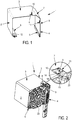
- the box 1 in sheet metal cut and folded as shown has three walls 2, 3 and 4 arranged substantially U, that is to say that the walls are of perpendicular shape in pairs.
- the free ends of the walls 2 and 4 are provided with folds or flaps 5, 6 can form slides especially used in the first phase of mounting the trunk.
- the walls 3 and 4 are further separated by an oblique face 7.
- the same walls 3, 4 have cutouts 8, 9 respectively provided with tabs 10, 11 in the form of L. Said tabs 10 and 11 are placed substantially in the center of cutouts 8 and 9, in that there is space between them and the edges delimiting said cutouts 8, 9.
- a tongue 12 is also cut in the flap 6.
- the tongue 12 is obtained by simple U-sectioning delimiting its surface, no residual cut part does not surrounding.
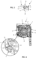
- the outer periphery of the cheek 20 conforms to the interior volume delimited by the casing 1, and comprises for this purpose three U-shaped faces perpendicular two to two, two of they are also separated by an oblique portion which slides in contact with the portion 7 of the box 1.
- Fixing the cheek 20 in the casing 1 is then performed by deformation of the tabs 10 and 11 of the cutouts 9 and 10 in the two adjacent sides 3 and 4, and on the other hand by deformation of the tongue 12 cut in the flap 6.
- the lug 10 consists of a lug 14, in this case slightly trapezoidal, and a base 15 constituting the lug that has been mentioned before (see in particular in figure 3 ) whose respective orientations are used to achieve a relative locking of the cheek 20 and the casing 1.
- a housing 18 is provided for each tab 10, 11 at the periphery of the cheek 20.
- This housing 18 can take different forms, insofar as certain characteristics are respected: thus, it must comprise opposite walls 16 facing the barrel 14 of the lug 10, in order to block the plays in the direction of the longitudinal axis of the casing 1.
- the housing 18 has a wall 17 oriented substantially parallel to said axis, which is opposite and overcomes the base 15 of the lug 10, to prevent any movement of the cheek 20 away from the wall 3 of the box 1, in particular towards the opposite side of said box 1 without a wall.
- the housing 18 must allow the rotation of the L-shaped tab during its folding around the edge 13 to orient perpendicularly to the wall 3 in which is initially cut the shape that constitutes it.
- the tab 10 is housed in recesses of the housing 18 which have the surfaces 16 and 17.
- the third fastening tab is made by cutting into a flap 6 of the sheet forming the casing 1, and it constitutes in practice a simple U-shaped cutout constituting the right tab 12, which can then be deformed in a slot 21 which protrudes from the main body of the cheek 20, is inserted into a slide 19 formed by the flap 6 in the casing 1.
- the structure of this connection appears in the enlargement placed to the left of the figure 4 .
- the tongue 12 is in practice deformed by rotation about the axis consisting of a segment 23 which connects the tongue 12 to the rest of the flap 6, deformation which leads in practice to the extraction of the tongue 12 from the wall of the flap 6 to be then inserted into said slot 21.
- a blockage in the direction of the longitudinal axis of the box 1 is formed by the tongue 12, due to the proximity and mutual orientation of the faces facing the tongue 12 and the slit 21.
- the particular shape that is given to the flap 6 during the folding of the sheet to form the slide it delimits, as well as the shape of the protrusion 22 of the cheek 20, does not only play a role. sliding guide from one into the other, but also perform a mutual blocking in other directions.
- connections according to the invention are carried out without the addition of additional materials or components (screws, rivets, etc.), and that the simple deformation of the tabs 10 to 12 around a connecting segment to the caisson 1 can easily be automated, which leads to significant time savings during the manufacture of shutter boxes and during assembly / disassembly operations.
- the cheek serves as a matrix of folding: the legs can therefore easily be folded by hand or with a simple tool such as a screwdriver.
Landscapes
- Engineering & Computer Science (AREA)
- Structural Engineering (AREA)
- Architecture (AREA)
- Civil Engineering (AREA)
- Casings For Electric Apparatus (AREA)
- Rigid Containers With Two Or More Constituent Elements (AREA)
- Drawers Of Furniture (AREA)
Abstract
L'invention concerne un coffre de volet roulant à caisson 1 central et joues 20 latérales, lesdites joues 20 étant orientées selon un plan sensiblement perpendiculaire à l'axe longitudinal du caisson 1 et encastrées dans les extrémités axiales du caisson 1, des moyens de fixation mutuels étant prévus entre eux. Ces moyens de fixation comportent une patte 10, 11, 12 par paroi 2, 3, 4 du caisson 1 obtenue par découpe dans une paroi 2, 3, 4 du caisson 1 et déformée vers l'intérieur du caisson 1 sensiblement parallèlement à l'axe longitudinal du caisson 1 en vue de coopérer avec un logement 18 débouchant dans la périphérie de la joue 20, chacun de la patte 10, 11, 12 et du logement 18 présentant en fin de déformation des faces 16 en regard orientées pour bloquer chaque joue 20 dans le caisson 1 au moins en translation dans une direction parallèle à l'axe longitudinal du caisson 1.

Description
La présente invention se situe dans le domaine des volets roulants ou similaires. Elle a plus précisément trait à la constitution des coffres de tels volets, et encore plus spécifiquement à l'assemblage de joues latérales à un caisson central, les joues et le caisson constituant ensemble le volume de rangement du volet, c'est-à-dire le coffre. Le coffre englobe le volet proprement dit lorsqu'il est enroulé, et les éléments mécaniques nécessaires à cet enroulement, au premier chef desquels se trouve l'arbre tournant qui imprime son mouvement au volet entre ses positions déployée, obturant au moins partiellement un ouvrant de bâtiment, et rangée.The present invention is in the field of shutters or the like. It relates more specifically to the constitution of the chests of such shutters, and even more specifically to the assembly of side cheeks to a central box, the cheeks and the box together constituting the storage volume of the shutter, that is to say tell the chest. The trunk includes the shutter itself when it is wound, and the mechanical elements necessary for this winding, the first of which is the rotating shaft which prints its movement to the flap between its deployed positions, closing at least partially an opening of building, and row.
De manière connue, un volet roulant comprend à cet effet un tablier, généralement guidé verticalement par l'intermédiaire de glissières latérales disposées en bordure de l'ouvrant, et dont le bord supérieur est fixé à l'arbre d'enroulement. Cet arbre est relié à l'environnement immédiat du coffre et notamment aux moyens de commandes du volet notamment via une desdites joues, qui bordent en fait latéralement la structure d'entraînement du tablier et supportent sa rotation. L'arbre est en fait maintenu libre en rotation par rapport à ces joues, et entraîné par un système manuel accessible de l'extérieur du coffre ou par un moteur d'entraînement.In known manner, a roller shutter comprises for this purpose an apron, generally guided vertically by means of side rails disposed at the edge of the leaf, and whose upper edge is fixed to the winding shaft. This shaft is connected to the immediate environment of the trunk and in particular to the control means of the flap including via one of said cheeks, which in fact border the side drive structure of the apron and support its rotation. The shaft is actually kept free to rotate relative to these cheeks, and driven by a manual system accessible from the outside of the trunk or by a drive motor.
Pour des raisons d'abord mécaniques tenant notamment aux liaisons précitées et aux guidages qu'elles impliquent, mais également pour des raisons esthétiques, le mode de fixation des joues au caisson doit faire l'objet d'une attention particulière au moment de la conception des pièces.For mechanical reasons, including the above-mentioned links and the guides they imply, but also for aesthetic reasons, the method of fixing the cheeks to the box must be the focus of attention at the time of design pieces.
Au-delà de la nécessité d'un mode de solidarisation démontable, fiable et pérenne, des enjeux industriels doivent être pris en compte autant pour la conception et la fabrication des joues et du caisson proprement dits que pour l'ensemble des opérations d'assemblage, en aval de ladite fabrication.Beyond the need for a removable, reliable and durable method of joining, industrial issues must be taken into account as much for the design and manufacture of the cheeks and the box itself as for all assembly operations , downstream of said manufacture.
A ce jour, les moyens de solidarisation des joues aux caissons que l'on peut trouver dans les configurations existantes impliquent en général des organes ou composants spécifiques de fixation, par exemple de type vis et/ou rivets. Ces moyens, certes d'usage universel et faciles à mettre en oeuvre, sont cependant souvent employés au détriment de la précision d'assemblage, et ils conduisent à des opérations manuelles de fixation des joues aux caissons qui prennent du temps. Ce caractère manuel se retrouve évidemment ensuite lors de toutes les opérations de démontage/remontage.To date, the means for securing the cheeks to the boxes that can be found in the existing configurations generally involve specific fastening members or components, for example of the screw and / or rivet type. These means, certainly universal and easy to implement, however, are often used at the expense of assembly accuracy, and they lead to manual operations of fixing the cheeks to the boxes that take time. This manual character is obviously found later in all disassembly / reassembly operations.
Il se traduit par une durée d'intervention non négligeable, qui dépend d'ailleurs notamment du nombre d'organes de fixation employés, d'où une tendance à en utiliser un nombre minimal pouvant entraîner le manque de précision dont il a été fait état auparavant.It results in a non-negligible duration of intervention, which also depends in particular on the number of fasteners used, hence a tendency to use a minimal number that may cause the lack of precision that has been reported. before.
Par ailleurs, ce type de solution n'est en général pas automatisée et en tout état de cause pas facilement automatisable, et elle occupe dès lors au moins un opérateur à chaque opération de montage/démontage. La durée totale des opérations, et la nécessité d'y assigner du temps de travail affectable à au moins un opérateur, rendent ce genre d'installations peu attractif sur un plan strictement économique.Moreover, this type of solution is generally not automated and in any case not easily automated, and it therefore occupies at least one operator for each assembly / disassembly operation. The total duration of operations, and the need to assign assignable working time to at least one operator, make this type of facility unattractive on a strictly economic basis.
La présente invention remédie à ce constat, en proposant une solution aisément automatisable, donc dépourvue autant que possible d'intervention humaine, fonctionnant de surcroît sans pièces de montage additionnelles extérieures au système. La solution proposée est en outre rapide à implémenter, et elle permet d'aboutir à un résultat final d'une grande précision auquel on peut conférer des caractéristiques esthétiques très abouties.The present invention overcomes this finding, by proposing an easily automated solution, thus devoid as much as possible of human intervention, in addition operating without additional mounting parts external to the system. The proposed solution is also quick to implement, and it leads to a final result of great precision to which we can confer very successful aesthetic characteristics.
Pour remplir ces objectifs, et d'autres qui apparaîtront dans la suite, l'invention, qui concerne en pratique un coffre de volet roulant à caisson central et joues latérales, lesdites joues étant orientées selon un plan sensiblement perpendiculaire à l'axe longitudinal du caisson et encastrées dans les extrémités axiales du caisson, des moyens de fixation mutuels étant prévus entre eux, est telle que ces moyens de fixation comportent une patte par paroi du caisson, obtenue par découpe dans une paroi du caisson et déformée vers l'intérieur du caisson sensiblement parallèlement à l'axe longitudinal du caisson en vue de coopérer avec un logement débouchant dans la périphérie de la joue, chacun de la patte et du logement présentant en fin de déformation des faces en regard orientées pour bloquer chaque joue dans le caisson au moins en translation dans une direction parallèle à l'axe longitudinal du caisson.To fulfill these objectives, and others which will appear in the following, the invention, which relates in practice to a roller shutter box with central box and side cheeks, said cheeks being oriented in a plane substantially perpendicular to the longitudinal axis of the box and recessed in the axial ends of the box, mutual fixing means being provided between them, is such that these fixing means comprise a tab by wall of the box, obtained by cutting into a wall of the box and deformed towards the inside of the caisson substantially parallel to the longitudinal axis of the box in order to cooperate with a housing opening into the periphery of the cheek, each of the tab and the housing having at the end of deformation facing faces oriented to block each cheek in the box at less in translation in a direction parallel to the longitudinal axis of the box.
Un avantage immédiat d'une telle configuration est d'ordre pratique, puisqu'elle permet d'accroître sensiblement la rapidité de mise en oeuvre et la précision du montage. Secondairement, il n'y a plus lieu de se préoccuper de sélectionner les pièces adaptées pour réaliser la fixation, et il n'y a plus non plus de risques de perte des matériels/composants en question, susceptibles d'occasionner des pertes de temps fâcheuses.An immediate advantage of such a configuration is of a practical nature, since it makes it possible to substantially increase the speed of implementation and the precision of the assembly. Secondarily, there is no need to worry about selecting the appropriate parts to achieve the fixation, and there is also no risk of loss of materials / components in question, may cause loss of time adverse.
La simple existence de pattes à déformer permet aussi, si elle est souhaitée, la mise en oeuvre d'une automatisation qui nécessite dans un premier temps un positionnement relatif des joues et du caisson et dans un second temps la déformation des pattes en vue du blocage des joues dans le caisson, opérations relativement aisées à automatiser.The mere existence of legs to deform also allows, if desired, the implementation of a automation which initially requires a relative positioning of the cheeks and the box and in a second time the deformation of the legs to block the cheeks in the box, relatively easy operations to automate.
Plus précisément, la jonction d'une patte découpée avec le caisson formant de fait un segment rectiligne, ledit segment est orienté sensiblement parallèlement à l'axe longitudinal du caisson, selon l'invention, et la déformation de la patte s'effectue ensuite par rotation autour de ce segment.More specifically, the junction of a cut tab with the box forming a rectilinear segment, said segment is oriented substantially parallel to the longitudinal axis of the box, according to the invention, and the deformation of the tab is then effected by rotation around this segment.
Il s'agit donc d'un type de déformation tout à fait élémentaire, qui contribue à la simplicité d'implémentation soulignée auparavant, et permet in fine de mettre en oeuvre une automatisation des opérations de montage/démontage.It is therefore a type of quite basic deformation, which contributes to simplicity of implementation highlighted before, and ultimately allows to implement an automation of assembly / disassembly operations.
En pratique, deux chants d'au moins certaines des pattes issues des extrémités du segment de jonction présentent une convergence conférant une forme trapézoïdale à au moins une portion de ladite patte d'axe d'allure perpendiculaire à l'axe longitudinal du caisson, cette orientation permettant de réaliser un blocage longitudinal des joues. La forme trapézoïdale autorise un centrage progressif à mesure du pliage et elle garantit une meilleure maîtrise de la position finale sans nécessiter une mise en position trop précise avant pliage. Alternativement, lesdits chants peuvent être prévus parallèles et d'allure perpendiculaire à l'axe longitudinal du caisson.In practice, two edges of at least some of the tabs coming from the ends of the joining segment have a conferring conferring a trapezoidal shape on at least a portion of said tab of axis of shape perpendicular to the longitudinal axis of the box, this orientation to achieve a longitudinal blocking of the cheeks. The trapezoidal shape allows progressive centering as bending takes place and ensures better control of the end position without the need for too precise positioning before folding. Alternatively, said edges may be provided parallel and perpendicular to the longitudinal axis of the box.
Pour réaliser pleinement une fonction de fixation qui n'est pas limitée à une direction d'allure parallèle à l'axe longitudinal du caisson, la patte peut être en forme de L, comportant donc un ergot terminal s'insérant dans un évidement présentant au moins une paroi en regard dudit ergot d'allure parallèle à l'axe longitudinal du caisson et située entre l'ergot et la périphérie de la joue.To achieve fully a fastening function which is not limited to a direction parallel to the longitudinal axis of the box, the tab can be L-shaped, thus having a terminal pin inserting in a recess having at least one wall facing said lug parallel to the longitudinal axis of the box and located between the lug and the periphery of the cheek.
Cet ergot permet en fait un verrouillage dans une direction perpendiculaire à la précédente, dont l'orientation est plutôt d'allure radiale. Il empêche le caisson, dont on verra dans la suite qu'il ne comporte pas nécessairement de cloisons sur toute sa périphérie, d'être décollé d'une paroi par exemple lorsqu'il est sollicité en direction d'une partie de la périphérie dépourvue de cloison. Plus généralement, cette caractéristique de fixation supplémentaire vise à assurer un blocage complet dans au moins deux directions.This lug actually allows locking in a direction perpendicular to the previous, whose orientation is rather radial. It prevents the box, which will be seen in the following that it does not necessarily have partitions over its entire periphery, to be peeled off a wall for example when it is biased towards a part of the periphery without of partition. More generally, this additional fastening feature aims to ensure complete locking in at least two directions.
Cela étant, les pattes peuvent aussi être plus simples, selon la nature, la géométrie et éventuellement le positionnement des logements prévus dans le pourtour des joues, comme on le verra dans la suite.However, the legs can also be simpler, depending on the nature, geometry and possibly the positioning of the housing provided in the periphery of the cheeks, as will be seen later.
Ainsi, selon une configuration possible, évoquée ci-dessus, le caisson peut être prismatique et comporter trois parois principales perpendiculaires deux à deux pour constituer une section globalement en U. Une telle forme s'explique notamment par le fait que la paroi manquante pour clore le volume est occupée par une trappe de visite.Thus, in a possible configuration, mentioned above, the box may be prismatic and have three main walls perpendicular two by two to form a generally U-shaped section. Such a shape is explained in particular by the fact that the missing wall to close the volume is occupied by a trap door.
Dans ce cas, les extrémités libres des parois parallèles peuvent comporter des replis ou rabats vers l'intérieur, formant glissières qui peuvent servir au guidage des joues dans le volume intérieur délimité par les parois du caisson. Ce guidage peut notamment intervenir au moment de l'encastrement initial visant à positionner chaque joue dans le volume du caisson, à proximité de ses extrémités axiales.In this case, the free ends of the parallel walls may comprise folds or flaps inward, forming slides which can be used for guiding the cheeks in the interior volume delimited by the walls of the box. This guidance may in particular occur at the time of the initial embedding to position each cheek in the volume of the box, near its axial ends.
Selon une possibilité propre à l'invention, et qui reflète la configuration particulière des caissons présentant la particularité géométrique mentionnée ci-dessus, les pattes sont au nombre de trois, localisées dans deux parois et un repli dudit caisson.According to a possibility specific to the invention, and which reflects the particular configuration of the boxes having the geometric feature mentioned above, the legs are three in number, located in two walls and a fold of said box.
En pratique, deux pattes découpées peuvent être en forme de L à fût trapézoïdal dont la base forme l'ergot précité, la troisième patte, placée dans un repli en glissière, pouvant prendre la forme d'une languette droite. Dans ce dernier cas, l'insertion dans une fente du caisson, en l'occurrence dans une fente du repli ou rabat, vise à empêcher un déplacement relatif dans le sens axial du caisson, mais n'a pas d'effet dans d'autres directions pour lesquelles ce sont des formes particulières du caisson et de la joue qui réalisent les blocages, s'il y a lieu.In practice, two cut tabs can be L-shaped trapezoidal shaft whose base forms the aforementioned pin, the third leg, placed in a folded slide, which can take the form of a straight tab. In the latter case, the insertion in a slot of the box, in this case in a slot of the fold or flap, is intended to prevent a relative displacement in the axial direction of the box, but has no effect in other directions for which it is particular forms of the box and the cheek that realize the blockages, if it is necessary.
Toutes ces caractéristiques permettent de réaliser une fixation rapide et précise des joues dans un caisson central, aboutissant à réaliser un coffre de volet roulant à l'esthétique extérieure irréprochable, et dont le montage/démontage est aisé et immédiat du fait des choix technologiques effectués.All these features make it possible to achieve a fast and precise attachment of the cheeks in a central box, resulting in a roller shutter box with an impeccable exterior aesthetic, and whose assembly / disassembly is easy and immediate because of the technological choices made.
L'invention va à présent être décrite plus en détail, en référence aux figures annexées qui représentent un exemple de mise en oeuvre non limitatif de l'invention, et pour lesquelles :
- la
figure 1 représente en perspective une portion d'un caisson de coffre selon l'invention ; - la
figure 2 montre, également en vue perspective, ladite portion, dans l'extrémité libre de laquelle une joue est montée, un détail agrandi d'une zone de fixation selon un premier mode de fixation étant représenté ; - la
figure 3 montre la même zone de fixation selon une vue de face ; et - la
figure 4 représente une vue perspective selon un angle différent de celle de lafigure 2 , montrant plus clairement une autre zone de fixation avec un second mode de fixation, un détail agrandi de ce second mode de fixation étant également montré.
- the
figure 1 represents in perspective a portion of a trunk box according to the invention; - the
figure 2 shows, also in perspective view, said portion, in the free end of which a cheek is mounted, an enlarged detail of a fastening zone according to a first fastening mode being shown; - the
figure 3 shows the same fixing area according to a front view; and - the
figure 4 represents a perspective view at an angle different from that of thefigure 2 , showing more clearly another attachment zone with a second mode of attachment, an enlarged detail of this second mode of attachment being also shown.
En référence à la
Une languette 12 est par ailleurs découpée dans le rabat 6. A l'inverse de la configuration utilisée pour les pattes 10, 11 en L, la languette 12 est obtenue par simple sectionnement en U délimitant sa surface, aucune partie découpée résiduelle ne l'entourant.A
Lorsqu'une joue 20, réalisée par exemple par moulage plastique et dotée de rainures/nervures notamment de rigidification, est insérée dans le caisson 1 comme illustré par exemple en
La fixation de la joue 20 dans le caisson 1 s'effectue ensuite par déformation d'une part des pattes 10 et 11 des découpes 9 et 10 dans les deux côtés adjacents 3 et 4, et d'autre part par déformation de la languette 12 découpée dans le rabat 6.Fixing the
Le principe de la fixation est expliqué plus clairement, pour les pattes 10 et 11 en L, en référence simultanément à l'agrandissement situé à droite de la
Un logement 18 est prévu pour chaque patte 10, 11 en périphérie de la joue 20. La description qui suit s'applique plus particulièrement à la patte 10, seule visible sur les
La troisième patte de fixation, dénommée languette 12, est réalisée par découpe dans un rabat 6 de la tôle formant le caisson 1, et elle constitue en pratique une simple découpe en U constituant la languette droite 12, laquelle peut ensuite être déformée dans une fente 21 d'une protubérance 22 de la joue 20. Celle-ci, qui dépasse du corps principal de la joue 20, est insérée dans une glissière 19 formée par le rabat 6 dans le caisson 1. La structure de cette liaison apparaît dans l'agrandissement placé à gauche de la
La languette 12 est en pratique déformée par rotation autour de l'axe constitué par un segment 23 qui relie la languette 12 au reste du rabat 6, déformation qui aboutit en pratique à l'extraction de la languette 12 hors de la paroi du rabat 6 pour être ensuite insérée dans ladite fente 21. Un blocage dans la direction de l'axe longitudinal du caisson 1 est réalisé par la languette 12, du fait de la proximité et de l'orientation mutuelle des faces en regard de la languette 12 et de la fente 21. Il est par ailleurs à noter que la forme particulière qui est donnée au rabat 6 lors du repli de la tôle pour constituer la glissière qu'il délimite, ainsi que la forme de la protubérance 22 de la joue 20, ne jouent pas qu'un rôle de guidage en coulissement de l'un dans l'autre, mais réalisent aussi un blocage mutuel dans d'autres directions.The
La coopération des pattes en L 10, 11 et des logements 18 d'une part, celle de la languette 12 avec la fente 21 combinée aux formes relatives du rabat 6 et de la protubérance 22 d'autre part, contribuent à un blocage efficace de chaque joue 20 dans le caisson 1. Ces moyens de liaison permettent également de réaliser un positionnement précis de l'un dans l'autre, aboutissant à une apparence irréprochable du coffre de volet roulant notamment parce que l'aspect extérieur du coffre est largement tributaire du caisson, dont la forme résulte d'opérations bien maîtrisées de découpage / pliage / emboutissage. Enfin, le mode de fixation par languette mis en oeuvre dans le cadre de l'invention permet d'aboutir à une solution invisible : l'implantation de la languette 12 dans le rabat 6 n'est pas visible de l'extérieur, et les languettes 10, 11 des faces 3 et 4 ne sont pas non plus visibles lorsque le coffre est installé.The cooperation of the L-shaped
On constate bien que les liaisons selon l'invention s'effectuent sans apport de matériels ou composants (vis, rivets..) supplémentaires, et que la simple déformation des pattes 10 à 12 autour d'un segment de liaison au caisson 1 peut aisément être automatisée, ce qui conduit à des gains temporels conséquents au cours de la fabrication des coffres de volets roulants ainsi qu'au cours des opérations de montage / démontage. Il est à noter que lors du pliage des pattes, la joue sert de matrice de pliage : les pattes peuvent donc aussi très facilement être pliées à la main ou avec un simple outil tel qu'un tournevis.It can be seen that the connections according to the invention are carried out without the addition of additional materials or components (screws, rivets, etc.), and that the simple deformation of the
L'invention ne se limite bien entendu pas à l'exemple décrit et expliqué en référence aux figures, qui ne doit être considéré que comme une simple illustration de l'invention. Elle englobe au contraire les variantes et versions qui entrent dans la portée des revendications, incluant par exemple les variations de forme et de positionnement des pattes 10 à 12, des découpes 8 et 9, des logements 18, etc. Pour réaliser les conditions techniques des liaisons montrées, une grande variété de formes est possible, à condition de respecter certaines contraintes essentielles qui ont été soulignées auparavant.The invention is of course not limited to the example described and explained with reference to the figures, which should be considered as a mere illustration of the invention. On the contrary, it encompasses the variants and versions that come within the scope of the claims, including, for example, variations in shape and positioning of the
Claims (9)
Priority Applications (1)
| Application Number | Priority Date | Filing Date | Title |
|---|---|---|---|
| PL18166001T PL3385491T3 (en) | 2017-04-07 | 2018-04-06 | Roller shutter box |
Applications Claiming Priority (1)
| Application Number | Priority Date | Filing Date | Title |
|---|---|---|---|
| FR1753037A FR3064929A1 (en) | 2017-04-07 | 2017-04-07 | ROOF SHUTTER BOX WITH HOUSING. |
Publications (2)
| Publication Number | Publication Date |
|---|---|
| EP3385491A1 true EP3385491A1 (en) | 2018-10-10 |
| EP3385491B1 EP3385491B1 (en) | 2020-06-03 |
Family
ID=59325416
Family Applications (1)
| Application Number | Title | Priority Date | Filing Date |
|---|---|---|---|
| EP18166001.0A Active EP3385491B1 (en) | 2017-04-07 | 2018-04-06 | Roller shutter box |
Country Status (4)
| Country | Link |
|---|---|
| EP (1) | EP3385491B1 (en) |
| ES (1) | ES2811023T3 (en) |
| FR (1) | FR3064929A1 (en) |
| PL (1) | PL3385491T3 (en) |
Cited By (1)
| Publication number | Priority date | Publication date | Assignee | Title |
|---|---|---|---|---|
| FR3120383A1 (en) | 2021-03-02 | 2022-09-09 | Zurfluh Feller | Protective box, in particular for roller shutter, assembly sub-assembly, protective installation comprising such a box and method of assembling such a box |
Citations (2)
| Publication number | Priority date | Publication date | Assignee | Title |
|---|---|---|---|---|
| DE7046128U (en) * | Fa P Knoll | Shutter box | ||
| DE19738333A1 (en) * | 1997-09-02 | 1999-03-04 | Guenter Dipl Ing Lenze | Curtain cassette with cassette profile |
-
2017
- 2017-04-07 FR FR1753037A patent/FR3064929A1/en active Pending
-
2018
- 2018-04-06 ES ES18166001T patent/ES2811023T3/en active Active
- 2018-04-06 PL PL18166001T patent/PL3385491T3/en unknown
- 2018-04-06 EP EP18166001.0A patent/EP3385491B1/en active Active
Patent Citations (2)
| Publication number | Priority date | Publication date | Assignee | Title |
|---|---|---|---|---|
| DE7046128U (en) * | Fa P Knoll | Shutter box | ||
| DE19738333A1 (en) * | 1997-09-02 | 1999-03-04 | Guenter Dipl Ing Lenze | Curtain cassette with cassette profile |
Cited By (1)
| Publication number | Priority date | Publication date | Assignee | Title |
|---|---|---|---|---|
| FR3120383A1 (en) | 2021-03-02 | 2022-09-09 | Zurfluh Feller | Protective box, in particular for roller shutter, assembly sub-assembly, protective installation comprising such a box and method of assembling such a box |
Also Published As
| Publication number | Publication date |
|---|---|
| ES2811023T3 (en) | 2021-03-10 |
| FR3064929A1 (en) | 2018-10-12 |
| EP3385491B1 (en) | 2020-06-03 |
| PL3385491T3 (en) | 2020-11-16 |
Similar Documents
| Publication | Publication Date | Title |
|---|---|---|
| EP2729651B1 (en) | Coupling and home installation with such a coupling | |
| EP0053543A2 (en) | Devices for fixing objects to sheet metals accessible from one side only | |
| EP3425143B1 (en) | Latch for enclosure barrier lock | |
| EP3756501A1 (en) | Fixing device for a bracelet | |
| FR3001006A1 (en) | ARTICLE TO BE FIXED IN A BLIND ON A SUPPORT | |
| FR2966649A1 (en) | CONNECTOR WITH COMMITMENT ON | |
| EP3385491B1 (en) | Roller shutter box | |
| EP2816241A1 (en) | Connection device for assembling two profiles | |
| EP2068409B1 (en) | Corner accessory for gutters with swinging flaps | |
| FR2967229A1 (en) | DEVICE FOR SECURELY CONNECTING TWO BITS, IN PARTICULAR A PIPE. | |
| EP2648939B1 (en) | Conduit for receiving elongate elements, method for mounting same, and assembly comprising a mounting and such a conduit | |
| EP3346306B1 (en) | Detachable connection device for a light guide and application in a motor vehicle, optical transmission module fitted with the device | |
| FR2553590A1 (en) | CARBON BRUSH ASSEMBLY | |
| EP3293344B1 (en) | Device for unwinding/winding a roller shutter | |
| EP1930606A1 (en) | System for assembling two parts with the help of a device with a hook and an assembly element | |
| FR2809761A1 (en) | DEVICE FORMING END SUPPORT FOR A WINDING SHAFT, ITS ASSEMBLY METHOD AND HANDLING MECHANISM OF A CLOSURE OR SOLAR PROTECTION SYSTEM COMPRISING SUCH A DEVICE | |
| CH693218A5 (en) | Lock fitting with sash for fixing inner support means and staggered outside and opening with a fitting such. | |
| FR2998608A1 (en) | Roller shutter for installation in opening of building, has external support area converging towards internal support area to tilt side sections relative to legs when free end of legs is engaged between internal walls of tubular part | |
| FR2979126A1 (en) | ROTATION DRIVE DEVICE, ESPECIALLY A HEAT ENGINE STARTER AND METHOD FOR CARRYING OUT SAID METHOD | |
| EP1717459A1 (en) | Device for fixing a member to a panel comprising an assembly made out of a cage and an insert and method for manufacturing said assembly | |
| FR2470399A1 (en) | CAMERA SHUTTER | |
| EP3059376A1 (en) | Assembly method for closure or solar protection installation, support system and installation | |
| FR3001486A1 (en) | Lock system, has driving unit for driving rotor by key and including boss projecting from shoulder around guide in inlet direction and slot at end of key, where boss and slot are co-operated together to pivotingly drive rotor | |
| FR2919657A1 (en) | Operating unit e.g. electric tubular actuator, assembling device for e.g. roller shutter type screen, has piece mounted on another piece by translatory movement parallel to opening's central axes parallel to central axis of pin | |
| FR3142925A1 (en) | Screwing guide for fixing a component of a motor vehicle |
Legal Events
| Date | Code | Title | Description |
|---|---|---|---|
| PUAI | Public reference made under article 153(3) epc to a published international application that has entered the european phase |
Free format text: ORIGINAL CODE: 0009012 |
|
| STAA | Information on the status of an ep patent application or granted ep patent |
Free format text: STATUS: THE APPLICATION HAS BEEN PUBLISHED |
|
| AK | Designated contracting states |
Kind code of ref document: A1 Designated state(s): AL AT BE BG CH CY CZ DE DK EE ES FI FR GB GR HR HU IE IS IT LI LT LU LV MC MK MT NL NO PL PT RO RS SE SI SK SM TR |
|
| AX | Request for extension of the european patent |
Extension state: BA ME |
|
| STAA | Information on the status of an ep patent application or granted ep patent |
Free format text: STATUS: REQUEST FOR EXAMINATION WAS MADE |
|
| 17P | Request for examination filed |
Effective date: 20190306 |
|
| RBV | Designated contracting states (corrected) |
Designated state(s): AL AT BE BG CH CY CZ DE DK EE ES FI FR GB GR HR HU IE IS IT LI LT LU LV MC MK MT NL NO PL PT RO RS SE SI SK SM TR |
|
| GRAP | Despatch of communication of intention to grant a patent |
Free format text: ORIGINAL CODE: EPIDOSNIGR1 |
|
| STAA | Information on the status of an ep patent application or granted ep patent |
Free format text: STATUS: GRANT OF PATENT IS INTENDED |
|
| INTG | Intention to grant announced |
Effective date: 20191211 |
|
| RIN1 | Information on inventor provided before grant (corrected) |
Inventor name: DROUET, SEBASTIEN |
|
| GRAS | Grant fee paid |
Free format text: ORIGINAL CODE: EPIDOSNIGR3 |
|
| RAP1 | Party data changed (applicant data changed or rights of an application transferred) |
Owner name: BUBENDORFF SA |
|
| GRAA | (expected) grant |
Free format text: ORIGINAL CODE: 0009210 |
|
| STAA | Information on the status of an ep patent application or granted ep patent |
Free format text: STATUS: THE PATENT HAS BEEN GRANTED |
|
| AK | Designated contracting states |
Kind code of ref document: B1 Designated state(s): AL AT BE BG CH CY CZ DE DK EE ES FI FR GB GR HR HU IE IS IT LI LT LU LV MC MK MT NL NO PL PT RO RS SE SI SK SM TR |
|
| REG | Reference to a national code |
Ref country code: GB Ref legal event code: FG4D Free format text: NOT ENGLISH |
|
| REG | Reference to a national code |
Ref country code: CH Ref legal event code: EP Ref country code: AT Ref legal event code: REF Ref document number: 1277188 Country of ref document: AT Kind code of ref document: T Effective date: 20200615 |
|
| REG | Reference to a national code |
Ref country code: DE Ref legal event code: R096 Ref document number: 602018004978 Country of ref document: DE |
|
| RAP2 | Party data changed (patent owner data changed or rights of a patent transferred) |
Owner name: BHG |
|
| REG | Reference to a national code |
Ref country code: LT Ref legal event code: MG4D |
|
| PG25 | Lapsed in a contracting state [announced via postgrant information from national office to epo] |
Ref country code: LT Free format text: LAPSE BECAUSE OF FAILURE TO SUBMIT A TRANSLATION OF THE DESCRIPTION OR TO PAY THE FEE WITHIN THE PRESCRIBED TIME-LIMIT Effective date: 20200603 Ref country code: SE Free format text: LAPSE BECAUSE OF FAILURE TO SUBMIT A TRANSLATION OF THE DESCRIPTION OR TO PAY THE FEE WITHIN THE PRESCRIBED TIME-LIMIT Effective date: 20200603 Ref country code: FI Free format text: LAPSE BECAUSE OF FAILURE TO SUBMIT A TRANSLATION OF THE DESCRIPTION OR TO PAY THE FEE WITHIN THE PRESCRIBED TIME-LIMIT Effective date: 20200603 Ref country code: NO Free format text: LAPSE BECAUSE OF FAILURE TO SUBMIT A TRANSLATION OF THE DESCRIPTION OR TO PAY THE FEE WITHIN THE PRESCRIBED TIME-LIMIT Effective date: 20200903 Ref country code: GR Free format text: LAPSE BECAUSE OF FAILURE TO SUBMIT A TRANSLATION OF THE DESCRIPTION OR TO PAY THE FEE WITHIN THE PRESCRIBED TIME-LIMIT Effective date: 20200904 |
|
| REG | Reference to a national code |
Ref country code: NL Ref legal event code: MP Effective date: 20200603 |
|
| PG25 | Lapsed in a contracting state [announced via postgrant information from national office to epo] |
Ref country code: LV Free format text: LAPSE BECAUSE OF FAILURE TO SUBMIT A TRANSLATION OF THE DESCRIPTION OR TO PAY THE FEE WITHIN THE PRESCRIBED TIME-LIMIT Effective date: 20200603 Ref country code: BG Free format text: LAPSE BECAUSE OF FAILURE TO SUBMIT A TRANSLATION OF THE DESCRIPTION OR TO PAY THE FEE WITHIN THE PRESCRIBED TIME-LIMIT Effective date: 20200903 Ref country code: RS Free format text: LAPSE BECAUSE OF FAILURE TO SUBMIT A TRANSLATION OF THE DESCRIPTION OR TO PAY THE FEE WITHIN THE PRESCRIBED TIME-LIMIT Effective date: 20200603 Ref country code: HR Free format text: LAPSE BECAUSE OF FAILURE TO SUBMIT A TRANSLATION OF THE DESCRIPTION OR TO PAY THE FEE WITHIN THE PRESCRIBED TIME-LIMIT Effective date: 20200603 |
|
| REG | Reference to a national code |
Ref country code: AT Ref legal event code: MK05 Ref document number: 1277188 Country of ref document: AT Kind code of ref document: T Effective date: 20200603 |
|
| PG25 | Lapsed in a contracting state [announced via postgrant information from national office to epo] |
Ref country code: NL Free format text: LAPSE BECAUSE OF FAILURE TO SUBMIT A TRANSLATION OF THE DESCRIPTION OR TO PAY THE FEE WITHIN THE PRESCRIBED TIME-LIMIT Effective date: 20200603 Ref country code: AL Free format text: LAPSE BECAUSE OF FAILURE TO SUBMIT A TRANSLATION OF THE DESCRIPTION OR TO PAY THE FEE WITHIN THE PRESCRIBED TIME-LIMIT Effective date: 20200603 |
|
| PG25 | Lapsed in a contracting state [announced via postgrant information from national office to epo] |
Ref country code: RO Free format text: LAPSE BECAUSE OF FAILURE TO SUBMIT A TRANSLATION OF THE DESCRIPTION OR TO PAY THE FEE WITHIN THE PRESCRIBED TIME-LIMIT Effective date: 20200603 Ref country code: CZ Free format text: LAPSE BECAUSE OF FAILURE TO SUBMIT A TRANSLATION OF THE DESCRIPTION OR TO PAY THE FEE WITHIN THE PRESCRIBED TIME-LIMIT Effective date: 20200603 Ref country code: PT Free format text: LAPSE BECAUSE OF FAILURE TO SUBMIT A TRANSLATION OF THE DESCRIPTION OR TO PAY THE FEE WITHIN THE PRESCRIBED TIME-LIMIT Effective date: 20201006 Ref country code: AT Free format text: LAPSE BECAUSE OF FAILURE TO SUBMIT A TRANSLATION OF THE DESCRIPTION OR TO PAY THE FEE WITHIN THE PRESCRIBED TIME-LIMIT Effective date: 20200603 Ref country code: EE Free format text: LAPSE BECAUSE OF FAILURE TO SUBMIT A TRANSLATION OF THE DESCRIPTION OR TO PAY THE FEE WITHIN THE PRESCRIBED TIME-LIMIT Effective date: 20200603 Ref country code: SM Free format text: LAPSE BECAUSE OF FAILURE TO SUBMIT A TRANSLATION OF THE DESCRIPTION OR TO PAY THE FEE WITHIN THE PRESCRIBED TIME-LIMIT Effective date: 20200603 |
|
| PG25 | Lapsed in a contracting state [announced via postgrant information from national office to epo] |
Ref country code: SK Free format text: LAPSE BECAUSE OF FAILURE TO SUBMIT A TRANSLATION OF THE DESCRIPTION OR TO PAY THE FEE WITHIN THE PRESCRIBED TIME-LIMIT Effective date: 20200603 Ref country code: IS Free format text: LAPSE BECAUSE OF FAILURE TO SUBMIT A TRANSLATION OF THE DESCRIPTION OR TO PAY THE FEE WITHIN THE PRESCRIBED TIME-LIMIT Effective date: 20201003 |
|
| REG | Reference to a national code |
Ref country code: DE Ref legal event code: R097 Ref document number: 602018004978 Country of ref document: DE |
|
| REG | Reference to a national code |
Ref country code: ES Ref legal event code: FG2A Ref document number: 2811023 Country of ref document: ES Kind code of ref document: T3 Effective date: 20210310 |
|
| PLBE | No opposition filed within time limit |
Free format text: ORIGINAL CODE: 0009261 |
|
| STAA | Information on the status of an ep patent application or granted ep patent |
Free format text: STATUS: NO OPPOSITION FILED WITHIN TIME LIMIT |
|
| PG25 | Lapsed in a contracting state [announced via postgrant information from national office to epo] |
Ref country code: DK Free format text: LAPSE BECAUSE OF FAILURE TO SUBMIT A TRANSLATION OF THE DESCRIPTION OR TO PAY THE FEE WITHIN THE PRESCRIBED TIME-LIMIT Effective date: 20200603 |
|
| 26N | No opposition filed |
Effective date: 20210304 |
|
| PG25 | Lapsed in a contracting state [announced via postgrant information from national office to epo] |
Ref country code: SI Free format text: LAPSE BECAUSE OF FAILURE TO SUBMIT A TRANSLATION OF THE DESCRIPTION OR TO PAY THE FEE WITHIN THE PRESCRIBED TIME-LIMIT Effective date: 20200603 |
|
| PG25 | Lapsed in a contracting state [announced via postgrant information from national office to epo] |
Ref country code: MC Free format text: LAPSE BECAUSE OF FAILURE TO SUBMIT A TRANSLATION OF THE DESCRIPTION OR TO PAY THE FEE WITHIN THE PRESCRIBED TIME-LIMIT Effective date: 20200603 |
|
| PG25 | Lapsed in a contracting state [announced via postgrant information from national office to epo] |
Ref country code: LU Free format text: LAPSE BECAUSE OF NON-PAYMENT OF DUE FEES Effective date: 20210406 |
|
| REG | Reference to a national code |
Ref country code: BE Ref legal event code: MM Effective date: 20210430 |
|
| PG25 | Lapsed in a contracting state [announced via postgrant information from national office to epo] |
Ref country code: CH Free format text: LAPSE BECAUSE OF NON-PAYMENT OF DUE FEES Effective date: 20210430 Ref country code: LI Free format text: LAPSE BECAUSE OF NON-PAYMENT OF DUE FEES Effective date: 20210430 |
|
| PG25 | Lapsed in a contracting state [announced via postgrant information from national office to epo] |
Ref country code: IE Free format text: LAPSE BECAUSE OF NON-PAYMENT OF DUE FEES Effective date: 20210406 |
|
| PG25 | Lapsed in a contracting state [announced via postgrant information from national office to epo] |
Ref country code: IS Free format text: LAPSE BECAUSE OF FAILURE TO SUBMIT A TRANSLATION OF THE DESCRIPTION OR TO PAY THE FEE WITHIN THE PRESCRIBED TIME-LIMIT Effective date: 20201003 |
|
| PG25 | Lapsed in a contracting state [announced via postgrant information from national office to epo] |
Ref country code: BE Free format text: LAPSE BECAUSE OF NON-PAYMENT OF DUE FEES Effective date: 20210430 |
|
| GBPC | Gb: european patent ceased through non-payment of renewal fee |
Effective date: 20220406 |
|
| PG25 | Lapsed in a contracting state [announced via postgrant information from national office to epo] |
Ref country code: GB Free format text: LAPSE BECAUSE OF NON-PAYMENT OF DUE FEES Effective date: 20220406 |
|
| PG25 | Lapsed in a contracting state [announced via postgrant information from national office to epo] |
Ref country code: CY Free format text: LAPSE BECAUSE OF FAILURE TO SUBMIT A TRANSLATION OF THE DESCRIPTION OR TO PAY THE FEE WITHIN THE PRESCRIBED TIME-LIMIT Effective date: 20200603 |
|
| PG25 | Lapsed in a contracting state [announced via postgrant information from national office to epo] |
Ref country code: HU Free format text: LAPSE BECAUSE OF FAILURE TO SUBMIT A TRANSLATION OF THE DESCRIPTION OR TO PAY THE FEE WITHIN THE PRESCRIBED TIME-LIMIT; INVALID AB INITIO Effective date: 20180406 |
|
| PG25 | Lapsed in a contracting state [announced via postgrant information from national office to epo] |
Ref country code: MK Free format text: LAPSE BECAUSE OF FAILURE TO SUBMIT A TRANSLATION OF THE DESCRIPTION OR TO PAY THE FEE WITHIN THE PRESCRIBED TIME-LIMIT Effective date: 20200603 |
|
| PGFP | Annual fee paid to national office [announced via postgrant information from national office to epo] |
Ref country code: PL Payment date: 20240325 Year of fee payment: 7 |
|
| PGFP | Annual fee paid to national office [announced via postgrant information from national office to epo] |
Ref country code: DE Payment date: 20240530 Year of fee payment: 7 |
|
| PGFP | Annual fee paid to national office [announced via postgrant information from national office to epo] |
Ref country code: ES Payment date: 20240617 Year of fee payment: 7 |
|
| PGFP | Annual fee paid to national office [announced via postgrant information from national office to epo] |
Ref country code: IT Payment date: 20240426 Year of fee payment: 7 Ref country code: FR Payment date: 20240422 Year of fee payment: 7 |
|
| PG25 | Lapsed in a contracting state [announced via postgrant information from national office to epo] |
Ref country code: MT Free format text: LAPSE BECAUSE OF FAILURE TO SUBMIT A TRANSLATION OF THE DESCRIPTION OR TO PAY THE FEE WITHIN THE PRESCRIBED TIME-LIMIT Effective date: 20200603 |