EP3385490A1 - Screening body with improved weather resistance, uv restistance and lamination properties - Google Patents
Screening body with improved weather resistance, uv restistance and lamination properties Download PDFInfo
- Publication number
- EP3385490A1 EP3385490A1 EP18163303.3A EP18163303A EP3385490A1 EP 3385490 A1 EP3385490 A1 EP 3385490A1 EP 18163303 A EP18163303 A EP 18163303A EP 3385490 A1 EP3385490 A1 EP 3385490A1
- Authority
- EP
- European Patent Office
- Prior art keywords
- fabric
- screening
- layer
- screening body
- adhesive
- Prior art date
- Legal status (The legal status is an assumption and is not a legal conclusion. Google has not performed a legal analysis and makes no representation as to the accuracy of the status listed.)
- Granted
Links
- 238000012216 screening Methods 0.000 title claims abstract description 100
- 238000003475 lamination Methods 0.000 title claims description 6
- 239000004744 fabric Substances 0.000 claims abstract description 101
- 239000010410 layer Substances 0.000 claims abstract description 94
- 229910052751 metal Inorganic materials 0.000 claims abstract description 50
- 239000002184 metal Substances 0.000 claims abstract description 50
- 239000012790 adhesive layer Substances 0.000 claims abstract description 24
- 239000000853 adhesive Substances 0.000 claims description 50
- 230000001070 adhesive effect Effects 0.000 claims description 50
- 238000010438 heat treatment Methods 0.000 claims description 31
- 239000004411 aluminium Substances 0.000 claims description 28
- 229910052782 aluminium Inorganic materials 0.000 claims description 28
- XAGFODPZIPBFFR-UHFFFAOYSA-N aluminium Chemical compound [Al] XAGFODPZIPBFFR-UHFFFAOYSA-N 0.000 claims description 28
- 238000000034 method Methods 0.000 claims description 25
- 238000000576 coating method Methods 0.000 claims description 21
- 239000004835 fabric adhesive Substances 0.000 claims description 20
- 239000004593 Epoxy Substances 0.000 claims description 19
- NIXOWILDQLNWCW-UHFFFAOYSA-N acrylic acid group Chemical group C(C=C)(=O)O NIXOWILDQLNWCW-UHFFFAOYSA-N 0.000 claims description 18
- 239000011248 coating agent Substances 0.000 claims description 18
- 239000004433 Thermoplastic polyurethane Substances 0.000 claims description 13
- 239000000203 mixture Substances 0.000 claims description 13
- 229920002803 thermoplastic polyurethane Polymers 0.000 claims description 13
- 229920000139 polyethylene terephthalate Polymers 0.000 claims description 12
- 238000001816 cooling Methods 0.000 claims description 11
- 238000004519 manufacturing process Methods 0.000 claims description 11
- -1 polyethylene Polymers 0.000 claims description 11
- 229920000728 polyester Polymers 0.000 claims description 10
- 239000005020 polyethylene terephthalate Substances 0.000 claims description 10
- 239000003365 glass fiber Substances 0.000 claims description 9
- 239000004814 polyurethane Substances 0.000 claims description 7
- 125000001931 aliphatic group Chemical group 0.000 claims description 6
- 229920002635 polyurethane Polymers 0.000 claims description 6
- 239000004698 Polyethylene Substances 0.000 claims description 4
- 239000004952 Polyamide Substances 0.000 claims description 3
- 229910045601 alloy Inorganic materials 0.000 claims description 3
- 239000000956 alloy Substances 0.000 claims description 3
- 238000001125 extrusion Methods 0.000 claims description 3
- JDSHMPZPIAZGSV-UHFFFAOYSA-N melamine Chemical compound NC1=NC(N)=NC(N)=N1 JDSHMPZPIAZGSV-UHFFFAOYSA-N 0.000 claims description 3
- 229920002647 polyamide Polymers 0.000 claims description 3
- 229920000573 polyethylene Polymers 0.000 claims description 3
- 229920000877 Melamine resin Polymers 0.000 claims description 2
- 239000004721 Polyphenylene oxide Substances 0.000 claims description 2
- 229920000570 polyether Polymers 0.000 claims description 2
- 239000003381 stabilizer Substances 0.000 claims description 2
- 238000012360 testing method Methods 0.000 description 22
- 239000002987 primer (paints) Substances 0.000 description 11
- 239000013615 primer Substances 0.000 description 10
- 229920000642 polymer Polymers 0.000 description 9
- XLYOFNOQVPJJNP-UHFFFAOYSA-N water Substances O XLYOFNOQVPJJNP-UHFFFAOYSA-N 0.000 description 9
- 230000015556 catabolic process Effects 0.000 description 7
- 238000006731 degradation reaction Methods 0.000 description 5
- 230000007062 hydrolysis Effects 0.000 description 4
- 238000006460 hydrolysis reaction Methods 0.000 description 4
- 239000000463 material Substances 0.000 description 4
- 230000003647 oxidation Effects 0.000 description 4
- 238000007254 oxidation reaction Methods 0.000 description 4
- 238000005096 rolling process Methods 0.000 description 4
- IISBACLAFKSPIT-UHFFFAOYSA-N bisphenol A Chemical compound C=1C=C(O)C=CC=1C(C)(C)C1=CC=C(O)C=C1 IISBACLAFKSPIT-UHFFFAOYSA-N 0.000 description 3
- 238000010276 construction Methods 0.000 description 3
- 230000032798 delamination Effects 0.000 description 3
- 239000000047 product Substances 0.000 description 3
- 230000005855 radiation Effects 0.000 description 3
- 230000035882 stress Effects 0.000 description 3
- 239000002759 woven fabric Substances 0.000 description 3
- LCFVJGUPQDGYKZ-UHFFFAOYSA-N Bisphenol A diglycidyl ether Chemical compound C=1C=C(OCC2OC2)C=CC=1C(C)(C)C(C=C1)=CC=C1OCC1CO1 LCFVJGUPQDGYKZ-UHFFFAOYSA-N 0.000 description 2
- XEEYBQQBJWHFJM-UHFFFAOYSA-N Iron Chemical compound [Fe] XEEYBQQBJWHFJM-UHFFFAOYSA-N 0.000 description 2
- BAPJBEWLBFYGME-UHFFFAOYSA-N Methyl acrylate Chemical compound COC(=O)C=C BAPJBEWLBFYGME-UHFFFAOYSA-N 0.000 description 2
- 230000007797 corrosion Effects 0.000 description 2
- 238000005260 corrosion Methods 0.000 description 2
- 229920006334 epoxy coating Polymers 0.000 description 2
- 239000000835 fiber Substances 0.000 description 2
- 239000012467 final product Substances 0.000 description 2
- 230000007246 mechanism Effects 0.000 description 2
- 239000004753 textile Substances 0.000 description 2
- 229910052724 xenon Inorganic materials 0.000 description 2
- FHNFHKCVQCLJFQ-UHFFFAOYSA-N xenon atom Chemical compound [Xe] FHNFHKCVQCLJFQ-UHFFFAOYSA-N 0.000 description 2
- 229920002972 Acrylic fiber Polymers 0.000 description 1
- NLHHRLWOUZZQLW-UHFFFAOYSA-N Acrylonitrile Chemical group C=CC#N NLHHRLWOUZZQLW-UHFFFAOYSA-N 0.000 description 1
- 229910000838 Al alloy Inorganic materials 0.000 description 1
- VYZAMTAEIAYCRO-UHFFFAOYSA-N Chromium Chemical compound [Cr] VYZAMTAEIAYCRO-UHFFFAOYSA-N 0.000 description 1
- RYGMFSIKBFXOCR-UHFFFAOYSA-N Copper Chemical compound [Cu] RYGMFSIKBFXOCR-UHFFFAOYSA-N 0.000 description 1
- 229920000271 Kevlar® Polymers 0.000 description 1
- FYYHWMGAXLPEAU-UHFFFAOYSA-N Magnesium Chemical compound [Mg] FYYHWMGAXLPEAU-UHFFFAOYSA-N 0.000 description 1
- PWHULOQIROXLJO-UHFFFAOYSA-N Manganese Chemical compound [Mn] PWHULOQIROXLJO-UHFFFAOYSA-N 0.000 description 1
- ISWSIDIOOBJBQZ-UHFFFAOYSA-N Phenol Chemical compound OC1=CC=CC=C1 ISWSIDIOOBJBQZ-UHFFFAOYSA-N 0.000 description 1
- RTAQQCXQSZGOHL-UHFFFAOYSA-N Titanium Chemical compound [Ti] RTAQQCXQSZGOHL-UHFFFAOYSA-N 0.000 description 1
- 230000006750 UV protection Effects 0.000 description 1
- 239000012963 UV stabilizer Substances 0.000 description 1
- 208000003443 Unconsciousness Diseases 0.000 description 1
- XTXRWKRVRITETP-UHFFFAOYSA-N Vinyl acetate Chemical compound CC(=O)OC=C XTXRWKRVRITETP-UHFFFAOYSA-N 0.000 description 1
- HCHKCACWOHOZIP-UHFFFAOYSA-N Zinc Chemical compound [Zn] HCHKCACWOHOZIP-UHFFFAOYSA-N 0.000 description 1
- 239000003522 acrylic cement Substances 0.000 description 1
- 230000032683 aging Effects 0.000 description 1
- 238000003915 air pollution Methods 0.000 description 1
- 229920000180 alkyd Polymers 0.000 description 1
- 239000006118 anti-smudge coating Substances 0.000 description 1
- 125000003118 aryl group Chemical group 0.000 description 1
- 239000007795 chemical reaction product Substances 0.000 description 1
- 229910052804 chromium Inorganic materials 0.000 description 1
- 239000011651 chromium Substances 0.000 description 1
- 239000007859 condensation product Substances 0.000 description 1
- 229910052802 copper Inorganic materials 0.000 description 1
- 239000010949 copper Substances 0.000 description 1
- 239000000428 dust Substances 0.000 description 1
- 230000000694 effects Effects 0.000 description 1
- 125000003700 epoxy group Chemical group 0.000 description 1
- 239000003822 epoxy resin Substances 0.000 description 1
- 238000011156 evaluation Methods 0.000 description 1
- 230000002349 favourable effect Effects 0.000 description 1
- NBVXSUQYWXRMNV-UHFFFAOYSA-N fluoromethane Chemical compound FC NBVXSUQYWXRMNV-UHFFFAOYSA-N 0.000 description 1
- 239000011888 foil Substances 0.000 description 1
- 239000008187 granular material Substances 0.000 description 1
- LNEPOXFFQSENCJ-UHFFFAOYSA-N haloperidol Chemical compound C1CC(O)(C=2C=CC(Cl)=CC=2)CCN1CCCC(=O)C1=CC=C(F)C=C1 LNEPOXFFQSENCJ-UHFFFAOYSA-N 0.000 description 1
- 239000012943 hotmelt Substances 0.000 description 1
- 239000005457 ice water Substances 0.000 description 1
- 238000009434 installation Methods 0.000 description 1
- 230000003993 interaction Effects 0.000 description 1
- 238000011835 investigation Methods 0.000 description 1
- 229910052742 iron Inorganic materials 0.000 description 1
- 238000010030 laminating Methods 0.000 description 1
- 239000007788 liquid Substances 0.000 description 1
- 229910052749 magnesium Inorganic materials 0.000 description 1
- 239000011777 magnesium Substances 0.000 description 1
- 229910052748 manganese Inorganic materials 0.000 description 1
- 239000011572 manganese Substances 0.000 description 1
- 229940056960 melamin Drugs 0.000 description 1
- 239000000178 monomer Substances 0.000 description 1
- 239000003921 oil Substances 0.000 description 1
- 239000003973 paint Substances 0.000 description 1
- 229920002239 polyacrylonitrile Polymers 0.000 description 1
- 229920000647 polyepoxide Polymers 0.000 description 1
- 238000012667 polymer degradation Methods 0.000 description 1
- 230000002028 premature Effects 0.000 description 1
- 230000004224 protection Effects 0.000 description 1
- 150000003839 salts Chemical class 0.000 description 1
- 239000011265 semifinished product Substances 0.000 description 1
- 229910052710 silicon Inorganic materials 0.000 description 1
- 239000010703 silicon Substances 0.000 description 1
- 239000000126 substance Substances 0.000 description 1
- 229920002994 synthetic fiber Polymers 0.000 description 1
- 239000012209 synthetic fiber Substances 0.000 description 1
- 229920001169 thermoplastic Polymers 0.000 description 1
- 229920006344 thermoplastic copolyester Polymers 0.000 description 1
- 239000004416 thermosoftening plastic Substances 0.000 description 1
- 239000010936 titanium Substances 0.000 description 1
- 229910052719 titanium Inorganic materials 0.000 description 1
- 239000011701 zinc Substances 0.000 description 1
- 229910052725 zinc Inorganic materials 0.000 description 1
Images


Classifications
-
- E—FIXED CONSTRUCTIONS
- E06—DOORS, WINDOWS, SHUTTERS, OR ROLLER BLINDS IN GENERAL; LADDERS
- E06B—FIXED OR MOVABLE CLOSURES FOR OPENINGS IN BUILDINGS, VEHICLES, FENCES OR LIKE ENCLOSURES IN GENERAL, e.g. DOORS, WINDOWS, BLINDS, GATES
- E06B9/00—Screening or protective devices for wall or similar openings, with or without operating or securing mechanisms; Closures of similar construction
- E06B9/02—Shutters, movable grilles, or other safety closing devices, e.g. against burglary
- E06B9/08—Roll-type closures
- E06B9/11—Roller shutters
- E06B9/15—Roller shutters with closing members formed of slats or the like
- E06B2009/1505—Slat details
- E06B2009/1511—Coatings
Abstract
Description
- The present invention relates to an improved screening body and a method for preparing the same. The screening body for a screening arrangement has improved properties in terms of ea. weather resistance, UV resistance and lamination properties.
- Screening bodies are traditionally used for screening an aperture of a building structure, most often the light-admitting aperture of windows, but also of doors and other building openings. They are either installed to extend substantially vertically in a building façade, in an obliquely positioned roof window installed in an inclined roof surface, or as a horizontally extending cover for openings in a horizontal surface. When not screening the aperture, the screening body is normally rolled up on a roller bar accommodated in a top element of a screening arrangement.
- The screening bodies can be used to block access to the aperture, to prevent light accessing the aperture and or/to help to moderate the temperature within a building.
- In some forms, conventional screening bodies have a layered structure in which metal strips are bonded to a fabric web. One such system and a method of producing a metal foil - textile combination, particularly for use in roller shutters, is disclosed in
EP1048817 . The shutter slats are affixed to the web of the fabric using an adhesive. The document discloses that to manufacture a roller shutter, adhesive is applied at the contact surface of the metal profile or the woven fabric. The article is then shaped into a semi-finished product. The semi-finished units are later assembled, with the metal profiles and the woven fabric pressed against each other at their contact surfaces. The adhesive is activated and set by heating and cooling under pressure. - The lifetime of such devices is affected by the conditions to which they are exposed. For example, screening devices may be exposed to high and low temperature extremes. High temperature exposure and moisture exposure can cause accelerated degradation of the screening device as it promotes processes such as hydrolysis and oxidation within the components. Low temperature exposure can cause moisture trapped within the screening device to freeze. The expansion encountered as the water freezes can add stresses to the construction and can result in failure of parts of the screening device, particularly around adhesive interfaces.
- The presence of moisture can also lead to further problems with screening devices. For example, water can cause hydrolysis of polymeric components as a result of the interaction of water molecules with the polymers thereby resulting in a breakdown of the molecular chains. UV radiation can also affect the screening devices, particularly as a result of polymer breakdown. UV radiation can stimulate the oxidation process which in turn can create free radicals which can cause breakdown of the polymer chains. In addition, air pollution and salt in the air, particularly in coastal environments, can increase rates of corrosion of the metallic components of screening devices.
- These issues can affect the appearance of screening arrangements and, more seriously, can result in premature failure. It remains a challenge to provide a screening body that is better able to withstand at least some of these conditions.
- With this background it is an object to provide a screening body for a screening arrangement in which the screening body has improved lifetime due to improved resistance against one or more of the aforementioned causes of degradation. It is also an object to provide a screening arrangement comprising said screening body and a method of producing said screening body.
- According to a first aspect of the present invention, there is provided a screening body for a screening arrangement including a top element defining a longitudinal direction, said screening body comprising a plurality of slats and a fabric layer having a top surface and a bottom surface, each slat extending in a longitudinal direction between two end edges and having first and second side edges parallel to the longitudinal direction, the screening body being adapted to be wound up in and rolled out from said top element in a direction perpendicular to said longitudinal direction to a screening position in which the screening body defines a general screening plane; in which each of the slats is composed of at least one metal strip connected to the fabric layer,
the screening body being characterised in that the at least one metal strip is coated on at least the side facing the fabric layer and that an adhesive layer binds the metal strip to the fabric layer. - It has surprisingly been found that the combination of the coating on the at least one metal strip and an adhesive composition used to bind the metal strip to the fabric layer results in a screening body that has improved properties. Without wishing to be bound by any theory, it is believed that by coating the at least one metal on the side facing the fabric layer, the metal is both protected from the adhesive and also primed to form a stronger bond with fabric through the adhesive.
- In some arrangements, the at least first metal strip is arranged to contact the top surface of the fabric layer and a second metal strip is arranged to contact the bottom surface of the fabric layer. In this way, the screening body may have greater rigidity and strength.
- In some embodiments, the at least one first metal strip comprises aluminium. The at least one metal strip may comprise an alloy having an Al content in an amount of at least 90 wt% or more preferably at least 93 wt%, most preferred at least 95 wt%.
- The coating of the at least one metal strip on at least the side facing the fabric layer may comprise epoxy, polyethylene, polyester, polyurethane, acrylic or melamine. The coating is not thermoplastic and preferably the coating is epoxy based. It has been observed that using coatings comprising epoxy groups gives rise to screening bodies with good adhesion properties to the aluminium and strong resistance to delamination, preferably the epoxy coating has aromatic groups. It is contemplated that the metal strip comprises additional layers such as primers etc. In the context of the present invention the coating is a layer of the metal strip that faces the fabric layer. The metal strips may have further coatings such as paint.
- The adhesive composition may comprise thermoplastic polyurethane or polyethylene terephthalate. More preferably, the adhesive composition comprises an aliphatic thermoplastic polyurethane, even more preferred an aliphatic polyether polyurethane. The adhesives are resistant to degradation, offer strong adhesion and are capable of percolating through the fabric.
- Optionally, the adhesive layer may be applied to only one side of the fabric. In one embodiment the adhesive is applied to the bottom surface of the fabric layer facing the inside of a building when in use. Thereby the end product will have an improved appearance.
- The adhesive composition may additionally comprise and/or possess a UV stabiliser.
- In other embodiments the adhesive layer may be applied to the top surface of the fabric layer facing the exterior side of a building when in use. This embodiment is particularly preferred when the fabric layer is not UV stable, the adhesive layer comprising or being an UV stabilizer offers protection from UV light.
- It was found that although the adhesive layer is only applied to one side of the fabric layer, the adhesion of one and/or two of the at least one coated metal strips is sufficient since the adhesive percolates through the fabric.
- The fabric layer may comprise any material known in the art, preferably the fabric layer is made of acrylic, polyester, polyamide, glass fiber or a glass fiber reinforced fabric, most preferred the fabric layer is acrylic. The fabric layer is in a further preferred embodiment woven.
- It is also contemplated that the fabric can be impregnated with and oil and/or water repellant such as fluorocarbon systems known in the art.
- In further embodiments the porosity of the woven fabric is in the range of 50 to 500 mm, preferably 100 to 200, even more preferred 130 - 135, such as 133 when measured according to the Schmerber test in accordance to ISO 811. It is currently believed that the porosity or density of the fabric is important for improved adhesion. In some embodiments the fabric has a porosity that allows light through whilst the adhesive layer provides the darkening effect.
- In some embodiments, the fabric layer comprises acrylic or polyester, the at least one first metal strip comprises aluminium in an amount of at least 90 wt%, the adhesive composition comprises a thermoplastic polyurethane and the coating comprises epoxy.
- In embodiments where the fabric does not comprise glass fiber it is contemplated that the fabric layer is heated prior to being provided in step i. or that an adhesive composition is applied to the fabric under heating and is preferably allowed to cool down before being provided in step i. i.e. before another adhesive layer is applied to adhere the metal strip to the fabric layer. In this way the final product will have improved lightproof properties as the heating and optional addition of adhesive will ensure dimensional stability of the final screen product after assembly.
- In a second aspect of the present invention, there is provided a screening arrangement for an aperture of a building structure, the screening arrangement comprising:
- a top element arranged to be mountable to a top member of a window frame,
- two side rails, and
- a screening body according to the first aspect of the invention.
- In a third aspect of the present invention, there is provided a method of manufacturing a screening body according to the first aspect of the present invention, the method comprising the steps of:
- i. feeding a fabric layer to a guiding roll said fabric comprising an upper surface and a lower surface;
- ii. contacting the fabric layer with an adhesive composition layer to provide a combined fabric adhesive layer,
- iii. heating the fabric adhesive layer to a temperature at which the adhesive softens, such as a temperature in the range of 120 ° to 180°C, preferably 130°C to 160°C, most preferred 145°C;
- v. in successive steps optionally pre-heating an at least first coated metal strip;
- vi. providing the, optionally heated, at least first metal strip to the upper surface of the fabric adhesive layer in in successive steps extending in a longitudinal direction of the fabric adhesive layer;
- vii. heating the fabric adhesive layer and the metal strip(s) to obtain the screening body.
- Optionally, step vi. may comprise providing heated metal strips to each sides of the fabric adhesive layer. The adhesive may be applied to the bottom surface of the fabric layer.
- In a preferred embodiment the adhesive is provided as a lined adhesive layer, whereby the liner is removed concurrently with laminating the adhesive layer to the fabric. It is also contemplated that the adhesive is provided as a liner less sheet or as a liquid. In further embodiments the adhesive is provided by extrusion, of e.g. a granulate, and said extruded adhesive is brought into contact with the fabric layer in step ii. The extrusion is preferably an integrated part of the method.
- In yet a preferred embodiment the heating of step iii. and vii. takes place at the same temperature, preferably in the same heating unit.
- In still an embodiment a cooling step is provided after step vii. the cooling is preferably to ambient temperature.
- In a further embodiment the at least one metal strip is applied to the surface of the fabric at a distance of 1 to 8 mm, more preferred 2 to 5 mm, most preferred 3 mm.
- In yet an embodiment the fabric layer is heated prior to being provided in step i. or an adhesive layer is provided to one or both sides of the fabric layer during heating and is preferably allowed to cool down prior to being provided in step i. The application of heat and/or a first adhesive to the fabric layer prior to assembly of the screen ensures dimensional stability of the fabric layer in the final product whereby the screen becomes more lightproof.
- In embodiments where the adhesive layer applied in step ii. is applied on both sides of the fabric layer,the pressure applied in the lamination process is below 2 to 8 MPa, preferably 3 - 5 MPa, such as 4 MPa. By operating the lamination at reduced pressure the equipment will suffer less wear and hence last longer.
- The method of manufacturing the screening body may in preferred embodiments vary in accordance with the variations of materials as detailed in the first aspect of the invention.
- Further details will be described and further advantages stated in the description of particular embodiments of the invention by reference to the accompanying drawings in which:
-
Fig.1 is an isometric view of a screening arrangement according to the present invention (part of the screening body has been removed for clarity); -
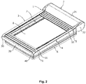
Fig. 2 is an isometric view of a window comprising a screening arrangement with the window in a closed position and the screening body in a screening position (part of the screening body has been removed for clarity); -
Figs. 3a - c is a cross sectional view of a screening body of the present invention; -
Fig. 4 is a schematic representation of a manufacturing process according to the present invention; and -
Fig. 5 is a schematic representation of an alternative manufacturing process according to the present invention; -
Fig. 6 is a schematic representation of another alternative manufacturing process according to the present invention; -
Fig. 7 is a graph showing results of a peel adhesion test comparing various embodiments of the invention with a conventional system. - In the embodiment shown in
Fig. 1 , the screening arrangement in the form of aroller shutter 1 has atop element 2 and twoside rails top element 2. Ashutter body 5 includes a plurality ofslats 51, of which some have been omitted for clarity reasons only. - As shown in
Fig. 2 , theroller shutter 1 can be mounted on a window, for instance a roof window adapted for installation in an inclined roof. The window comprises in a manner known per se awindow frame 6 and a window sash 7 encasing apane 8. The window sash 7 will most often be openable relative to thewindow frame 6, viz. hinge connected to thewindow frame 6, for instance by means of a set of pivot hinges positioned close to a central axis of the window to allow the window sash 7 to pivot relative to thewindow frame 6, or by a more traditional hinge positioned at the top of the window. The aperture to be screened is defined by the area limited by thetop element 2, the side rails 3, 4, and the bottom of the window. This aperture thus corresponds in substance to thepane 8. - In order to attain the desired screening, the
shutter body 5 is adapted to be moved from a non-screening position to a screening position. In the screening position theshutter body 5 covers thepane 8 and other parts of the window to a larger or lesser degree. In the screening position shown inFig. 2 , theshutter body 5 has been rolled out to cover the entire aperture and defines a general screening plane. - The
top element 2 is positioned at the top of the window and comprises in the embodiment shown atop cover 21 and two outer end covers, of which the right-hand end cover 22 is visible inFig. 2 . As will be described in further detail below, thetop cover 21 and outer end 20 covers 22 serve to hide and protect the inner parts of theroller shutter 1, such as for instance the drive mechanisms for the rolling up and unrolling of theshutter body 5. Terms such as "left-hand" and "right-hand" refer to the orientation shown in for instanceFig. 2 and are utilized for reasons of convenience only. - The
side rail 4 has a structure comprising parts that are movable relative to each other. InFig. 2 , only an outerside rail part 41 is visible. Theside rail 4 has abottom cover 40 at the bottom of the window. The side rails 3, 4 are connected to each other at the bottom part of theroller shutter 1, namely by across bar 35 connected to the 30bottom cover 40 ofside rail 4 and its counterpart bottom cover 30 ofside rail 3. Thecross bar 35 may for instance be riveted to eachbottom cover cross bar 35 is not strictly necessary, as sufficient strength may be provided by the side rails 3,4 themselves. - As can be seen from
Fig. 2 , eachslat 51 extends in a longitudinal direction between two end edges and has first and second side edges parallel to the longitudinal direction, i.e. in parallel with thetop element 2. Theshutter body 5 is adapted to be wound up in and rolled out from thetop element 2 by means of a driving device (not shown) in a direction perpendicular to said longitudinal direction to a first screening position. - A cross section of an exemplary embodiment of the screening body of the present invention is shown in
Fig. 3a . Thescreening body 5 has anacrylic fabric layer 301 having atop surface 302 and abottom surface 303. There is a thermoplastic polyurethaneadhesive composition 304 on thebottom surface 303.Aluminium slats epoxy primer coating 307 on the surfaces facing the fabric are positioned adjacent the top andbottom surfaces fabric layer 301. -
Figure 3b shows the adhesive 304 on thetop surface 302 andFigure 3c shows the adhesive 304 on both the top andbottom surfaces - Acrylic fabric is well known to the skilled person. Acrylic fibers are synthetic fibers made from a polymer (polyacrylonitrile) with an average molecular weight of ∼100,000, about 1900 monomer units. For a fiber to be called "acrylic", the polymer generally must contain at least 85% acrylonitrile monomer. Typical comonomers are vinyl acetate or methyl acrylate. Acryl fabrics are generally available for example from Dickson under the tradename sunacryl.
- The acrylic may be solution dyed and coated with an anti-smudge coating which results in very good weather resistance. It will be understood that any suitable fabric may be used in place of the acrylic fabric. For example, a polyester fabric may be used in place of the acrylic in the embodiment described above. Fabrics usable according the invention are obtainable from JM textiles under the name RO Allegro transparent or from Hunter Douglas under the name Baseline Dust Blocks and Green Screen Balance. Alternatively, a polyamide such as Kevlar ® of DuPont may be used. The fabric layer may also be glass fiber or a glass fiber reinforced fabric. The fabric layer may be woven. In further embodiments where the fabric layer comprises glass fiber it may be non-coated or coated. In embodiments where the glass fiber is coated, the coating may be selected from but not limited to PVC or PU. Coated glas fiber reinforced fabric layers suitable according to the invention are available from i.a. Copaco or Phifer.
- The fabric layer is preferably a square construction with the same mechanical performances in warp and weft directions.
- In another embodiment or additionally the warp and weft densities are in the range of 30 and 6 ends respectively per cm, preferably 16-8 ends per cm.
- The yarn used can have a linear mass density in the range of 76 - 540 dtex (i.e. mass in grams per 10,000 meters), preferable 167-420 dtex.
- Such preferred yarns provide a more uniform surface which contibutes to better fixation and an improved lightproof screen.
- It is preferred that the fabric surface is lean, meaning less hairy or complete free of loose single or bundles of loose filaments. The yarn in the fabric may be made of a staplefiber, preferably a combed version or multifilament or monofilament. In a particular embodiment the fabric weight is in the range of 80-300 g/m2, such as 100 to 200 g/m2.
- The thermoplastic polyurethane is preferably aliphatic, such as Elastol-lan ® of BASF Polyurethanes GmbH.
- Even if the adhesive is applied to only one side of the acrylic (or other) fabric it can percolate through the material and can therefore adhere the metal slat on the top surface. It will be appreciated that any suitable adhesive may be used including the thermoplastic copolyester hotmelt film of Gerlinger Industries.
- The coating may be selected from alkyd melamin, epoxy primer or high molecular PE primers, most preferred is epoxy primer. Coatings may also be selected from polyurethane and acrylic. Any other suitable coating known to the skilled person may be used. Epoxy primers are known to the skilled person, suitable epoxy primers according to the present invention include DPLF Epoxy Primer available from Deltron, or similar and usable primers are available from Beckers. Preferred are aromatically based epoxy primers, such as high molecular weight epoxy resins based on Bisphenol A, more specifically 2,2-bis(p-glycidyloxyphenyl) propane condensation product with 2,2-bis(p-hydroxyphenyl) propane and similar isomers and/or phenol, 4,4'-(1-methylethylidene)bis-, polymer with 2,2'-[(1-methylethylidene)bis(4,1- phenyleneoxymethylene)] bis(oxirane) illustrated below by formula (I)

- In the embodiment shown, the metal slats are made from EN AW-5754, which is an aluminium alloy having an aluminium content of greater than 90 wt%. In particular, it has the following composition: aluminium: 94.2 to 97.4%, chromium: 0.3% max, copper: 0.1% max, iron: 0.4% max, magnesium: 2.6 to 3.6%, manganese: 0.5% max, silicon: 0.4% max, titanium: 0.15% max, zinc: 0.2% max and 0.15% max of residuals. Suitable alternatives include EN AW-5006 and EN AW-3005, although any suitable metal known to the skilled person may be used. Particularly preferred are EN AW-5754 or EN AW-3005 having a good stability towards corrosion. Metal strips usable according to the present invention may be obtained from Elval or Novelis.
- In an exemplary method of manufacturing the
screening body 5 depicted infigure 4 , afabric layer 401 and anadhesive layer 402 are simultaneously fed to aguide roll 403 to produce a combinedfabric adhesive layer 404. Theadhesive layer 402 has aremovable liner 405 which prevents the adhesive becoming stuck to theguide roll 403. Once thefabric layer 401 andadhesive layer 402 have passed through theguide roll 403 theliner 405 can be removed. - The combined
fabric adhesive layer 404 can then be passed to ahot air oven 406. Here the adhesive softens and is thus primed for adhesion with further layers. It will be understood that the temperature to which the hot air oven should be heated will depend on the adhesive. Typically, a temperature in the range of around 120 ° to 180°C, preferably 130°C to 160°C, most preferred 145°C is appropriate.Rollers 407 can be used in thehot air oven 406. Alternatively and preferably, the heat is provided from therollers 407 comprising a heating element. - Next, one or two preheated aluminium strips are brought into contact with the combined fabric adhesive layer. If one aluminium strip is used, it may be provided on the top or bottom surface of the combined fabric adhesive layer. If two aluminium strips are used, one will be provided on the top surface of the combined fabric adhesive layer and the other will be provided on the bottom surface said strips being provided to completely cover each other.
- The aluminium strips are coated before the optional heating, preferably well before the manufacturing method to allow the coating to dry and cure.
- The combined
fabric adhesive layer 404 andaluminium layers further rollers 410 and into a furtherhot air oven 411 where the combination is heated. Again, a temperature of around 145°C is typically suitable.Non-stick rollers 412 in thehot air oven 411 encourage the layers to adhere to one another and allow thescreening body 5 formed to move through thehot air oven 411. Acooling section 414 can then be used to allow the adhesive to set. If necessary, the screening body can then be cut to shape. - In the alternative embodiment shown in
Fig. 5 , afabric layer 501, anadhesive layer 502 andaluminium layers guide roll 510. The aluminium layers 508, 509 are coated before being introduced, preferably well before the manufacturing method to allow the coating to dry and cure. - The combination is then passed to a temperature controlled
section 511 in which there is aheating section 520 and acooling section 522. Whilst any suitable temperatures may be used, a temperature of around 120 ° to 180°C, preferably 130°C to 160°C, most preferred 145°C is typically appropriate for theheating section 520. - Guide rolls 512 allow the screening body formed to move through the temperature controlled
section 511. In addition to guiderolls 512, there may be further rollers in theheating section 520 and/or thecooling section 522.Belts heating section 520 and/or thecooling section 522 to apply a constant pressure to thescreening body 5, the pressure applied is typically around 18 MPa. - In the alternative embodiment shown in
Fig. 6 , afabric layer 601 andadhesive layer 602 are simultaneously fed tofirst rolling section 603a. Thefirst rolling section 603a comprises afirst guide roll 603b and asecond guide roll 603c separated by aheating portion 603d. Thefabric layer 601 andadhesive layer 602 pass through thefirst guide roll 603b and are heated to soften the adhesive inheating portion 603d. One ormore belts 603e may be used in theheating portion 603d to maintain the desired pressure. The fabric and adhesive then pass throughsecond guide roll 603c andremovable liner 605 is removed from the adhesive. - After the liner has been removed, an
intermediate heater 630 is used to keep the adhesive at a temperature at which it is sticky but not molten. It will be understood that the specific temperature required to achieve this will depend on factors such as the type of adhesive used, although typically a temperature of around 70°C to 90°C is appropriate. - Aluminium layers 608 and 609 are fed with the fabric-adhesive combination to further
rollers 610.Preheaters section 611 in which there is aheating section 620 and acooling section 622. Whilst any suitable temperatures may be used, a temperature of around 120 ° to 180°C, preferably 130°C to 160°C, most preferred 145°C is typically appropriate for theheating section 620. - Guide rolls 612 allow the screening body formed to move through the temperature controlled
section 611. In addition to guiderolls 612, there may be further rollers in theheating section 620 and/or thecooling section 622. Belts may be used in theheating section 620 and/or thecooling section 622 to apply a constant pressure and/or heat to thescreening body 5. - It will be understood that the aluminium strips are coated before heating, preferably well before the manufacturing method to allow the coating to dry and cure.
- Different stages of the process may require different pressures. For example, the pressure applied by guide rolls 603b, 603c, 610 and 612 and any corresponding belts can be tailored according to the requirements of the process. In some embodiments, the pressure applied to the sample in the
first rolling section 603a will be different from the pressure applied by therollers 610 and/or therollers 612. - The heat applied in
heating portion 603d may be different from the heat applied byheating section 620. The temperature in these sections may be independently adjustable. - In order to test various embodiments of the screening body of the present invention and compare their characteristics with a conventional screening body, a peel test was conducted.
- The peel test was carried out in accordance with the following industry standards: BS 5350-C12, ASTM D5170, ASTM F88 and ISO 11339.
- Four embodiments of the present invention were tested. Each had the structure outlined in
Fig. 3 , but with the materials selected as follows:Embodiment 1Embodiment 2Embodiment 3Embodiment 4Coating Epoxy Polyethylene Terephthalate Epoxy Polyethylene Tere phthalate Fabric Acrylic Acrylic Acrylic Acrylic Adhesive Thermoplastic Polyurethane Thermoplastic Polyurethane Polyethylene Terephthalate Polyethylene Terephthalate Metal Aluminium Aluminium Aluminium Aluminium - The performance of the embodiments of the invention were compared with that of a commercially available product in which the fabric was poly ethylenetere phthalate (PET), the fabric layer polyethylene and an adhesive (not known).
- A number of tests were conducted under a variety of conditions intended to replicate the conditions that a screening body may encounter during use
Stress factors Degradation mechanisms Accelerated tests Elevated temperature. Screening body can reach 80-85°C Speed up degradation process of hydrolysis, oxidation etc. Climate test @ 85°C, 80% RH Florida test* (peel test) Moisture/water The fabric and adhesive absorb water Hydrolysis of adhesive, fabric and primer. Water react with polymer and break down the polymer chain Climate test @85°C, 80 % RH Xenon test Florida test Water emission test Low temperature. Water freezes to ice Water expansion. Stress the construction and the adhesive interface Cataplasmatest 70°C, 100 %RH to -20°C UV radiation Polymer degradation. Stimulate the oxidation process, creates free radicals and can lead to polymer chain breaks Xenon test QUV B Florida test - Tests indicated with "*" are future suitable tests to be performed
- To provide a comparison, the peel test was also conducted when no ageing process was applied to the samples.
- The results of the peel test can be found in
Fig. 7 . - As can be seen, the samples in accordance with the present invention were able to withstand a greater load under at least some of the test conditions compared with the commercially available sample. Some of the samples, namely those of
embodiments - Following the initial peel test, further tests were conducted. Additional embodiments were tested which were analogous to those of
embodiments Embodiment 1Embodiment 3Embodiment 5Embodiment 6Coating Epoxy Epoxy Epoxy Epoxy Fabric Acrylic Acrylic Polyester Polyester Adhesive Thermoplastic Polyurethane Polyethylene Terephthalate Thermoplastic Polyurethane Polyethylene Terephthalate Metal Aluminium Aluminium Aluminium Aluminium - A general summary of the results can be found in the table below. The
number 1 represents a positive result, 2 represents a need for further investigation and 3 represents a result under average. The score was based on an overall evaluation of the sum of parameters and properties tested.Embodiment 1Embodiment 3Embodiment 5Embodiment 6Commerically available product Adhesion and Delamination 1 2 2 3 3 UV Stability 1 2 2 2 2 Black-out 1 1 1 1 1 Resist surface temperatures of -25°C to 80° C 1 1 1 1 1 Resist humidity 1 3 3 3 3 Process (producible) 1 1 1 1 - - Particularly favorable characteristics were observed for
embodiment 1. This embodiment has the structure shown inFig. 3 with aluminium metal layers, an epoxy coating on the aluminium, acrylic fabric and an aliphatic thermoplastic polyurethane adhesive.Embodiment 5, in which the structure is identical toembodiment 3 except that the fabric is polyester rather than acrylic, also showed surprisingly positive results.
Claims (20)
- A screening body for a screening arrangement including a top element defining a longitudinal direction, said screening body comprising a plurality of slats and a fabric layer having a top surface and a bottom surface, each slat extending in a longitudinal direction between two end edges and having first and second side edges parallel to the longitudinal direction, the screening body being adapted to be wound up in and rolled out from said top element in a direction perpendicular to said longitudinal direction to a screening position in which the screening body defines a general screening plane; in which each of the slats is composed of at least one metal strip connected to the fabric layer,
the screening body being characterised in that the at least one metal strip is coated on at least the side facing the fabric layer and that an adhesive layer binds the metal strip to the fabric layer. - A screening body according to claim 1, wherein the at least first metal strip is arranged to contact the top surface of the fabric layer and a second metal strip is arranged to contact the bottom surface of the fabric layer.
- A screening body according to Claim 1 or 2, wherein the at least one first metal strip comprises aluminium.
- A screening body according to claim 3, wherein the at least one metal strip comprises an alloy having an Al content in an amount of at least 90 wt% or more preferably at least 93 wt%, most preferred at least 95%.
- A screening body according to any one of the preceding claims, wherein the coating comprises epoxy, polyethylene, such as polyethylene terephtalate (PET), polyurethane, acrylic or melamine, preferably the coating is an aromatically based epoxy.
- A screening body according to any one of the preceding claim, wherein the adhesive composition comprises thermoplastic polyurethane or polyethylene terephthalate, more preferred an aliphatic thermoplastic polyurethane, even more preferred an aliphatic polyether polyurethane.
- A screening body according to anyone of the preceding claims, wherein the adhesive layer has been applied to the bottom surface of the fabric layer.
- A screening body according to any one of the preceding claims, wherein the adhesive composition additionally comprises and/or is a UV stabiliser.
- A screening body according to any one of the preceding claims, wherein the fabric layer comprises acrylic, polyester, glass fiber, a glass fiber reinforced layer or a polyamide.
- A screening body according to any of the preceding claims, wherein the fabric layer comprises acrylic or polyester, the at least one first metal strips comprises an alloy having an aluminium content in an amount of at least 90 wt%, the adhesive composition comprises a thermoplastic polyurethane and the coating comprises epoxy.
- A screening arrangement for an aperture of a building structure, the screening arrangement comprising:a top element arranged to be mountable to a top member of a window frame,two side rails, anda screening body according to any one of the preceding claims.
- A method of manufacturing a screening body according to any of the claims 1 to 10, the method comprising the steps of:i. feeding a fabric layer to a guiding roll said fabric comprising a top surface and a bottom surface;ii. contacting the fabric layer with an adhesive composition layer to provide a combined fabric adhesive layer,iii. heating the fabric adhesive layer to a temperature at which the adhesive softens, such as a temperature in the range of 120 ° to 180°C, preferably 130°C to 160°C, most preferred 145°C;v. in successive steps optionally pre-heating an at least first coated metal strip;vi. providing the, optionally heated, at least first metal strip to the upper surface of the fabric adhesive layer in in successive steps extending in a longitudinal direction of the fabric adhesive layer;vii. heating the fabric adhesive layer and the metal strip(s) to obtain the screening body.
- Method according to claim 12, wherein step vi. comprises providing heated metal strips to each sides of the fabric adhesive layer.
- Method according to claim 12 or 13, wherein the adhesive layer is applied to the bottom surface of the fabric layer.
- Method according to any one of claims 12 to 14, wherein the adhesive layer is provided as a lined adhesive layer or wherein the adhesive layer is provided by extrusion immediately prior to being contacted with the fabric layer in step ii.
- Method according to any one of claims 12 to 15, wherein the heating of step iii. and vii. takes place at the same temperature, preferably in the same heating unit.
- Method according to any one of claims 12 to 16, wherein the method further comprises the step of cooling the fabric adhesive layer and the metal strip(s) after they have been heated in step vii.
- Method according to any one of claims 12 to 17, wherein the method is flatbed lamination.
- Method according to any one of claims 12 to 18, wherein the fabric layer is heated prior to being provided in step i. or wherein an adhesive is applied to the fabric under heating prior to being provided in step i.
- Method according to any one of claims 12 to 19, wherein the adhesion layer is applied to both the bottom and top surfaces of the fabric layer and wherein the pressure applied in the lamination process is below 100 bar, such as below 50 bar.
Applications Claiming Priority (1)
| Application Number | Priority Date | Filing Date | Title |
|---|---|---|---|
| DKPA201770241 | 2017-04-03 |
Publications (2)
| Publication Number | Publication Date |
|---|---|
| EP3385490A1 true EP3385490A1 (en) | 2018-10-10 |
| EP3385490B1 EP3385490B1 (en) | 2024-01-17 |
Family
ID=61750024
Family Applications (1)
| Application Number | Title | Priority Date | Filing Date |
|---|---|---|---|
| EP18163303.3A Active EP3385490B1 (en) | 2017-04-03 | 2018-03-22 | Screening body with improved weather resistance, uv resistance and lamination properties |
Country Status (1)
| Country | Link |
|---|---|
| EP (1) | EP3385490B1 (en) |
Cited By (1)
| Publication number | Priority date | Publication date | Assignee | Title |
|---|---|---|---|---|
| WO2021104592A1 (en) * | 2019-11-25 | 2021-06-03 | Vkr Holding A/S | External screening arrangement with a set of lamellas |
Citations (3)
| Publication number | Priority date | Publication date | Assignee | Title |
|---|---|---|---|---|
| EP0806541A2 (en) * | 1996-05-08 | 1997-11-12 | Paul Baier | Lamella for a roller shutter, method for producing a lamella and device forcoating a shutter |
| WO1998020225A1 (en) * | 1996-11-01 | 1998-05-14 | Velux Industri A/S | A roller shutter for windows, doors and the like and a method of manufacturing |
| EP1048817A1 (en) * | 1999-04-26 | 2000-11-02 | Johann Henkenjohann | Method of producing a metal foil - textile combination, in particular for roller shutters |
-
2018
- 2018-03-22 EP EP18163303.3A patent/EP3385490B1/en active Active
Patent Citations (3)
| Publication number | Priority date | Publication date | Assignee | Title |
|---|---|---|---|---|
| EP0806541A2 (en) * | 1996-05-08 | 1997-11-12 | Paul Baier | Lamella for a roller shutter, method for producing a lamella and device forcoating a shutter |
| WO1998020225A1 (en) * | 1996-11-01 | 1998-05-14 | Velux Industri A/S | A roller shutter for windows, doors and the like and a method of manufacturing |
| EP1048817A1 (en) * | 1999-04-26 | 2000-11-02 | Johann Henkenjohann | Method of producing a metal foil - textile combination, in particular for roller shutters |
Cited By (1)
| Publication number | Priority date | Publication date | Assignee | Title |
|---|---|---|---|---|
| WO2021104592A1 (en) * | 2019-11-25 | 2021-06-03 | Vkr Holding A/S | External screening arrangement with a set of lamellas |
Also Published As
| Publication number | Publication date |
|---|---|
| EP3385490B1 (en) | 2024-01-17 |
Similar Documents
| Publication | Publication Date | Title |
|---|---|---|
| RU2465536C2 (en) | Armoured glass | |
| EP3198101A1 (en) | Spacer for insulating glazing units | |
| EP3357683B1 (en) | Room darkening material and architectural covering made from same | |
| US20020038684A1 (en) | Hinged thermoplastic-fabric reinforced structural member, profile and methods therefore | |
| WO2013104507A1 (en) | Spacer for insulating glazing units | |
| EP3385490B1 (en) | Screening body with improved weather resistance, uv resistance and lamination properties | |
| US20200061959A1 (en) | Multilayer composite material having light-transmission and tensile properties | |
| DE202016008432U1 (en) | Door for refrigerated container furniture | |
| US9140062B2 (en) | Easy roll stiff screen | |
| DE202020106850U1 (en) | Asymmetrical hybrid automotive laminate | |
| US20180016736A1 (en) | Composition for fiber adhesion and fabrics using the same | |
| DE102020108568A1 (en) | Profile for a window and / or door part with a metal layer with a fiber layer | |
| WO2007137743A2 (en) | Carrier unit for a solar cell unit | |
| EP3433100B1 (en) | Architectural membrane | |
| KR102493501B1 (en) | Building Membrane Structures with improved fire resistance, contamination, durability, and weather resistance | |
| EP0403969B1 (en) | Textile fabric with flame resistant polyestermonofilaments | |
| AT517402B1 (en) | Photovoltaic element | |
| EP3309501A1 (en) | Framed, transparent and bullet resistant glasing with enforced boundary | |
| JP2022542824A (en) | Resin composition for optical film | |
| KR102493502B1 (en) | Manufacturing Method of Building Membrane Structures with improved fire resistance, contamination, durability, and weather resistance | |
| US20230166489A1 (en) | Transparent fire-retardant composite material | |
| WO2023198709A1 (en) | Spacer having improved mechanical stiffness | |
| JP6107233B2 (en) | Polycarbonate resin laminate, folded plate, and corrugated plate | |
| DE102012020270A1 (en) | Composite plate for e.g. rear window in motor vehicle e.g. passenger car, has fabric element with coating for reflecting on composite plate incident light is provided in regions between inner pane and outer pane |
Legal Events
| Date | Code | Title | Description |
|---|---|---|---|
| PUAI | Public reference made under article 153(3) epc to a published international application that has entered the european phase |
Free format text: ORIGINAL CODE: 0009012 |
|
| STAA | Information on the status of an ep patent application or granted ep patent |
Free format text: STATUS: THE APPLICATION HAS BEEN PUBLISHED |
|
| AK | Designated contracting states |
Kind code of ref document: A1 Designated state(s): AL AT BE BG CH CY CZ DE DK EE ES FI FR GB GR HR HU IE IS IT LI LT LU LV MC MK MT NL NO PL PT RO RS SE SI SK SM TR |
|
| AX | Request for extension of the european patent |
Extension state: BA ME |
|
| STAA | Information on the status of an ep patent application or granted ep patent |
Free format text: STATUS: REQUEST FOR EXAMINATION WAS MADE |
|
| 17P | Request for examination filed |
Effective date: 20190402 |
|
| RBV | Designated contracting states (corrected) |
Designated state(s): AL AT BE BG CH CY CZ DE DK EE ES FI FR GB GR HR HU IE IS IT LI LT LU LV MC MK MT NL NO PL PT RO RS SE SI SK SM TR |
|
| STAA | Information on the status of an ep patent application or granted ep patent |
Free format text: STATUS: EXAMINATION IS IN PROGRESS |
|
| 17Q | First examination report despatched |
Effective date: 20191122 |
|
| STAA | Information on the status of an ep patent application or granted ep patent |
Free format text: STATUS: EXAMINATION IS IN PROGRESS |
|
| STAA | Information on the status of an ep patent application or granted ep patent |
Free format text: STATUS: EXAMINATION IS IN PROGRESS |
|
| GRAP | Despatch of communication of intention to grant a patent |
Free format text: ORIGINAL CODE: EPIDOSNIGR1 |
|
| STAA | Information on the status of an ep patent application or granted ep patent |
Free format text: STATUS: GRANT OF PATENT IS INTENDED |
|
| INTG | Intention to grant announced |
Effective date: 20230929 |
|
| GRAS | Grant fee paid |
Free format text: ORIGINAL CODE: EPIDOSNIGR3 |
|
| GRAA | (expected) grant |
Free format text: ORIGINAL CODE: 0009210 |
|
| STAA | Information on the status of an ep patent application or granted ep patent |
Free format text: STATUS: THE PATENT HAS BEEN GRANTED |
|
| AK | Designated contracting states |
Kind code of ref document: B1 Designated state(s): AL AT BE BG CH CY CZ DE DK EE ES FI FR GB GR HR HU IE IS IT LI LT LU LV MC MK MT NL NO PL PT RO RS SE SI SK SM TR |
|
| REG | Reference to a national code |
Ref country code: GB Ref legal event code: FG4D |
|
| REG | Reference to a national code |
Ref country code: CH Ref legal event code: EP |
|
| REG | Reference to a national code |
Ref country code: DE Ref legal event code: R096 Ref document number: 602018064174 Country of ref document: DE |
|
| REG | Reference to a national code |
Ref country code: IE Ref legal event code: FG4D |
|
| REG | Reference to a national code |
Ref country code: NL Ref legal event code: FP |
|
| PGFP | Annual fee paid to national office [announced via postgrant information from national office to epo] |
Ref country code: NL Payment date: 20240214 Year of fee payment: 7 |
|
| PGFP | Annual fee paid to national office [announced via postgrant information from national office to epo] |
Ref country code: DE Payment date: 20240206 Year of fee payment: 7 |