EP3385104A1 - Montagebaugruppe - Google Patents
Montagebaugruppe Download PDFInfo
- Publication number
- EP3385104A1 EP3385104A1 EP18163544.2A EP18163544A EP3385104A1 EP 3385104 A1 EP3385104 A1 EP 3385104A1 EP 18163544 A EP18163544 A EP 18163544A EP 3385104 A1 EP3385104 A1 EP 3385104A1
- Authority
- EP
- European Patent Office
- Prior art keywords
- mounting
- opening
- auxiliary
- auxiliary unit
- assembly according
- Prior art date
- Legal status (The legal status is an assumption and is not a legal conclusion. Google has not performed a legal analysis and makes no representation as to the accuracy of the status listed.)
- Granted
Links
Images
Classifications
-
- B—PERFORMING OPERATIONS; TRANSPORTING
- B60—VEHICLES IN GENERAL
- B60K—ARRANGEMENT OR MOUNTING OF PROPULSION UNITS OR OF TRANSMISSIONS IN VEHICLES; ARRANGEMENT OR MOUNTING OF PLURAL DIVERSE PRIME-MOVERS IN VEHICLES; AUXILIARY DRIVES FOR VEHICLES; INSTRUMENTATION OR DASHBOARDS FOR VEHICLES; ARRANGEMENTS IN CONNECTION WITH COOLING, AIR INTAKE, GAS EXHAUST OR FUEL SUPPLY OF PROPULSION UNITS IN VEHICLES
- B60K13/00—Arrangement in connection with combustion air intake or gas exhaust of propulsion units
- B60K13/04—Arrangement in connection with combustion air intake or gas exhaust of propulsion units concerning exhaust
-
- F—MECHANICAL ENGINEERING; LIGHTING; HEATING; WEAPONS; BLASTING
- F01—MACHINES OR ENGINES IN GENERAL; ENGINE PLANTS IN GENERAL; STEAM ENGINES
- F01N—GAS-FLOW SILENCERS OR EXHAUST APPARATUS FOR MACHINES OR ENGINES IN GENERAL; GAS-FLOW SILENCERS OR EXHAUST APPARATUS FOR INTERNAL-COMBUSTION ENGINES
- F01N13/00—Exhaust or silencing apparatus characterised by constructional features
- F01N13/18—Construction facilitating manufacture, assembly, or disassembly
- F01N13/1805—Fixing exhaust manifolds, exhaust pipes or pipe sections to each other, to engine or to vehicle body
-
- F—MECHANICAL ENGINEERING; LIGHTING; HEATING; WEAPONS; BLASTING
- F16—ENGINEERING ELEMENTS AND UNITS; GENERAL MEASURES FOR PRODUCING AND MAINTAINING EFFECTIVE FUNCTIONING OF MACHINES OR INSTALLATIONS; THERMAL INSULATION IN GENERAL
- F16B—DEVICES FOR FASTENING OR SECURING CONSTRUCTIONAL ELEMENTS OR MACHINE PARTS TOGETHER, e.g. NAILS, BOLTS, CIRCLIPS, CLAMPS, CLIPS OR WEDGES; JOINTS OR JOINTING
- F16B37/00—Nuts or like thread-engaging members
- F16B37/04—Devices for fastening nuts to surfaces, e.g. sheets, plates
-
- F—MECHANICAL ENGINEERING; LIGHTING; HEATING; WEAPONS; BLASTING
- F16—ENGINEERING ELEMENTS AND UNITS; GENERAL MEASURES FOR PRODUCING AND MAINTAINING EFFECTIVE FUNCTIONING OF MACHINES OR INSTALLATIONS; THERMAL INSULATION IN GENERAL
- F16B—DEVICES FOR FASTENING OR SECURING CONSTRUCTIONAL ELEMENTS OR MACHINE PARTS TOGETHER, e.g. NAILS, BOLTS, CIRCLIPS, CLAMPS, CLIPS OR WEDGES; JOINTS OR JOINTING
- F16B37/00—Nuts or like thread-engaging members
- F16B37/02—Nuts or like thread-engaging members made of thin sheet material
-
- F—MECHANICAL ENGINEERING; LIGHTING; HEATING; WEAPONS; BLASTING
- F16—ENGINEERING ELEMENTS AND UNITS; GENERAL MEASURES FOR PRODUCING AND MAINTAINING EFFECTIVE FUNCTIONING OF MACHINES OR INSTALLATIONS; THERMAL INSULATION IN GENERAL
- F16B—DEVICES FOR FASTENING OR SECURING CONSTRUCTIONAL ELEMENTS OR MACHINE PARTS TOGETHER, e.g. NAILS, BOLTS, CIRCLIPS, CLAMPS, CLIPS OR WEDGES; JOINTS OR JOINTING
- F16B37/00—Nuts or like thread-engaging members
- F16B37/04—Devices for fastening nuts to surfaces, e.g. sheets, plates
- F16B37/06—Devices for fastening nuts to surfaces, e.g. sheets, plates by means of welding or riveting
- F16B37/061—Devices for fastening nuts to surfaces, e.g. sheets, plates by means of welding or riveting by means of welding
-
- F—MECHANICAL ENGINEERING; LIGHTING; HEATING; WEAPONS; BLASTING
- F16—ENGINEERING ELEMENTS AND UNITS; GENERAL MEASURES FOR PRODUCING AND MAINTAINING EFFECTIVE FUNCTIONING OF MACHINES OR INSTALLATIONS; THERMAL INSULATION IN GENERAL
- F16B—DEVICES FOR FASTENING OR SECURING CONSTRUCTIONAL ELEMENTS OR MACHINE PARTS TOGETHER, e.g. NAILS, BOLTS, CIRCLIPS, CLAMPS, CLIPS OR WEDGES; JOINTS OR JOINTING
- F16B39/00—Locking of screws, bolts or nuts
- F16B39/02—Locking of screws, bolts or nuts in which the locking takes place after screwing down
-
- F—MECHANICAL ENGINEERING; LIGHTING; HEATING; WEAPONS; BLASTING
- F16—ENGINEERING ELEMENTS AND UNITS; GENERAL MEASURES FOR PRODUCING AND MAINTAINING EFFECTIVE FUNCTIONING OF MACHINES OR INSTALLATIONS; THERMAL INSULATION IN GENERAL
- F16B—DEVICES FOR FASTENING OR SECURING CONSTRUCTIONAL ELEMENTS OR MACHINE PARTS TOGETHER, e.g. NAILS, BOLTS, CIRCLIPS, CLAMPS, CLIPS OR WEDGES; JOINTS OR JOINTING
- F16B41/00—Measures against loss of bolts, nuts, or pins; Measures against unauthorised operation of bolts, nuts or pins
- F16B41/002—Measures against loss of bolts, nuts or pins
-
- F—MECHANICAL ENGINEERING; LIGHTING; HEATING; WEAPONS; BLASTING
- F16—ENGINEERING ELEMENTS AND UNITS; GENERAL MEASURES FOR PRODUCING AND MAINTAINING EFFECTIVE FUNCTIONING OF MACHINES OR INSTALLATIONS; THERMAL INSULATION IN GENERAL
- F16B—DEVICES FOR FASTENING OR SECURING CONSTRUCTIONAL ELEMENTS OR MACHINE PARTS TOGETHER, e.g. NAILS, BOLTS, CIRCLIPS, CLAMPS, CLIPS OR WEDGES; JOINTS OR JOINTING
- F16B5/00—Joining sheets or plates, e.g. panels, to one another or to strips or bars parallel to them
- F16B5/02—Joining sheets or plates, e.g. panels, to one another or to strips or bars parallel to them by means of fastening members using screw-thread
-
- B—PERFORMING OPERATIONS; TRANSPORTING
- B62—LAND VEHICLES FOR TRAVELLING OTHERWISE THAN ON RAILS
- B62D—MOTOR VEHICLES; TRAILERS
- B62D27/00—Connections between superstructure or understructure sub-units
- B62D27/06—Connections between superstructure or understructure sub-units readily releasable
- B62D27/065—Connections between superstructure or understructure sub-units readily releasable using screwthread
Definitions
- the present invention relates to a mounting assembly, which can be used, for example, to set in a motor vehicle, a component, such as an exhaust system to the motor vehicle.
- Such a mounting assembly may comprise a bow-like trained and constructed of metal material mounting member, on the one hand for attachment to a component to be determined by this component, for example, an exhaust system, and on the other hand has at least one Montageelement tillgriffsö réelle through which a fastening bolt, such as a bolt passed can be so that after application of a nut on the bolt a firm connection is realized.
- a fastening bolt such as a bolt passed can be so that after application of a nut on the bolt a firm connection is realized.
- the connection to be determined by means of the mounting element component can be done in this way.
- a mounting assembly comprising a mounting element to be fixed by means of at least one fastening bolt, wherein at least one mounting element through opening is provided for the passage of at least one fastening bolt, wherein an assembly auxiliary unit is provided on the mounting element in association with at least one mounting element through opening the mounting auxiliary unit in association with the mounting element through-opening has a mounting auxiliary passage opening arranged in such a way aligned with the mounting element through-opening that an edge region of the mounting auxiliary unit surrounding the mounting auxiliary passage opening is arranged partially overlapping the mounting element through opening.
- a mounting aid unit providing a cohesion with one or more fastening bolts is provided on the mounting element itself in the case of the assembly assembly according to the invention, the functionality of a securing bolt secured in this way in the further assembly, in particular the interaction with a locking element, such as a nut or the like, through the Assembly aid unit not affected.
- the mounting auxiliary unit with two mutually opposite sections of the edge region, the mounting element through opening is arranged partially overlapping.
- a reliable holding effect can be ensured that a distance between the two portions of the edge region is smaller than a Outer diameter of a mounting bolt through which the mounting element through opening to be positioned or positioned.
- the mounting element through opening is elongate and has an opening width transverse to its longitudinal direction, wherein the opening width is greater than an outer diameter of the mounting element through-opening to be positioned or positioned fastening bolt.
- the mounting element through opening is thus designed in the manner of a slot and allows the movement of a fastening bolt passing through this, in particular in the direction of the longitudinal extension of the mounting element through opening.
- the mounting auxiliary unit through opening is elongated and has an opening width, wherein an opening width of the mounting auxiliary unit passage opening is smaller than the opening width of the mounting member through-opening.
- an opening width of the mounting auxiliary unit passage opening is smaller than the opening width of the mounting member through-opening.
- the assembly aid unit comprises a mounting auxiliary element, and that the mounting auxiliary unit through-opening is an opening formed in the mounting auxiliary element.
- the mounting aid is particularly easy to handle and to position relative to the mounting member when the opening formed in the mounting auxiliary member is closed.
- the mounting assist unit may comprise two mounting assist members arranged to provide a space forming the mounting assist passage opening.
- each of the two auxiliary mounting elements can provide one of the sections of the edge region.
- the mounting auxiliary unit have a thickness of less than 0.1 mm, preferably less than 0.08 mm, most preferably about zero , 05 mm.
- Such a thin mounting auxiliary element can remain as a lost component between the mounting element and the assembly to be assembled with this, without causing any impairment of the system thus constructed.
- the mounting aid unit may be constructed of metal material.
- the mounting auxiliary unit may be fixed to the mounting member by welding, preferably spot welding.
- the mounting assembly constructed in accordance with the invention can be provided such that at least one fastening bolt is held in at least one mounting element through opening by an assembly aid unit associated with the mounting member through opening.
- At least one fastening bolt can be, for example, a screw bolt.
- mounting member through-holes may be provided in a mounting member, advantageously but not necessarily Each mounting element through opening may be associated with a mounting auxiliary unit. If several mounting auxiliary units are provided on a mounting element, they can be designed to be the same or different from one another.
- the Fig. 1 shows a plan view of a mounting assembly 10, which can be used, for example, to set an exhaust system on the motor vehicle in a motor vehicle.
- the mounting assembly 10 includes a bow-shaped mounting member 12 formed, for example, of sheet metal material, in which two mounting member through holes 14, 16 are formed.
- the two Montageelement sacrifice Schlö Anlagenen are elongated and thus formed on the type of respective slots. They have transversely to their longitudinal extent an opening width B which is greater than the diameter of a fastening bolt to be positioned therethrough.
- Such a fastening bolt is preferably designed as a screw bolt and can be used by cooperation with a designed as a nut or the like locking member for fixing the mounting assembly 10.
- an assembly auxiliary unit 18a or 18b is provided in each case.
- These mounting auxiliary units 18a, 18b ensure that before the attachment of a locking element, so for example a nut, at a respectively assigned Montageelement tillgriffsö réelle 14 and 16 passing through fastening bolts unintentional release of such mounting bolts is prevented by the mounting member 12 and a detachment of the mounting member 12 is prevented by a respective mounting member through-opening 14 and 16 passing through fastening bolts.
- the mounting auxiliary unit 18a provided in association with the mounting element through opening 14 comprises a mounting auxiliary element 20 constructed of very thin metal material, preferably sheet metal material.
- the auxiliary mounting element 20 preferably has a thickness in the range of 0.05 mm and is fixedly connected to the mounting element 12, for example by spot welding ,
- the auxiliary mounting member 20 has a mounting auxiliary passage opening 22a in association with the mounting member through-hole 14. Also, in association with the elongated configuration of the mounting member through-hole 14, the mounting-auxiliary-unit through-hole 22a is elongated and has an opening width b smaller than the opening width B of the mounting member through-hole 12.
- the extension length of the mounting-auxiliary-unit through-hole 22a is substantially equal to the extension length of the mounting-member through-hole 14, but may also be be slightly larger or smaller than this.
- the auxiliary assembly element 20 is positioned with its mounting aid unit through opening 22a with respect to the mounting element through-opening 14 such that, for example, longitudinal center axes of these two openings are aligned with each other.
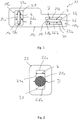
- the Fig. 2 shows the auxiliary mounting member 20 in cooperation with the mounting element through-opening 14 and also the mounting aid through-opening 22a passing through fastening bolts 30 which is formed for example as a screw bolt.
- the opening width b is matched to the diameter D of the fastening element 30 generally provided with a substantially circular cross-sectional geometry such that the opening width b is smaller than the diameter D.
- the mounting element through-opening 14 is dimensioned such that its opening width B is at least slightly larger is as the diameter D, so that the mounting bolt 30, the mounting element through-opening 14 can be positioned across and at the mounting element through-opening 14 by cross-fastening bolt 30, the mounting member 12 can be brought into its intended for installation location.
- the fastening bolt 30 is also moved through the mounting aid unit through opening 22a and thus locally the auxiliary assembly member 20 in the region of the sections 24a, 26a of the edge region 28a deformed or possibly even destroyed.
- the auxiliary mounting member 20 engages around the mounting auxiliary unit through opening 22 a passing through fastening bolts 30 and can engage in the design of the mounting bolt 30 as a bolt in the external thread thereof.
- the mounting auxiliary unit 18a of the fastening bolts 30 is held in its mounting element through-opening 14 by cross-positioning by the relatively thin auxiliary assembly element 20, but can be moved in the direction of the longitudinal extension of the mounting element through-opening 14 and also the mounting auxiliary unit through opening 22a. Due to the comparatively small thickness of the auxiliary mounting element 20, a damage of the fastening bolt 30 at its outer peripheral area, in particular a thread possibly provided there, excluded.
- the auxiliary assembly member 20 when advantageously in the direction of the opening width, the auxiliary assembly member 20 is centered with respect to the Montageelement begriffsö réelle 14 and thus the two portions 24a, 26a of the edge portion 28a, viewed in the direction of the opening width, substantially the same extent overlap the Montageelement begriffsö réelle 14, is overlapped by the mounting aid 20 additionally achieved a centering effect for the fastening member 30 with respect to the mounting element through opening 14 in the direction of the opening width B.
- auxiliary assembly member 20 is particularly preferred with a closed therein formed auxiliary assembly through opening 22a, especially when using very thin construction material for the auxiliary assembly member 20 due to the easier handling.
- the mounting auxiliary unit through-opening 22a could also be designed to be open on at least one peripheral area, so that, for example, the auxiliary mounting element 20, unlike the illustrated O-shaped configuration, could have a substantially C-shaped configuration.
- the mounting auxiliary unit 18b provided in association with the mounting element through opening 16 comprises two strip-like or auxiliary mounting elements 32, 34.
- Each of these two auxiliary mounting elements 32, 34 is preferably made of very thin metal or sheet material, for example having a thickness in the range of about 0 , 05 mm, provided and fixed by welding, preferably spot welding, on the mounting member 12.
- the two mounting auxiliary elements 32, 34 are positioned with respect to the elongated mounting element through opening 16 so that they extend in the direction of the longitudinal extent of the mounting element through-opening 16 and leave between them a distance 36 providing the mounting auxiliary unit through opening 22b.
- This distance 36 defining the opening width b of the mounting assist passage opening 22b is so dimensioned to be slightly smaller than the opening width B of the mounting member through-hole 16.
- Fig. 1 shown in association with one and the same mounting element assembly units of different types can be used, but in principle also identical mounting auxiliary units can be provided. Furthermore, it is of course possible that if a plurality of mounting element through openings are provided on a mounting element, only in association with such a mounting element through opening a mounting auxiliary unit can be provided or should, in which a backup function is to be realized.
- Such a mounting assembly constructed in accordance with the invention may, in association with one or more mounting element through-openings, comprise a fastening bolt positioned therethrough and secured by an associated mounting aid unit and then arranged and secured as a preassembly assembly at the appropriate position.
- each of a mounting element through-opening to be positioned by means of fastening bolts could also be pre-assembled in each case to that module on which the mounting assembly is to be defined. This may then be positioned upon attachment so that the mounting bolts already provided on the other assembly pass through the mounting aid unit passages in the mounting assembly.
- the structure of the mounting auxiliary units of comparatively thin sheet metal material is particularly advantageous, it is understood that other materials such. As film-like plastic material, can be used, such materials can then be determined for example by gluing on a mounting element.
Landscapes
- Engineering & Computer Science (AREA)
- General Engineering & Computer Science (AREA)
- Mechanical Engineering (AREA)
- Chemical & Material Sciences (AREA)
- Combustion & Propulsion (AREA)
- Transportation (AREA)
- Connection Of Plates (AREA)
Abstract
Description
- Die vorliegende Erfindung betrifft eine Montagebaugruppe, welche beispielsweise genutzt werden kann, um in einem Kraftfahrzeug eine Komponente, beispielsweise einer Abgasanlage, an dem Kraftfahrzeug festzulegen.
- Eine derartige Montagebaugruppe kann ein bügelartig ausgebildetes und aus Metallmaterial aufgebautes Montageelement umfassen, das einerseits zur Befestigung an einer durch dieses festzulegenden Komponente, beispielsweise einer Abgasanlage, ausgebildet ist, und das andererseits zumindest eine Montageelementdurchgriffsöffnung aufweist, durch welche ein Befestigungsbolzen, beispielsweise ein Schraubbolzen, hindurchgeführt werden kann, so dass nach Aufbringen einer Mutter auf den Schraubbolzen eine feste Verbindung realisiert ist. Auch die Verbindung mit der vermittels des Montageelements festzulegenden Komponente kann auf diese Art und Weise erfolgen.
- Um bei derartigen Montagebaugruppen eine Vormontage eines Montageelements mit einem oder mehreren Befestigungsbolzen, insbesondere Schraubbolzen, zu realisieren und dabei dafür zu sorgen, dass ein Herausfallen der Befestigungsbolzen aus von diesen jeweils durchsetzten Montageelementdurchgriffsöffnungen vermieden wird, ist es bekannt, Sicherungselemente, wie Haltescheiben oder Sprengringe oder dergleichen an den die zugeordneten Montageelementdurchgriffsöffnungen durchsetzenden Befestigungsbolzen vorzusehen. Derartige Sicherungselemente weisen jedoch einen vergleichsweise massiven Aufbau auf und können nur in solchen Anwendungszwecken eingesetzt werden, in welchen die herzustellende Verbindung zwischen einem Montageelement und einer anderen Baugruppe durch das Vorhandensein eines derartigen massiven Sicherungselements nicht beeinträchtigt ist.
- Es ist die Aufgabe der vorliegenden Erfindung, eine Montagebaugruppe bereitzustellen, bei welcher in einfacher und zuverlässiger Art und Weise ein ungewolltes Loslösen eines Befestigungsbolzens von einem Montageelement verhindert wird.
- Erfindungsgemäß wird diese Aufgabe gelöst durch einen Montagebaugruppe, umfassend ein vermittels wenigstens eines Befestigungsbolzens festzulegendes Montageelement, wobei in dem Montageelement wenigstens eine Montageelementdurchgriffsöffnung für den Durchgriff wenigstens eines Befestigungsbolzen vorgesehen ist, wobei in Zuordnung zu wenigstens einer Montageelementdurchgriffsöffnung eine Montagehilfseinheit an dem Montageelement vorgesehen ist, wobei die Montagehilfseinheit in Zuordnung zu der Montageelementdurchgriffsöffnung eine bezüglich der Montageelementdurchgriffsöffnung derart ausgerichtet positionierte Montagehilfseinheitdurchgriffsöffnung aufweist, dass ein die Montagehilfseinheitdurchgriffsöffnung umgebender Randbereich der Montagehilfseinheit die Montageelementdurchgriffsöffnung bereichsweise überdeckend angeordnet ist.
- Da bei der erfindungsgemäßen Montagebaugruppe eine einen Zusammenhalt mit einem oder mehreren Befestigungsbolzen bereitstellende Montagehilfseinheit am Montageelement selbst vorgesehen ist, wird die Funktionalität eines so gesicherten Befestigungsbolzens bei der weiteren Montage, insbesondere die Zusammenwirkung mit einem Arretierelement, wie zum Beispiel einer Mutter oder dergleichen, durch die Montagehilfseinheit nicht beeinträchtigt.
- Um den Zusammenhalt des Montageelements mit einem oder mehreren Befestigungsbolzen weiter zu verbessern, wird vorgeschlagen, dass die Montagehilfseinheit mit zwei einander gegenüberliegenden Abschnitten des Randbereichs die Montageelementdurchgriffsöffnung bereichsweise überdeckend angeordnet ist.
- Dabei kann eine zuverlässige Haltewirkung dadurch gewährleistet werden, dass ein Abstand der beiden Abschnitte des Randbereichs kleiner ist als ein Außendurchmesser eines die Montageelementdurchgriffsöffnung durchgreifend zu positionierenden oder positionierten Befestigungsbolzens.
- Um bei der Montage des Montageelements eine größere Freiheit in der Positionierung desselben erreichen zu können, wird vorgeschlagen, dass die Montageelementdurchgriffsöffnung langgestreckt ist und quer zu ihrer Längserstreckungsrichtung eine Öffnungsbreite aufweist, wobei die Öffnungsbreite größer ist als ein Außendurchmesser eines die Montageelementdurchgriffsöffnung durchgreifend zu positionierenden oder positionierten Befestigungsbolzens. Die Montageelementdurchgriffsöffnung ist somit nach Art eines Langlochs ausgebildet und gestattet die Bewegung eines dieses durchsetzenden Befestigungsbolzens insbesondere in Richtung der Längserstreckung der Montageelementdurchgriffsöffnung.
- Um dabei unabhängig von der Relativpositionierung zwischen dem Befestigungsbolzen und dem Montageelement eine zuverlässige Haltewechselwirkung erzielen zu können, wird vorgeschlagen, dass die Montagehilfseinheitdurchgriffsöffnung langgestreckt ist und eine Öffnungsbreite aufweist, wobei eine Öffnungsbreite der Montagehilfseinheitdurchgriffsöffnung kleiner ist als die Öffnungsbreite der Montageelementdurchgriffsöffnung. Somit kann beispielsweise über die gesamte Länge der Montageelementdurchgriffsöffnung eine Haltewechselwirkung zwischen dem diese durchsetzenden Befestigungsbolzen und der dieser Montageelementdurchgriffsöffnung zugeordneten Montagehilfseinheit erreicht werden. Insbesondere kann dabei vorgesehen sein, dass jeder der beiden Abschnitte des Randbereichs der Montagehilfseinheitdurchgriffsöffnung ein in der Längserstreckungsrichtung der Montagehilfseinheitdurchgriffsöffnung sich erstreckender Längsrandabschnitt ist.
- Für einen besonders einfach herzustellenden Aufbau wird vorgeschlagen, dass die Montagehilfseinheit ein Montagehilfselement umfasst, und dass die Montagehilfseinheitdurchgriffsöffnung eine in dem Montagehilfselement ausgebildete Öffnung ist.
- Dabei ist das Montagehilfselement besonders einfach handzuhaben und bezüglich des Montageelements zu positionieren, wenn die in dem Montagehilfselement ausgebildete Öffnung geschlossen ist.
- Bei einer alternativen Ausgestaltungsart kann die Montagehilfseinheit zwei unter Bereitstellung eines die Montagehilfseinheitdurchgriffsöffnung bildenden Zwischenraums angeordnete Montagehilfselemente umfassen. Dabei kann jedes der beiden Montagehilfselement einen der Abschnitte des Randbereichs bereitstellen.
- Um eine Beeinträchtigung des unter Verwendung der Montagebaugruppe aufzubauenden Systems durch das Vorhandensein eines oder mehrerer Montagehilfselement zu vermeiden, wird vorgeschlagen, dass die Montagehilfseinheit eine Dicke von weniger als 0,1 mm, vorzugsweise weniger als 0,08 mm, am meisten bevorzugt von etwa 0,05 mm, aufweist. Ein derart dünnes Montagehilfselement kann als verlorenes Bauteil zwischen dem Montageelement und der mit diesem zusammenzubauenden Baugruppe verbleiben, ohne dass dadurch eine Beeinträchtigung des so aufgebauten Systems entsteht.
- Auch aus Stabilitätsgründen kann die Montagehilfseinheit aus Metallmaterial aufgebaut sein. Wenn ferner das Montageelement aus Metallmaterial aufgebaut ist, kann beispielsweise die Montagehilfseinheit durch Verschweißung, vorzugsweise Punktschweißen, am Montageelement festgelegt sein.
- Die erfindungsgemäß aufgebaute Montagebaugruppe kann so bereitgestellt werden, dass in wenigstens einer Montageelementdurchgriffsöffnung wenigstens ein Befestigungsbolzen durch eine der Montageelementdurchgriffsöffnung zugeordnete Montagehilfseinheit gehalten ist.
- Wenigstens ein Befestigungsbolzen kann beispielsweise ein Schraubbolzen sein.
- Es ist darauf hinzuweisen, dass bei ein und derselben Montagebaugruppe eine oder mehrere Montageelementdurchgriffsöffnungen in einem Montageelement vorgesehen sein können, wobei vorteilhafterweise, aber nicht notwendigerweise, jeder Montageelementdurchgriffsöffnung eine Montagehilfseinheit zugeordnet sein kann. Sind mehrere Montagehilfseinheiten an einem Montageelement vorgesehen, können diese zueinander gleich oder verschieden gestaltet sein.
- Die vorliegende Erfindung wird nachfolgend mit Bezug auf die beiliegenden Figuren detailliert beschrieben. Es zeigt:
- Fig. 1
- eine Montagebaugruppe mit einem Montageelement und zwei daran vorgesehenen Montagehilfseinheiten,
- Fig. 2
- ein Montagehilfselement in Verbindung mit einem eine Montagehilfseinheitdurchgriffsöffnung desselben durchsetzenden Befestigungsbolzen.
- Die
Fig. 1 zeigt in Draufsicht eine Montagebaugruppe 10, die beispielsweise eingesetzt werden kann, um in einem Kraftfahrzeug eine Abgasanlage an dem Kraftfahrzeug festzulegen. - Die Montagebaugruppe 10 umfasst ein beispielsweise aus Blechmaterial geformtes, bügelartiges Montageelement 12, in welchem zwei Montageelementdurchgriffsöffnungen 14, 16 ausgebildet sind. Die beiden Montageelementdurchgriffsöffnungen sind langgestreckt und somit nach Art jeweiliger Langlöcher ausgebildet. Sie weisen quer zu ihrer Längserstreckung eine Öffnungsbreite B auf, die größer ist, als der Durchmesser eines diese durchsetzend zu positionierenden Befestigungsbolzens. Ein derartiger Befestigungsbolzen ist vorzugsweise als Schraubbolzen ausgebildet und kann durch Zusammenwirken mit einem als Mutter oder dergleichen ausgebildeten Arretierelement zur Festlegung der Montagebaugruppe 10 genutzt werden.
- In Zuordnung zu jeder der beiden Montageelementdurchgriffsöffnungen 14, 16 ist jeweils eine Montagehilfseinheit 18a bzw. 18b vorgesehen. Diese Montagehilfseinheiten 18a, 18b sorgen dafür, dass vor dem Anbringen eines Arretierelements, also beispielsweise einer Mutter, an einem die jeweils zugeordnete Montageelementdurchgriffsöffnung 14 bzw. 16 durchsetzenden Befestigungsbolzen ein ungewolltes Loslösen derartiger Befestigungsbolzen von dem Montageelement 12 verhindert wird bzw. ein Loslösen des Montageelements 12 von eine jeweilige Montageelementdurchgriffsöffnung 14 bzw. 16 durchsetzenden Befestigungsbolzen vermieden wird.
- Die in Zuordnung zu der Montageelementdurchgriffsöffnung 14 vorgesehene Montagehilfseinheit 18a umfasst ein aus sehr dünnem Metallmaterial, vorzugsweise Blechmaterial, aufgebautes Montagehilfselement 20. Das Montagehilfselement 20 weist vorzugsweise eine Dicke im Bereich von 0,05 mm auf und ist mit dem Montageelement 12 beispielsweise durch Punktschweißen fest verbunden.
- Das Montagehilfselement 20 weist in Zuordnung zur Montageelementdurchgriffsöffnung 14 eine Montagehilfseinheitdurchgriffsöffnung 22a auf. In Zuordnung zu der langgestreckten Konfiguration der Montageelementdurchgriffsöffnung 14 ist auch die Montagehilfseinheitdurchgriffsöffnung 22a langgestreckt und weist eine Öffnungsbreite b auf, die kleiner ist als die Öffnungsbreite B der Montageelementdurchgriffsöffnung 12. Die Erstreckungslänge der Montagehilfseinheitdurchgriffsöffnung 22a entspricht im Wesentlichen der Erstreckungslänge der Montageelementdurchgriffsöffnung 14, kann jedoch auch geringfügig größer oder kleiner als diese sein.
- Das Montagehilfselement 20 ist mit seiner Montagehilfseinheitdurchgriffsöffnung 22a so bezüglich der Montageelementdurchgriffsöffnung 14 positioniert, dass beispielsweise Längsmittenachsen dieser beiden Öffnungen zueinander ausgerichtet verlaufen. Somit ergibt sich eine Konfiguration, bei welcher in Richtung der Öffnungsbreite b der Montagehilfseinheitdurchgriffsöffnung 22a einander gegenüberliegende Abschnitte 24a, 26a eines die Montagehilfseinheitdurchgriffsöffnung 22a umgebenden Randbereichs 28a des Montagehilfselements 20 die Montageelementdurchgriffsöffnung 14 bereichsweise überdecken, so dass mit diesen Abschnitten 24a, 26a das Montagehilfselement 20 sich in den Bereich der Montageelementdurchgriffsöffnung 14 erstreckt.
- Die
Fig. 2 zeigt das Montagehilfselement 20 in Zusammenwirkung mit einem die Montageelementdurchgriffsöffnung 14 und auch die Montagehilfseinheitdurchgriffsöffnung 22a durchsetzenden Befestigungsbolzen 30, welcher beispielsweise als Schraubbolzen ausgebildet ist. Man erkennt inFig. 2 , dass die Öffnungsbreite b auf den Durchmesser D des allgemein mit im Wesentlicher kreisrunder Querschnittsgeometrie bereitgestellten Befestigungsorgans 30 so abgestimmt ist, dass die Öffnungsbreite b kleiner ist, als der Durchmesser D. Selbstverständlich ist die Montageelementdurchgriffsöffnung 14 so dimensioniert, dass deren Öffnungsbreite B zumindest geringfügig größer ist als der Durchmesser D, so dass der Befestigungsbolzen 30 die Montageelementdurchgriffsöffnung 14 durchgreifend positioniert werden kann und bei die Montageelementdurchgriffsöffnung 14 durchgreifendem Befestigungsbolzen 30 das Montageelement 12 in seine für den Einbau vorgesehene Lage gebracht werden kann. - Aufgrund der Ausgestaltung des Montagehilfselements 20 aus sehr dünnem und somit auch vergleichsweise leicht verformbarem Material wird dort, wo der Befestigungsbolzen 30 durch die Montageelementdurchgriffsöffnung 14 hindurchgeführt wird, der Befestigungsbolzen 30 auch durch die Montagehilfseinheitdurchgriffsöffnung 22a hindurch bewegt und somit lokal das Montagehilfselement 20 im Bereich der Abschnitte 24a, 26a des Randbereichs 28a verformt oder ggf. sogar zerstört. Gleichwohl umgreift das Montagehilfselement 20 den die Montagehilfseinheitdurchgriffsöffnung 22a durchsetzenden Befestigungsbolzen 30 und kann bei Ausgestaltung des Befestigungsbolzens 30 als Schraubbolzen in das Außengewinde desselben eingreifen. Somit wird durch das vergleichsweise dünne Montagehilfselement 20 der Montagehilfseinheit 18a der Befestigungsbolzen 30 in seiner die Montageelementdurchgriffsöffnung 14 durchgreifenden Positionierung gehalten, kann gleichwohl aber in Richtung der Längserstreckung der Montageelementdurchgriffsöffnung 14 und auch der Montagehilfseinheitdurchgriffsöffnung 22a bewegt werden. Aufgrund der vergleichsweise kleinen Dicke des Montagehilfselements 20 wird dabei eine Beschädigung des Befestigungsbolzens 30 an seinem Außenumfangsbereich, insbesondere einem dort ggf. vorgesehenen Gewinde, ausgeschlossen. Insbesondere dann, wenn vorteilhafterweise in Richtung der Öffnungsbreite das Montagehilfselement 20 bezüglich der Montageelementdurchgriffsöffnung 14 zentriert ist und somit die beiden Abschnitte 24a, 26a des Randbereichs 28a, betrachtet in Richtung der Öffnungsbreite, im Wesentlichen im gleichen Ausmaß die Montageelementdurchgriffsöffnung 14 übergreifen, wird durch das Montagehilfselement 20 zusätzlich eine Zentrierwirkung für das Befestigungsorgan 30 bezüglich der Montageelementdurchgriffsöffnung 14 in Richtung der Öffnungsbreite B erreicht.
- Es ist darauf hinzuweisen, dass die in den
Fig. 1 und 2 dargestellte Ausgestaltung des Montagehilfselements 20 mit einer geschlossenen darin ausgebildeten Montagehilfseinheitdurchgriffsöffnung 22a insbesondere bei Verwendung von sehr dünnem Aufbaumaterial für das Montagehilfselement 20 aufgrund der leichteren Handhabbarkeit besonders bevorzugt ist. Grundsätzlich könnte die Montagehilfseinheitdurchgriffsöffnung 22a jedoch auch an zumindest einem Umfangsbereich offen ausgebildet sein, so dass beispielsweise das Montagehilfselement 20, abweichend von der dargestellten O-förmigen Gestalt, eine im Wesentlichen C-förmige Gestalt aufweisen könnte. - Die in Zuordnung zu der Montageelementdurchgriffsöffnung 16 vorgesehene Montagehilfseinheit 18b umfasst zwei band- bzw. streifenartig ausgebildete Montagehilfselemente 32, 34. Jedes dieser beiden Montagehilfselemente 32, 34 ist vorzugsweise aus sehr dünnem Metall- bzw. Blechmaterial, beispielsweise mit einer Dicke im Bereich von etwa 0,05 mm, bereitgestellt und durch Verschweißung, vorzugsweise Punktschweißen, am Montageelement 12 festgelegt.
- Die beiden Montagehilfselemente 32, 34 sind bezüglich der langgestreckt ausgebildeten Montageelementdurchgriffsöffnung 16 so positioniert, dass sie sich in Richtung der Längserstreckung der Montageelementdurchgriffsöffnung 16 erstrecken und zwischen sich einen die Montagehilfseinheitdurchgriffsöffnung 22b bereitstellenden Abstand 36 belassen. Dieser die Öffnungsbreite b der Montagehilfseinheitdurchgriffsöffnung 22b definierende Abstand 36 ist so dimensioniert ,dass er geringfügig kleiner ist als die Öffnungsbreite B der Montageelementdurchgriffsöffnung 16. Somit erstrecken sich die beiden Montagehilfselemente 32, 34 die Montageelementdurchgriffsöffnung 16 jeweils mit Abschnitten 24b, 26b eines durch diese bereitgestellten Randbereichs 28b der Montagehilfseinheit 18b überdeckend. Dabei kann die gleiche Haltewechselwirkung zwischen der Montagehilfseinheit 18b und einem die Montageelementdurchgriffsöffnung 16 durchsetzenden Befestigungsbolzen erreicht werden, wie vorangehend mit Bezug auf die
Fig. 1 und 2 anhand des Montagehilfselements 20 der Montagehilfseinheit 18a erläutert. - Es ist abschließend darauf hinzuweisen, dass, wie in
Fig. 1 dargestellt, in Zuordnung zu ein und demselben Montageelement Montagehilfseinheiten unterschiedlicher Bauart eingesetzt werden können, grundsätzlich aber auch baugleiche Montagehilfseinheiten vorgesehen sein können. Ferner ist es selbstverständlich möglich, dass dann, wenn an einem Montageelement mehrere Montageelementdurchgriffsöffnungen vorgesehen sind, nur in Zuordnung zu einer derartigen Montageelementdurchgriffsöffnung eine Montagehilfseinheit vorgesehen werden kann bzw. soll, bei welcher auch eine Sicherungsfunktion realisiert werden soll. - Eine derartige erfindungsgemäß aufgebaute Montagebaugruppe kann in Zuordnung zu einer oder mehreren Montageelementdurchgriffsöffnungen einen diese durchsetzend positionierten und durch eine zugeordnete Montagehilfseinheit gesicherten Befestigungsbolzen umfassen und als Vormontagebaugruppe dann an der geeigneten Positionierung angeordnet und befestigt werden. Grundsätzlich könnten die jeweils eine Montageelementdurchgriffsöffnung durchgreifend zu positionierenden Befestigungsbolzen jedoch auch an derjenigen Baugruppe jeweils vormontiert sein, an welcher die Montagebaugruppe festzulegen ist. Diese kann dann bei der Anbringung so positioniert werden, dass die an der anderen Baugruppe bereits vorgesehenen Befestigungsbolzen die Montagehilfseinheitdurchgriffsöffnungen in der Montagebaugruppe durchsetzen. Durch die Sicherungswechselwirkung zwischen den Befestigungsbolzen und diesen jeweils zugeordneten Montagehilfseinheiten wird ein Loslösen der Montagebaugruppe von den Befestigungsbolzen verhindert, so dass nachfolgend in einfacher Weise Arretierelemente, wie z. B. Muttern, auf die Befestigungsbolzen aufgebracht und somit die Montagebaugruppe festgelegt werden kann.
- Obgleich aus Stabilitätsgründen der Aufbau der Montagehilfseinheiten aus vergleichsweise dünnem Blechmaterial besonders vorteilhaft ist, ist es selbstverständlich, dass auch andere Materialien, wie z. B. folienartiges Kunststoffmaterial, eingesetzt werden können, wobei derartige Materialien dann beispielsweise durch Verklebung auf einem Montageelement festgelegt werden können.
Claims (14)
- Montagebaugruppe, umfassend ein vermittels wenigstens eines Befestigungsbolzens (30) festzulegendes Montageelement (12), wobei in dem Montageelement (12) wenigstens eine Montageelementdurchgriffsöffnung (14, 16) für den Durchgriff wenigstens eines Befestigungsbolzens (30) vorgesehen ist, wobei in Zuordnung zu wenigstens einer Montageelementdurchgriffsöffnung (14, 16) eine Montagehilfseinheit (18a, 18b) an dem Montageelement (12) vorgesehen ist, wobei die Montagehilfseinheit (18a, 18b) in Zuordnung zu der Montageelementdurchgriffsöffnung (14, 16) eine bezüglich der Montageelementdurchgriffsöffnung (14, 16) derart ausgerichtet positionierte Montagehilfseinheitdurchgriffsöffnung (22a, 22b) aufweist, dass ein die Montagehilfseinheitdurchgriffsöffnung (22a, 22b) umgebender Randbereich (28a, 28b) der Montagehilfseinheit (18a, 18b) die Montageelementdurchgriffsöffnung (14, 16) bereichsweise überdeckend angeordnet ist.
- Montagebaugruppe nach Anspruch 1, dadurch gekennzeichnet, dass die Montagehilfseinheit (18a, 18b) mit zwei einander gegenüberliegenden Abschnitten (24a, 26a, 24b, 26b) des Randbereichs (28a, 28b) die Montageelementdurchgriffsöffnung (14, 16) bereichsweise überdeckend angeordnet ist.
- Montagebaugruppe nach Anspruch 2, dadurch gekennzeichnet, dass ein Abstand der beiden Abschnitte (24a, 26a, 24b, 26b) des Randbereichs (18a, 18b) kleiner ist als ein Außendurchmesser (D) eines die Montageelementdurchgriffsöffnung (14, 16) durchgreifend zu positionierenden oder positionierten Befestigungsbolzens (30).
- Montagebaugruppe nach einem der vorangehenden Ansprüche, dadurch gekennzeichnet, dass die Montageelementdurchgriffsöffnung (14, 16) langgestreckt ist und quer zu ihrer Längserstreckungsrichtung eine Öffnungsbreite (B) aufweist, wobei die Öffnungsbreite (B) größer ist als ein Außendurchmesser (D) eines die Montageelementdurchgriffsöffnung (14, 16) durchgreifend zu positionierenden oder positionierten Befestigungsbolzens (30).
- Montagebaugruppe nach Anspruch 4, dadurch gekennzeichnet, dass die Montagehilfseinheitdurchgriffsöffnung (22a, 22b) langgestreckt ist und eine Öffnungsbreite (b) aufweist, wobei eine Öffnungsbreite (b) der Montagehilfseinheitdurchgriffsöffnung (22a, 22b) kleiner ist als die Öffnungsbreite (B)der Montageelementdurchgriffsöffnung (14, 16).
- Montagebaugruppe nach Anspruch 2 und Anspruch 5, dadurch gekennzeichnet, dass jeder der beiden Abschnitte (24a, 26a, 24b, 26b) des Randbereichs (28a, 28b) der Montagehilfseinheitdurchgriffsöffnung (22a, 22b) ein in der Längserstreckungsrichtung der Montagehilfseinheitdurchgriffsöffnung (22a, 22b) sich erstreckender Längsrandabschnitt ist.
- Montagebaugruppe nach einem der vorangehenden Ansprüche, dadurch gekennzeichnet, dass die Montagehilfseinheit (18a) ein Montagehilfselement (20) umfasst, und dass die Montagehilfseinheitdurchgriffsöffnung (22a) eine in dem Montagehilfselement (20) ausgebildete Öffnung ist.
- Montagebaugruppe nach Anspruch 7, dadurch gekennzeichnet, dass die in dem Montagehilfselement (20) ausgebildete Öffnung geschlossen ist.
- Montagebaugruppe nach einem der Ansprüche 1-7, dadurch gekennzeichnet, dass die Montagehilfseinheit (18b) zwei unter Bereitstellung eines die Montagehilfseinheitdurchgriffsöffnung (22b) bildenden Zwischenraums (36) angeordnete Montagehilfselemente (32, 34) umfasst.
- Montagebaugruppe nach Anspruch 2 und Anspruch 9, dadurch gekennzeichnet, dass jedes der beiden Montagehilfselement (32, 34) einen der Abschnitte (24b, 26b) des Randbereichs (28b) bereitstellt.
- Montagebaugruppe nach einem der vorangehenden Ansprüche, dass die Montagehilfseinheit (18a, 18b) eine Dicke von weniger als 0,1 mm, vorzugsweise weniger als 0,08 mm, am meisten bevorzugt von etwa 0,05 mm, aufweist.
- Montagebaugruppe nach einem der vorangehenden Ansprüche, dadurch gekennzeichnet, dass die Montagehilfseinheit (18a, 18b) aus Metallmaterial aufgebaut ist, oder/und dass das Montageelement (12) aus Metallmaterial aufgebaut ist, wobei vorzugsweise die Montagehilfseinheit (18a, 18b) durch Verschweißung am Montageelement (12) festgelegt ist.
- Montagebaugruppe nach einem der vorangehenden Ansprüche, dadurch gekennzeichnet, dass in wenigstens einer Montageelementdurchgriffsöffnung (14, 16) wenigstens ein Befestigungsbolzen (30) durch eine der Montageelementdurchgriffsöffnung (14, 16) zugeordnete Montagehilfseinheit (18a, 18b) gehalten ist.
- Montagebaugruppe nach einem der vorangehenden Ansprüche, dadurch gekennzeichnet, dass wenigstens ein Befestigungsbolzen (30) ein Schraubbolzen ist.
Applications Claiming Priority (1)
| Application Number | Priority Date | Filing Date | Title |
|---|---|---|---|
| DE102017107162.8A DE102017107162A1 (de) | 2017-04-04 | 2017-04-04 | Montagebaugruppe |
Publications (2)
| Publication Number | Publication Date |
|---|---|
| EP3385104A1 true EP3385104A1 (de) | 2018-10-10 |
| EP3385104B1 EP3385104B1 (de) | 2019-10-02 |
Family
ID=61800330
Family Applications (1)
| Application Number | Title | Priority Date | Filing Date |
|---|---|---|---|
| EP18163544.2A Active EP3385104B1 (de) | 2017-04-04 | 2018-03-23 | Montagebaugruppe |
Country Status (4)
| Country | Link |
|---|---|
| US (1) | US11168603B2 (de) |
| EP (1) | EP3385104B1 (de) |
| CN (1) | CN108691875B (de) |
| DE (1) | DE102017107162A1 (de) |
Citations (4)
| Publication number | Priority date | Publication date | Assignee | Title |
|---|---|---|---|---|
| DE9211255U1 (de) * | 1992-08-21 | 1992-10-22 | Utescheny-Endos GmbH, 7519 Zaisenhausen | Verlustsicherung für eine in ein Kunststoffspritzteil eingesetzte Schraube |
| US20060056936A1 (en) * | 2004-08-26 | 2006-03-16 | Yazaki Corporation | Fixing structure |
| FR2893682A1 (fr) * | 2005-11-22 | 2007-05-25 | Renault Sas | Dispositif de fixation et d'indexation de deux organes de vehicule automobile. |
| DE202013000387U1 (de) * | 2013-01-16 | 2014-01-27 | Hellermanntyton Gmbh | ln einer Überkopfposition vormontierbare Befestigungsvorrichtung zur Schraubmontage |
Family Cites Families (17)
| Publication number | Priority date | Publication date | Assignee | Title |
|---|---|---|---|---|
| US2213924A (en) * | 1938-04-02 | 1940-09-03 | Tinnerman Products Inc | Joint or connection |
| US2342170A (en) * | 1941-07-24 | 1944-02-22 | Tinnerman Products Inc | Fastening device |
| US2401672A (en) * | 1942-06-29 | 1946-06-04 | Tinnerman Products Inc | Fastening device |
| CA1046810A (en) * | 1975-02-21 | 1979-01-23 | Roger W. Hotz | Fastening device |
| DE3810822A1 (de) * | 1988-03-30 | 1989-10-12 | Helmut Grieshammer | Beilegscheibe |
| US5359824A (en) * | 1992-11-10 | 1994-11-01 | Gs Metals Corp. | Slotted bolt seat fastening device |
| US5775862A (en) * | 1994-04-13 | 1998-07-07 | Cullen; John Prosper | Threaded device for receiving an externally threaded screw |
| CN2285848Y (zh) * | 1996-11-27 | 1998-07-08 | 四川天华(集团)公司 | 拉铆式螺母 |
| US5921737A (en) * | 1998-07-02 | 1999-07-13 | Ibey; Jerry A. | Spacer for an electrical mounting bracket |
| DE19916203A1 (de) * | 1998-11-07 | 2000-05-11 | Kiekert Ag | Kraftfahrzeugtür |
| US6280129B1 (en) * | 1999-12-22 | 2001-08-28 | Wtpa, Incorporated | Extensive engagement fastener |
| GB2376729B (en) * | 2001-06-19 | 2004-03-31 | Hadley Ind Plc | Structural assembly |
| DE10305610A1 (de) * | 2003-02-11 | 2004-08-19 | Ejot Gmbh & Co. Kg | Kunststoffmutter zur Aufnahme an einem einen Durchbruch aufweisenden Bauteil |
| DE102004044684A1 (de) * | 2004-09-15 | 2006-03-16 | Patent-Treuhand-Gesellschaft für elektrische Glühlampen mbH | Rückhaltesystem für ein Befestigungsmittel |
| CN2851695Y (zh) * | 2005-05-11 | 2006-12-27 | 重庆长安汽车股份有限公司 | 一种可调节的螺母安装结构 |
| CN103195788A (zh) * | 2013-03-19 | 2013-07-10 | 湖北航天化学技术研究所 | 一种平垫圈 |
| DE202013004139U1 (de) * | 2013-05-02 | 2014-08-04 | GM Global Technology Operations LLC (n. d. Ges. d. Staates Delaware) | Karosseriestruktur mit wenigstens zwei Karosserieteilen unterschiedlicher Wärmeausdehnung |
-
2017
- 2017-04-04 DE DE102017107162.8A patent/DE102017107162A1/de not_active Withdrawn
-
2018
- 2018-03-23 EP EP18163544.2A patent/EP3385104B1/de active Active
- 2018-03-27 CN CN201810254949.2A patent/CN108691875B/zh active Active
- 2018-04-03 US US15/943,995 patent/US11168603B2/en active Active
Patent Citations (4)
| Publication number | Priority date | Publication date | Assignee | Title |
|---|---|---|---|---|
| DE9211255U1 (de) * | 1992-08-21 | 1992-10-22 | Utescheny-Endos GmbH, 7519 Zaisenhausen | Verlustsicherung für eine in ein Kunststoffspritzteil eingesetzte Schraube |
| US20060056936A1 (en) * | 2004-08-26 | 2006-03-16 | Yazaki Corporation | Fixing structure |
| FR2893682A1 (fr) * | 2005-11-22 | 2007-05-25 | Renault Sas | Dispositif de fixation et d'indexation de deux organes de vehicule automobile. |
| DE202013000387U1 (de) * | 2013-01-16 | 2014-01-27 | Hellermanntyton Gmbh | ln einer Überkopfposition vormontierbare Befestigungsvorrichtung zur Schraubmontage |
Also Published As
| Publication number | Publication date |
|---|---|
| CN108691875A (zh) | 2018-10-23 |
| DE102017107162A1 (de) | 2018-10-04 |
| EP3385104B1 (de) | 2019-10-02 |
| US11168603B2 (en) | 2021-11-09 |
| US20180283256A1 (en) | 2018-10-04 |
| CN108691875B (zh) | 2020-11-10 |
Similar Documents
| Publication | Publication Date | Title |
|---|---|---|
| EP1979634B1 (de) | Montageeinheit für die befestigungsöse eines gurtschlosses | |
| EP2855948B1 (de) | Befestigungssystem | |
| EP2683591B1 (de) | Lenkrad für ein kraftfahrzeug | |
| EP2242936B1 (de) | Lagerkäfig mit rollenförmigen wälzkörpern | |
| EP2476500B1 (de) | Schweißdrahtfördervorrichtung | |
| DE102013110429A1 (de) | Kunststoff-Befestigungselement sowie Befestigungsanordnung hiermit | |
| EP3581811A1 (de) | System zur befestigung einer ersten komponente an einer zweiten komponente | |
| EP3069408B1 (de) | Vorrichtung zum positionsgerechten befestigen einer antennenanordnung an einer fläche | |
| EP2667041B1 (de) | Befestigungssatz für ein Faserverbundbauteil | |
| WO2011098286A1 (de) | Befestigung eines gerätes mit hochfrequenz-eigenschaften wie impedanzwandler oder verstärker an einer fahrzeugkarosserie | |
| DE102014113126A1 (de) | Toleranzausgleichsvorrichtung | |
| DE202008003886U1 (de) | Vorrichtung zur Realisierung eines trockenen elektrischen Anschlusses eines Kraftfahrzeugschlosses | |
| EP3385104B1 (de) | Montagebaugruppe | |
| EP3736464B1 (de) | Abstandhalter für eine befestigungsanordnung, befestigungsanordnung mit einem solchen abstandhalter sowie verfahren zum befestigen eines montageteils an einem trägerteil | |
| DE102009024531A1 (de) | Verbindungselement und eine über das Verbindungselement gebildete Baueinheit | |
| DE3008418A1 (de) | Vorrichtung zur schraubbefestigung eines gegenstandes an einem blech o.dgl. mit unzugaenglicher rueckseite | |
| EP3934022A1 (de) | Dachantenne | |
| DE60210820T2 (de) | Befestigungsvorrichtung und -verfahren zur befestigung eines objekts an einer stützkonstruktion | |
| EP2871116B1 (de) | Formteil für Kraftfahrzeuge | |
| DE102012011860A1 (de) | Bauteil, insbesondere für einen Kraftwagen | |
| DE10162469C1 (de) | Befestigungsanordnung | |
| DE102017114452A1 (de) | Planetenträger, Planetengetriebe und Verfahren zum Fertigen eines Planetenträgers | |
| EP3559487B1 (de) | Verliersicherung und montagehilfe für ein abschirmblech | |
| DE102014222107B4 (de) | Verbindungselement, Profilsystem und Verfahren zur Herstellung eines solchen Profilsystems | |
| DE102019219288A1 (de) | Schnellmontageverbinder, Anordnung und Verfahren zum Fixieren eines Schnellmontageverbinders |
Legal Events
| Date | Code | Title | Description |
|---|---|---|---|
| PUAI | Public reference made under article 153(3) epc to a published international application that has entered the european phase |
Free format text: ORIGINAL CODE: 0009012 |
|
| STAA | Information on the status of an ep patent application or granted ep patent |
Free format text: STATUS: THE APPLICATION HAS BEEN PUBLISHED |
|
| AK | Designated contracting states |
Kind code of ref document: A1 Designated state(s): AL AT BE BG CH CY CZ DE DK EE ES FI FR GB GR HR HU IE IS IT LI LT LU LV MC MK MT NL NO PL PT RO RS SE SI SK SM TR |
|
| AX | Request for extension of the european patent |
Extension state: BA ME |
|
| STAA | Information on the status of an ep patent application or granted ep patent |
Free format text: STATUS: REQUEST FOR EXAMINATION WAS MADE |
|
| 17P | Request for examination filed |
Effective date: 20190205 |
|
| RBV | Designated contracting states (corrected) |
Designated state(s): AL AT BE BG CH CY CZ DE DK EE ES FI FR GB GR HR HU IE IS IT LI LT LU LV MC MK MT NL NO PL PT RO RS SE SI SK SM TR |
|
| GRAP | Despatch of communication of intention to grant a patent |
Free format text: ORIGINAL CODE: EPIDOSNIGR1 |
|
| STAA | Information on the status of an ep patent application or granted ep patent |
Free format text: STATUS: GRANT OF PATENT IS INTENDED |
|
| INTG | Intention to grant announced |
Effective date: 20190621 |
|
| GRAS | Grant fee paid |
Free format text: ORIGINAL CODE: EPIDOSNIGR3 |
|
| GRAA | (expected) grant |
Free format text: ORIGINAL CODE: 0009210 |
|
| STAA | Information on the status of an ep patent application or granted ep patent |
Free format text: STATUS: THE PATENT HAS BEEN GRANTED |
|
| REG | Reference to a national code |
Ref country code: DE Ref legal event code: R082 Ref document number: 502018000262 Country of ref document: DE Representative=s name: RUTTENSPERGER LACHNIT TROSSIN GOMOLL, PATENT- , DE |
|
| AK | Designated contracting states |
Kind code of ref document: B1 Designated state(s): AL AT BE BG CH CY CZ DE DK EE ES FI FR GB GR HR HU IE IS IT LI LT LU LV MC MK MT NL NO PL PT RO RS SE SI SK SM TR |
|
| REG | Reference to a national code |
Ref country code: GB Ref legal event code: FG4D Free format text: NOT ENGLISH |
|
| REG | Reference to a national code |
Ref country code: AT Ref legal event code: REF Ref document number: 1185805 Country of ref document: AT Kind code of ref document: T Effective date: 20191015 Ref country code: CH Ref legal event code: EP |
|
| REG | Reference to a national code |
Ref country code: DE Ref legal event code: R096 Ref document number: 502018000262 Country of ref document: DE |
|
| REG | Reference to a national code |
Ref country code: IE Ref legal event code: FG4D Free format text: LANGUAGE OF EP DOCUMENT: GERMAN |
|
| REG | Reference to a national code |
Ref country code: SE Ref legal event code: TRGR |
|
| REG | Reference to a national code |
Ref country code: NL Ref legal event code: MP Effective date: 20191002 |
|
| REG | Reference to a national code |
Ref country code: LT Ref legal event code: MG4D |
|
| PG25 | Lapsed in a contracting state [announced via postgrant information from national office to epo] |
Ref country code: BG Free format text: LAPSE BECAUSE OF FAILURE TO SUBMIT A TRANSLATION OF THE DESCRIPTION OR TO PAY THE FEE WITHIN THE PRESCRIBED TIME-LIMIT Effective date: 20200102 Ref country code: LT Free format text: LAPSE BECAUSE OF FAILURE TO SUBMIT A TRANSLATION OF THE DESCRIPTION OR TO PAY THE FEE WITHIN THE PRESCRIBED TIME-LIMIT Effective date: 20191002 Ref country code: LV Free format text: LAPSE BECAUSE OF FAILURE TO SUBMIT A TRANSLATION OF THE DESCRIPTION OR TO PAY THE FEE WITHIN THE PRESCRIBED TIME-LIMIT Effective date: 20191002 Ref country code: NL Free format text: LAPSE BECAUSE OF FAILURE TO SUBMIT A TRANSLATION OF THE DESCRIPTION OR TO PAY THE FEE WITHIN THE PRESCRIBED TIME-LIMIT Effective date: 20191002 Ref country code: NO Free format text: LAPSE BECAUSE OF FAILURE TO SUBMIT A TRANSLATION OF THE DESCRIPTION OR TO PAY THE FEE WITHIN THE PRESCRIBED TIME-LIMIT Effective date: 20200102 Ref country code: PL Free format text: LAPSE BECAUSE OF FAILURE TO SUBMIT A TRANSLATION OF THE DESCRIPTION OR TO PAY THE FEE WITHIN THE PRESCRIBED TIME-LIMIT Effective date: 20191002 Ref country code: GR Free format text: LAPSE BECAUSE OF FAILURE TO SUBMIT A TRANSLATION OF THE DESCRIPTION OR TO PAY THE FEE WITHIN THE PRESCRIBED TIME-LIMIT Effective date: 20200103 Ref country code: ES Free format text: LAPSE BECAUSE OF FAILURE TO SUBMIT A TRANSLATION OF THE DESCRIPTION OR TO PAY THE FEE WITHIN THE PRESCRIBED TIME-LIMIT Effective date: 20191002 Ref country code: FI Free format text: LAPSE BECAUSE OF FAILURE TO SUBMIT A TRANSLATION OF THE DESCRIPTION OR TO PAY THE FEE WITHIN THE PRESCRIBED TIME-LIMIT Effective date: 20191002 Ref country code: PT Free format text: LAPSE BECAUSE OF FAILURE TO SUBMIT A TRANSLATION OF THE DESCRIPTION OR TO PAY THE FEE WITHIN THE PRESCRIBED TIME-LIMIT Effective date: 20200203 |
|
| PG25 | Lapsed in a contracting state [announced via postgrant information from national office to epo] |
Ref country code: CZ Free format text: LAPSE BECAUSE OF FAILURE TO SUBMIT A TRANSLATION OF THE DESCRIPTION OR TO PAY THE FEE WITHIN THE PRESCRIBED TIME-LIMIT Effective date: 20191002 Ref country code: IS Free format text: LAPSE BECAUSE OF FAILURE TO SUBMIT A TRANSLATION OF THE DESCRIPTION OR TO PAY THE FEE WITHIN THE PRESCRIBED TIME-LIMIT Effective date: 20200224 Ref country code: RS Free format text: LAPSE BECAUSE OF FAILURE TO SUBMIT A TRANSLATION OF THE DESCRIPTION OR TO PAY THE FEE WITHIN THE PRESCRIBED TIME-LIMIT Effective date: 20191002 Ref country code: HR Free format text: LAPSE BECAUSE OF FAILURE TO SUBMIT A TRANSLATION OF THE DESCRIPTION OR TO PAY THE FEE WITHIN THE PRESCRIBED TIME-LIMIT Effective date: 20191002 |
|
| PG25 | Lapsed in a contracting state [announced via postgrant information from national office to epo] |
Ref country code: AL Free format text: LAPSE BECAUSE OF FAILURE TO SUBMIT A TRANSLATION OF THE DESCRIPTION OR TO PAY THE FEE WITHIN THE PRESCRIBED TIME-LIMIT Effective date: 20191002 |
|
| REG | Reference to a national code |
Ref country code: DE Ref legal event code: R097 Ref document number: 502018000262 Country of ref document: DE |
|
| PG2D | Information on lapse in contracting state deleted |
Ref country code: IS |
|
| PG25 | Lapsed in a contracting state [announced via postgrant information from national office to epo] |
Ref country code: IS Free format text: LAPSE BECAUSE OF FAILURE TO SUBMIT A TRANSLATION OF THE DESCRIPTION OR TO PAY THE FEE WITHIN THE PRESCRIBED TIME-LIMIT Effective date: 20200202 Ref country code: RO Free format text: LAPSE BECAUSE OF FAILURE TO SUBMIT A TRANSLATION OF THE DESCRIPTION OR TO PAY THE FEE WITHIN THE PRESCRIBED TIME-LIMIT Effective date: 20191002 Ref country code: DK Free format text: LAPSE BECAUSE OF FAILURE TO SUBMIT A TRANSLATION OF THE DESCRIPTION OR TO PAY THE FEE WITHIN THE PRESCRIBED TIME-LIMIT Effective date: 20191002 Ref country code: EE Free format text: LAPSE BECAUSE OF FAILURE TO SUBMIT A TRANSLATION OF THE DESCRIPTION OR TO PAY THE FEE WITHIN THE PRESCRIBED TIME-LIMIT Effective date: 20191002 |
|
| PLBE | No opposition filed within time limit |
Free format text: ORIGINAL CODE: 0009261 |
|
| STAA | Information on the status of an ep patent application or granted ep patent |
Free format text: STATUS: NO OPPOSITION FILED WITHIN TIME LIMIT |
|
| PG25 | Lapsed in a contracting state [announced via postgrant information from national office to epo] |
Ref country code: SK Free format text: LAPSE BECAUSE OF FAILURE TO SUBMIT A TRANSLATION OF THE DESCRIPTION OR TO PAY THE FEE WITHIN THE PRESCRIBED TIME-LIMIT Effective date: 20191002 Ref country code: IT Free format text: LAPSE BECAUSE OF FAILURE TO SUBMIT A TRANSLATION OF THE DESCRIPTION OR TO PAY THE FEE WITHIN THE PRESCRIBED TIME-LIMIT Effective date: 20191002 Ref country code: SM Free format text: LAPSE BECAUSE OF FAILURE TO SUBMIT A TRANSLATION OF THE DESCRIPTION OR TO PAY THE FEE WITHIN THE PRESCRIBED TIME-LIMIT Effective date: 20191002 |
|
| 26N | No opposition filed |
Effective date: 20200703 |
|
| PG25 | Lapsed in a contracting state [announced via postgrant information from national office to epo] |
Ref country code: MC Free format text: LAPSE BECAUSE OF FAILURE TO SUBMIT A TRANSLATION OF THE DESCRIPTION OR TO PAY THE FEE WITHIN THE PRESCRIBED TIME-LIMIT Effective date: 20191002 |
|
| PG25 | Lapsed in a contracting state [announced via postgrant information from national office to epo] |
Ref country code: SI Free format text: LAPSE BECAUSE OF FAILURE TO SUBMIT A TRANSLATION OF THE DESCRIPTION OR TO PAY THE FEE WITHIN THE PRESCRIBED TIME-LIMIT Effective date: 20191002 |
|
| REG | Reference to a national code |
Ref country code: BE Ref legal event code: MM Effective date: 20200331 |
|
| PG25 | Lapsed in a contracting state [announced via postgrant information from national office to epo] |
Ref country code: LU Free format text: LAPSE BECAUSE OF NON-PAYMENT OF DUE FEES Effective date: 20200323 |
|
| PG25 | Lapsed in a contracting state [announced via postgrant information from national office to epo] |
Ref country code: IE Free format text: LAPSE BECAUSE OF NON-PAYMENT OF DUE FEES Effective date: 20200323 |
|
| PG25 | Lapsed in a contracting state [announced via postgrant information from national office to epo] |
Ref country code: BE Free format text: LAPSE BECAUSE OF NON-PAYMENT OF DUE FEES Effective date: 20200331 |
|
| REG | Reference to a national code |
Ref country code: DE Ref legal event code: R082 Ref document number: 502018000262 Country of ref document: DE Representative=s name: RUTTENSPERGER LACHNIT TROSSIN GOMOLL, PATENT- , DE Ref country code: DE Ref legal event code: R081 Ref document number: 502018000262 Country of ref document: DE Owner name: PUREM GMBH, DE Free format text: FORMER OWNER: EBERSPAECHER EXHAUST TECHNOLOGY GMBH & CO. KG, 66539 NEUNKIRCHEN, DE |
|
| REG | Reference to a national code |
Ref country code: GB Ref legal event code: 732E Free format text: REGISTERED BETWEEN 20210902 AND 20210908 |
|
| REG | Reference to a national code |
Ref country code: CH Ref legal event code: PL |
|
| PG25 | Lapsed in a contracting state [announced via postgrant information from national office to epo] |
Ref country code: LI Free format text: LAPSE BECAUSE OF NON-PAYMENT OF DUE FEES Effective date: 20210331 Ref country code: CH Free format text: LAPSE BECAUSE OF NON-PAYMENT OF DUE FEES Effective date: 20210331 |
|
| PG25 | Lapsed in a contracting state [announced via postgrant information from national office to epo] |
Ref country code: TR Free format text: LAPSE BECAUSE OF FAILURE TO SUBMIT A TRANSLATION OF THE DESCRIPTION OR TO PAY THE FEE WITHIN THE PRESCRIBED TIME-LIMIT Effective date: 20191002 Ref country code: MT Free format text: LAPSE BECAUSE OF FAILURE TO SUBMIT A TRANSLATION OF THE DESCRIPTION OR TO PAY THE FEE WITHIN THE PRESCRIBED TIME-LIMIT Effective date: 20191002 Ref country code: CY Free format text: LAPSE BECAUSE OF FAILURE TO SUBMIT A TRANSLATION OF THE DESCRIPTION OR TO PAY THE FEE WITHIN THE PRESCRIBED TIME-LIMIT Effective date: 20191002 |
|
| PG25 | Lapsed in a contracting state [announced via postgrant information from national office to epo] |
Ref country code: MK Free format text: LAPSE BECAUSE OF FAILURE TO SUBMIT A TRANSLATION OF THE DESCRIPTION OR TO PAY THE FEE WITHIN THE PRESCRIBED TIME-LIMIT Effective date: 20191002 |
|
| PGFP | Annual fee paid to national office [announced via postgrant information from national office to epo] |
Ref country code: SE Payment date: 20230315 Year of fee payment: 6 |
|
| REG | Reference to a national code |
Ref country code: AT Ref legal event code: MM01 Ref document number: 1185805 Country of ref document: AT Kind code of ref document: T Effective date: 20230323 |
|
| PG25 | Lapsed in a contracting state [announced via postgrant information from national office to epo] |
Ref country code: AT Free format text: LAPSE BECAUSE OF NON-PAYMENT OF DUE FEES Effective date: 20230323 |
|
| PG25 | Lapsed in a contracting state [announced via postgrant information from national office to epo] |
Ref country code: AT Free format text: LAPSE BECAUSE OF NON-PAYMENT OF DUE FEES Effective date: 20230323 |
|
| REG | Reference to a national code |
Ref country code: SE Ref legal event code: EUG |
|
| PG25 | Lapsed in a contracting state [announced via postgrant information from national office to epo] |
Ref country code: SE Free format text: LAPSE BECAUSE OF NON-PAYMENT OF DUE FEES Effective date: 20240324 |
|
| PGFP | Annual fee paid to national office [announced via postgrant information from national office to epo] |
Ref country code: GB Payment date: 20260324 Year of fee payment: 9 |
|
| PGFP | Annual fee paid to national office [announced via postgrant information from national office to epo] |
Ref country code: DE Payment date: 20260320 Year of fee payment: 9 |
|
| PGFP | Annual fee paid to national office [announced via postgrant information from national office to epo] |
Ref country code: AT Payment date: 20260410 Year of fee payment: 5 |
|
| PGFP | Annual fee paid to national office [announced via postgrant information from national office to epo] |
Ref country code: FR Payment date: 20260325 Year of fee payment: 9 |