EP3384649B1 - Verwendung von sowohl zyklischem präfix als auch zero-tail in dft-spread-ofdm - Google Patents
Verwendung von sowohl zyklischem präfix als auch zero-tail in dft-spread-ofdm Download PDFInfo
- Publication number
- EP3384649B1 EP3384649B1 EP16813289.2A EP16813289A EP3384649B1 EP 3384649 B1 EP3384649 B1 EP 3384649B1 EP 16813289 A EP16813289 A EP 16813289A EP 3384649 B1 EP3384649 B1 EP 3384649B1
- Authority
- EP
- European Patent Office
- Prior art keywords
- lpt
- length
- hybrid
- data
- waveform
- Prior art date
- Legal status (The legal status is an assumption and is not a legal conclusion. Google has not performed a legal analysis and makes no representation as to the accuracy of the status listed.)
- Active
Links
Images


Classifications
-
- H—ELECTRICITY
- H04—ELECTRIC COMMUNICATION TECHNIQUE
- H04L—TRANSMISSION OF DIGITAL INFORMATION, e.g. TELEGRAPHIC COMMUNICATION
- H04L27/00—Modulated-carrier systems
- H04L27/26—Systems using multi-frequency codes
- H04L27/2601—Multicarrier modulation systems
- H04L27/2602—Signal structure
- H04L27/2605—Symbol extensions, e.g. Zero Tail, Unique Word [UW]
- H04L27/2607—Cyclic extensions
-
- H—ELECTRICITY
- H04—ELECTRIC COMMUNICATION TECHNIQUE
- H04L—TRANSMISSION OF DIGITAL INFORMATION, e.g. TELEGRAPHIC COMMUNICATION
- H04L27/00—Modulated-carrier systems
- H04L27/26—Systems using multi-frequency codes
- H04L27/2601—Multicarrier modulation systems
- H04L27/2626—Arrangements specific to the transmitter only
- H04L27/2627—Modulators
- H04L27/2634—Inverse fast Fourier transform [IFFT] or inverse discrete Fourier transform [IDFT] modulators in combination with other circuits for modulation
- H04L27/2636—Inverse fast Fourier transform [IFFT] or inverse discrete Fourier transform [IDFT] modulators in combination with other circuits for modulation with FFT or DFT modulators, e.g. standard single-carrier frequency-division multiple access [SC-FDMA] transmitter or DFT spread orthogonal frequency division multiplexing [DFT-SOFDM]
-
- H—ELECTRICITY
- H04—ELECTRIC COMMUNICATION TECHNIQUE
- H04L—TRANSMISSION OF DIGITAL INFORMATION, e.g. TELEGRAPHIC COMMUNICATION
- H04L27/00—Modulated-carrier systems
- H04L27/26—Systems using multi-frequency codes
- H04L27/2601—Multicarrier modulation systems
- H04L27/2626—Arrangements specific to the transmitter only
- H04L27/2646—Arrangements specific to the transmitter only using feedback from receiver for adjusting OFDM transmission parameters, e.g. transmission timing or guard interval length
-
- H—ELECTRICITY
- H04—ELECTRIC COMMUNICATION TECHNIQUE
- H04W—WIRELESS COMMUNICATION NETWORKS
- H04W52/00—Power management, e.g. Transmission Power Control [TPC] or power classes
- H04W52/02—Power saving arrangements
- H04W52/0209—Power saving arrangements in terminal devices
- H04W52/0225—Power saving arrangements in terminal devices using monitoring of external events, e.g. the presence of a signal
- H04W52/0229—Power saving arrangements in terminal devices using monitoring of external events, e.g. the presence of a signal where the received signal is a wanted signal
- H04W52/0235—Power saving arrangements in terminal devices using monitoring of external events, e.g. the presence of a signal where the received signal is a wanted signal where the received signal is a power saving command
-
- H—ELECTRICITY
- H04—ELECTRIC COMMUNICATION TECHNIQUE
- H04L—TRANSMISSION OF DIGITAL INFORMATION, e.g. TELEGRAPHIC COMMUNICATION
- H04L27/00—Modulated-carrier systems
- H04L27/26—Systems using multi-frequency codes
- H04L27/2601—Multicarrier modulation systems
- H04L27/2614—Peak power aspects
- H04L27/2615—Reduction thereof using coding
-
- H—ELECTRICITY
- H04—ELECTRIC COMMUNICATION TECHNIQUE
- H04L—TRANSMISSION OF DIGITAL INFORMATION, e.g. TELEGRAPHIC COMMUNICATION
- H04L27/00—Modulated-carrier systems
- H04L27/26—Systems using multi-frequency codes
- H04L27/2601—Multicarrier modulation systems
- H04L27/2647—Arrangements specific to the receiver only
- H04L27/2649—Demodulators
- H04L27/265—Fourier transform demodulators, e.g. fast Fourier transform [FFT] or discrete Fourier transform [DFT] demodulators
-
- H—ELECTRICITY
- H04—ELECTRIC COMMUNICATION TECHNIQUE
- H04L—TRANSMISSION OF DIGITAL INFORMATION, e.g. TELEGRAPHIC COMMUNICATION
- H04L5/00—Arrangements affording multiple use of the transmission path
- H04L5/003—Arrangements for allocating sub-channels of the transmission path
- H04L5/0048—Allocation of pilot signals, i.e. of signals known to the receiver
- H04L5/0051—Allocation of pilot signals, i.e. of signals known to the receiver of dedicated pilots, i.e. pilots destined for a single user or terminal
-
- H—ELECTRICITY
- H04—ELECTRIC COMMUNICATION TECHNIQUE
- H04L—TRANSMISSION OF DIGITAL INFORMATION, e.g. TELEGRAPHIC COMMUNICATION
- H04L5/00—Arrangements affording multiple use of the transmission path
- H04L5/003—Arrangements for allocating sub-channels of the transmission path
- H04L5/0053—Allocation of signalling, i.e. of overhead other than pilot signals
-
- H—ELECTRICITY
- H04—ELECTRIC COMMUNICATION TECHNIQUE
- H04W—WIRELESS COMMUNICATION NETWORKS
- H04W52/00—Power management, e.g. Transmission Power Control [TPC] or power classes
- H04W52/02—Power saving arrangements
- H04W52/0209—Power saving arrangements in terminal devices
- H04W52/0212—Power saving arrangements in terminal devices managed by the network, e.g. network or access point is leader and terminal is follower
Definitions
- Orthogonal frequency division multiplexed (OFDM) waveform and discrete Fourier transform-spread-OFDM (DFT-s-OFDM) waveform may utilize fixed cyclic prefix (CP) to preserve cyclicity and/or orthogonality.
- CP cyclic prefix
- the use of fixed CP length may be inefficient. For example, in line of sight scenarios where delay spread of a channel may be smaller than the fixed CP.
- the waveforms with fixed CP may be disadvantaged with having a high out of band emission.
- WO 2014/124661 discloses an apparatus that may generate a zero-tail signal to be transmitted in an LTE/LTE-A cell, by introducing time domain samples with zero power or very low power in specific positions of a time symbol tail.
- FIG. 1 A detailed description of illustrative embodiments will now be described with reference to the various figures.
- the figures may illustrate flow charts, which are meant to be exemplary. The order of the messages may be varied where appropriate. Messages may be omitted if not needed, and, additional flows may be added.
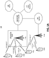
- the communications system 100 may include wireless transmit/receive units (WTRUs) 102a, 102b, 102c, and/or 102d (which generally or collectively may be referred to as WTRU 102), a radio access network (RAN) 103/104/105, a core network 106/107/109, a public switched telephone network (PSTN) 108, the Internet 110, and other networks 112, though it will be appreciated that the disclosed embodiments contemplate any number of WTRUs, base stations, networks, and/or network elements.
- Each of the WTRUs 102a, 102b, 102c, 102d may be any type of device configured to operate and/or communicate in a wireless environment.
- the WTRUs 102a, 102b, 102c, 102d may be configured to transmit and/or receive wireless signals and may include user equipment (UE), a mobile station, a fixed or mobile subscriber unit, a pager, a cellular telephone, a personal digital assistant (PDA), a smartphone, a laptop, a netbook, a personal computer, a wireless sensor, consumer electronics, and the like.
- UE user equipment
- PDA personal digital assistant
- smartphone a laptop
- netbook a personal computer
- a wireless sensor consumer electronics, and the like.
- the communications systems 100 may also include a base station 114a and a base station 114b.
- Each of the base stations 114a, 114b may be any type of device configured to wirelessly interface with at least one of the WTRUs 102a, 102b, 102c, 102d to facilitate access to one or more communication networks, such as the core network 106/107/109, the Internet 110, and/or the networks 112.
- the base stations 114a, 114b may be a base transceiver station (BTS), a Node-B, an eNode B, a Home Node B, a Home eNode B, a site controller, an access point (AP), a wireless router, and the like. While the base stations 114a, 114b are each depicted as a single element, it will be appreciated that the base stations 114a, 114b may include any number of interconnected base stations and/or network elements.
- the base station 114a may be part of the RAN 103/104/105, which may also include other base stations and/or network elements (not shown), such as a base station controller (BSC), a radio network controller (RNC), relay nodes, etc.
- BSC base station controller
- RNC radio network controller
- the base station 114a and/or the base station 114b may be configured to transmit and/or receive wireless signals within a particular geographic region, which may be referred to as a cell (not shown).
- the cell may further be divided into cell sectors.
- the cell associated with the base station 114a may be divided into three sectors.
- the base station 114a may include three transceivers, i.e., one for each sector of the cell.
- the base station 114a may employ multiple-input multiple output (MIMO) technology and, therefore, may utilize multiple transceivers for each sector of the cell.
- MIMO multiple-input multiple output
- the base stations 114a, 114b may communicate with one or more of the WTRUs 102a, 102b, 102c, 102d over an air interface 115/116/117, which may be any suitable wireless communication link (e.g., radio frequency (RF), microwave, infrared (IR), ultraviolet (UV), visible light, etc.).
- the air interface 115/116/117 may be established using any suitable radio access technology (RAT).
- RAT radio access technology
- the communications system 100 may be a multiple access system and may employ one or more channel access schemes, such as CDMA, TDMA, FDMA, OFDMA, SC-FDMA, and the like.
- the base station 114a in the RAN 103/104/105 and the WTRUs 102a, 102b, 102c may implement a radio technology such as Universal Mobile Telecommunications System (UMTS) Terrestrial Radio Access (UTRA), which may establish the air interface 115/116/117 using wideband CDMA (WCDMA).
- WCDMA may include communication protocols such as High-Speed Packet Access (HSPA) and/or Evolved HSPA (HSPA+).
- HSPA may include High-Speed Downlink Packet Access (HSDPA) and/or High-Speed Uplink Packet Access (HSUPA).
- the base station 114a and the WTRUs 102a, 102b, 102c may implement a radio technology such as Evolved UMTS Terrestrial Radio Access (E-UTRA), which may establish the air interface 115/116/117 using Long Term Evolution (LTE) and/or LTE-Advanced (LTE-A).
- E-UTRA Evolved UMTS Terrestrial Radio Access
- LTE Long Term Evolution
- LTE-A LTE-Advanced
- the base station 114a and the WTRUs 102a, 102b, 102c may implement radio technologies such as IEEE 802.16 (i.e., Worldwide Interoperability for Microwave Access (WiMAX)), CDMA2000, CDMA2000 IX, CDMA2000 EV-DO, Interim Standard 2000 (IS-2000), Interim Standard 95 (IS-95), Interim Standard 856 (IS-856), Global System for Mobile communications (GSM), Enhanced Data rates for GSM Evolution (EDGE), GSM EDGE (GERAN), and the like.
- IEEE 802.16 i.e., Worldwide Interoperability for Microwave Access (WiMAX)
- CDMA2000, CDMA2000 IX, CDMA2000 EV-DO Code Division Multiple Access 2000
- IS-95 Interim Standard 95
- IS-856 Interim Standard 856
- GSM Global System for Mobile communications
- GSM Global System for Mobile communications
- EDGE Enhanced Data rates for GSM Evolution
- GERAN GSM EDGERAN
- the base station 114b in FIG. 1A may be a wireless router, Home Node B, Home eNode B, or access point, for example, and may utilize any suitable RAT for facilitating wireless connectivity in a localized area, such as a place of business, a home, a vehicle, a campus, and the like.
- the base station 114b and the WTRUs 102c, 102d may implement a radio technology such as IEEE 802.11 to establish a wireless local area network (WLAN).
- the base station 114b and the WTRUs 102c, 102d may implement a radio technology such as IEEE 802.15 to establish a wireless personal area network (WPAN).
- WLAN wireless local area network
- WPAN wireless personal area network
- the base station 114b and the WTRUs 102c, 102d may utilize a cellular-based RAT (e.g., WCDMA, CDMA2000, GSM, LTE, LTE-A, etc.) to establish a picocell or femtocell.
- a cellular-based RAT e.g., WCDMA, CDMA2000, GSM, LTE, LTE-A, etc.
- the base station 114b may have a direct connection to the Internet 110.
- the base station 114b may not be required to access the Internet 110 via the core network 106/107/109.
- the RAN 103/104/105 may be in communication with the core network 106/107/109, which may be any type of network configured to provide voice, data, applications, and/or voice over internet protocol (VoIP) services to one or more of the WTRUs 102a, 102b, 102c, 102d.
- the core network 106/107/109 may provide call control, billing services, mobile location-based services, pre-paid calling, Internet connectivity, video distribution, etc., and/or perform high-level security functions, such as user authentication.
- the RAN 103/104/105 and/or the core network 106/107/109 may be in direct or indirect communication with other RANs that employ the same RAT as the RAN 103/104/105 or a different RAT.
- the core network 106/107/109 may also be in communication with another RAN (not shown) employing a GSM radio technology.
- the core network 106/107/109 may also serve as a gateway for the WTRUs 102a, 102b, 102c, 102d to access the PSTN 108, the Internet 110, and/or other networks 112.
- the PSTN 108 may include circuit-switched telephone networks that provide plain old telephone service (POTS).
- POTS plain old telephone service
- the Internet 110 may include a global system of interconnected computer networks and devices that use common communication protocols, such as the transmission control protocol (TCP), user datagram protocol (UDP) and the internet protocol (IP) in the TCP/IP internet protocol suite.
- the networks 112 may include wired or wireless communications networks owned and/or operated by other service providers.
- the networks 112 may include another core network connected to one or more RANs, which may employ the same RAT as the RAN 103/104/105 or a different RAT.
- the base stations 114a and 114b, and/or the nodes that base stations 114a and 114b may represent, such as but not limited to transceiver station (BTS), a Node-B, a site controller, an access point (AP), a home node-B, an evolved home node-B (eNodeB), a home evolved node-B (HeNB), a home evolved node-B gateway, and proxy nodes, among others, may include some or all of the elements depicted in FIG. 1B and described herein.
- BTS transceiver station
- Node-B a Node-B
- AP access point
- eNodeB evolved home node-B
- HeNB home evolved node-B gateway
- proxy nodes among others, may include some or all of the elements depicted in FIG. 1B and described herein.
- the transmit/receive element 122 may be configured to transmit signals to, or receive signals from, a base station (e.g., the base station 114a) over the air interface 115/116/117.
- a base station e.g., the base station 114a
- the transmit/receive element 122 may be an antenna configured to transmit and/or receive RF signals.
- the transmit/receive element 122 may be an emitter/detector configured to transmit and/or receive IR, UV, or visible light signals, for example.
- the transmit/receive element 122 may be configured to transmit and receive both RF and light signals. It will be appreciated that the transmit/receive element 122 may be configured to transmit and/or receive any combination of wireless signals.
- the transceiver 120 may be configured to modulate the signals that are to be transmitted by the transmit/receive element 122 and to demodulate the signals that are received by the transmit/receive element 122.
- the WTRU 102 may have multi-mode capabilities.
- the transceiver 120 may include multiple transceivers for enabling the WTRU 102 to communicate via multiple RATs, such as UTRA and IEEE 802.11, for example.
- the non-removable memory 130 may include random-access memory (RAM), read-only memory (ROM), a hard disk, or any other type of memory storage device.
- the removable memory 132 may include a subscriber identity module (SIM) card, a memory stick, a secure digital (SD) memory card, and the like.
- SIM subscriber identity module
- SD secure digital
- the processor 118 may access information from, and store data in, memory that is not physically located on the WTRU 102, such as on a server or a home computer (not shown).
- the processor 118 may receive power from the power source 134, and may be configured to distribute and/or control the power to the other components in the WTRU 102.
- the power source 134 may be any suitable device for powering the WTRU 102.
- the power source 134 may include one or more dry cell batteries (e.g., nickel-cadmium (NiCd), nickel-zinc (NiZn), nickel metal hydride (NiMH), lithium-ion (Li-ion), etc.), solar cells, fuel cells, and the like.
- the processor 118 may also be coupled to the GPS chipset 136, which may be configured to provide location information (e.g., longitude and latitude) regarding the current location of the WTRU 102.
- location information e.g., longitude and latitude
- the WTRU 102 may receive location information over the air interface 115/116/117 from a base station (e.g., base stations 114a, 114b) and/or determine its location based on the timing of the signals being received from two or more nearby base stations. It will be appreciated that the WTRU 102 may acquire location information by way of any suitable location-determination method while remaining consistent with an embodiment.
- the processor 118 may further be coupled to other peripherals 138, which may include one or more software and/or hardware modules that provide additional features, functionality and/or wired or wireless connectivity.
- the peripherals 138 may include an accelerometer, an e-compass, a satellite transceiver, a digital camera (for photographs or video), a universal serial bus (USB) port, a vibration device, a television transceiver, a hands free headset, a Bluetooth ® module, a frequency modulated (FM) radio unit, a digital music player, a media player, a video game player module, an Internet browser, and the like.
- the peripherals 138 may include an accelerometer, an e-compass, a satellite transceiver, a digital camera (for photographs or video), a universal serial bus (USB) port, a vibration device, a television transceiver, a hands free headset, a Bluetooth ® module, a frequency modulated (FM) radio unit, a digital music player, a media player, a video
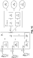
- FIG. 1C is a system diagram of the RAN 103 and the core network 106 according to an embodiment.
- the RAN 103 may employ a UTRA radio technology to communicate with the WTRUs 102a, 102b, 102c over the air interface 115.
- the RAN 103 may also be in communication with the core network 106.
- the RAN 103 may include Node-Bs 140a, 140b, 140c, which may each include one or more transceivers for communicating with the WTRUs 102a, 102b, 102c over the air interface 115.
- the Node-Bs 140a, 140b, 140c may each be associated with a particular cell (not shown) within the RAN 103.
- the RAN 103 may also include RNCs 142a, 142b. It will be appreciated that the RAN 103 may include any number of Node-Bs and RNCs while remaining consistent with an embodiment.
- the Node-Bs 140a, 140b may be in communication with the RNC 142a. Additionally, the Node-B 140c may be in communication with the RNC142b.
- the Node-Bs 140a, 140b, 140c may communicate with the respective RNCs 142a, 142b via an Iub interface.
- the RNCs 142a, 142b may be in communication with one another via an Iur interface.
- Each of the RNCs 142a, 142b may be configured to control the respective Node-Bs 140a, 140b, 140c to which it is connected.
- each of the RNCs 142a, 142b may be configured to carry out or support other functionality, such as outer loop power control, load control, admission control, packet scheduling, handover control, macrodiversity, security functions, data encryption, and the like.
- the core network 106 shown in FIG. 1C may include a media gateway (MGW) 144, a mobile switching center (MSC) 146, a serving GPRS support node (SGSN) 148, and/or a gateway GPRS support node (GGSN) 150. While each of the foregoing elements are depicted as part of the core network 106, it will be appreciated that any one of these elements may be owned and/or operated by an entity other than the core network operator.
- MGW media gateway
- MSC mobile switching center
- SGSN serving GPRS support node
- GGSN gateway GPRS support node
- the RNC 142a in the RAN 103 may be connected to the MSC 146 in the core network 106 via an IuCS interface.
- the MSC 146 may be connected to the MGW 144.
- the MSC 146 and the MGW 144 may provide the WTRUs 102a, 102b, 102c with access to circuit-switched networks, such as the PSTN 108, to facilitate communications between the WTRUs 102a, 102b, 102c and traditional land-line communications devices.
- the RNC 142a in the RAN 103 may also be connected to the SGSN 148 in the core network 106 via an IuPS interface.
- the SGSN 148 may be connected to the GGSN 150.
- the SGSN 148 and the GGSN 150 may provide the WTRUs 102a, 102b, 102c with access to packet-switched networks, such as the Internet 110, to facilitate communications between and the WTRUs 102a, 102b, 102c and IP-enabled devices.
- the core network 106 may also be connected to the networks 112, which may include other wired or wireless networks that are owned and/or operated by other service providers.
- FIG. ID is a system diagram of the RAN 104 and the core network 107 according to an embodiment.
- the RAN 104 may employ an E-UTRA radio technology to communicate with the WTRUs 102a, 102b, 102c over the air interface 116.
- the RAN 104 may also be in communication with the core network 107.
- the RAN 104 may include eNode-Bs 160a, 160b, 160c, though it will be appreciated that the RAN 104 may include any number of eNode-Bs while remaining consistent with an embodiment.
- the eNode-Bs 160a, 160b, 160c may each include one or more transceivers for communicating with the WTRUs 102a, 102b, 102c over the air interface 116.
- the eNode-Bs 160a, 160b, 160c may implement MIMO technology.
- the eNode-B 160a for example, may use multiple antennas to transmit wireless signals to, and receive wireless signals from, the WTRU 102a.
- Each of the eNode-Bs 160a, 160b, 160c may be associated with a particular cell (not shown) and may be configured to handle radio resource management decisions, handover decisions, scheduling of users in the uplink and/or downlink, and the like. As shown in FIG. ID, the eNode-Bs 160a, 160b, 160c may communicate with one another over an X2 interface.
- the core network 107 shown in FIG. ID may include a mobility management gateway (MME) 162, a serving gateway 164, and a packet data network (PDN) gateway 166. While each of the foregoing elements are depicted as part of the core network 107, it will be appreciated that any one of these elements may be owned and/or operated by an entity other than the core network operator.
- MME mobility management gateway
- PDN packet data network
- the MME 162 may be connected to each of the eNode-Bs 160a, 160b, 160c in the RAN 104 via an S1 interface and may serve as a control node.
- the MME 162 may be responsible for authenticating users of the WTRUs 102a, 102b, 102c, bearer activation/deactivation, selecting a particular serving gateway during an initial attach of the WTRUs 102a, 102b, 102c, and the like.
- the MME 162 may also provide a control plane function for switching between the RAN 104 and other RANs (not shown) that employ other radio technologies, such as GSM or WCDMA.
- the serving gateway 164 may be connected to each of the eNode-Bs 160a, 160b, 160c in the RAN 104 via the S1 interface.
- the serving gateway 164 may generally route and forward user data packets to/from the WTRUs 102a, 102b, 102c.
- the serving gateway 164 may also perform other functions, such as anchoring user planes during inter-eNode B handovers, triggering paging when downlink data is available for the WTRUs 102a, 102b, 102c, managing and storing contexts of the WTRUs 102a, 102b, 102c, and the like.
- the serving gateway 164 may also be connected to the PDN gateway 166, which may provide the WTRUs 102a, 102b, 102c with access to packet-switched networks, such as the Internet 110, to facilitate communications between the WTRUs 102a, 102b, 102c and IP-enabled devices.
- the PDN gateway 166 may provide the WTRUs 102a, 102b, 102c with access to packet-switched networks, such as the Internet 110, to facilitate communications between the WTRUs 102a, 102b, 102c and IP-enabled devices.
- the core network 107 may facilitate communications with other networks.
- the core network 107 may provide the WTRUs 102a, 102b, 102c with access to circuit-switched networks, such as the PSTN 108, to facilitate communications between the WTRUs 102a, 102b, 102c and traditional land-line communications devices.
- the core network 107 may include, or may communicate with, an IP gateway (e.g., an IP multimedia subsystem (IMS) server) that serves as an interface between the core network 107 and the PSTN 108.
- IMS IP multimedia subsystem
- the core network 107 may provide the WTRUs 102a, 102b, 102c with access to the networks 112, which may include other wired or wireless networks that are owned and/or operated by other service providers.
- FIG. IE is a system diagram of the RAN 105 and the core network 109 according to an embodiment.
- the RAN 105 may be an access service network (ASN) that employs IEEE 802.16 radio technology to communicate with the WTRUs 102a, 102b, 102c over the air interface 117.
- ASN access service network
- the communication links between the different functional entities of the WTRUs 102a, 102b, 102c, the RAN 105, and the core network 109 may be defined as reference points.
- the RAN 105 may include base stations 180a, 180b, 180c, and an ASN gateway 182, though it will be appreciated that the RAN 105 may include any number of base stations and ASN gateways while remaining consistent with an embodiment.
- the base stations 180a, 180b, 180c may each be associated with a particular cell (not shown) in the RAN 105 and may each include one or more transceivers for communicating with the WTRUs 102a, 102b, 102c over the air interface 117.
- the base stations 180a, 180b, 180c may implement MIMO technology.
- the base station 180a for example, may use multiple antennas to transmit wireless signals to, and receive wireless signals from, the WTRU 102a.
- the base stations 180a, 180b, 180c may also provide mobility management functions, such as handoff triggering, tunnel establishment, radio resource management, traffic classification, quality of service (QoS) policy enforcement, and the like.
- the ASN gateway 182 may serve as a traffic aggregation point and may be responsible for paging, caching of subscriber profiles, routing to the core network 109, and the like.
- the air interface 117 between the WTRUs 102a, 102b, 102c and the RAN 105 may be defined as an R1 reference point that implements the IEEE 802.16 specification.
- each of the WTRUs 102a, 102b, 102c may establish a logical interface (not shown) with the core network 109.
- the logical interface between the WTRUs 102a, 102b, 102c and the core network 109 may be defined as an R2 reference point, which may be used for authentication, authorization, IP host configuration management, and/or mobility management.
- the RAN 105 may be connected to the core network 109.
- the communication link between the RAN 105 and the core network 109 may defined as an R3 reference point that includes protocols for facilitating data transfer and mobility management capabilities, for example.
- the core network 109 may include a mobile IP home agent (MIP-HA) 184, an authentication, authorization, accounting (AAA) server 186, and a gateway 188. While each of the foregoing elements are depicted as part of the core network 109, it will be appreciated that any one of these elements may be owned and/or operated by an entity other than the core network operator.
- MIP-HA mobile IP home agent
- AAA authentication, authorization, accounting
- the MIP-HA may be responsible for IP address management, and may enable the WTRUs 102a, 102b, 102c to roam between different ASNs and/or different core networks.
- the MIP-HA 184 may provide the WTRUs 102a, 102b, 102c with access to packet-switched networks, such as the Internet 110, to facilitate communications between the WTRUs 102a, 102b, 102c and IP-enabled devices.
- the AAA server 186 may be responsible for user authentication and for supporting user services.
- the gateway 188 may facilitate interworking with other networks.
- the gateway 188 may provide the WTRUs 102a, 102b, 102c with access to circuit-switched networks, such as the PSTN 108, to facilitate communications between the WTRUs 102a, 102b, 102c and traditional land-line communications devices.
- the gateway 188 may provide the WTRUs 102a, 102b, 102c with access to the networks 112, which may include other wired or wireless networks that are owned and/or operated by other service providers.
- the RAN 105 may be connected to other ASNs and the core network 109 may be connected to other core networks.
- the communication link between the RAN 105 the other ASNs may be defined as an R4 reference point, which may include protocols for coordinating the mobility of the WTRUs 102a, 102b, 102c between the RAN 105 and the other ASNs.
- the communication link between the core network 109 and the other core networks may be defined as an R5 reference, which may include protocols for facilitating interworking between home core networks and visited core networks.
- Bandwidths available at above-6 GHz frequencies may be leveraged to achieve greater data rates and increased capacity.
- Various techniques may be considered to leverage the large bandwidths available at above-6 GHz frequencies, e.g., in order to meet the data rate (e.g., high data rate) that may be required for the next generation of cellular communication systems.
- the large bandwidth that may be available at these frequencies may provide substantial improvements for user-specific data transmission.
- one of the challenges of using the above-6 GHz frequencies may be the propagation characteristics that may be unfavorable for wireless communication, especially in an outdoor environment. For example, higher frequency transmissions may experience higher free space path loss. Rainfall and/or atmospheric gasses (e.g., oxygen) may add further attenuation, and foliage may cause attenuation and/or depolarization. Narrow beam patterns, which may be used to counter these losses, may pose challenges for a base station (e.g., eNB) in delivering cell-specific and/or broadcast information.
- a base station e.g., eNB
- mmW access link system design may focus on cellular systems that enable add-on mmW data transmission (e.g., at least downlink transmission) to an existing network, e.g., a small cell LTE network.
- a first network node may be a small Cell mmW eNB (SCmB).
- SCmB small Cell mmW eNB
- an LTE small cell eNB may be capable of operating an mmW air interface in parallel with an LTE air interface.
- the SCmB may transmit (e.g., simultaneously transmit) LTE downlink channels in a wide beam pattern and mmW channels in narrow beam patterns.
- the SCmB may support features and/or procedures in the LTE uplink operation, e.g., in order to support mmW UEs (mUEs) and/or mmW WTRUs (mWTRUs) without mmW uplink transmission.
- mUEs mmW UEs
- mWTRUs mmW WTRUs
- a second network node may be a mUE or an mWTRU.
- mUE and mWTRU may be terms that are used interchangeably herein.
- a WTRU may be capable of operating LTE and mmW air interface in parallel.
- the mWTRU may have two sets of antennas and/or the accompanied RF chains: one operating in the LTE band and/or the other in the mmW frequency band.
- a SCmB and/or an mWTRU may employ narrow beamforming.
- the SCmB and/or the mWTRU may employ narrow beamforming due to the high propagation loss (e.g., in NLOS at mmW frequency band).
- the SCmB and/or the mWTRU may employ narrow beamforming to provide sufficient link budget for high-throughput and/or low-latency data transmission.
- Transmit and receive narrow beam pairing may be provided.
- urban areas for example, at 28 GHz and/or 38 GHz, a consistent coverage with a cell-radius of up to 200 meters may be achieved using steerable 10°-beamwidth and 24.5-dBi horn antenna at the transmitter and the receiver.
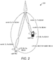
- FIG. 2 illustrates an exemplary SCmB deployment 200.
- the SCmB and the mWTRUs may apply broad beam pattern for the traditional LTE operation including cell search, random access, cell selection/reselection, etc.
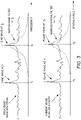
- the mWTRU receive beam forming may be regarded as a narrow spatial filtering, as illustrated in FIG. 3 .
- a comparison with frequency domain filtering is illustrated in FIG. 3 to demonstrate the effect of a spatial or angular filtering.
- spatial filtering may allow an mWTRU to detect a channel impulse response, e.g., at a distinct angular direction captured by the narrow receive beam. This may result in a flat effective channel by excluding angular incoming paths outside of the mWTRU's beam width.
- a WTRU e.g., a R12 LTE WTRU
- An aligned mmW transmit and receive beam pair may provide an additional degree of freedom in the angular domain, e.g., as compared with an LTE system.
- An mmW system (e.g., downlink system) design may focus on integrating directivity, e.g., the directivity of a narrow transmit and/or receive beam pair, into cellular system procedures. This may include layer one (LI) control signaling, data scheduling, narrow beam pairing, beam measurement, L1 control information feedback, etc.
- LI layer one
- Exemplary mmW system parameters and/or assumptions may be provided.
- the parameters and/or assumptions may change. These parameters and/or assumptions may not be intended to be limiting, but may serve to illustrate one or more possible set of parameters and/or assumptions of an example mmW system.
- An exemplary mmW system parameter and/or assumption may be carrier frequency. Carrier frequency may be 28 GHz (e.g., intended for an exemplary system numerology). The design may extend to other mmW frequencies, e.g., 38 GHz, 60 GHz, 72 GHz, etc.
- An example mmW system parameter and/or assumption may be system bandwidth. System bandwidth may be variable, e.g., up to 1 GHz with aggregation to higher bandwidth.
- An example mmW system parameter and/or assumption may be estimated RMS delay spread. Estimated RMS delay spread may be 100-200 ns with narrow beam pattern. An example mmW system parameter and/or assumption may be required latency (e.g., 1 ms). An example mmW system parameter and/or assumption may be waveform. Waveform may be OFDM-based and/or broad-band-single-carrier-based. An example mmW system parameter and/or assumption may be connectivity. Connectivity may be, e.g., LTE Small Cell eNB with mmW add-on channels, and/or two separate antennas and/or RF chains connected to two different antenna solutions.
- An example mmW system parameter and/or assumption may be data rates (e.g., DL minimum 30 Mbit/s, for at least 95% of mWTRUs).
- An example mmW system parameter and/or assumption may be mobility (e.g., optimized data connection at 3 km/h and/or maintain connection at 30 km/h).
- An example mmW system parameter and/or assumption may be coverage. Coverage may, for example, meet data rate and/or mobility requirements with less than 100-m cell radius.
- Frame structure for the system may depend on the applied waveform.
- a transmission time interval (TTI) length (e.g., 100 us) may be used, for example to achieve low latency.
- a system bandwidth (e.g., one in the range of 50MHz to 2GHz) may be used, for example, to achieve high data rates.
- the selection of the integer multiple K and/or the resulting ⁇ f may take into consideration the sensitivity to the Doppler shift, different types of frequency errors, and/or the ability to remove channel time dispersion.
- the orthogonality between sub-carriers may deteriorate and/or inter-sub-carrier interference may increase when the Doppler shift increases, e.g., in proportion to the sub-carrier spacing.
- the maximum Doppler shift at 30 km/h for 28 GHz may be 778 Hz.
- An example 28-GHz channel time dispersion measurement in a dense urban area may indicate that the RMS delay spread ⁇ may be between 100 and 200 ns (e.g., up to 200-m cell radius).
- the 90% coherence bandwidth may be estimated at 1/50 ⁇ of 100 kHz and/or the 50% coherence bandwidth at 1/5 ⁇ of 1 MHz.
- a sub-carrier spacing ⁇ f between 100 kHz and 1 MHz may be reasonable.
- the corresponding symbol length (1/ ⁇ f) may be 3.33 us.
- a cyclic prefix (CP) length may span over a length (e.g., the entire length) of the channel time dispersion, e.g., in order to attempt to eliminate the inter-symbol-interference.
- a long CP may cause excessive system overhead, e.g., as a CP does not carry useful data.
- An example of CP length for a T symbol of 3.33 us may be selected at 1/14 of T symbol , 0.24 us and/or the corresponding CP overhead may be 7%, as calculated by T CP / (T CP + T symbol ).
- TTI length of an mmW transmission may be reduced (e.g., reduced significantly) compared to the 1-ms TTI length of the LTE system.
- the TTI length may be reduced to achieve low latency.
- An mmW sub-frame length of 1 ms may be used to align with the LTE 1-ms sub-frame timing.
- the mmW sub-frame may include multiple mmW TTIs.
- the length the mmW TTIs may be tied to one or more parameters including for example, sub-carrier spacing, symbol length, CP length, FFT size, etc.
- FIG. 4 illustrates an exemplary frame structure 400 corresponding to the example disclosed in Table 1.
- the system bandwidth may be 1GHz, and/or a sub-carrier spacing of 300 kHz, with a corresponding symbol length of 3.33 us, may be used.
- An example cyclic prefix (CP) length of 1/4 of T symbol which equals 0.833 us may be used.
- the frame structure may assume an OFDM-based mmW waveform, which may be incorporated into the OFDM-based LTE small cell network.
- the system procedure design proposed may not be bound by this frame structure and/or may be applied to other waveform candidates.
- mmW physical channels may be provided.
- a SCmB deployment may employ mmW physical layer channels and/or reference signals, as described herein, in addition to the LTE physical channels.
- beam-specific reference signal BSRS
- BSRS beam-specific reference signal
- a unique sequence transmitted per transmit beam may be used for beam acquisition, timing/frequency synchronization, channel estimation for a physical downlink directional control channel (PDDCCH), beam tracking and measurement, etc.
- PDDCCH physical downlink directional control channel
- a beam-specific reference signal may carry (e.g., implicitly carry) beam identity beam information.
- the beam identity information may include a BSRS sequence index.
- Different types of BSRSs may be provided.
- the BSRS resource allocation may be pre-defined.
- An adaptive antenna reference signal may be employed.
- a sequence e.g., a unique sequence
- the sequence may be scheduled and/or transmitted dynamically.
- the sequence may be scheduled and/or transmitted for beam pair measurement associated with an antenna port.
- An adaptive antenna reference signal may have embedded (e.g., implicitly embedded) beam identity information.
- the beam identity information may be in the sequence index and/or may carry a small payload, e.g., a small payload including the same information.
- a physical downlink directional control channel may be employed.
- a PDDCCH may carry data (e.g., all data) related to control information.
- the control information may be for an mWTRU to identify, demodulate, and/or decode the associated PDDDCH correctly.
- the PDDCCH may be carried in an mmW narrow beam and/or in a broad beam.
- the PDDCCH may apply different multiple access. For example, a common PDDCCH transmitted may be transmitted in downlink mmW broad beam covering a sector and/or cell and/or a dedicated PDDCCH transmitted (e.g., only transmitted) in a narrow beam pair, e.g., when mWTRU-specific data is transmitted.
- the dedicated PDDCCH may carry scheduling information, e.g., for its associated PDDDCH.
- the dedicated PDDCCH may be carried on a per-TTI basis.
- a PDDCCH (e.g., a common PDDCCH) may include cell-specific information, e.g., sector/segment identity and/or beam identity.
- An mWTRU may determine from the common PDDCCH whether it is scheduled, e.g., for a narrow beam pairing procedure, e.g., to begin a narrow beam data transmission.
- a physical downlink directional data channel may be employed.
- the PDDDCH may carry payload information.
- the payload information may be received as a medium access control protocol data unit (MAC PDU), e.g., from the mmW MAC layer.
- the resource allocation (e.g., complete resource allocation) of this channel may be determined by the downlink scheduling information, e.g., the downlink scheduling information carried in PDDCCH.
- the PDDDCH intended for an mWTRU may be transmitted in a narrow Tx beam and/or received in a properly paired narrow Rx beam, e.g., a narrow beam pair.
- PDDDCHs for different WTRUs in different beam pairs may reuse time, frequency, and/or code resources, for example, due to spatial isolation. Multiple PDDDCHs may operate in one transmit/receive beam pair using multiple access in time, frequency, and/or code domain.
- a common PDDDCH may be used to carry data.
- a common PDDDCH may be used to carry data in broad mmW antenna pattern associated with the common PDDCCH.
- DMRS Demodulation reference signal
- symbols may be embedded in the transmission for channel estimation for PDDDCH.
- the signals may be placed in time and/or frequency domain (e.g., both time and frequency domain).
- the signals may be placed according to a pre-defined pattern, for example, for correct interpolation and/or reconstruction of the channel.
- One or more of channels and/or reference signals in a narrow beam pair may be beamformed (e.g., beamformed identically) and/or considered to be transmitted via a physical antenna port. Carrying broadcast and/or multicast information may not be an optimal application, e.g., given the directivity of the transmission of the channels.
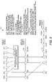
- the SCmB deployment with mmW downlink data transmission may adopt a channel mapping (e.g., as illustrated in FIG. 5).
- FIG. 5 illustrates an example downlink logical, transport, and physical channels in an mmW system 500.
- the mmW channels in FIG. 5 are channels downlink directional data channel (DL-DDCH) 502, physical downlink directional data channel (PDDDCH) 504, and physical downlink directional control channel (PDDCCH) 506.
- DL-DDCH downlink directional data channel
- PDDDCH physical downlink directional data channel
- PDDCCH physical downlink directional control channel
- An mWTRU Beamforming may be provided.
- An mWTRU may use a phase antenna array to achieve beamforming gain.
- the beamforming gain may be used to compensate high path loss at mmW frequencies, at which the short wavelength allows a compact form factor of a device design.
- An element spacing of 0.5 ⁇ may be used.
- a large element spacing, for example, an element spacing of 0.7 ⁇ may be used.
- the phase antenna may apply different beamforming algorithms.
- a digitized beamforming approach for example, for each antenna element, may have an RF chain, for example, a dedicated RF chain, an RF processing unit and/or an ADC.
- the signal processed by an antenna element may be controlled (e.g., controlled independently) in phase and/or amplitude.
- the signal processing may be controlled, for example, to optimize the channel capacity.
- a configuration may have one or more RF chains.
- the number of ADCs may be same as the number of antenna elements. While offering very high performance, the mWTRU antenna configuration may impose a cost (e.g., a high cost) and/or complexity in implementation and/or cause high energy consumption in operation.
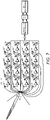
- FIG. 7 illustrates an example of mWTRU analog beamforming with one phase antenna array (PAA) and one radio frequency (RF) chain.
- Terms analog and analogue may be used interchangeably.
- a practical approach e.g., analogue beamforming
- An antenna element e.g., each antenna element
- the number of RF chains (e.g., required number of RF chains) and/or the energy consumption may be reduced (e.g., significantly reduced).
- the phase of the signal at antenna elements may be adjusted.
- the phase shifting and/or combining may be implemented in one or more stages including, for example, RF stage, baseband (BB) analog circuit stage, or local oscillator (LO) stage.
- BB baseband
- LO local oscillator
- Each implementation may be evaluated in terms of signal loss, phase error, power consumption, etc.
- the mWTRU analog beamforming algorithms may include fixed codebook-based beamforming and/or continuous phase shifting beamforming.
- Fixed codebook-based beamforming may include a grid of beams comprising a set of fixed beams. Each beam may be formed by the mWTRU, e.g., an mWTRU applying a beamforming weight vector v chosen from a pre-defined codebook v ⁇ ⁇ v 1 , v 2 , v 3 ... v N ⁇ , where N may denote the number of fixed beams.
- Vectors may include pre-calibrated phase shifts for phase shifters (e.g., all phase shifters) and/or may represent a unique analogue beam direction, e.g., a beam.
- the number of beams may depend on the half-power-beam-width (HPBW) of the beamforming and the desired coverage.
- the mWTRU analog beamforming algorithms may include continuous phase shifting beamforming.
- the weight (e.g., desired weight) of a phase shifter e.g., each phase shifter
- DAC digital-to-analog converter
- Continuous phase shifting beamforming may provide a continuous and/or adaptive beamforming, for example, to track the channel conditions.
- the algorithm may perform well in scenarios with increased multipath, high angular spread, and/or low WTRU mobility.
- System parameters e.g., basic system parameters
- the hybrid beamforming may include one or more data streams (N DATA ), one or more RF chains (TRX) (N TRX ), one or more antenna ports (N AP ), one or more antenna elements (N AE ), and/or one or more phase antenna arrays (N PAA ).
- the configuration of these parameters may impact the system function and/or performance, as described herein.
- N PAA ⁇ N AP ⁇ N TRX ⁇ N AE a phase antenna array (PAA) (e.g., one PAA) may include multiple antenna elements.
- PAA phase antenna array
- An antenna port may be defined such that the channel over which a symbol on the antenna port may be conveyed may be inferred from the channel over which another symbol on the same antenna port may be conveyed.
- One or more resource grids per antenna port may be provided.
- MBSFN multicast-broadcast single-frequency network
- An LTE based (e.g., an LTE R12 based) antenna port configuration may include WTRU-specific reference signals associated with PDSCH.
- An LTE (e.g., an LTE R12) antenna port configuration may include demodulation reference signals, e.g., demodulation reference signals associated with EPDCCH transmitted on one or more of p ⁇ ⁇ 107,108,109,110 ⁇ .
- LTE (e.g., an LTE R12) antenna port configuration may include CSI reference signals.
- An antenna port may carry a beamformed reference signal.
- a beamformed reference signal associated with the antenna port.
- the beamformed reference signal may be used to identify the antenna port.
- the antenna configuration may become a digitalized solution (e.g., fully digitized solution) as shown in FIG. 7 , e.g., when the number of TRX equals the number of antenna elements (e.g., one RF chain per antenna element).
- This configuration may allow a spatial independence between the two simultaneous beams, e.g., by placing the PAAs at different orientation (e.g., in the azimuth plane).
- An aligned PAA arrangement may provide an aggregated larger coverage compared to the configuration in FIG. 8 .
- Configurations (e.g., both configurations with two RF chains) may apply MIMO with two data streams.
- multiple PAAs may be connected to an RF chain (e.g. a single RF chain), e.g., by using a switch, as illustrated in FIG. 10 .
- Each of the PAAs may form a narrow beam pattern covering from +45° to -45° in azimuth plane.
- the narrow beam patterns may be oriented (e.g., oriented separately) so a single-beam solution may provide a good coverage, e.g., by using a narrow beam at different directions at different time instances.
- an mWTRU may have a single-beam configuration and/or may operate one beam at a time.
- the mWTRU beamforming may form the narrow beam pattern, such as the one shown in FIG. 11 , e.g., for a 16x16 PAA at the strongest angular direction, e.g. a line of sight (LOS) path obtained from beam measurement.
- the mWTRU may form a broad beam pattern (e.g., a wide main lobe), such as the one shown in FIG. 12 , e.g., to cover a range of continuous angular directions including both strong and weak angular directions in-between.
- the antenna gain may be reduced with a broad beam pattern, and the link budget may become worse.
- an mWTRU may have one or more (e.g., two) beam patterns (e.g., simultaneous beam patterns) and/or the beam patterns may be different and/or may be used for different applications.
- the mWTRU may place narrow beam patterns (e.g., two narrow beam patterns) at different angular incoming directions, e.g., to receive one or more (e.g., one) data streams.
- coherent beam combining may be used to utilize the spatial diversity and/or mitigate the blockage effect and/or weak LOS condition.
- the mWTRU may form one or more narrow beams and/or one or more broad beams, e.g., for different applications.
- the narrow beam may be used for data transmission and/or the broad beam may be used for control signaling.
- the transmission may apply MIMO to increase the capacity (e.g., in high SNR channel conditions).
- the mWTRU may place narrow beam patterns (e.g., two narrow beam patterns) at different angular incoming directions to receive two data streams in parallel.
- the SCmB beam forming schemes may include fixed beam, adaptive beam forming (e.g., codebook-based and/or non-codebook-based), and/or classical beam forming (e.g., Direction-of-Arrival (DoA)) estimation.
- the schemes e.g., each scheme
- the DoA estimation may require smaller angular spread and/or an mWTRU may transmit an LTE uplink reference signal to provide DoA accuracy.
- the fixed beam system may have beam cycling and/or switch procedures.
- the mWTRU antenna configuration and/or beamforming discussed herein may be based on a single-beam mWTRU antenna configuration, e.g., with analog beamforming, as illustrated in FIG. 7 .
- a beam may be one of the lobes, e.g., main/side/grating lobes of the transmit radiation pattern and/or receive gain pattern of an antenna array.
- a beam may denote a spatial direction, for example represented by a set beamforming weights.
- a beam may be identified and/or associated with one or more of a reference signal, an antenna port, a beam identity (ID), a scrambling sequence number.
- the beam may be transmitted and/or received at a specific time and/or frequency using a code and/or spatial resources.
- a beam may be formed digitally, in an analog manner, and/or both (e.g., hybrid beamforming). The analog beamforming may be based on fixed code-book or continuous phase shifting.
- a data channel beam may be used to transmit data channel, data channel beam, PDSCH, mPDSCH, mmW PDSCH, mmW data channel, directional PDSCH, beamformed data channel, spatial data channel, data channel slice, and/or high frequency data channel.
- a data channel beam may be identified and/or associated with a reference signal, an antenna port, a beam identity (ID), a scrambling sequence number, and/or may be transmitted and/or received at a specific time and/or frequency using a code and/or spatial resources.
- mB, SCmB, eNB, cell, small cell, Pcell, Scell may be used interchangeably.
- Operate may be used interchangeably, e.g., with transmit and/or receive.
- Component carrier and/or mmW carrier may be used interchangeably, e.g., with serving cell.
- a channel may refer to a frequency band which may have a center or carrier frequency and/or a bandwidth. Spectrum may include one or more channels which may or may not overlap. Channel, frequency channel, wireless channel, and/or mmW channel may be used interchangeably. Accessing a channel may be the same as using (e.g., transmitting over and/or receiving on) the channel.
- a channel may refer to an mmW channel and/or signal, e.g., an uplink channel and/or signal, and a downlink physical channel and/or signal.
- Downlink channels and signals may include one or more of: a mmW synchronization signal, a mmW broadcast channel, a mmW cell reference signal, a mmW beam reference signal, a mmW beam control channel, a mmW beam data channel, a mmW hybrid ARQ indicator channel, a mmW demodulation reference signal, a primary synchronization signal (PSS), a secondary synchronization signal (SSS), a demodulation reference signal (DMRS), cell-specific reference signal (CRS), channel state information-reference signal (CSI-RS), a physical broadcast channel (PBCH), a physical downlink control channel (PDCCH), a physical hybrid ARQ indicator channel (PHICH), an enhanced physical downlink control channel (EPDCCH), and/or a physical downlink shared channel (PDSCH).
- PBCH primary synchronization
- Uplink channels and signals may include one or more of mmW physical random access channel (PRACH), mmW control channel, mmW data channel, mmW beam reference signal, mmW demodulation reference signal, PRACH, physical uplink control channel (PUCCH), a sounding reference signal (SRS), a demodulation reference signal (DMRS), and/or a physical uplink shared channel (PUSCH).
- PRACH physical random access channel
- mmW control channel mmW data channel
- mmW beam reference signal mmW demodulation reference signal
- PRACH physical uplink control channel
- PUCCH physical uplink control channel
- SRS sounding reference signal
- DMRS demodulation reference signal
- PUSCH physical uplink shared channel
- PRACH and/or preamble may be used interchangeably.
- Data/control may mean data and/or control signals and/or channels. Control may include synchronization.
- the data/control may be mmW data/control. Data/control and data/control channels and/or signals may be used interchangeably. Channels and/or signals may be used interchangeably.
- the terms control channel, control channel beam, PDCCH, mPDCCH, mmW PDCCH, mmW control channel, directional PDCCH, beamformed control channel, spatial control channel, control channel slice, and/or high frequency control channel may be used interchangeably.
- the terms data channel, data channel beam, PDSCH, mPDSCH, mmW PDSCH, mmW data channel, directional PDSCH, beamformed data channel, spatial data channel, data channel slice, and/or high frequency data channel may be used interchangeably.
- mmW beam reference signal mmW reference resource for beam measurement, mmW measurement reference signal, mmW channel state measurement reference signal, mmW demodulation reference signal, mmW sounding reference signal, reference signal, CSI-RS, CRS, DM-RS, DRS, measurement reference signal, reference resource for measurement, CSI-IM, and/or measurement RS may be used interchangeably.
- mmW cell, mmW small cell, SCell, secondary cell, license-assisted cell, unlicensed cell, and/or LAA cell may be used interchangeably.
- mmW cell, mmW small cell, PCell, primary cell, LTE cell, and/or licensed cell may be used interchangeably.
- a WTRU may determine the UL and/or DL directions of one or more subframes, e.g., according to one or more received and/or configured TDD UL/DL configurations.
- UL/DL and UL-DL may be used interchangeably.
- Transmit power, power, and/or antenna array transmit power may be used interchangeably.
- cmW and/or mmW may be used interchangeably.
- the throughput of wireless communication systems has increased significantly, e.g., by new technologies introduced in LTE and Wi-Fi. These technologies may not be sufficient to meet the demands of future applications which, e.g., may require Gbits/sec of throughput and latencies of 1 ms.
- One of the components of new radio or the 5G radio access technology may be the radio waveform.
- Orthogonal frequency division multiplexing (OFDM) has been used for LTE and/or Wi-Fi, e.g., due to its simplicity in converting a frequency selective channel into smaller flat fading sub channels (e.g., allowing one-tap equalization per subchannel).
- Discrete Fourier transformation-spreading-orthogonal frequency division multiplexing may improve the peak average power rate (PAPR) of an OFDM transmission.
- DFT-S-OFDM may spread the data sequence with DFT before loading the spread signal onto the subchannels.
- CP sizes may not be feasible for a fixed sub-frame duration, e.g., because changing the cyclic prefix size would change the number of OFDM symbols in a subframe.
- waveforms such as zero tail (ZT) DFT-s-OFDM and unique word (UW) OFDM have may be provided, for example, to address the limitation posed by the CP.
- the zero tail based waveforms may decouple the numerology from the channel characteristics.
- the zero tail duration may be dynamically adapted to the channel delay spread. For example the zero tail duration may be adapted without changing the OFDM symbol duration.
- the zero tail may be used as a gap for beam switching, DL/UL switching, and/or interference measurement in mmWave channels.
- FIG. 13 illustrates an example of a ZT DFT-s-OFDM transmitter.
- the zero tail may be generated by feeding zeros to the head 1302 and/or tail 1304 of the DFT spreading block.
- the size of the DFT block 1306 is M and the IFFT block 1308 is N_IFFT, at the output of the IFFT, there may be the M data symbols and (NIFFT/M -1) interpolated samples between each data symbol.
- the zero inputs to the DFT block may be distributed on the head and/or tail of the signal, e.g., at the output of the IFFT.
- the tail may not become zero (e.g., exactly zero) due to the interpolated samples.
- the zero tail may be different from one DFT-s symbol to the next, e.g., because the interpolated samples may be data dependent.
- the cyclic property may not be preserved, which may lead to a bit error floor at high SNR, for example in case of high order modulations.
- the shortcomings of the ZT DFT-s OFDM signal may include, e.g., the non-perfect zero tail breaking the cyclic property of the OFDM signal and/or creating ISI. This may result in a BER floor at high SNR, e.g., in high delay spread channels.
- a flexible waveform framework may be provided to address the shortcomings of existing ZT waveform, such as elimination of error floor for ZT DFT-s OFDM, improve the BER performance, enable cyclicity of signal, mitigate power spike in the tail, etc., while enabling very low-complexity and low-cost implementation.
- Waveform systems may be provided that may change (e.g., dynamically change) the guard interval duration, e.g., to support channel delay spreads (e.g., different channel delay spreads) without changing the numerology, symbol duration, and/or subcarrier spacing.
- a waveform and/or system may be designed and/or optimized for indoor LOS focus and with additional capabilities, e.g., for NLOS handling and/or outdoor extension.
- a flexible support for frequency domain scheduling and multi-user multiplexing may be provided.
- a flexible and/or universal framework may be provided that may support the hybrid-s-OFDM waveforms, e.g., with extension to cover other alternative designs.
- a waveform system may combine a cyclic prefix (CP) and a low power tail (LPT), where a fixed CP may consist of low power CP (LPCP).
- the waveform system may utilize a hybrid guard interval (HGI).
- the HGI may include a fixed short LPCP and/or an adaptive LPT.
- the adaptive LPT may be used for ISI handling.
- a low power cyclic prefix may be generated from low power tail (LPT).
- LPT low power tail
- the LPT may be generated, e.g., using a zero tail (ZT) technique, or the like.
- ZT zero tail
- the length of LPT may be at least equal to the delay spread.
- Waveform systems may be provided to change (e.g., dynamically change) the hybrid guard interval (HGI) to support different channel delay spreads without changing the numerology, symbol duration, and subcarrier spacing.
- HGI hybrid guard interval
- a waveform and/or system may be designed and/or optimized for indoor LOS focus, e.g., using a fixed prefix, suffix, and/or CP, and with additional capabilities for non-line of sight (NLOS) handling and/or outdoor extension, e.g., using adaptive low power tail (LPT).
- NLOS non-line of sight
- LPT adaptive low power tail
- the waveform and/or systems provided may include one or more of the following:
- the waveform and/or system may enable overhead (e.g., significant overhead) reduction, improved performance, and/or energy efficiency.
- Waveform overhead reduction may enable a setting (e.g., an aggressive setting) for a fixed CP utilizing a short CP length, for example, optimized for indoor LOS focus.
- Waveform overhead reduction may enable cyclicity of the signal (e.g., due to use of CP), and may reduce or eliminate zero head to generate low power tail or zero tail (e.g., additional overhead reduction with respect to the use of ZT).
- Improved performance may enable use of fixed CP at higher SNR to improve performance, and may mitigate power regrowth and/or power spike in the tail, as compared to the ZT solutions.
- Short CP portion e.g., with extremely low power may result in energy efficiency.
- the waveform solution and/or system may enable seamless configuration switching. Seamless switching between CP and ZT waveforms may be possible, e.g., due to same numerology (same symbol duration, same FFT window size, same subcarrier spacing, etc.) for systems. Configuration switching may be easier.
- a hybrid-s-OFDM waveform system may be provided that may combine the conventional fixed waveform (e.g., using a fixed prefix or suffix) with a non-conventional adaptive waveform.
- Systems, methods, and instrumentalities may be provided to implement low power cyclic prefix (LPCP) and low power tail (LPT).
- Hybrid-s-OFDM waveform may combine (e.g., intelligently combine) a non-adaptive fixed prefix and/or a suffix, and an adaptive low power tail waveform components.
- a hybrid-s-OFDM waveform may combine a non-adaptive waveform component (e.g., a CP) and/or an adaptive low power tail (e.g., ZT).
- the hybrid spread waveform may manage one or more channels by, for example, using a prefix and/or a CP in some cases and/or a LPT in other cases.
- a fixed prefix, suffix, and/or CP e.g., may be utilized to handle channel conditions that, for example, are optimized for indoor LOS.
- Adaptive part of the waveform may be triggered by utilizing an LPT.
- the utilization of an LPT may be utilized to handle delay spread channels, for example, channels with longer delay spread in an NLOS and/or outdoor channel condition.
- FIG. 14 illustrates an example of a hybrid spread waveform 1400 utilizing a fixed prefix and adaptive low power tail (LPT).
- LPT adaptive low power tail
- a prefix may be a CP.
- a LPT may be generated using ZT technique. Though the hybrid waveform is described herein utilizes a CP and a ZT waveform, those skilled in the art can recognize that other adaptive waveforms may be utilized to generate an LPT.
- Low power prefix and/or low power CP may be adopted to, e.g., reduce the power consumption of waveform and/or enhance energy efficiency of waveform and/or system.
- Low power CP may be used to enable cyclicity of signal and/or mitigate the power regrowth of the tail that may occur in the ZT DFT-s OFDM systems.
- the hybrid-s-OFDM may utilize DFT and/or FFT spreading for data.
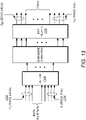
- FIG. 15 illustrates an example of a hybrid-s-OFDM with LPCP and LPT generation using ZT.
- data 1502 may be spread, e.g., using FFT 1504 (or DFT).
- a LPT may be generated using ZT technique.
- ZT may be a low complexity technique, e.g., to generate low power tail.
- zeros may be inserted in the input of FFT 1504 (and/or DFT).
- low power CP LPCP
- the LPCP may be added to the output of IFFT 1508.
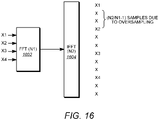
- FIG. 16 illustrates an example of zero insertion and interpolation.
- a low power tail may be produced by zero insertion (e.g., at input of an FFT 1602) and/or interpolation (e.g., at output of an IFFT 1604).
- the low power tail may be produced by using ZT.
- the use of ZT may result in loss of cyclicity, as illustrated in FIG. 17 . This may be because, e.g., Ax ⁇ ⁇ y in the tail for two adjacent symbols Data11 1702 and Data12 1704. To enable cyclicity of the signal, ⁇ x may be equal to ⁇ y.
- Hybrid-s-OFDM waveform may overcome the cyclicity issue, e.g., by utilizing a LPCP generated from Ax and ⁇ y .
- a LPCP may be generated using ⁇ x
- a LPCP may be generated using ⁇ y.
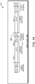
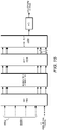
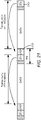
- an LPCP may be equal to ⁇ x for Data11 and a LPCP may be equal to ⁇ y for Data 12. This is further illustrated in FIG. 18 .
- a hybrid guard interval (HGI) 1806 may include a fixed CP 1804 (where a CP may be an LPCP) and an adaptive low power tail (LPT) 1802.
- LPCP 1804 may enable the cyclicity of a signal, e.g., between adjacent symbols 1814 and 1810 for hybrid-s-OFDM.
- the hybrid-s-OFDM based waveform may be more efficient, for example, than the fixed CP based waveform. The efficiency may be because the tail length may be adapted (e.g., dynamically adapted) to the channel conditions or the delay spread.
- FIG. 18 A comparison of the fixed-CP based waveform and the HGI-based waveform is illustrated in FIG. 18 .
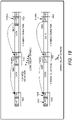
- FIG. 19 illustrates an example of a hybrid-s-OFDM system maintaining same numerology (e.g., same symbol duration, FFT window size, subcarrier spacing, etc.) for different delay spreads.
- a short LPT 1904 may be used, e.g., if delay spread is short (e.g., in a LOS condition).
- Long LPT 1902 may be used, e.g., if delay spread is long (e.g., in a NLOS condition).
- LPT may be shortened and/or enlarged (e.g., dynamically shortened and/or enlarged), e.g., to accommodate different delay spreads and/or propagation delays, e.g., based on the changing channel environment.
- explicit signaling may carry information (e.g., rough information) about the number of inserted zeros and/or LPT (HGI) length (e.g., the range of zeros and/or the length) and/or rely on method (e.g., an implicit method, such as blind detection) to further narrow down and/or accurately detect the number (e.g., the exact number) of zeros and/or the length of LPT (and/or HGI).
- HGI LPT
- LPCP low power cyclic prefix
- an LPCP may be utilized.
- the LPCP may reduce energy consumption and/or achieve energy efficient waveform.
- the LPCP waveform may utilize low (e.g., extremely low) power, e.g., whose power level is below (e.g., significantly well below) the power level of data part (e.g., 15 - 20dB or more below the data power level), regardless of the power level of the data part.
- LPT may be generated using ZT.
- LPCP may be generated using the LPT.
- LPCP may be designed to enable cyclicity of LPT.
- LPCP may be designed to mitigate power spike in low power tail.
- LPT may be generated, e.g., without using zero head.
- LPT may be generated using delay spread as input and LPCP as threshold.
- Low power CP may be generated as follows.
- Low power CP (LPCP) may be generated by determining the length of LPCP, L_LPCP.
- L_LPCP may consider delay spread and/or power regrowth.
- L_LPCP may be determined based on the length of majority delay spread and/or power regrowth.
- LPCP may be fixed throughout the system, e.g., once LPCP length is determined.
- L_LPCP may be equal to max (Ld, Lp), where Ld may be the length of majority delay spread, and Lp may be the length of power regrowth. Ld may be greater than Lp.In an example design L_LPCP may be equal to, but not limited to Ld.
- LPT Low power tail
- L_LPT may be generated, e.g., once L_LPCP is determined.
- LPT may be generated, e.g., based on a delay spread, using LPCP length as a threshold.
- An example symbol structure is illustrated in the FIG. 20-1 . As illustrated in FIG. 20-1 , the data in the DFT window may have two parts: Data 1 2002 and Data 2 2004.
- Each zero fragment may have length equal to (delay spread) - L LPCP.
- the spectral efficiency may be enhanced, e.g., because Data 2 2004 may carry data instead of zeros. If the delay spread ⁇ L LPCP, no LPT may be generated. If the delay spread > L_LPCP, two zero fragments may be generated.
- FIG. 20-3 illustrates an example of creating two fragments of zeros.
- the two zero segments may be close to, but not exactly zeros, e.g., due to the interpolation nature in the output of the IFFT module.
- the LPT length may be determined (e.g., determined first).
- N_t may be determined (e.g., determined next).
- the low power CP (LPCP) waveform (e.g., the final low power CP (LPCP) waveform) may be generated.
- LPT may be generated at the output of IFFT.
- LPCP may be generated, e.g., by taking the last L_LPCP portion of LPT, e.g., the last L_LPCP portion of LPT that is equal to the length of LPCP.
- the LPT copy (e.g., the LPT copy having LPCP length) may be inserted to the front of waveform before data. Transmit LPCP and data with LPT (e.g., both LPCP and data with LPT).
- the HGI length (e.g., total HGI length) may be equal to LPCP length + LPT length.
- Hybrid-s-OFDM may include LPCP.
- the LPCP may be generated using one or more ZT techniques.
- FIG. 21 illustrates an example of low power CP waveform generation for a hybrid-s-OFDM based system.
- the LPCP 2102 may be generated from LPT 2104, e.g., using ZT technique.
- d N h ⁇ 1 may be a vector of size N h ⁇ 1 which may carry zeros and/or data.
- FIGs. 22 and 23 illustrate examples of low power tail (LPT) generation using ZT technique in hybrid-s-OFDM systems.
- d Nh ⁇ 1 may carry data.
- d N h ⁇ 1 may carry zeros. Since one or more of the designs may not need d N h ⁇ 1 to carry zeros, d Nh ⁇ 1 may be used to carry data (e.g., which may reduce waveform overhead and/or enhance spectrum efficiency).
- d Nh ⁇ 1 may be used to carry certain control information (e.g., waveform configuration switch indicator (Switch_IND)) as described herein.
- y d [ y 0 y 1 ...
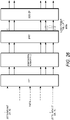
- FIG. 24 illustrates an example of configuration switching in a hybrid-s-OFDM system.
- a LPT may utilize a ZT
- CP may be a LPCP.
- Dynamic switching between CP and/or ZT may be performed.
- the CP and ZT configurations may be switched seamlessly.
- the system may switch to CP-based waveform (CP configuration), for example, when the system is in a LOS condition.
- the system may switch to ZT-based waveform (ZT configuration), for example, when the system is in an NLOS condition.
- CP configuration CP-based waveform
- ZT configuration ZT-based waveform
- a switch indicator (e.g., Switch_IND) may be sent from eNodeB (eNB), an access point (AP) and/or a network to a user.
- the switch indicator may indicate to the user switch the configuration.
- the configuration switching may not change numerology, e.g., symbol duration, FFT window size, subcarrier spacing, and/or any other system parameters.
- Switching may be performed dynamically, e.g., using a fast control channel, either a layer one control or MAC, and/or semi-statically using higher layer signaling.
- the user may decode the control channel, obtain the Switch_IND.
- the user may switch to the proper configuration according to the content of Switch_IND.
- Seamless switching may increase system flexibility. Seamless switching may make resource scheduling more efficient. The switching may be performed on per-user basis, per TTI-basis, and/or a combination of per-user basis and per TTI-basis. For example, in a case of per-user based basis, one user may be configured for and operating on CP configuration and another user may be configured for and operating on ZT configuration.
- configurations may be dynamically switched between CP and ZT.
- CP may be configured and/or used in TTI# x.
- ZT may be configured and/or used in TTI# y.
- Different user groups may be configured and/or operating in different configurations, e.g., when applying to a per-user group basis.
- the users in a group e.g., the same group
- WTRU group A may be configured and/or operating with ZT
- WTRU group B may be configured and/or operating with CP.
- Different beams may be configured and/or operating in different configurations, e.g., when applying to per-beam basis for beamforming system. Users in the same beam may use and/or operate in the same configuration. For example, beam# 1 may be configured and/or operating with ZT, while beam# 2 may be configured and operating with CP. Although methods are illustrated using some specific examples and scenarios, combinations (e.g., any combination) of per-user, per-TTI, per-user group, per-beam methods, etc., may be possible.
- a hybrid-s-OFDM waveform may utilize a zero padding (ZP), e.g., with low power tail (LPT).
- ZP zero padding
- LPT low power tail
- an LPT 2602 may be generated using ZT, and ZP may be added and attached to LPT.
- ZP may be attached to LPT, for example, when LPT is generated.
- ZP may be concatenated with LPT.
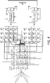
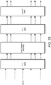
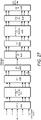
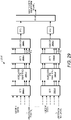
- FIG. 27 illustrates an example of a hybrid-s-OFDM based transmitter and receiver.
- a hybrid-s-OFDM transmitter and receiver system may reuse the OFDM transmitter and receiver design.
- a hybrid-s-OFDM transmitter may include one or more of the following: DFT-S module 2702, subcarrier mapping module 2704, IFFT module 2706, CP add module 2708.
- a hybrid-s-OFDM receiver may include one or more of the following: CP remove module 2710, FFT, 2712, subcarrier de-mapping module 2714, one tap equalizer 2716, and DFT-DS module 2718.
- a hybrid-s-OFDM transmitter may use DFT-S module 2702 to spread the transmitted signal or data including zeros and convert them to frequency domain, use subcarrier mapping module 2704 to map spread signal or data to subcarriers in frequency domain, use IFFT module 2706 to convert frequency-domain signal or data to time-domain signal or data and generate LPT, and use CP add module 2708 to add or attach LPCP to the resulting time-domain signal or data.
- DFT-S module 2702 to spread the transmitted signal or data including zeros and convert them to frequency domain
- subcarrier mapping module 2704 to map spread signal or data to subcarriers in frequency domain
- use IFFT module 2706 to convert frequency-domain signal or data to time-domain signal or data and generate LPT
- CP add module 2708 to add or attach LPCP to the resulting time-domain signal or data.
- a hybrid-s-OFDM receiver may use CP remove module 2710 to remove LPCP from the received time-domain signal or data, use FFT 2712 to convert time-domain signal or data to frequency domain signal or data, use subcarrier de-mapping module 2714 to de-map the subcarriers to obtain the corresponding signal or data in subcarriers, use one tap equalizer 2716 to equalize the corresponding signal or data, and use DFT-DS module 2718 to de-spread the signal or data and convert the frequency-domain signal or data to time-domain signal or data.
- CP remove module 2710 to remove LPCP from the received time-domain signal or data
- FFT 2712 to convert time-domain signal or data to frequency domain signal or data
- subcarrier de-mapping module 2714 to de-map the subcarriers to obtain the corresponding signal or data in subcarriers
- use one tap equalizer 2716 to equalize the corresponding signal or data
- DFT-DS module 2718 to de-spread the signal or data
- Hybrid-s-OFDM may have a low complexity transmitter and receiver, e.g., with one-tap equalizer.
- additional zeros may be inserted on top of input of DFT-s 2802. For example, some zeros may be added to the first part of DFT-s input, followed by data which is again followed by some zeros.
- Multi-user multiplexing for hybrid-s-OFDM may be provided. As illustrated in FIG. 29 , a plurality of users may be multiplexed using hybrid-s-OFDM systems. The multi-user multiplexing may be used in both UL and DL.
- a hybrid-s-OFDM transmitter 2900 may use FFT (or DFT-S) modules 2902-1 to 2902-K to spread the transmitted signal or data including zeros for users 1 to K, and convert signal/data of users 1 to K to frequency domain.
- subcarrier mapping modules 2904-1 to 2904-K may be used to map spread signal or data of users 1 to K to subcarriers of corresponding IFFT modules 2906-1 to 2906-K in frequency domain.
- IFFT modules 2906-1 to 2906-K may be used to convert frequency-domain signal or data of users 1 to K to time-domain signal or data and generate LPT.
- CP add modules 2908-1 to 2908-K may be used to add or attach LPCP to the resulting time-domain signal or data of users 1 to K.
- FIG. 30 illustrates an example of multi-user multiplexing for Hybrid-s-OFDM.
- a hybrid-s-OFDM transmitter 3000 may use FFT (or DFT-S) modules 3002-1 to 3002-K to spread the transmitting signal or data including zeros associated with users 1 to K and convert signal/data of users 1 to K to frequency domain.
- the transmitter 3000 may use subcarrier mapping modules 3004-1 to 3004-K to map spread signal or data of users 1 to K to subcarriers in frequency domain.
- the transmitter 3000 may use an IFFT module 3006 to convert frequency-domain signal or data to time-domain signal or data and generate LPT.
- the transmitter 3000 may use a CP add module 3008 to add or attach LPCP to the resulting time-domain signal or data.
- CP and/or hybrid-s-OFDM waveforms may have similar and/or comparable performances.
- Systems based on CP and/or hybrid-s-OFDM waveforms may outperform the systems based on ZT waveform.
- a symbol m in a subframe n may be denoted as S n m and the ZT length of symbol m in subframe n may be l S n m
- the total number of symbols in a subframe may be M.
- K consecutive symbols in a subframe may be indexed by S n 1 : k .
- ISI Inter-symbol interference
- the symbol l S n 1 may suffer from ISI.
- the symbol l S n m may suffer from ISI.
- This may include scenarios where the symbol n has cyclic prefix (e.g., only cyclic prefix), e.g., ZT length of zero, followed by a symbol n+1 with non-zero ZT length.
- the symbol at the switching boundary may experience ISI. This may be due to the symbols in ZT waveform not being self-contained and/or depend on the tail in previous symbol to account for channel delay spread.
- Addressing ISI at switching point between short ZT to long ZT may include a predefined ZT length, e.g., at the end of allocation and/or subframe.
- the last symbol of an allocation and/or a subframe may use a zero tail (e.g., a zero tail that is equal to a predefined ZT length), for example, equal to common channel ZT length.
- WTRUs may assume a common channel ZT length at the end of allocation and/or subframe, independent of the WTRU specific ZT length signaled and/or used for other symbols in the allocation or subframe.
- Hybrid solutions may be possible, e.g., where the subframe boundaries use predefined ZT length, whereas the WTRU specific allocations within the subframe may use extended ZT length. Additional zeros for extended ZT and/or predefined ZT may be generated as disclosed herein.
- LPT low power tail
- HGI may vary from symbol to symbol, transmission time interval (TTI) to TTI (e.g., for the same user), and may take different LTP and/or HGI lengths, e.g., for different users simultaneously.
- the length of the LPT and/or HGI may be set, e.g., by changing the number of zeros fed at the tail of the DFT for hybrid-s-OFDM.
- the head may be fed with non-zero number of zeros, e.g., to further reduce tail power and/or out-of-band (OOB) emissions.
- OOB out-of-band
- the non-zero number of zeros to create zero head may be in addition to the number of the zeros fed to obtain required tail length.
- the length of low power tail (LPT) and/or hybrid guard interval (HGI) may be driven by one or more following factors: the amount of delay spread to be addressed in a given TTI(s) (e.g., the amount of delay spread to be addressed in a given TTI(s) for a specific user, user group and/or beam, etc.), the length of the prefix and/or suffix or other purpose where the LPT and HGI may be used.
- a prefix and/or a suffix factor may be considered, for example, if a prefix or suffix such as pilot and/or unique word (UW) is utilized for different purposes, for example for synchronization, channel estimation, phase/gain tracking, identification of a specific user or a group of users based on prefix or suffix sequence or combination of both.
- a prefix or suffix such as pilot and/or unique word (UW)
- UW unique word
- the length of LPT (and/or HGI) may be set differently for different physical layer control channels. This may be driven by a variety of factors. For example, the beam-width with which the physical layer control channels (e.g., each of the physical layer control channels) may be transmitted may be different and/or may require lengths of LPT (and/or HGI) (e.g., different lengths of LPT (and/or HGI)) to compensate to handle the required delay spreads.
- the physical layer control channels may be transmitted with a beam-width, e.g., a wider beam-width compared to the physical layer data channels.
- the physical layer common control channel may be transmitted with a wider beam-width compared to physical layer dedicated control channel, e.g., even within the physical layer control channels.
- This may imply that the length of the LPT and/or HGI, to be utilized, may vary from physical layer control channels to physical layer data channels and/or within physical layer control and/or data channels, the LPT or HGI lengths may be different.
- the scenarios may not be restricted where the beam-width and/or the LPT or HGI length could be same (e.g., the same between physical layer control and/or physical layer data and/or physical layer common vs. physical layer dedicated channels).
Landscapes
- Engineering & Computer Science (AREA)
- Computer Networks & Wireless Communication (AREA)
- Signal Processing (AREA)
- Physics & Mathematics (AREA)
- Discrete Mathematics (AREA)
- General Physics & Mathematics (AREA)
- Mathematical Physics (AREA)
- Mobile Radio Communication Systems (AREA)
Claims (11)
- Verfahren zum Erzeugen einer Wellenform hybrider Aufspreizung, wobei das Verfahren Folgendes umfasst:Erzeugen der Wellenform hybrider Aufspreizung, die einen Datenabschnitt und einen HGI(Hybrid Guard Interval)-Abschnitt umfasst, wobei der HGI-Abschnitt einen unveränderlichen Abschnitt und einen adaptiven LPT(Low Power Tail)-Abschnitt umfasst, wobei der unveränderliche Abschnitt ein unveränderlicher Präfix-Abschnitt oder ein unveränderlicher Suffix-Abschnitt ist und der unveränderliche Abschnitt einen unveränderlichen LPCP(Low Power Cyclic Prefix)-Abschnitt umfasst, und wobei der adaptive LPT-Abschnitt dynamisch basierend auf einer Kanalverzögerungsspreizung und einer LPCP-Länge angepasst wird, und wobei die LPCP-Länge basierend auf Verzögerungsspreizung und Leistungswiederherstellungslänge berechnet wird; undÜbertragen der erzeugten Wellenform hybrider Aufspreizung, die den Datenabschnitt und den HGI-Abschnitt umfasst.
- Verfahren nach Anspruch 1, wobei der adaptive LPT-Abschnitt unter Verwendung eines ZT (Zero Tail) erzeugt wird, wobei der adaptive LPT-Abschnitt durch Einfügen von Nullen in einer IFFT(Inverse Fast Fourier Transform)- oder DFT(Discrete Fourier Transform)-Verarbeitungsstufe erzeugt wird.
- Verfahren nach Anspruch 1, ferner umfassend Empfangen eines oder mehrerer von einer HGI(Hybrid Guard Interval)-Länge, einer adaptiven LPT(Low Power Tail)-Länge oder einer Angabe einer Anzahl von Nullen, die vor einer FFT(Fast Fourier Transform)- oder DFT(Discrete Fourier Transform)-Verarbeitungsstufe eingefügt werden sollen, wobei eines oder mehrere von der HGI-Länge, der adaptiven LPT-Länge oder der Angabe der Anzahl von Nullen über einen Physical Control Channel, über MAC(Medium Access Control)-Signalübertragung oder über RRC(Radio Resource Control)-Signalübertragung empfangen werden.
- Verfahren nach Anspruch 1, wobei ein Teil des adaptiven LPT-Abschnitts zum Transportieren von Daten oder Steuerinformationen verwendet wird.
- Verfahren nach Anspruch 1, ferner umfassend Empfangen einer Steuersignalübertragung, die ein Umschalten des Wellenformtyps zwischen einer Wellenform mit unveränderlichem CP und der Wellenform hybrider Aufspreizung anzeigt.
- Drahtlose Sende-/Empfangseinheit (WTRU - Wireless Transmit/Receive Unit), umfassend:
einen Prozessor, der zumindest dafür konfiguriert ist:eine Wellenform hybrider Aufspreizung zu erzeugen, die einen Datenabschnitt und einen HGI(Hybrid Guard Interval)-Abschnitt umfasst, wobei der HGI-Abschnitt einen unveränderlichen Abschnitt und einen adaptiven LPT(Low Power Tail)-Abschnitt umfasst, wobei der unveränderliche Abschnitt ein unveränderlicher Präfix-Abschnitt oder ein unveränderlicher Suffix-Abschnitt ist, und der unveränderliche Abschnitt einen unveränderlichen LPCP(Low Power Cyclic Prefix)-Abschnitt umfasst, und wobei der adaptive LPT-Abschnitt dynamisch basierend auf einer Kanalverzögerungsspreizung und einer LPCP-Länge angepasst wird, und wobei die LPCP-Länge basierend auf Verzögerungsspreizung und Leistungswiederherstellungslänge berechnet wird; undeinen Sender, der zumindest dafür konfiguriert ist, die Wellenform hybrider Aufspreizung, die den Datenabschnitt und den HGI-Abschnitt umfasst, zu übertragen. - WTRU nach Anspruch 6, wobei der adaptive LPT-Abschnitt unter Verwendung eines ZT (Zero Tail) erzeugt wird, wobei der adaptive LPT-Abschnitt durch Einfügen von Nullen vor einer FFT(Inverse Fast Fourier Transform)- oder DFT(Discrete Fourier Transform)-Verarbeitungsstufe erzeugt wird.
- WTRU nach Anspruch 6, die einen Empfänger umfasst, der konfiguriert ist, zumindest eine oder mehrere von einer HGI(Hybrid Guard Interval)-Länge, einer adaptiven LPT(Low Power Tail)-Länge oder einer Angabe einer Anzahl von Nullen, die vor einer FFT- oder DFT-Verarbeitungsstufe eingefügt werden, zu empfangen.
- WTRU nach Anspruch 8, wobei eine oder mehrere von der HGI(Hybrid Guard Interval)-Länge, der adaptiven LPT(Low Power Tail)-Länge oder der Angabe der Anzahl von Nullen über einen Physical Control Channel, über MAC(Medium Access Control)- oder über RRC(Radio Resource Control)-Signalübertragung empfangen werden.
- WTRU nach Anspruch 6, wobei ein Teil des adaptiven LPT-Abschnitts zum Transportieren von Daten oder Steuerinformationen verwendet wird.
- WTRU nach Anspruch 6, die einen Empfänger umfasst, der konfiguriert ist, zumindest eine Steuersignalübertragung zu empfangen, die ein Umschalten des Wellenformtyps zwischen einer Wellenform mit unveränderlichem CP und der Wellenform hybrider Aufspreizung anzeigt.
Applications Claiming Priority (2)
| Application Number | Priority Date | Filing Date | Title |
|---|---|---|---|
| US201562262655P | 2015-12-03 | 2015-12-03 | |
| PCT/US2016/064564 WO2017096131A1 (en) | 2015-12-03 | 2016-12-02 | Use of both cyclic prefix and zero tail in dft-spread-ofdm |
Publications (2)
| Publication Number | Publication Date |
|---|---|
| EP3384649A1 EP3384649A1 (de) | 2018-10-10 |
| EP3384649B1 true EP3384649B1 (de) | 2022-09-28 |
Family
ID=57570616
Family Applications (1)
| Application Number | Title | Priority Date | Filing Date |
|---|---|---|---|
| EP16813289.2A Active EP3384649B1 (de) | 2015-12-03 | 2016-12-02 | Verwendung von sowohl zyklischem präfix als auch zero-tail in dft-spread-ofdm |
Country Status (6)
| Country | Link |
|---|---|
| US (1) | US10536312B2 (de) |
| EP (1) | EP3384649B1 (de) |
| JP (1) | JP6746698B2 (de) |
| KR (1) | KR102168571B1 (de) |
| CN (1) | CN108370359B (de) |
| WO (1) | WO2017096131A1 (de) |
Families Citing this family (31)
| Publication number | Priority date | Publication date | Assignee | Title |
|---|---|---|---|---|
| US10536946B2 (en) * | 2015-12-08 | 2020-01-14 | Huawei Technologies Co., Ltd. | Method and system for performing network slicing in a radio access network |
| US10772101B2 (en) | 2015-12-08 | 2020-09-08 | Huawei Technologies Co., Ltd. | Systems and methods for determining air interface configuration |
| EP3435566B1 (de) * | 2016-03-23 | 2020-12-02 | LG Electronics Inc. | Verfahren und vorrichtung zur übertragung eines entdeckungssignals |
| US10985958B2 (en) * | 2016-09-28 | 2021-04-20 | Idac Holdings, Inc. | Reference signal-free transmission for wireless systems |
| US11140715B2 (en) | 2016-10-26 | 2021-10-05 | Qualcomm Incorporated | Waveform-dependent random access channel procedure |
| KR102505734B1 (ko) * | 2017-01-13 | 2023-03-03 | 모토로라 모빌리티 엘엘씨 | 캐리어 주파수에서 경합 기반 랜덤 액세스를 수행하기 위한 방법 및 장치 |
| US10917278B2 (en) * | 2017-04-28 | 2021-02-09 | Nokia Technologies Oy | Frequency-domain transmitters and receivers which adapt to different subcarrier spacing configurations |
| US10700910B2 (en) | 2017-06-16 | 2020-06-30 | Qualcomm Incorporated | Single carrier waveform data transmission and reception based on configurable DFT window |
| US11109236B2 (en) * | 2017-11-09 | 2021-08-31 | Qualcomm Incorporated | Techniques for carrier feedback in wireless systems |
| US10944604B2 (en) * | 2018-05-25 | 2021-03-09 | Qualcomm Incorporated | System and method for communication sub-channel bandwidth adjustment in a millimeter wave (MMW) communication system |
| CN110830150B (zh) * | 2018-08-07 | 2023-06-09 | 黎光洁 | 一种用于无线通信的共享数据信道传输方法和设备 |
| US11223505B2 (en) * | 2018-08-22 | 2022-01-11 | Qualcomm Incorporated | Waveform multiplexing in millimeter wave band |
| US10638475B2 (en) | 2018-09-12 | 2020-04-28 | Verizon Patent And Licensing Inc. | Systems and methods for dynamically adjusting subframes |
| CN113302867B (zh) * | 2019-01-11 | 2023-08-08 | 上海诺基亚贝尔股份有限公司 | 用于多种参数集的公共信号结构 |
| CN111435905B (zh) | 2019-03-27 | 2021-06-18 | 维沃移动通信有限公司 | 一种信息发送方法及终端 |
| CN112217753B (zh) | 2019-07-12 | 2022-10-04 | 成都华为技术有限公司 | 符号处理的方法与装置 |
| WO2021156661A1 (en) | 2020-02-05 | 2021-08-12 | Zeku Inc. | Smooth orthogonal frequency division multiplexing symbols generation with varying gains |
| US11617171B2 (en) | 2020-12-28 | 2023-03-28 | Qualcomm Incorporated | Time gap with tail samples for high frequency bands |
| CN112910524A (zh) * | 2021-02-03 | 2021-06-04 | 电子科技大学 | 基于概率模型的毫米波波束跟踪方法 |
| US12063093B2 (en) * | 2021-06-10 | 2024-08-13 | Qualcomm Incorporated | Configurations for utilization of a padding duration |
| US11611459B1 (en) * | 2021-08-25 | 2023-03-21 | Qualcomm Incorporated | Symbol configuration for single-carrier for frequency domain equalization waveform |
| CN113824477B (zh) * | 2021-10-09 | 2023-04-28 | 北京邮电大学 | 离散透镜天线阵列辅助的多用户大规模mimo优化方法 |
| US11916712B2 (en) * | 2021-10-20 | 2024-02-27 | Qualcomm Incorporated | FDM UES with different guard intervals |
| US11870715B2 (en) * | 2022-02-07 | 2024-01-09 | Qualcomm Incorporated | Dynamic hybrid UW and CP based symbol formats |
| US20250286672A1 (en) * | 2022-05-02 | 2025-09-11 | Telefonaktiebolaget Lm Ericsson (Publ) | Single-carrier packet for reception by ofdm receiver |
| US12395214B2 (en) * | 2022-08-03 | 2025-08-19 | Qualcomm Incorporated | Switching to an adaptive beam weight-based hybrid beamforming procedure |
| CN119769072A (zh) * | 2022-08-26 | 2025-04-04 | 华为技术有限公司 | 用于传送零填充后的信号的方法、系统和装置 |
| WO2024065540A1 (zh) * | 2022-09-29 | 2024-04-04 | 华为技术有限公司 | 通信方法及装置 |
| US12375237B2 (en) * | 2022-10-14 | 2025-07-29 | Qualcomm Incorporated | Reference signal design for zero-tail orthogonal frequency division multiplexing communications |
| CN118784420A (zh) * | 2023-04-07 | 2024-10-15 | 华为技术有限公司 | 通信方法及相关装置 |
| CN119966782A (zh) * | 2023-11-07 | 2025-05-09 | 华为技术有限公司 | 一种配置方法及通信装置 |
Family Cites Families (15)
| Publication number | Priority date | Publication date | Assignee | Title |
|---|---|---|---|---|
| US7756002B2 (en) | 2003-01-30 | 2010-07-13 | Texas Instruments Incorporated | Time-frequency interleaved orthogonal frequency division multiplexing ultra wide band physical layer |
| CN101044704B (zh) * | 2004-08-13 | 2010-09-22 | 新加坡科技研究局 | 发射器、用于生成多个长前导的方法以及通信装置 |
| US8200233B2 (en) | 2007-09-21 | 2012-06-12 | Samsung Electronics Co., Ltd. | Apparatus and method for supporting cells with different characteristics in a broadband wireless communication system |
| KR101699493B1 (ko) * | 2010-05-03 | 2017-01-26 | 주식회사 팬택 | Mimo 환경에서 직교성을 제공하는 사이클릭 쉬프트 파라메터를 송수신하는 방법 및 장치 |
| CN101848036B (zh) | 2010-05-14 | 2013-08-21 | 北京邮电大学 | 光ofdm系统中基于si的光纤非线性损伤补偿方法及装置 |
| CN104025529B (zh) * | 2011-08-12 | 2018-02-09 | 交互数字专利控股公司 | 用于扩展载波与载波分段的参考信号配置 |
| CN103139125B (zh) * | 2011-12-02 | 2016-04-13 | 华为技术有限公司 | 下行数据发送、接收方法及基站与用户终端 |
| US8873655B2 (en) | 2013-01-10 | 2014-10-28 | Intel Corporation | Sending information at a band edge within an orthogonal frequency-division multiplexing (OFDM) symbol |
| WO2014124661A1 (en) * | 2013-02-12 | 2014-08-21 | Nokia Solutions And Networks Oy | Zero insertion for isi free ofdm reception |
| JP6789211B2 (ja) | 2014-09-08 | 2020-11-25 | インターデイジタル パテント ホールディングス インコーポレイテッド | 異なる送信時間間隔(tti)持続時間により動作するシステムおよび方法 |
| CN104683280B (zh) * | 2014-12-02 | 2018-04-24 | 北京星河亮点技术股份有限公司 | DFT-s-OFDM系统大频偏的精确估计方法 |
| WO2016105570A1 (en) | 2014-12-23 | 2016-06-30 | Interdigital Patent Holdings, Inc. | Latency reduction in lte systems |
| CN107113155B (zh) | 2015-01-15 | 2020-06-26 | 苹果公司 | 提供用于块单载波传输的灵活的保护间隔的装置和方法 |
| US9313063B1 (en) * | 2015-01-30 | 2016-04-12 | Huawei Technologies Co., Ltd. | Apparatus and method for transmitting data with conditional zero padding |
| US10154486B2 (en) * | 2015-10-30 | 2018-12-11 | Intel Corporation | Downlink signaling for UE specific cyclic prefix transmission |
-
2016
- 2016-12-02 EP EP16813289.2A patent/EP3384649B1/de active Active
- 2016-12-02 KR KR1020187017026A patent/KR102168571B1/ko active Active
- 2016-12-02 US US15/780,326 patent/US10536312B2/en active Active
- 2016-12-02 CN CN201680070856.3A patent/CN108370359B/zh active Active
- 2016-12-02 WO PCT/US2016/064564 patent/WO2017096131A1/en not_active Ceased
- 2016-12-02 JP JP2018527087A patent/JP6746698B2/ja active Active
Also Published As
| Publication number | Publication date |
|---|---|
| CN108370359A (zh) | 2018-08-03 |
| WO2017096131A1 (en) | 2017-06-08 |
| US10536312B2 (en) | 2020-01-14 |
| JP2019503607A (ja) | 2019-02-07 |
| KR20180100046A (ko) | 2018-09-06 |
| CN108370359B (zh) | 2021-06-04 |
| JP6746698B2 (ja) | 2020-08-26 |
| US20180367355A1 (en) | 2018-12-20 |
| KR102168571B1 (ko) | 2020-10-22 |
| EP3384649A1 (de) | 2018-10-10 |
Similar Documents
| Publication | Publication Date | Title |
|---|---|---|
| EP3384649B1 (de) | Verwendung von sowohl zyklischem präfix als auch zero-tail in dft-spread-ofdm | |
| US10608858B2 (en) | Zero tail and unique word based waveforms for DFT-s OFDM and OFDM | |
| US12495428B2 (en) | Downlink control channel design and signaling for beamformed systems | |
| US12150107B2 (en) | mmW physical layer downlink channel scheduling and control signaling | |
| US20240429995A1 (en) | Transmission schemes and modes and fallback schemes for the access link of systems operating in higher frequency bands |
Legal Events
| Date | Code | Title | Description |
|---|---|---|---|
| STAA | Information on the status of an ep patent application or granted ep patent |
Free format text: STATUS: UNKNOWN |
|
| STAA | Information on the status of an ep patent application or granted ep patent |
Free format text: STATUS: THE INTERNATIONAL PUBLICATION HAS BEEN MADE |
|
| PUAI | Public reference made under article 153(3) epc to a published international application that has entered the european phase |
Free format text: ORIGINAL CODE: 0009012 |
|
| STAA | Information on the status of an ep patent application or granted ep patent |
Free format text: STATUS: REQUEST FOR EXAMINATION WAS MADE |
|
| 17P | Request for examination filed |
Effective date: 20180628 |
|
| AK | Designated contracting states |
Kind code of ref document: A1 Designated state(s): AL AT BE BG CH CY CZ DE DK EE ES FI FR GB GR HR HU IE IS IT LI LT LU LV MC MK MT NL NO PL PT RO RS SE SI SK SM TR |
|
| AX | Request for extension of the european patent |
Extension state: BA ME |
|
| DAV | Request for validation of the european patent (deleted) | ||
| DAX | Request for extension of the european patent (deleted) | ||
| STAA | Information on the status of an ep patent application or granted ep patent |
Free format text: STATUS: EXAMINATION IS IN PROGRESS |
|
| 17Q | First examination report despatched |
Effective date: 20191216 |
|
| GRAP | Despatch of communication of intention to grant a patent |
Free format text: ORIGINAL CODE: EPIDOSNIGR1 |
|
| STAA | Information on the status of an ep patent application or granted ep patent |
Free format text: STATUS: GRANT OF PATENT IS INTENDED |
|
| INTG | Intention to grant announced |
Effective date: 20220419 |
|
| GRAS | Grant fee paid |
Free format text: ORIGINAL CODE: EPIDOSNIGR3 |
|
| GRAA | (expected) grant |
Free format text: ORIGINAL CODE: 0009210 |
|
| STAA | Information on the status of an ep patent application or granted ep patent |
Free format text: STATUS: THE PATENT HAS BEEN GRANTED |
|
| AK | Designated contracting states |
Kind code of ref document: B1 Designated state(s): AL AT BE BG CH CY CZ DE DK EE ES FI FR GB GR HR HU IE IS IT LI LT LU LV MC MK MT NL NO PL PT RO RS SE SI SK SM TR |
|
| REG | Reference to a national code |
Ref country code: GB Ref legal event code: FG4D |
|
| REG | Reference to a national code |
Ref country code: CH Ref legal event code: EP |
|
| REG | Reference to a national code |
Ref country code: DE Ref legal event code: R096 Ref document number: 602016075307 Country of ref document: DE |
|
| REG | Reference to a national code |
Ref country code: AT Ref legal event code: REF Ref document number: 1521998 Country of ref document: AT Kind code of ref document: T Effective date: 20221015 |
|
| REG | Reference to a national code |
Ref country code: IE Ref legal event code: FG4D |
|
| REG | Reference to a national code |
Ref country code: LT Ref legal event code: MG9D |
|
| REG | Reference to a national code |
Ref country code: NL Ref legal event code: FP |
|
| PG25 | Lapsed in a contracting state [announced via postgrant information from national office to epo] |
Ref country code: SE Free format text: LAPSE BECAUSE OF FAILURE TO SUBMIT A TRANSLATION OF THE DESCRIPTION OR TO PAY THE FEE WITHIN THE PRESCRIBED TIME-LIMIT Effective date: 20220928 Ref country code: RS Free format text: LAPSE BECAUSE OF FAILURE TO SUBMIT A TRANSLATION OF THE DESCRIPTION OR TO PAY THE FEE WITHIN THE PRESCRIBED TIME-LIMIT Effective date: 20220928 Ref country code: NO Free format text: LAPSE BECAUSE OF FAILURE TO SUBMIT A TRANSLATION OF THE DESCRIPTION OR TO PAY THE FEE WITHIN THE PRESCRIBED TIME-LIMIT Effective date: 20221228 Ref country code: LV Free format text: LAPSE BECAUSE OF FAILURE TO SUBMIT A TRANSLATION OF THE DESCRIPTION OR TO PAY THE FEE WITHIN THE PRESCRIBED TIME-LIMIT Effective date: 20220928 Ref country code: LT Free format text: LAPSE BECAUSE OF FAILURE TO SUBMIT A TRANSLATION OF THE DESCRIPTION OR TO PAY THE FEE WITHIN THE PRESCRIBED TIME-LIMIT Effective date: 20220928 Ref country code: FI Free format text: LAPSE BECAUSE OF FAILURE TO SUBMIT A TRANSLATION OF THE DESCRIPTION OR TO PAY THE FEE WITHIN THE PRESCRIBED TIME-LIMIT Effective date: 20220928 |
|
| REG | Reference to a national code |
Ref country code: AT Ref legal event code: MK05 Ref document number: 1521998 Country of ref document: AT Kind code of ref document: T Effective date: 20220928 |
|
| PG25 | Lapsed in a contracting state [announced via postgrant information from national office to epo] |
Ref country code: HR Free format text: LAPSE BECAUSE OF FAILURE TO SUBMIT A TRANSLATION OF THE DESCRIPTION OR TO PAY THE FEE WITHIN THE PRESCRIBED TIME-LIMIT Effective date: 20220928 Ref country code: GR Free format text: LAPSE BECAUSE OF FAILURE TO SUBMIT A TRANSLATION OF THE DESCRIPTION OR TO PAY THE FEE WITHIN THE PRESCRIBED TIME-LIMIT Effective date: 20221229 |
|
| RAP2 | Party data changed (patent owner data changed or rights of a patent transferred) |
Owner name: INTERDIGITAL PATENT HOLDINGS, INC. |
|
| PG25 | Lapsed in a contracting state [announced via postgrant information from national office to epo] |
Ref country code: SM Free format text: LAPSE BECAUSE OF FAILURE TO SUBMIT A TRANSLATION OF THE DESCRIPTION OR TO PAY THE FEE WITHIN THE PRESCRIBED TIME-LIMIT Effective date: 20220928 Ref country code: RO Free format text: LAPSE BECAUSE OF FAILURE TO SUBMIT A TRANSLATION OF THE DESCRIPTION OR TO PAY THE FEE WITHIN THE PRESCRIBED TIME-LIMIT Effective date: 20220928 Ref country code: PT Free format text: LAPSE BECAUSE OF FAILURE TO SUBMIT A TRANSLATION OF THE DESCRIPTION OR TO PAY THE FEE WITHIN THE PRESCRIBED TIME-LIMIT Effective date: 20230130 Ref country code: ES Free format text: LAPSE BECAUSE OF FAILURE TO SUBMIT A TRANSLATION OF THE DESCRIPTION OR TO PAY THE FEE WITHIN THE PRESCRIBED TIME-LIMIT Effective date: 20220928 Ref country code: CZ Free format text: LAPSE BECAUSE OF FAILURE TO SUBMIT A TRANSLATION OF THE DESCRIPTION OR TO PAY THE FEE WITHIN THE PRESCRIBED TIME-LIMIT Effective date: 20220928 Ref country code: AT Free format text: LAPSE BECAUSE OF FAILURE TO SUBMIT A TRANSLATION OF THE DESCRIPTION OR TO PAY THE FEE WITHIN THE PRESCRIBED TIME-LIMIT Effective date: 20220928 |
|
| PG25 | Lapsed in a contracting state [announced via postgrant information from national office to epo] |
Ref country code: SK Free format text: LAPSE BECAUSE OF FAILURE TO SUBMIT A TRANSLATION OF THE DESCRIPTION OR TO PAY THE FEE WITHIN THE PRESCRIBED TIME-LIMIT Effective date: 20220928 Ref country code: PL Free format text: LAPSE BECAUSE OF FAILURE TO SUBMIT A TRANSLATION OF THE DESCRIPTION OR TO PAY THE FEE WITHIN THE PRESCRIBED TIME-LIMIT Effective date: 20220928 Ref country code: IS Free format text: LAPSE BECAUSE OF FAILURE TO SUBMIT A TRANSLATION OF THE DESCRIPTION OR TO PAY THE FEE WITHIN THE PRESCRIBED TIME-LIMIT Effective date: 20230128 Ref country code: EE Free format text: LAPSE BECAUSE OF FAILURE TO SUBMIT A TRANSLATION OF THE DESCRIPTION OR TO PAY THE FEE WITHIN THE PRESCRIBED TIME-LIMIT Effective date: 20220928 |
|
| P01 | Opt-out of the competence of the unified patent court (upc) registered |
Effective date: 20230512 |
|
| REG | Reference to a national code |
Ref country code: DE Ref legal event code: R097 Ref document number: 602016075307 Country of ref document: DE |
|
| PG25 | Lapsed in a contracting state [announced via postgrant information from national office to epo] |
Ref country code: AL Free format text: LAPSE BECAUSE OF FAILURE TO SUBMIT A TRANSLATION OF THE DESCRIPTION OR TO PAY THE FEE WITHIN THE PRESCRIBED TIME-LIMIT Effective date: 20220928 |
|
| PG25 | Lapsed in a contracting state [announced via postgrant information from national office to epo] |
Ref country code: DK Free format text: LAPSE BECAUSE OF FAILURE TO SUBMIT A TRANSLATION OF THE DESCRIPTION OR TO PAY THE FEE WITHIN THE PRESCRIBED TIME-LIMIT Effective date: 20220928 |
|
| REG | Reference to a national code |
Ref country code: CH Ref legal event code: PL |
|
| PLBE | No opposition filed within time limit |
Free format text: ORIGINAL CODE: 0009261 |
|
| STAA | Information on the status of an ep patent application or granted ep patent |
Free format text: STATUS: NO OPPOSITION FILED WITHIN TIME LIMIT |
|
| REG | Reference to a national code |
Ref country code: BE Ref legal event code: MM Effective date: 20221231 |
|
| PG25 | Lapsed in a contracting state [announced via postgrant information from national office to epo] |
Ref country code: LU Free format text: LAPSE BECAUSE OF NON-PAYMENT OF DUE FEES Effective date: 20221202 |
|
| 26N | No opposition filed |
Effective date: 20230629 |
|
| PG25 | Lapsed in a contracting state [announced via postgrant information from national office to epo] |
Ref country code: LI Free format text: LAPSE BECAUSE OF NON-PAYMENT OF DUE FEES Effective date: 20221231 Ref country code: IE Free format text: LAPSE BECAUSE OF NON-PAYMENT OF DUE FEES Effective date: 20221202 Ref country code: CH Free format text: LAPSE BECAUSE OF NON-PAYMENT OF DUE FEES Effective date: 20221231 |
|
| PG25 | Lapsed in a contracting state [announced via postgrant information from national office to epo] |
Ref country code: SI Free format text: LAPSE BECAUSE OF FAILURE TO SUBMIT A TRANSLATION OF THE DESCRIPTION OR TO PAY THE FEE WITHIN THE PRESCRIBED TIME-LIMIT Effective date: 20220928 Ref country code: BE Free format text: LAPSE BECAUSE OF NON-PAYMENT OF DUE FEES Effective date: 20221231 |
|
| PG25 | Lapsed in a contracting state [announced via postgrant information from national office to epo] |
Ref country code: HU Free format text: LAPSE BECAUSE OF FAILURE TO SUBMIT A TRANSLATION OF THE DESCRIPTION OR TO PAY THE FEE WITHIN THE PRESCRIBED TIME-LIMIT; INVALID AB INITIO Effective date: 20161202 |
|
| PG25 | Lapsed in a contracting state [announced via postgrant information from national office to epo] |
Ref country code: CY Free format text: LAPSE BECAUSE OF FAILURE TO SUBMIT A TRANSLATION OF THE DESCRIPTION OR TO PAY THE FEE WITHIN THE PRESCRIBED TIME-LIMIT Effective date: 20220928 |
|
| REG | Reference to a national code |
Ref country code: DE Ref legal event code: R081 Ref document number: 602016075307 Country of ref document: DE Owner name: INTERDIGITAL PATENT HOLDINGS, INC., WILMINGTON, US Free format text: FORMER OWNER: IDAC HOLDINGS, INC., WILMINGTON, DE, US |
|
| REG | Reference to a national code |
Ref country code: GB Ref legal event code: 732E Free format text: REGISTERED BETWEEN 20240425 AND 20240501 |
|
| PG25 | Lapsed in a contracting state [announced via postgrant information from national office to epo] |
Ref country code: MK Free format text: LAPSE BECAUSE OF FAILURE TO SUBMIT A TRANSLATION OF THE DESCRIPTION OR TO PAY THE FEE WITHIN THE PRESCRIBED TIME-LIMIT Effective date: 20220928 Ref country code: IT Free format text: LAPSE BECAUSE OF FAILURE TO SUBMIT A TRANSLATION OF THE DESCRIPTION OR TO PAY THE FEE WITHIN THE PRESCRIBED TIME-LIMIT Effective date: 20220928 |
|
| PG25 | Lapsed in a contracting state [announced via postgrant information from national office to epo] |
Ref country code: MC Free format text: LAPSE BECAUSE OF FAILURE TO SUBMIT A TRANSLATION OF THE DESCRIPTION OR TO PAY THE FEE WITHIN THE PRESCRIBED TIME-LIMIT Effective date: 20220928 |
|
| PG25 | Lapsed in a contracting state [announced via postgrant information from national office to epo] |
Ref country code: MC Free format text: LAPSE BECAUSE OF FAILURE TO SUBMIT A TRANSLATION OF THE DESCRIPTION OR TO PAY THE FEE WITHIN THE PRESCRIBED TIME-LIMIT Effective date: 20220928 |
|
| PG25 | Lapsed in a contracting state [announced via postgrant information from national office to epo] |
Ref country code: BG Free format text: LAPSE BECAUSE OF FAILURE TO SUBMIT A TRANSLATION OF THE DESCRIPTION OR TO PAY THE FEE WITHIN THE PRESCRIBED TIME-LIMIT Effective date: 20220928 |
|
| PG25 | Lapsed in a contracting state [announced via postgrant information from national office to epo] |
Ref country code: MT Free format text: LAPSE BECAUSE OF FAILURE TO SUBMIT A TRANSLATION OF THE DESCRIPTION OR TO PAY THE FEE WITHIN THE PRESCRIBED TIME-LIMIT Effective date: 20220928 |
|
| REG | Reference to a national code |
Ref country code: NL Ref legal event code: PD Owner name: INTERDIGITAL PATENT HOLDINGS, INC.; US Free format text: DETAILS ASSIGNMENT: CHANGE OF OWNER(S), ASSIGNMENT; FORMER OWNER NAME: IDAC HOLDINGS, INC. Effective date: 20250303 |
|
| PGFP | Annual fee paid to national office [announced via postgrant information from national office to epo] |
Ref country code: DE Payment date: 20241227 Year of fee payment: 9 |
|
| PG25 | Lapsed in a contracting state [announced via postgrant information from national office to epo] |
Ref country code: TR Free format text: LAPSE BECAUSE OF FAILURE TO SUBMIT A TRANSLATION OF THE DESCRIPTION OR TO PAY THE FEE WITHIN THE PRESCRIBED TIME-LIMIT Effective date: 20220928 |
|
| PGFP | Annual fee paid to national office [announced via postgrant information from national office to epo] |
Ref country code: GB Payment date: 20251223 Year of fee payment: 10 |
|
| PGFP | Annual fee paid to national office [announced via postgrant information from national office to epo] |
Ref country code: NL Payment date: 20251222 Year of fee payment: 10 Ref country code: FR Payment date: 20251223 Year of fee payment: 10 |