EP3384368B1 - Folie sowie verfahren zur herstellung einer folie - Google Patents
Folie sowie verfahren zur herstellung einer folie Download PDFInfo
- Publication number
- EP3384368B1 EP3384368B1 EP16798736.1A EP16798736A EP3384368B1 EP 3384368 B1 EP3384368 B1 EP 3384368B1 EP 16798736 A EP16798736 A EP 16798736A EP 3384368 B1 EP3384368 B1 EP 3384368B1
- Authority
- EP
- European Patent Office
- Prior art keywords
- layer
- film
- electrically conductive
- adhesion
- carrier substrate
- Prior art date
- Legal status (The legal status is an assumption and is not a legal conclusion. Google has not performed a legal analysis and makes no representation as to the accuracy of the status listed.)
- Active
Links
Images








Classifications
-
- G—PHYSICS
- G06—COMPUTING OR CALCULATING; COUNTING
- G06F—ELECTRIC DIGITAL DATA PROCESSING
- G06F3/00—Input arrangements for transferring data to be processed into a form capable of being handled by the computer; Output arrangements for transferring data from processing unit to output unit, e.g. interface arrangements
- G06F3/01—Input arrangements or combined input and output arrangements for interaction between user and computer
- G06F3/03—Arrangements for converting the position or the displacement of a member into a coded form
- G06F3/041—Digitisers, e.g. for touch screens or touch pads, characterised by the transducing means
- G06F3/044—Digitisers, e.g. for touch screens or touch pads, characterised by the transducing means by capacitive means
-
- G—PHYSICS
- G06—COMPUTING OR CALCULATING; COUNTING
- G06F—ELECTRIC DIGITAL DATA PROCESSING
- G06F3/00—Input arrangements for transferring data to be processed into a form capable of being handled by the computer; Output arrangements for transferring data from processing unit to output unit, e.g. interface arrangements
- G06F3/01—Input arrangements or combined input and output arrangements for interaction between user and computer
- G06F3/03—Arrangements for converting the position or the displacement of a member into a coded form
- G06F3/041—Digitisers, e.g. for touch screens or touch pads, characterised by the transducing means
- G06F3/044—Digitisers, e.g. for touch screens or touch pads, characterised by the transducing means by capacitive means
- G06F3/0446—Digitisers, e.g. for touch screens or touch pads, characterised by the transducing means by capacitive means using a grid-like structure of electrodes in at least two directions, e.g. using row and column electrodes
-
- C—CHEMISTRY; METALLURGY
- C09—DYES; PAINTS; POLISHES; NATURAL RESINS; ADHESIVES; COMPOSITIONS NOT OTHERWISE PROVIDED FOR; APPLICATIONS OF MATERIALS NOT OTHERWISE PROVIDED FOR
- C09J—ADHESIVES; NON-MECHANICAL ASPECTS OF ADHESIVE PROCESSES IN GENERAL; ADHESIVE PROCESSES NOT PROVIDED FOR ELSEWHERE; USE OF MATERIALS AS ADHESIVES
- C09J7/00—Adhesives in the form of films or foils
- C09J7/20—Adhesives in the form of films or foils characterised by their carriers
- C09J7/29—Laminated material
-
- B—PERFORMING OPERATIONS; TRANSPORTING
- B32—LAYERED PRODUCTS
- B32B—LAYERED PRODUCTS, i.e. PRODUCTS BUILT-UP OF STRATA OF FLAT OR NON-FLAT, e.g. CELLULAR OR HONEYCOMB, FORM
- B32B37/00—Methods or apparatus for laminating, e.g. by curing or by ultrasonic bonding
- B32B37/06—Methods or apparatus for laminating, e.g. by curing or by ultrasonic bonding characterised by the heating method
-
- B—PERFORMING OPERATIONS; TRANSPORTING
- B32—LAYERED PRODUCTS
- B32B—LAYERED PRODUCTS, i.e. PRODUCTS BUILT-UP OF STRATA OF FLAT OR NON-FLAT, e.g. CELLULAR OR HONEYCOMB, FORM
- B32B37/00—Methods or apparatus for laminating, e.g. by curing or by ultrasonic bonding
- B32B37/12—Methods or apparatus for laminating, e.g. by curing or by ultrasonic bonding characterised by using adhesives
- B32B37/1284—Application of adhesive
- B32B37/1292—Application of adhesive selectively, e.g. in stripes, in patterns
-
- B—PERFORMING OPERATIONS; TRANSPORTING
- B32—LAYERED PRODUCTS
- B32B—LAYERED PRODUCTS, i.e. PRODUCTS BUILT-UP OF STRATA OF FLAT OR NON-FLAT, e.g. CELLULAR OR HONEYCOMB, FORM
- B32B7/00—Layered products characterised by the relation between layers; Layered products characterised by the relative orientation of features between layers, or by the relative values of a measurable parameter between layers, i.e. products comprising layers having different physical, chemical or physicochemical properties; Layered products characterised by the interconnection of layers
- B32B7/04—Interconnection of layers
- B32B7/12—Interconnection of layers using interposed adhesives or interposed materials with bonding properties
- B32B7/14—Interconnection of layers using interposed adhesives or interposed materials with bonding properties applied in spaced arrangements, e.g. in stripes
-
- C—CHEMISTRY; METALLURGY
- C09—DYES; PAINTS; POLISHES; NATURAL RESINS; ADHESIVES; COMPOSITIONS NOT OTHERWISE PROVIDED FOR; APPLICATIONS OF MATERIALS NOT OTHERWISE PROVIDED FOR
- C09D—COATING COMPOSITIONS, e.g. PAINTS, VARNISHES OR LACQUERS; FILLING PASTES; CHEMICAL PAINT OR INK REMOVERS; INKS; CORRECTING FLUIDS; WOODSTAINS; PASTES OR SOLIDS FOR COLOURING OR PRINTING; USE OF MATERIALS THEREFOR
- C09D127/00—Coating compositions based on homopolymers or copolymers of compounds having one or more unsaturated aliphatic radicals, each having only one carbon-to-carbon double bond, and at least one being terminated by a halogen; Coating compositions based on derivatives of such polymers
- C09D127/02—Coating compositions based on homopolymers or copolymers of compounds having one or more unsaturated aliphatic radicals, each having only one carbon-to-carbon double bond, and at least one being terminated by a halogen; Coating compositions based on derivatives of such polymers not modified by chemical after-treatment
- C09D127/04—Coating compositions based on homopolymers or copolymers of compounds having one or more unsaturated aliphatic radicals, each having only one carbon-to-carbon double bond, and at least one being terminated by a halogen; Coating compositions based on derivatives of such polymers not modified by chemical after-treatment containing chlorine atoms
- C09D127/06—Homopolymers or copolymers of vinyl chloride
-
- C—CHEMISTRY; METALLURGY
- C09—DYES; PAINTS; POLISHES; NATURAL RESINS; ADHESIVES; COMPOSITIONS NOT OTHERWISE PROVIDED FOR; APPLICATIONS OF MATERIALS NOT OTHERWISE PROVIDED FOR
- C09D—COATING COMPOSITIONS, e.g. PAINTS, VARNISHES OR LACQUERS; FILLING PASTES; CHEMICAL PAINT OR INK REMOVERS; INKS; CORRECTING FLUIDS; WOODSTAINS; PASTES OR SOLIDS FOR COLOURING OR PRINTING; USE OF MATERIALS THEREFOR
- C09D133/00—Coating compositions based on homopolymers or copolymers of compounds having one or more unsaturated aliphatic radicals, each having only one carbon-to-carbon double bond, and at least one being terminated by only one carboxyl radical, or of salts, anhydrides, esters, amides, imides, or nitriles thereof; Coating compositions based on derivatives of such polymers
- C09D133/04—Homopolymers or copolymers of esters
- C09D133/06—Homopolymers or copolymers of esters of esters containing only carbon, hydrogen and oxygen, the oxygen atom being present only as part of the carboxyl radical
- C09D133/10—Homopolymers or copolymers of methacrylic acid esters
- C09D133/12—Homopolymers or copolymers of methyl methacrylate
-
- C—CHEMISTRY; METALLURGY
- C09—DYES; PAINTS; POLISHES; NATURAL RESINS; ADHESIVES; COMPOSITIONS NOT OTHERWISE PROVIDED FOR; APPLICATIONS OF MATERIALS NOT OTHERWISE PROVIDED FOR
- C09D—COATING COMPOSITIONS, e.g. PAINTS, VARNISHES OR LACQUERS; FILLING PASTES; CHEMICAL PAINT OR INK REMOVERS; INKS; CORRECTING FLUIDS; WOODSTAINS; PASTES OR SOLIDS FOR COLOURING OR PRINTING; USE OF MATERIALS THEREFOR
- C09D175/00—Coating compositions based on polyureas or polyurethanes; Coating compositions based on derivatives of such polymers
- C09D175/04—Polyurethanes
-
- C—CHEMISTRY; METALLURGY
- C09—DYES; PAINTS; POLISHES; NATURAL RESINS; ADHESIVES; COMPOSITIONS NOT OTHERWISE PROVIDED FOR; APPLICATIONS OF MATERIALS NOT OTHERWISE PROVIDED FOR
- C09J—ADHESIVES; NON-MECHANICAL ASPECTS OF ADHESIVE PROCESSES IN GENERAL; ADHESIVE PROCESSES NOT PROVIDED FOR ELSEWHERE; USE OF MATERIALS AS ADHESIVES
- C09J127/00—Adhesives based on homopolymers or copolymers of compounds having one or more unsaturated aliphatic radicals, each having only one carbon-to-carbon double bond, and at least one being terminated by a halogen; Adhesives based on derivatives of such polymers
- C09J127/02—Adhesives based on homopolymers or copolymers of compounds having one or more unsaturated aliphatic radicals, each having only one carbon-to-carbon double bond, and at least one being terminated by a halogen; Adhesives based on derivatives of such polymers not modified by chemical after-treatment
- C09J127/04—Adhesives based on homopolymers or copolymers of compounds having one or more unsaturated aliphatic radicals, each having only one carbon-to-carbon double bond, and at least one being terminated by a halogen; Adhesives based on derivatives of such polymers not modified by chemical after-treatment containing chlorine atoms
- C09J127/06—Homopolymers or copolymers of vinyl chloride
-
- C—CHEMISTRY; METALLURGY
- C09—DYES; PAINTS; POLISHES; NATURAL RESINS; ADHESIVES; COMPOSITIONS NOT OTHERWISE PROVIDED FOR; APPLICATIONS OF MATERIALS NOT OTHERWISE PROVIDED FOR
- C09J—ADHESIVES; NON-MECHANICAL ASPECTS OF ADHESIVE PROCESSES IN GENERAL; ADHESIVE PROCESSES NOT PROVIDED FOR ELSEWHERE; USE OF MATERIALS AS ADHESIVES
- C09J133/00—Adhesives based on homopolymers or copolymers of compounds having one or more unsaturated aliphatic radicals, each having only one carbon-to-carbon double bond, and at least one being terminated by only one carboxyl radical, or of salts, anhydrides, esters, amides, imides, or nitriles thereof; Adhesives based on derivatives of such polymers
- C09J133/04—Homopolymers or copolymers of esters
- C09J133/06—Homopolymers or copolymers of esters of esters containing only carbon, hydrogen and oxygen, the oxygen atom being present only as part of the carboxyl radical
- C09J133/10—Homopolymers or copolymers of methacrylic acid esters
- C09J133/12—Homopolymers or copolymers of methyl methacrylate
-
- C—CHEMISTRY; METALLURGY
- C09—DYES; PAINTS; POLISHES; NATURAL RESINS; ADHESIVES; COMPOSITIONS NOT OTHERWISE PROVIDED FOR; APPLICATIONS OF MATERIALS NOT OTHERWISE PROVIDED FOR
- C09J—ADHESIVES; NON-MECHANICAL ASPECTS OF ADHESIVE PROCESSES IN GENERAL; ADHESIVE PROCESSES NOT PROVIDED FOR ELSEWHERE; USE OF MATERIALS AS ADHESIVES
- C09J175/00—Adhesives based on polyureas or polyurethanes; Adhesives based on derivatives of such polymers
- C09J175/04—Polyurethanes
-
- C—CHEMISTRY; METALLURGY
- C09—DYES; PAINTS; POLISHES; NATURAL RESINS; ADHESIVES; COMPOSITIONS NOT OTHERWISE PROVIDED FOR; APPLICATIONS OF MATERIALS NOT OTHERWISE PROVIDED FOR
- C09J—ADHESIVES; NON-MECHANICAL ASPECTS OF ADHESIVE PROCESSES IN GENERAL; ADHESIVE PROCESSES NOT PROVIDED FOR ELSEWHERE; USE OF MATERIALS AS ADHESIVES
- C09J7/00—Adhesives in the form of films or foils
-
- G—PHYSICS
- G06—COMPUTING OR CALCULATING; COUNTING
- G06F—ELECTRIC DIGITAL DATA PROCESSING
- G06F3/00—Input arrangements for transferring data to be processed into a form capable of being handled by the computer; Output arrangements for transferring data from processing unit to output unit, e.g. interface arrangements
- G06F3/01—Input arrangements or combined input and output arrangements for interaction between user and computer
- G06F3/03—Arrangements for converting the position or the displacement of a member into a coded form
- G06F3/041—Digitisers, e.g. for touch screens or touch pads, characterised by the transducing means
-
- B—PERFORMING OPERATIONS; TRANSPORTING
- B32—LAYERED PRODUCTS
- B32B—LAYERED PRODUCTS, i.e. PRODUCTS BUILT-UP OF STRATA OF FLAT OR NON-FLAT, e.g. CELLULAR OR HONEYCOMB, FORM
- B32B2255/00—Coating on the layer surface
- B32B2255/20—Inorganic coating
- B32B2255/205—Metallic coating
-
- B—PERFORMING OPERATIONS; TRANSPORTING
- B32—LAYERED PRODUCTS
- B32B—LAYERED PRODUCTS, i.e. PRODUCTS BUILT-UP OF STRATA OF FLAT OR NON-FLAT, e.g. CELLULAR OR HONEYCOMB, FORM
- B32B2307/00—Properties of the layers or laminate
- B32B2307/20—Properties of the layers or laminate having particular electrical or magnetic properties, e.g. piezoelectric
- B32B2307/202—Conductive
-
- B—PERFORMING OPERATIONS; TRANSPORTING
- B32—LAYERED PRODUCTS
- B32B—LAYERED PRODUCTS, i.e. PRODUCTS BUILT-UP OF STRATA OF FLAT OR NON-FLAT, e.g. CELLULAR OR HONEYCOMB, FORM
- B32B2309/00—Parameters for the laminating or treatment process; Apparatus details
- B32B2309/02—Temperature
-
- B—PERFORMING OPERATIONS; TRANSPORTING
- B32—LAYERED PRODUCTS
- B32B—LAYERED PRODUCTS, i.e. PRODUCTS BUILT-UP OF STRATA OF FLAT OR NON-FLAT, e.g. CELLULAR OR HONEYCOMB, FORM
- B32B2457/00—Electrical equipment
- B32B2457/20—Displays, e.g. liquid crystal displays, plasma displays
- B32B2457/208—Touch screens
-
- C—CHEMISTRY; METALLURGY
- C09—DYES; PAINTS; POLISHES; NATURAL RESINS; ADHESIVES; COMPOSITIONS NOT OTHERWISE PROVIDED FOR; APPLICATIONS OF MATERIALS NOT OTHERWISE PROVIDED FOR
- C09J—ADHESIVES; NON-MECHANICAL ASPECTS OF ADHESIVE PROCESSES IN GENERAL; ADHESIVE PROCESSES NOT PROVIDED FOR ELSEWHERE; USE OF MATERIALS AS ADHESIVES
- C09J2203/00—Applications of adhesives in processes or use of adhesives in the form of films or foils
- C09J2203/326—Applications of adhesives in processes or use of adhesives in the form of films or foils for bonding electronic components such as wafers, chips or semiconductors
-
- C—CHEMISTRY; METALLURGY
- C09—DYES; PAINTS; POLISHES; NATURAL RESINS; ADHESIVES; COMPOSITIONS NOT OTHERWISE PROVIDED FOR; APPLICATIONS OF MATERIALS NOT OTHERWISE PROVIDED FOR
- C09J—ADHESIVES; NON-MECHANICAL ASPECTS OF ADHESIVE PROCESSES IN GENERAL; ADHESIVE PROCESSES NOT PROVIDED FOR ELSEWHERE; USE OF MATERIALS AS ADHESIVES
- C09J2301/00—Additional features of adhesives in the form of films or foils
- C09J2301/10—Additional features of adhesives in the form of films or foils characterized by the structural features of the adhesive tape or sheet
- C09J2301/12—Additional features of adhesives in the form of films or foils characterized by the structural features of the adhesive tape or sheet by the arrangement of layers
- C09J2301/122—Additional features of adhesives in the form of films or foils characterized by the structural features of the adhesive tape or sheet by the arrangement of layers the adhesive layer being present only on one side of the carrier, e.g. single-sided adhesive tape
-
- C—CHEMISTRY; METALLURGY
- C09—DYES; PAINTS; POLISHES; NATURAL RESINS; ADHESIVES; COMPOSITIONS NOT OTHERWISE PROVIDED FOR; APPLICATIONS OF MATERIALS NOT OTHERWISE PROVIDED FOR
- C09J—ADHESIVES; NON-MECHANICAL ASPECTS OF ADHESIVE PROCESSES IN GENERAL; ADHESIVE PROCESSES NOT PROVIDED FOR ELSEWHERE; USE OF MATERIALS AS ADHESIVES
- C09J2301/00—Additional features of adhesives in the form of films or foils
- C09J2301/10—Additional features of adhesives in the form of films or foils characterized by the structural features of the adhesive tape or sheet
- C09J2301/16—Additional features of adhesives in the form of films or foils characterized by the structural features of the adhesive tape or sheet by the structure of the carrier layer
-
- G—PHYSICS
- G06—COMPUTING OR CALCULATING; COUNTING
- G06F—ELECTRIC DIGITAL DATA PROCESSING
- G06F2203/00—Indexing scheme relating to G06F3/00 - G06F3/048
- G06F2203/041—Indexing scheme relating to G06F3/041 - G06F3/045
- G06F2203/04103—Manufacturing, i.e. details related to manufacturing processes specially suited for touch sensitive devices
-
- G—PHYSICS
- G06—COMPUTING OR CALCULATING; COUNTING
- G06F—ELECTRIC DIGITAL DATA PROCESSING
- G06F2203/00—Indexing scheme relating to G06F3/00 - G06F3/048
- G06F2203/041—Indexing scheme relating to G06F3/041 - G06F3/045
- G06F2203/04104—Multi-touch detection in digitiser, i.e. details about the simultaneous detection of a plurality of touching locations, e.g. multiple fingers or pen and finger
Definitions
- the invention relates to a film, a method for producing a film, the use of a film for application to a target substrate and a method for producing an electrical functional element.
- touchscreens enable the control of a computer program by touching the touchscreen.
- a touch sensor field which detects the touch, is arranged on a display element, such as a liquid crystal display.
- the touch sensor field thus enables the control of the image generated by the display element.
- Additional input devices such as a computer mouse or keyboard are therefore not required, or are only required for special applications.
- touch sensor fields are less susceptible to dirt and easier to clean than other input devices. They also enable intuitive operation for users. For this reason, touch sensors are used, for example, in Mobile phones, especially smartphones, as well as PDAs, tablet computers, ATMs, ticket machines, gaming machines and game consoles, and also in household appliances or motor vehicles.
- touch sensors have traditionally been bonded to a target substrate, such as a display element, using a separate adhesive film.
- the adhesive film has a non-self-supporting adhesive layer arranged between two so-called liners.
- a liner of the adhesive film is removed in a first step, and the adhesive layer is then bonded to the touch sensor.
- the remaining liner is removed and the touch sensor is bonded to the target substrate. Since these manufacturing processes are usually carried out manually, consistent manufacturing quality cannot always be guaranteed. For example, the exact positioning of the touch sensor during application to the target substrate is prone to errors.
- the individual work steps in particular the removal of the liners and the inclusion-free application of the adhesive layer to the touch sensor or of the touch sensor to the target substrate, also require a significant amount of time and personnel.
- the provision of the individual intermediate products also requires a high level of logistical effort in order to enable a production process that is as uninterrupted as possible.
- US 2015/199048 A1 Describes a touch panel with a flexible, transparent substrate and a transparent, electrically conductive film. Individual layers within this touch panel are bonded together by a layer of optically clear adhesive (OCA).
- OCA optically clear adhesive
- DE 10 2014 106 585 A1 describes a multi-layer body with a carrier layer on which at least one luminous means is arranged and which further comprises a decorative layer and an injection-molded plastic layer.
- a body manufactured by an in-mold process which comprises a film with at least one electrical or electronic functional layer.
- This functional layer has at least one electrical connection in a contacting area.
- US 2012/026107 A1 describes a touchscreen panel comprising a transparent substrate having a first surface and a second surface facing away from the first surface, with touch-sensitive cells disposed over the first surface.
- the touchscreen panel further comprises a decorative film.
- DE 102005006074 A1 discloses a decorated injection-molded article with a multilayer film.
- the injection-molded article includes a replicating lacquer layer that creates a visually perceptible effect.
- the invention is based on the object of providing a film which avoids the disadvantages of the prior art.
- a film comprising a carrier substrate, an adhesion-promoting layer for applying the film to a target substrate and at least one electrically conductive layer, wherein the at least one electrically conductive layer forms an electrical functional structure in a functional region, wherein the at least one electrically conductive layer forms at least one contacting structure for contacting the electrical functional structure in at least one contacting region, and wherein the adhesion-promoting layer, when viewed perpendicular to a plane spanned by the carrier substrate, does not cover the at least one contacting region at least in regions, or wherein the adhesion-promoting layer, when viewed perpendicular to a plane spanned by the carrier substrate, is applied over the entire surface.
- the at least one electrically conductive layer is arranged between the carrier substrate and the adhesion-promoting layer, or the adhesion-promoting layer is arranged on the side of the carrier substrate facing away from the at least one electrically conductive layer. Furthermore, the adhesion-promoting layer is arranged on the surface of the film, wherein the adhesion-promoting layer consists of a material that is highly transparent after application to the target substrate, and the adhesion-promoting layer is formed from a hot-melt adhesive or a radiation-curable adhesive.
- a method for producing a film comprises the following steps, which are carried out in particular in the following order: a) Providing a carrier substrate; b) Applying at least one electrically conductive layer to the carrier substrate, wherein the at least one electrically conductive layer forms an electrical functional structure in a functional region, wherein the at least one electrically conductive layer forms at least one contacting structure for contacting the electrical functional structure in at least one contacting region; c) Applying an adhesion-promoting layer for applying the film to a target substrate in such a way that the adhesion-promoting layer, when viewed perpendicular to a plane spanned by the carrier substrate, does not cover the at least one contacting region at least in regions, or wherein the adhesion-promoting layer is applied over the entire surface when viewed perpendicular to a plane spanned by the carrier substrate, wherein in step c) the adhesion-promoting layer is applied such that the at least one electrically conductive layer is arranged between
- the film according to the invention improves the production process of electrical functional elements, such as touchscreens.
- the film according to the invention thus enables direct application of the film to a target substrate without further intermediate steps and/or further intermediate products. This enables a faster production process and a reduction in production costs.
- the fact that the adhesion-promoting layer does not cover the at least one contacting area, at least in some areas, ensures that the electrical functional structure can be contacted securely and robustly after application of the film to the target substrate. Since the contacting area does not adhere to the target substrate in the areas without an adhesion-promoting layer, it is easily accessible for contacting.
- waste can be reduced because, for example, neither the error-prone and complex adaptation of the previously separate adhesive film to the target substrate nor the adaptation of the adhesive film to the touch sensor has to be carried out by hand.
- the film according to the invention also enables industrial mass production. For example, it is possible to apply the film over the entire surface of a target substrate using hot lamination machines. During hot lamination, pressure and heat are applied to individual, in particular loose layers of a layer stack in order to permanently bond the individual layers of the layer stack to one another and thus create a composite body. The pressure and/or heat acts on the layer stack, for example, using flat tools.
- rollers can also be provided as tools, which apply pressure and/or heat to the layer stack as line contact in a roller nip. This can further reduce the time, personnel and logistical effort and, at the same time, ensure identical manufacturing quality.
- the invention thus makes it possible to produce electrical functional elements, for example a display with a touch sensor, cost-effectively and at the same time to enable robust and secure contacting of the electrical functional structure, which provides, for example, the touch panel functionality.
- the term "region" refers to a defined area of a layer or film which, when viewed perpendicular to a plane spanned by the carrier substrate, is occupied.
- the at least one electrically conductive layer has a functional region and at least one contacting region, wherein each of the regions occupies a defined area when viewed perpendicular to a plane spanned by the carrier substrate.
- the at least one electrically conductive layer is arranged between the carrier substrate and the adhesion-promoting layer.
- the adhesion-promoting layer it is possible for the adhesion-promoting layer to be arranged on the side of the at least one electrically conductive layer facing away from the carrier substrate.
- the adhesion-promoting layer it is possible for the adhesion-promoting layer to be applied in step c) such that the at least one electrically conductive layer is arranged between the carrier substrate and the adhesion-promoting layer. Since the adhesion-promoting layer is arranged on the surface of the film, the film can be applied directly to a target substrate, further ensuring that the electrical functional structure can be reliably contacted.
- the adhesion-promoting layer it is alternatively possible for the adhesion-promoting layer to be arranged on the side of the carrier substrate facing away from the at least one electrically conductive layer.
- the adhesion-promoting layer can be arranged on the side of the carrier substrate facing away from the at least one electrically conductive layer.
- the adhesion-promoting layer covers the functional area at least in part.
- the adhesion-promoting layer can be applied in such a way that the adhesion-promoting layer covers the functional area at least in part. This ensures that the functional area adheres to the target substrate.
- Adhesion is understood here as the adhesion of the film to the target substrate such that a predefined minimum adhesive force is achieved, which enables secure adhesion of the film to the target substrate.
- the adhesive force is at least so strong that the film cannot be separated from the intermediate or final product comprising the applied film and the target substrate when used as intended.
- the adhesive force is not necessarily so strong that the film cannot be separated from the target substrate even with great force, such as when torn off. It is therefore possible that the adhesive force is such that the film can be mechanically separated from the target substrate without damaging the target substrate or the film.
- the adhesion-promoting layer covers the functional area by at least 30%, preferably by at least 50%, more preferably by at least 70%.
- the adhesion-promoting layer when viewed perpendicular to a plane spanned by the carrier substrate, does not cover an area adjacent to the at least one contacting area.
- the region adjacent to the at least one contacting region has a width of at least 0.2 mm, preferably of at least 0.5 mm, more preferably of at least 1 mm, and even more preferably of at least 2 mm.
- Width here refers to the distance between the interface formed by the at least one contacting region and the one region adjacent to the at least one contacting region, and the interface formed by the adhesion-promoting layer and the one region adjacent to the at least one contacting region.
- the adhesion-promoting layer is a layer of polymers and/or copolymers, in particular comprising polymethyl (meth)acrylate (PMMA), polyester, polyurethane (PU) or polyvinyl chloride (PVC).
- PMMA polymethyl (meth)acrylate
- PU polyurethane
- PVC polyvinyl chloride
- the adhesion-promoting layer comprises natural resins, preferably rosin, phenolic resins, isocyanate (NCO)-crosslinked binders, for example melamine-formaldehyde condensation resins (MF), melamine-phenol-formaldehyde resins (MPF), melamine polyesters, melamine-urea-formaldehyde resins (UMF), poly(organo)siloxanes or radiation-curing binders.
- natural resins preferably rosin, phenolic resins, isocyanate (NCO)-crosslinked binders
- MF melamine-formaldehyde condensation resins
- MPF melamine-phenol-formaldehyde resins
- UMF melamine-urea-formaldehyde resins
- poly(organo)siloxanes or radiation-curing binders for example melamine-formaldehyde condensation resins (MF), melamine-phenol-formaldehyde
- Binders are substances that can bind solids, especially those with a fine degree of particle size, to one another or to a substrate. Thus, the binders can be added in liquid form to the solids to be bound.
- the adhesion-promoting layer has a layer thickness between 0.1 ⁇ m and 50 ⁇ m, preferably between 0.25 ⁇ m and 25 ⁇ m, more preferably between 0.5 ⁇ m and 7 ⁇ m.
- the adhesion-promoting layer comprises one or more layers.
- the adhesion-promoting layer it is possible for the adhesion-promoting layer to comprise two layers, in particular a first adhesion-promoting layer and a second adhesion-promoting layer.
- the second adhesion-promoting layer which is arranged in particular between the first adhesion-promoting layer and the target substrate, can be matched to the material of the target substrate, wherein the first adhesion-promoting layer is matched to the material of the layer of the film adjacent to the first adhesion-promoting layer, for example a protective lacquer layer.
- the adhesion-promoting layer consists of a material that is highly transparent after application of the film to the target substrate, in particular that the adhesion-promoting layer consists of a material that, after application of the film to the target substrate, has a transmission of light in the wavelength range between 380 nm and 780 nm of more than 85%, preferably more than 90%.
- This can, for example, ensure that light emitted by the target substrate in the wavelength range between 380 nm and 780 nm is not significantly reduced in intensity by the adhesion-promoting layer.
- optical information of the target substrate is clearly recognizable through the film applied to the target substrate. This can, for example, ensure that the resolution and color reproduction of a display to which the film is applied is not changed for a human observer.
- the adhesion-promoting layer may, in particular, have a cloudy visual appearance and thus not (yet) be highly transparent.
- the cloudy appearance may arise, for example, from differences in the refractive index of the adhesion-promoting layer and the surrounding air and/or from surface roughness of the adhesion-promoting layer, in particular on the side of the adhesion-promoting layer facing away from the at least one electrically conductive layer.
- the surface roughness may, in particular, scatter incident light and thereby create a cloudy impression. Such surface roughness may, in particular, arise during the application of the adhesion-promoting layer due to the application methods used.
- the surface roughness may be formed by a printing pattern of an intaglio anilox roller or a screen printing tool.
- the adhesion-promoting layer is highly transparent, as the adhesion-promoting layer is then melted, particularly by hot lamination, and/or leveled by pressure in such a way that the surface roughness of the adhesion-promoting layer is no longer disruptive.
- the refractive index difference between the adhesion-promoting layer and the adjacent material may also be eliminated. As a result, the optical interface between the adhesion-promoting layer and the target substrate is no longer visible.
- Transparent refers to the property of a material to allow light from the wavelength range visible to the human eye, especially from the wavelength range between 380 nm and 780 nm, to pass through.
- the term "highly transparent” therefore describes the The property of material that barely attenuates light in the wavelength range visible to the human eye, particularly in the wavelength range between 380 nm and 780 nm, and allows it to pass through essentially unhindered.
- a highly transparent layer therefore exhibits essentially no discernible light absorption for a human observer, so that the light intensity is barely discernibly reduced when light passes through the layer.
- cloudy refers to the property of material that prevents light from the wavelength range visible to the human eye, particularly from the wavelength range between 380 nm and 780 nm, from passing through the material unhindered.
- a cloudy layer prevents light from passing through it unhindered due to scattering properties.
- Light can also be absorbed and/or reflected in a cloudy layer.
- a cloudy layer can create a milky optical impression for a human observer, so that further layers arranged beneath a cloudy layer are perceived as smeared and/or obscured.
- the adhesion-promoting layer consists of a material that is clear after application of the film to the target substrate, in particular that the adhesion-promoting layer consists of a material that, after application of the film to the target substrate, deflects light in the wavelength range between 380 nm and 780 nm by less than 8%, preferably by less than 4%, through scattering.
- a target substrate such as a display
- the adhesion-promoting layer when not yet applied to the target substrate, may exhibit light-scattering properties due to surface roughness of the adhesion-promoting layer, resulting in a cloudy visual appearance.
- the adhesion-promoting layer becomes clear, particularly when the film is applied to the target substrate and the adhesion-promoting layer is melted and/or leveled, for example, by means of heat and/or pressure applied during hot lamination, so that the surface roughness of the adhesion-promoting layer is no longer a disruptive feature. This means that physical and/or chemical changes to the adhesion-promoting layer during or after application of the film to the target substrate render the adhesion-promoting layer highly transparent and/or clear.
- the adhesion-promoting layer is formed from a hot-melt adhesive or a radiation-curable adhesive, in particular an adhesive curable by electromagnetic radiation and/or electron beams. It is further disclosed that the adhesion-promoting layer, in an embodiment not covered by the claimed subject matter, can be formed from a cold-curing adhesive.
- the adhesion-promoting layer is patterned, in particular in the form of a rectangle, rounded rectangle, or motif.
- the pattern of the patterned adhesion-promoting layer is adapted to the structures of the target substrate.
- the adhesion-promoting layer is also possible for the adhesion-promoting layer to be applied according to a grid, particularly a one-dimensional or two-dimensional grid.
- the adhesion-promoting layer is applied according to a dot or line grid.
- the grid formed by the adhesion-promoting layer is smoothed so that the transparency of the film is not negatively affected by the adhesion-promoting layer applied according to the grid.
- the film after application to the target substrate, has, at least in the one functional region of the at least one electrically conductive layer, a transmission of light in the wavelength range between 380 nm and 780 nm of more than 75%, preferably more than 80%, more preferably more than 85%, even more preferably more than 90%.
- the transmission describes the permeability of the film for light in the wavelength range between 380 nm and 780 nm.
- Light incident on the film is partially reflected at the air-film interface and at the interfaces between the film layers. Furthermore, the light incident on the film is partially absorbed as it passes through the film. The remaining portion of the light is transmitted through the film and exits on the opposite side of the film.
- To determine the transmittance ⁇ the quotient of the light intensity behind the film I and the light intensity in front of the film I 0 .
- the transmittance ⁇ is a measure of the "transmitted" intensity and takes values between 0 and 1. The transmittance typically depends on the wavelength of the incident light. Therefore, the wavelength range is given next to the transmittance values.
- the adhesion-promoting layer may have a cloudy visual appearance prior to application of the film to a target substrate, for example due to surface roughness. These surface roughnesses are leveled out, particularly during the application process, so that the adhesion-promoting layer is highly transparent and/or clear after application to the target substrate.
- the cloudy visual impression of the adhesion-promoting layer disappears and the film as a whole, at least in the one functional region of the at least one electrically conductive layer, has a light transmission in the wavelength range between 380 nm and 780 nm of more than 75%, preferably more than 80%, more preferably more than 85%, and even more preferably more than 90%.
- the film comprises a release layer, wherein the release layer, when viewed perpendicular to a plane spanned by the carrier substrate, at least partially covers the at least one contacting region.
- the method it is possible for the method to further comprise the following steps: e) applying a release layer such that the release layer, when viewed perpendicular to a plane spanned by the carrier substrate covers the at least one contacting area at least partially. This makes it possible for the release layer to prevent the at least one contacting area from adhering.
- the carrier substrate and/or the at least one electrically conductive layer and/or the release layer and/or the protective lacquer layer is/are transparent.
- the release layer completely covers at least one contact area.
- the release layer may cover the area adjacent to the at least one contacting area.
- the release layer can further ensure that the film does not adhere to the target substrate in areas that have the release layer.
- the release layer can thus prevent the at least one contacting area from adhering to the target substrate, in particular, prevent the at least one contacting area from adhering to the target substrate due to the hot lamination of the film to the target substrate.
- the release layer preferably consists of waxes, polyethylene (PE), polypropylene (PP), cellulose derivatives, or poly(organo)siloxanes.
- the aforementioned waxes can be natural waxes, synthetic waxes, or combinations thereof. Examples of such waxes include carnauba waxes.
- Examples of such cellulose derivatives include cellulose acetate (CA), cellulose nitrate (CN), cellulose acetate butyrate (CAB), or Mixtures thereof.
- poly(organo)siloxanes mentioned above include silicone binders, polysiloxane binders, or mixtures thereof.
- the release layer comprises natural resins, preferably rosin, phenolic resins, halogen-containing homopolymers, for example polyvinyl chloride (PVC), polyvinyl fluoride (PVF), polytetrafluoroethane (PTFE), polyvinylidene fluoride (PVDF) or polyvinylidene chloride (PVDC), polyesters, for example polybutylene terephthalate (PBT), polycyclohexylenedimethylene terephthalate (PCT), polyethylene terephthalate (PET), polytrimethylene terephthalate (PTT), polyethylene naphthalate (PEN), polycarbonate (PC), polyester carbonate (PEC), polyacrylates (PAC) or unsaturated polyester resin (UP), polymeric carboxylic acid esters, for example polymethyl (meth)acrylates (PMMA), isocyanate (NCO)-crosslinked binders, for example melamine-formaldehyde condensation resins (MF),
- PVC
- the release layer further comprises radiation-curing binders.
- ZIF Zero Insertion Force
- the release layer is locally penetrated during electrical contacting, in particular by the adapter elements and/or connecting elements and/or contact elements, so that the release layer no longer has a locally impeding, in particular electrically insulating, effect on electrical contact. It is advantageous if the electrically insulating release layer is destroyed by mechanical-physical forces during contacting, in particular by the adapter elements and/or connecting elements and/or contact elements, in such a way that electrical conductivity is created, in particular between the at least one contacting area and the adapter elements and/or connecting elements and/or contact elements. This is achieved, for example, by contact springs or by crimping. Furthermore, ZIF bonding is also mechanically "cutting,” allowing electrical contact to be established between at least one contact area covered by the release layer. With ACF bonding, metal pigments in the adhesive layer can penetrate the release layer during the pressing/embossing of the film, thus enabling electrical contact with ACF bonding.
- the target substrate to which the at least two films are to be applied to already contain, as described above, electrical contacts and contact leads for a two-layer sensor consisting of an x-layer and a y-layer.
- the x-layer and y-layer are each formed from a film according to the invention.
- the first sensor layer for example the x-layer, is preferably applied to the target substrate using the film according to the invention, and the electrical contact is established.
- the first sensor layer is applied to the target substrate in precise registration with the contact layer, in particular the at least one connecting element and/or adapter element and/or contact element, of the target substrate for electrical contacting, in particular the first sensor layer.
- a first film is applied to the target substrate in such a way that the at least one contacting region of the first film overlaps at least partially with the target contacting region of the contact layer for contacting the first film.
- step b) and step c) - applying a contact reinforcement layer (7) such that the at least one electrically conductive layer (3) has a contact reinforcement layer (7), in particular that the at least one electrically conductive layer (3) has the contact reinforcement layer (7) in the at least one contacting region (20) at least in some regions.
- the contact reinforcement layer improves the resistance/durability of the at least one contacting area, as the contacting area is protected from corrosion or scratching, for example. Furthermore, the mechanical stability of the contacting area, in particular the bending stability and/or buckling stability, can also be improved.
- the contact reinforcement layer can completely cover at least one contacting area.
- the at least one contacting area may have one or more contacting areas separated from one another. Separated means that the contacting areas are spaced apart from one another, in particular that the contacting areas are spaced apart by at least 0.1 mm, preferably at least 0.2 mm, more preferably at least 0.5 mm.
- the contact reinforcement layer has a layer thickness between 0.1 ⁇ m and 100 ⁇ m, preferably between 0.25 ⁇ m and 25 ⁇ m, more preferably between 0.5 ⁇ m and 10 ⁇ m.
- the contact reinforcement layer is formed from an electrically conductive paste, in particular carbon paste, comprising silver (Ag), gold (Au), aluminum (Al), copper (Cu), chromium (Cr), and/or other conductive metals.
- electrically conductive paste, in particular carbon paste to comprise binders, in particular including rosin and/or phenolic resins, polymers, and copolymers.
- Binders of the electrically conductive paste, in particular carbon paste are natural resins, preferably rosin, phenolic resins, polymers and copolymers consisting of PVC, PMMA, PU, polyester, isocyanate (NCO)-crosslinked binders, for example MF, MPF, melamine-polyester, UMF. Less preferred are binders of the electrically conductive paste comprising poly(organo)siloxanes and their copolymers and/or radiation-curing binders.
- adhesion promoter layer, the protective lacquer layer, the release layer and/or the contact reinforcement layer is/are applied by means of gravure printing, screen printing, letterpress printing or casting techniques.
- the electrical functional structure forms a touch sensor field, in particular a capacitive sensor field, which provides touch field functionality. It is also possible for the electrical functional structure to form a resistive or inductive sensor field.
- a touch sensor panel is defined as a touch-sensitive sensor that enables the control of an electrical functional element, such as a PDA.
- a touch sensor panel is also defined as a multi-touch sensor panel that can process multiple simultaneous touches, for example, to enlarge and rotate images displayed on a display, particularly one located below the touch sensor panel.
- the film comprises at least two electrically conductive layers, in particular a first electrically conductive layer and a second electrically conductive layer.
- the at least two electrically conductive layers are arranged so as to overlap at least in regions when viewed perpendicular to a plane spanned by the carrier substrate.
- the second electrically conductive layer can be provided on a second carrier film, which is applied, in particular glued, to the first conductive layer, in particular by means of the adhesion-promoting layer and/or an intermediate adhesive layer and/or with the aid of primer layers and/or adhesive layers.
- primer layers and/or adhesive layers can be formed from a hot-melt adhesive, a cold-melt adhesive, or a radiation-curable adhesive, in particular an adhesive curable by means of electromagnetic radiation and/or electron beams.
- the relative positioning of both electrically conductive layers is carried out in register with one another, in particular with a tolerance of less than 0.25 mm, preferably with a tolerance of less than 0.1 mm, in order to provide undisturbed touch functionality.
- the at least two electrically conductive layers in particular have electrically conductive structures, in particular conductor tracks, which are preferably arranged according to a grid. This grid can be regular or irregular.
- the grid can be constructed, in particular, from grid elements, such as lines and/or area elements. The grid elements can form so-called sensor cells.
- the at least one electrically conductive layer and/or the two electrically conductive layers have a plurality of conductor tracks.
- Conductor tracks are preferably understood here to mean structured electrically conductive layers and conductive regions of the at least one electrically conductive layer and/or the two electrically conductive layers.
- the conductor tracks are applied in particular in such a way that sufficient transparency for the human eye is maintained, i.e. the conductor tracks are designed in such a way that they are not perceived by a human observer because the conductor tracks are below the resolution of the human eye.
- sufficient electrical conductivity is achieved, which is in particular comparable to layers made of indium tin oxide (ITO).
- the coverage of the carrier substrate with the at least one electrically conductive layer, in particular the conductor tracks is less than 30%, preferably less than 20%, more preferably less than 10%, even more preferably less than 5%.
- the conductor tracks are spaced apart from one another, in particular the conductor tracks have a width between 0.2 ⁇ m and 20 ⁇ m, preferably between 4 ⁇ m and 15 ⁇ m, and a distance greater than 10 ⁇ m, preferably greater than 20 ⁇ m, from one another, so that the conductor tracks are below the resolution of the human eye.
- the conductor tracks of the first electrically conductive layer and the second electrically conductive layer are each arranged according to a line grid, wherein in particular the line grids are rotated by 90° to one another.
- the first and second electrically conductive layers each have a line grid of spaced-apart conductor tracks.
- the first and second electrically conductive layers are preferably arranged one above the other in such a way that both line grids are arranged at right angles, i.e. rotated by 90° to one another. Electrical leads and/or contacting elements are preferably provided in the edge regions of both line grids.
- edge regions are preferably arranged in register with a tolerance of less than 0.25 mm, preferably less than 0.1 mm, relative to one another, in particular in the direction of the coordinate axes x and y, wherein the coordinate axes x and y span a plane that lies parallel to a plane spanned by the carrier substrate.
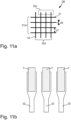
- the conductor tracks of the first electrically conductive layer and the second electrically conductive layer are structured, in particular structured such that the conductor tracks of the first electrically conductive layer and the second electrically conductive layer form a plurality of surface elements, preferably rhombus-shaped or diamond-shaped surface elements.
- the first and second electrically conductive layers may each have a so-called diamond structure. This diamond structure is formed by a plurality of, in particular, rhombus-shaped surface elements along linear conductor tracks.
- the first and second electrically conductive layers each have a plurality of spaced-apart diamond structures.
- the first and second electrically The conductive layers are arranged one above the other in such a way that both diamond structures are arranged at right angles to each other, i.e., rotated 90° to each other.
- the surface elements of the first electrically conductive layer are arranged "on gaps" in the free spaces between the surface elements of the second electrically conductive layer.
- the linear conductor tracks of the electrically conductive layers intersect in the spaces between the surface elements.
- a precise position of the surface elements relative to each other is particularly important, and the surface elements are advantageously arranged with a tolerance of less than 0.25 mm, preferably less than 0.1 mm, in register accuracy relative to each other, particularly in the direction of the x and y coordinates.
- the conductor tracks in the region of the surface elements can be shaped according to the shape of the surface elements, so that the material from which the electrically conductive layer is formed fills the surface elements over their entire surface. It is also possible for the conductor tracks to run along the surface elements, so that the conductor tracks frame the surface elements at least in certain areas.
- the surface elements can thus be formed from a full-surface conductive layer or from an electrically conductive layer that is only present in certain areas, in particular a gridded layer made up of conductive grid elements and in particular transparent, non-conductive surface areas between the grid elements.
- the grid forming the grid elements can be regular or irregular.
- the surface elements can be semi-transparent due to the gridding and have a surface coverage with grid elements of less than 50%.
- the electrically conductive structures of the first and second conductive layers formed by the structured electrically conductive layers and/or the conductive regions of the electrically conductive layers each have different geometries and/or sizes.
- the contacting areas, in particular the contacting structures, of the at least two electrically conductive layers are combined in a common contacting area. This makes it possible to facilitate external contacting.
- the common contacting area is electrically contacted by means of an adapter element.
- a particularly flexible adapter element to be attached to the common contacting area, which adapter element electrically contacts the contact points in the common contacting area and connects them externally in an electrically conductive manner to a further contact element.
- ACF Anisotropic Conductive Film
- the conductive adhesive can represent a connecting element.
- the conductor tracks are made of metal, in particular of silver (Ag), gold (Au), aluminum (Al), copper (Cu) or chromium (Cr) in a layer thickness between 1 nm and 100 nm, preferably between 2.5 nm and 75 nm, more preferably between 5 nm and 50 nm.
- the conductor tracks it is also possible for the conductor tracks to have a layer thickness between 100 nm and 5 ⁇ m.
- the conductor tracks are formed from an electrically conductive paste comprising silver (Ag), gold (Au), copper (Cu) and/or carbon.
- ITO and/or AZO layers are preferably applied over the entire surface by magnetron sputtering, sputtering, or (vacuum) vapor deposition, and less preferably by CVD and PVD processes, and preferably have a layer thickness of 1 nm to 100 ⁇ m, more preferably of 10 nm to 10 ⁇ m.
- the ITO and/or AZO layers are arranged directly adjacent to electrically conductive layers made of metallic materials.
- the at least one electrically conductive layer is a metal layer
- step b) further comprises the following steps: - vapor deposition of the metal layer; - structuring the metal layer by removing the metal layer in certain areas, in particular by means of photolithographic techniques.
- the carrier substrate is preferably provided with an electrically conductive layer over its entire surface, for example by vapor deposition or sputtering of a metal layer and then by positive or negative coating.
- the electrically conductive layer is removed again in certain areas by negative etching or by means of a washing process, corresponding to the formation of the electrical functional structure and contact structure.
- the at least one electrically conductive layer may be applied to the carrier substrate in the shape corresponding to the functional structure and/or contact structure by means of vapor deposition masks, by printing electrically conductive material, and/or by galvanically reinforcing a printed structure.
- the film comprises a dielectric layer and/or a semiconducting layer which is arranged between a first electrically conductive layer of the at least one electrically conductive layer and a second electrically conductive layer of the at least one electrically conductive layer.
- the at least one electrically conductive layer can have force sensors, in particular for measuring the compressive force.
- This makes it possible to generate x, y, and z information about the touch.
- the z information can be used, for example, to control an electrical functional element to which the film is applied, depending on whether a predefined threshold value of the z information is exceeded.
- Force sensors in particular for measuring the compressive force, are preferably piezoelectric thin films. It is also possible that Force sensors are piezoresistive pressure sensors and/or piezoelectric pressure sensors. Furthermore, force sensors can be actuators, in particular pushbuttons, where each of the actuators has at least two electrical states depending on the force acting on the actuators.
- the at least one electrically conductive layer may have surface relief structures, in particular matte structures, at least in some regions. This makes it possible to deflect light incident on the at least one electrically conductive layer by diffraction, scattering, and/or reflection, thus avoiding the impression that the electrically conductive layer reflects light, in particular in direct specular reflection.
- a display to which the film is applied appears homogeneously black when switched off.
- Layers with light-scattering properties are, for example, layers that have matte structures with stochastically selected relief parameters.
- the carrier substrate prefferably has a layer thickness between 2 ⁇ m and 250 ⁇ m, preferably between 23 ⁇ m and 125 ⁇ m.
- the carrier substrate it is also possible for the carrier substrate to have a layer thickness of less than 2 ⁇ m.
- the film has a total thickness of at most 150 ⁇ m, preferably 100 ⁇ m, more preferably 75 ⁇ m, perpendicular to the plane spanned by the underside of the carrier substrate.
- the carrier substrate is a transparent carrier substrate, in particular made of PET, PMMA, PC, acrylonitrile butadiene styrene (ABS), PU or glass.
- a transparent carrier substrate in particular made of PET, PMMA, PC, acrylonitrile butadiene styrene (ABS), PU or glass.
- the carrier substrate is formed from a hybrid material comprising plastic layers and layers of fiber material.
- the carrier substrate consists of fabrics, for example textile fabrics.
- the target substrate prefferably be a single- or multi-layer additional film.
- the application of the film according to the invention to the target substrate in the form of the single- or multi-layer additional film preferably produces an intermediate product for further processing.
- the film comprises at least one intermediate adhesive layer. This makes it possible to apply one or more additional layers to the film, with the adhesion of the one or more additional layers being achieved by the intermediate adhesive layer.
- the at least one electrically conductive layer is arranged between the carrier substrate and the at least one intermediate adhesive layer.
- the at least one intermediate adhesive layer may be arranged on the side of the carrier substrate facing away from the at least one electrically conductive layer.
- the method further comprise the following steps: f) applying an intermediate adhesive layer, in particular such that the at least one electrically conductive layer is arranged between the carrier substrate and the at least one intermediate adhesive layer and/or such that the at least one intermediate adhesive layer, when viewed perpendicular to a plane spanned by the carrier substrate, does not cover the at least one contacting region, at least in some regions.
- the at least one intermediate adhesive layer when viewed perpendicular to a plane spanned by the carrier substrate, does not cover the at least one contacting area, at least in part.
- the intermediate adhesive layer does not completely cover at least one contact area.
- the intermediate adhesive layer covers the functional area at least in part.
- the at least one intermediate adhesive layer is arranged substantially in the same region as the adhesion-promoting layer when viewed perpendicular to a plane spanned by the carrier substrate, in particular that the at least one intermediate adhesive layer is arranged substantially congruent with the adhesion-promoting layer when viewed perpendicular to a plane spanned by the carrier substrate.
- the intermediate adhesive layer has a layer thickness between 0.1 ⁇ m and 50 ⁇ m, preferably between 0.25 ⁇ m and 25 ⁇ m, more preferably between 0.5 ⁇ m and 7 ⁇ m.
- the intermediate adhesive layer is preferably a primer layer and/or adhesive layer made of a hot-melt adhesive, a cold-curing adhesive, or a radiation-curable adhesive, in particular an adhesive curable by electromagnetic radiation and/or electron beams.
- the intermediate adhesive layer is preferably applied using gravure printing, screen printing, letterpress printing, or casting techniques.
- the film prefferably includes one or more decorative layers.
- the one or more decorative layers are on the side of the carrier substrate facing away from the at least one electrically conductive layer arranged.
- the film can in particular have an intermediate adhesive layer to improve the adhesion of the one or more decorative layers.
- an intermediate adhesive layer can be applied to the carrier substrate and/or the at least one electrically conductive layer, by means of which the one or more decorative layers are applied to the carrier substrate.
- the decorative layers can then be applied to the intermediate adhesive layer or directly to the carrier substrate using various methods.
- the decorative layers have a protective layer as a final layer on the side of the carrier substrate facing away from the at least one electrically conductive layer, which protects the decorative layers in particular from the strong pressure and heat effects that occur, for example, during injection molding and/or lamination processes. Furthermore, the protective layer protects against mechanical damage that can occur during processing, such as scratches, etc.
- This protective layer can also contain polymeric and in particular self-supporting films, preferably made of PET, PC or PMMA, or also of glass or fabric, which remain on the decoration and form a component of the intermediate or final product.
- the one or more decorative layers are arranged substantially in the same region as the adhesion-promoting layer and/or the intermediate adhesive layer, in particular the one or more decorative layers are arranged substantially congruent with the adhesion-promoting layer and/or the intermediate adhesive layer when viewed perpendicular to a plane spanned by the carrier substrate.
- the one or more decorative layers prefferably be partially applied to the side of the carrier substrate facing away from the at least one electrically conductive layer in such a way that they cover substantially the same area as the adhesion promoter layer on the other side of the carrier substrate.
- the one or more decorative layers are arranged on the side of the adhesion-promoting layer and/or the intermediate adhesive layer facing away from the carrier substrate.
- the one or more decorative layers can be arranged on the side of the at least one electrically conductive layer facing away from the carrier substrate.
- the one or more decorative layers are preferably applied substantially congruently with the adhesion-promoting layer, leaving in particular the at least one contacting area uncovered.
- the decorative layers may have a protective layer as a final layer on the side of the at least one electrically conductive layer and/or the intermediate adhesive layer facing away from the carrier substrate, which protective layer protects the decorative layers in particular from the Protect against strong pressure and heat effects.
- the protective layer protects against mechanical damage that may occur during processing, such as scratches, etc.
- This protective layer can also contain polymeric and, in particular, self-supporting films, preferably made of PET, PC, or PMMA, or even glass or fabric, which remain on the decoration and form an integral part of the final product.
- the at least one intermediate adhesive layer is arranged between the carrier substrate and the one or more decorative layers.
- the one or more decorative layers comprise at least one of the layers selected from the group of protective layers, colored lacquer layers, metal layers, reflective layers, replication lacquer layers, transparent layers, carrier layers and/or layers generating an optically variable effect.
- the one or more decorative layers can comprise a printed layer, in particular made of an opaque and/or colored ink, which forms a frame around the functional area.
- the decorative layers can also fully or partially cover the film and in particular also the functional area and/or be applied in a grid.
- the decorative layers can represent a uniform surface and/or a continuous pattern and/or a single image motif.
- the decorative layers can be fully or partially opaque and/or semi-transparent and/or transparent, in particular colored transparent.
- one or more decorative layers can be applied, in particular embossed and/or printed, to the adhesion-promoting layer and/or the intermediate adhesive layer.
- the one or more decorative layers can be applied, for example, by hot stamping and/or cold stamping and/or by thermal transfer processes and/or by various lamination processes and/or other known processes to the side of the adhesion-promoting layer and/or the intermediate adhesive layer facing away from the carrier substrate.
- This makes it possible, for example, to provide the film with a decorative layer or decoration, so that the film, in addition to a function provided by the electrical functional structure in the form of a touch sensor field, also has a decoration.
- the one or more decorative layers can comprise further layers, such as protective lacquer layers and/or color layers and/or metal layers and/or transparent reflective layers and/or replication lacquer layers and/or various types of layer structures generating an optically variable effect.
- the layer structure of the film does not necessarily have to correspond to the layer structure according to claim 1.
- the one or more decorative layers comprise at least two decorative layers, in particular a first decorative layer and a second decorative layer.
- the one or more decorative layers can be arranged on the side of the carrier substrate facing away from the at least one electrically conductive layer and also on the side of the at least one electrically conductive layer facing away from the carrier substrate.
- a first decorative layer to be arranged on a first side of the carrier substrate and a second decorative layer is arranged on a side of the carrier substrate opposite the first side, so that the one or more decorative layers are arranged on both sides of the carrier substrate.
- the first decorative layer facing the viewer can represent a color filter layer for the second decorative layer facing away from the viewer, i.e., lying below it in the viewing direction, which can be, for example, a color layer.
- Overlay effects or combination effects are also possible using two patterns that complement each other to form a moiré pattern or that, when superimposed, result in other complementary combination patterns.
- optically variable combination effects are possible, which only arise through the superposition of at least two decorative layers.
- the decorative layers can be advantageous for the decorative layers to be spaced apart from one another, for example because, in particular, the carrier substrate and the electrically conductive layer and, if appropriate, further layers, in particular transparent layers, are arranged between the decorative layers.
- Such a spacing can be advantageous, in particular, for creating depth effects and/or optically variable effects.
- a depth effect can be created, for example, by inserting optically transparent layers in front of the decorative layers and/or behind the decorative layers and/or as a component of the decorative layers.
- the optically transparent layers preferably have the same layer thickness.
- the layer thickness of the optically transparent layers is between 0.5 ⁇ m and 500 ⁇ m, preferably between 10 ⁇ m and 100 ⁇ m.
- the optically transparent layers preferably consist of optically transparent lacquers and/or optically transparent films made of, preferably, PET, PMMA, or PC.
- An optically variable effect is possible, for example, by arranging the aforementioned optically transparent layer as a spacer layer between a reflective layer and a semitransparent reflective layer.
- interference effects occur that are recognizable by a viewing angle-dependent and/or illumination angle-dependent color change effect.
- Such interference layer structures are already known as Fabry-Perot thin-film structures.
- At least one of the one or more decorative layers has, at least in some areas, a surface relief structure, in particular a haptically and/or tactilely detectable surface relief structure.
- the optically transparent layers and/or the protective layers and/or the one or more decorative layers are created that enable particularly haptic or tactile effects.
- the surface relief structures can be created by additional partially printed lacquers or mechanical structuring or optical structuring. the layer surface.
- Mechanical structuring can be replication using a suitably shaped embossing tool.
- Optical structuring can be laser ablation. Photolithographic processes can also be used to create these structures.
- the structure depths for such haptic effects are in particular 1 ⁇ m to 2000 ⁇ m, preferably 50 ⁇ m to 2000 ⁇ m.
- the structure depths for diffractive or refractive effects are in particular 0.1 ⁇ m to 20 ⁇ m, preferably 0.1 ⁇ m to 5 ⁇ m.
- haptic surface relief structures are often mechanically sensitive, particularly to scratching and/or wear, and also become soiled more easily than smooth surfaces.
- a transparent cover layer can then be applied to this surface, which seals the haptic structure and has a smooth surface on the outside.
- This cover layer is preferably highly transparent and thicker than the height of the haptic structures, preferably at least twice as thick.
- the cover layer preferably has a refractive index that differs by at least 0.2 from that of the underlying layer containing the haptic structure, in order to create an optical interface, thereby increasing the visibility of the haptic structure.
- the cover layer can contain nanoscale particles for modulating the refractive index consisting of one or more components selected from TiO 2 , SiO 2 , Sn or metal chalcogenides (oxides, sulfides), as well as metals Au, Ag, Cu.
- the tactile and/or merely optically simulated haptic surface relief structure can correspond to the functional touch sensor fields, i.e., highlight or mark their functional area, enabling a "blind" perception of the touch function.
- the tactile and/or merely optically simulated haptic structure can be provided over the entire surface in order to achieve a specific surface characteristic of the target substrate, particularly matching its overall visual appearance. Both options can also be combined. For example, it is possible to combine a wood decor with a haptic wood grain that is modified in the area of the touch function, particularly in the functional area, in terms of structure depth and/or another structural parameter, so that the touch sensor field is tangible to a user within the grain.
- the film prefferably has an adhesive layer on the side of the carrier substrate facing away from the at least one electrically conductive layer.
- the film can thus have the adhesion-promoting layer on one side of the carrier substrate and the adhesive layer on the other side of the carrier substrate, so that the film can be applied to a further substrate by means of the adhesive layer.
- the film can be applied to the further substrate, for example, by hot lamination or by back-injection molding.
- the at least one electrically conductive layer and/or the one or more decorative layers are protected by the carrier substrate from the injected injection molding compound and in particular from the harsh process conditions of high pressure and high temperature during the injection molding process.
- the layer structure of the film does not necessarily have to correspond to the layer structure according to claim 1.
- the film has at least one register mark for determining the relative position of the film, in particular of the functional area and/or of the at least one contacting area of the at least one electrically conductive layer.
- Register or register accuracy is understood to mean the precise arrangement of layers lying one above or next to one another relative to one another while maintaining a desired positional tolerance.
- a register mark can ensure that the film can be applied to a target substrate in a precise position while maintaining a desired positional tolerance.
- the register mark is preferably formed from a printing material and/or from a magnetic or conductive material.
- the marks can thus be, for example, optically readable register marks that differ from the background in terms of their color value, their opacity or their reflective properties.
- the register marks can also be register marks that can be detected by a magnetic sensor or a sensor that detects electrical conductivity.
- the register marks are detected, for example, by an optical sensor, in particular a camera, a magnetic sensor or a mechanical sensor, a capacitive sensor, or a sensor that detects conductivity, and the application of the film can then be controlled using the register marks.
- the register marks thus enable the precise positioning of the film on the target substrate. This can improve identical manufacturing quality of touchscreens, for example, and at the same time further reduce rejection due to incorrect placement of the film on the target substrate.
- the film is a hot laminating film.
- step b) the film is applied from a roll to the target substrate by means of hot lamination, in particular at a film web speed of between 1.5 m/min and 3.5 m/min.
- the roll it is possible for the roll to comprise a film web with several or a plurality of films, in particular according to one of claims 1 to 53, as a panel.
- This makes it possible to further improve, in particular, industrial mass production.
- the film is applied from a sheet to the target substrate by means of hot lamination.
- the sheet it is possible for the sheet to comprise several or a plurality of films, in particular according to one of claims 1 to 53, as a panel. This makes it possible, in particular, to further improve industrial mass production. For example, it is possible to apply the film over the entire surface of a target substrate using a hot lamination machine, thus further reducing the time, personnel, and logistical expenditure while simultaneously ensuring identical manufacturing quality.
- the sheet can contain only one film.
- Several such sheets, each with one film, can be stacked in a magazine and individually fed to a hot laminating machine, which can operate using a stroke or roll-off process, and/or an injection molding machine for application to the target substrate.
- the registration marks on the film then ensure precise positioning on the target substrate, as described above.
- an intermediate substrate which can be in the form of a roll or a sheet, before application to the target substrate.
- the intermediate substrate can be, for example, a silicone-coated paper or a film web provided with a release layer.
- one or more films can then be transferred jointly or separately from the intermediate substrate to the target substrate by applying heat and/or pressure.
- the intermediate substrate can then be peeled off, particularly from the film firmly adhering to the target substrate.
- the hot lamination may take place at a temperature in the range between 80°C and 300°C, preferably between 200°C and 290°C, more preferably between 240°C and 270°C, and/or with an embossing pressure in the range between 200 bar and 2000 bar, preferably between 500 bar and 1500 bar.
- step b it is also possible to apply the film to the target substrate by injecting an injection-molding compound, with the injection-molding compound forming the target substrate. This allows the film to be firmly bonded to the injection-molding compound by the adhesion-promoting layer.
- the film it is also possible for the film to be bonded to another substrate by injecting an injection-molding compound.
- the layer structure of the film does not necessarily have to correspond to the layer structure according to claim 1.
- step b) the film is applied to the target substrate by hot stamping.
- the film can be applied to the target substrate from a roll or from a sheet by hot stamping.
- the roll prefferably comprises a film web with several or a plurality of films as panels, and/or for the sheet to comprise several or a plurality of films as panels.
- This makes it possible to further improve, in particular, industrial mass production. For example, it is possible to apply the film over the entire surface of a target substrate using a hot stamping machine, thus further reducing the time, personnel, and logistical effort while ensuring consistent manufacturing quality.
- the embossing temperature is in a range from 80°C to 250°C, preferably in a range from 100°C to 200°C, and/or the embossing pressure is in a range from 0.5 kN/cm 2 to 10 kN/cm 2 .
- the embossing time is in a range from 1 ms to 2000 ms, preferably in a range from 1 ms to 500 ms.
- the further substrate and/or the target substrate is flat and/or has a one-dimensionally curved and/or a two-dimensionally curved and/or a three-dimensionally curved shape.
- the film and/or the electrical functional element in particular the electrical functional element formed from the target substrate and the film, to be formed, in particular three-dimensionally formed.
- the forming advantageously takes place by means of forming processes, preferably by means of deep drawing, thermoforming, high-pressure forming, and/or by means of an injection molding process.
- the target substrate and/or intermediate substrate preferably has a layer thickness of a maximum of 1 mm, preferably 500 ⁇ m, so that the electrical functional element formed from the film and the target substrate is formable.
- the film and/or the electrical functional element are formed from the film arranged, in particular applied, on a target substrate:
- the film and/or the electrical functional element are formed by deep drawing.
- the forming of the film and/or the electrical functional element is carried out using a vacuum, in particular at a negative pressure of no more than 1 bar, and/or by means of overpressure support, in particular at an overpressure between 1 bar and 3 bar, in a forming tool corresponding to the desired forming geometry.
- the film and/or the electrical functional element may be formed by thermoforming.
- the forming process of the film and/or the electrical functional element, or the process parameters of the forming process correspond to those of deep drawing, with the forming taking place with additional temperature support, in particular at a temperature between 120°C and 300°C, preferably between 190°C and 250°C, for example, when using ABS material.
- additional temperature support in particular at a temperature between 120°C and 300°C, preferably between 190°C and 250°C, for example, when using ABS material.
- the carrier substrate and/or the target substrate to comprise ABS material.
- the film and/or the electrical functional element is formed by means of high-pressure forming.
- the forming of the film and/or the electrical functional element is carried out with the aid of overpressure, in particular at an overpressure between 1 bar and 300 bar, preferably between 10 bar and 150 bar, in a forming tool corresponding to the desired forming geometry.
- the forming is carried out with additional temperature support, preferably at temperatures in the range of the glass transition temperature of the film used. The temperature is advantageously between 120 °C and 300 °C, preferably between 190 °C and 250 °C, for example when using ABS material.
- strains of up to 200% are preferably achieved. It is also possible, especially when the parameters are optimized for the respective system, to achieve strains of up to 300%, although strains between 20% and 50% are sufficient in many applications.
- the films and/or electrical functional elements formed or preformed by means of the above-mentioned forming processes are pre-injected and/or back-injected in a subsequent injection molding process.
- the film and/or the electrical functional element is formed and/or deformed by means of an injection molding process.
- the film and/or the electrical functional element is introduced into the injection mold in a flat state via a roll, sheet, or individual label and deformed by means of the injection molding process, in particular wherein the shaping takes place by closing the tool and also by injecting the molding compound.
- the injection pressure depends on the component geometry and/or the component size. For example, it is possible for the injection pressure to be 500 bar and the injection temperature to be between 180 °C. and 380 °C, whereby the injection pressure and injection temperature depend on the injection molding material.
- the film and/or the electrical functional element introduced into the injection mold and/or the electrical functional element may be heated before the closing process of the injection mold by heating the film and/or the electrical functional element, for example at temperatures between 30 °C and 300 °C, preferably between 80 °C and 150 °C. It is also possible for the film and/or the electrical functional element to be fitted or fixed in the cavity by means of a clamping frame and/or vacuum and/or overpressure.
- the "covering" of the film and/or the electrical functional element is carried out by controlling a vacuum suction of the film and/or the electrical functional element onto the already three-dimensionally preformed component while simultaneously applying overpressure in a single process.
- the already three-dimensionally preformed component to be covered is previously subjected to a temperature. It is expedient if the overpressure is between 1 bar and 50 bar, preferably between 3 bar and 15 bar, and/or the temperature is between 30 °C and 300 °C, preferably between 100 °C and 180 °C.
- the film and/or the electrical functional element has an extensibility of greater than 20%.
- Such high extensibility cannot be achieved, for example, by means of the above-mentioned forming and/or deforming processes with conventional functional films, in particular because the carrier film made of, for example, PET, is not deformable. is sufficient and/or the conductive structures break after only slight deformation, particularly at elongations of more than 20%. It has been shown here that the elongation is improved by the film according to the invention.
- the multi-layer structure of the film according to the invention in particular by the at least one electrically conductive layer embedded between several layers of lacquer according to a sandwich system, as described above, means that the mechanical elongation and/or deformation can be influenced in a targeted manner, for example by adjusting the layer thicknesses and/or the lacquer formulations to make certain areas of the film more or less flexible.
- the desired elongation of more than 20% is thus preferably achieved here.
- the electrical functional structure of the film and/or the electrical functional element can be electrically contacted from the outside, in particular galvanically, for which the electrical contacts must be accessible for contacting.
- inductive and/or capacitive coupling in particular coupling via an antenna, can be implemented.
- the film according to the invention enables robust and secure contacting of the electrical functional structure.
- the adhesion-promoting layer may consist of a material whose optical appearance changes from cloudy to highly transparent and/or clear during and/or after step b).
- the adhesion-promoting layer is melted due to the applied heat during application of the film to the target substrate. and/or the adhesion-promoting layer is leveled by pressure, so that the surface roughness of the adhesion-promoting layer present in the unapplied state of the film is leveled during and/or after application. This changes the optical appearance of the adhesion-promoting layer from cloudy to highly transparent and/or clear.
- the film After application of the film to a target substrate, the film forms an electrical functional element with the target substrate.
- the adhesion-promoting layer of the film is highly transparent; in particular, the adhesion-promoting layer of the film has a light transmission in the wavelength range between 380 nm and 780 nm of more than 85%, preferably more than 90%, and/or the adhesion-promoting layer of the film is a clear adhesion-promoting layer; in particular, light in the wavelength range between 380 nm and 780 nm is deflected by the adhesion-promoting layer of the film by less than 8%, preferably by less than 4%, through scattering.
- the film at least in the one functional region of the at least one electrically conductive layer, to have a light transmission in the wavelength range between 380 nm and 780 nm of more than 75%, preferably more than 80%, more preferably more than 85%, even more preferably more than 90%. This makes it possible, for example, to achieve a brilliant and true-to-original viewing of an image generated by a display to which the film is applied.
- the electrical functional element is a functional element for information processing, in particular a mobile phone, such as a smartphone or a PDA, a tablet computer, an ATM, a ticket machine, a gaming machine, a gaming console, a control panel of a household appliance or a motor vehicle, or, for example, a touchscreen.
- a mobile phone such as a smartphone or a PDA, a tablet computer, an ATM, a ticket machine, a gaming machine, a gaming console, a control panel of a household appliance or a motor vehicle, or, for example, a touchscreen.
- the electrical functional element to be an input device, in particular a touch panel.
- the electrical functional element it is also possible for the electrical functional element to be an intermediate product that is incorporated into or in a final product in further processing steps.
- the film can be applied to a glass layer, and the electrical functional element formed from the glass layer and the film can be incorporated into a ticket machine, for example.
- Fig. 1a shows a film 1 with a carrier substrate 2, an electrically conductive layer 3 and an adhesion-promoting layer 4.
- the carrier substrate 2 is preferably a layer of PET, PMMA, PC, ABS, PU, glass, or fabric. It is also possible for the carrier substrate 2 to be formed from a hybrid material comprising plastic layers and layers of fabric, in particular fiber material, such as paper, cotton, or other natural or synthetic fibers.
- the carrier substrate 2 preferably has a layer thickness between 2 ⁇ m and 250 ⁇ m, preferably between 23 ⁇ m and 125 ⁇ m.
- Fig. 1a The carrier substrate 2 shown is a transparent layer of PET with a layer thickness of 75 ⁇ m.
- the electrically conductive layer 3 is preferably a layer of metal, in particular of silver (Ag), gold (Au), aluminum (Al), copper (Cu) or chromium (Cr).
- the electrically conductive layer 3 preferably has a layer thickness between 1 nm and 100 nm, more preferably between 2.5 nm and 75 nm, even more preferably between 5 nm and 50 nm. It is also possible for the layer thickness of the electrically conductive layer 3 to be between 100 nm and 5 ⁇ m.
- the electrically conductive layer 3 can further be formed from an electrically conductive paste comprising silver (Ag), gold (Au), copper (Cu) and/or carbon.
- the electrically conductive layer 3 shown is a layer of Ag with a layer thickness of 50 nm.
- the electrically conductive layer 3 is formed such that the electrically conductive layer 3 has a plurality of conductor tracks which have a width 26 between 0.2 ⁇ m and 20 ⁇ m, preferably between 4 ⁇ m and 15 ⁇ m, and a distance 27 greater than 10 ⁇ m, preferably greater than 20 ⁇ m, from one another, so that the conductor tracks are below the resolution of the human eye.
- Conductor tracks are understood here to mean preferably structured electrically conductive layers and conductive regions of the at least one electrically conductive layer 3.
- the conductor tracks are applied such that sufficient transparency for the human eye is maintained; i.e., the conductor tracks are designed such that they are not perceived by a human observer, since the conductor tracks are below the resolution of the human eye.
- the coverage of the carrier substrate 2 with the at least one electrically conductive layer 3, in particular the conductor tracks is less than 30%, preferably less than 20%, more preferably less than 10%, even more preferably less than 5%.
- the width 26 of the conductor tracks formed by the electrically conductive layer 3 is 5 ⁇ m and the distance 27 of the conductor tracks formed by the electrically conductive layer 3 is 15 ⁇ m.
- the adhesion-promoting layer 4 is preferably a layer of polymers and/or copolymers, in particular comprising PMMA, polyester, PU or PVC, with a layer thickness between 0.1 ⁇ m and 50 ⁇ m, preferably between 0.25 ⁇ m and 25 ⁇ m, more preferably between 0.5 ⁇ m and 7 ⁇ m.
- the adhesion-promoting layer 4 shown is a layer of PVC copolymers with a layer thickness of 4 ⁇ m.
- the electrically conductive layer 3 is arranged between the carrier substrate 2 and the adhesion-promoting layer 4.
- the adhesion-promoting layer 4 is thus arranged on the side of the at least one electrically conductive layer 3 facing away from the carrier substrate 2.
- the film 1 has a top side 40 and a bottom side 41, with the adhesion-promoting layer 4 being arranged on the top side 40.
- the adhesion-promoting layer 4 is arranged on the surface of the film 1.
- the adhesion-promoting layer 4 is arranged in the region 22.
- the region 22 covers the functional structure formed by the electrically conductive layer 3 in the functional region 21 in Fig. 1a Completely.
- the adhesion-promoting layer 4 is not arranged in the region 23.
- the region 23 encompasses the contacting region 20 of the electrically conductive layer 3, so that the adhesion-promoting layer 4 does not fully cover the contacting region 20.
- the film 1 is applied to a target substrate, the region 23 does not adhere to the target substrate, and therefore, in particular, the contacting region 20 is accessible after the film 1 has been applied to the target substrate, and the electrical functional structure can be reliably contacted.
- the adhesion-promoting layer 4 does not completely cover the functional area 21.
- the adhesion-promoting layer 4 can cover the functional area 21 to at least 30%, preferably at least 50%, more preferably at least 70%.
- the adhesion-promoting layer 4 preferably consists of a material that is highly transparent after the film 1 has been applied to a target substrate.
- the term "highly transparent” describes the property of a material that barely attenuates light from the wavelength range visible to the human eye, in particular from the wavelength range between 380 nm and 780 nm, and allows it to pass through essentially unhindered. A highly transparent layer therefore exhibits essentially no discernible light absorption for a human observer, so that the light intensity is barely discernibly reduced when the light passes through the layer.
- the adhesion-promoting layer 4 preferably consists of a material which, after application to the target substrate, has a transmission of light in the wavelength range between 380 nm and 780 nm of more than 85%, preferably more than 90%.
- the adhesion-promoting layer 4 consists of a material which is clear after application of the film 1 to a target substrate, so that light in the wavelength range between 380 nm and 780 nm is deflected by less than 8%, preferably by less than 4%, by scattering from the adhesion-promoting layer 4 after application of the film 1 to the target substrate.
- the adhesion-promoting layer 4 in the state not yet applied to the target substrate, can in particular have light-scattering properties due to surface roughness of the adhesion-promoting layer 4, which for example, due to traces of the process steps for applying the adhesion-promoting layer 4.
- the adhesion-promoting layer 4 becomes highly transparent and/or clear in particular when the film 1 is applied to the target substrate and the adhesion-promoting layer 4 is melted and/or leveled, for example, by means of heat and/or pressure applied during hot lamination, so that the surface roughness of the adhesion-promoting layer 4 no longer has a disruptive appearance. This means that the adhesion-promoting layer 4 becomes highly transparent and/or clear due to physical and/or chemical changes in the adhesion-promoting layer 4 during or after the application of the film 1 to the target substrate.
- Fig. 1b shows a film 1 comprising a carrier substrate 2, an electrically conductive layer 3, a protective lacquer layer 6, a contact reinforcement layer 7 and an adhesion-promoting layer 4.
- the protective lacquer layer 6 is preferably a layer of PMMA, polyester, PU or PVC with a layer thickness between 0.1 ⁇ m and 50 ⁇ m, preferably between 0.25 ⁇ m and 25 ⁇ m, more preferably between 0.5 ⁇ m and 15 ⁇ m.
- Fig. 1b The protective lacquer layer 6 shown is a transparent layer of PAC with a layer thickness of 5 ⁇ m.
- the protective lacquer layer 6 covers the electrically conductive layer 3, but not the contacting area 20.
- the protective lacquer layer 6 covers the functional area 21 formed by the electrically conductive layer 3, but not the contacting area 20.
- the protective lacquer layer 6 is, as in Fig. 1b shown, arranged on the side of the electrically conductive layer 3 facing away from the carrier substrate 2. The protective lacquer layer 6 is thus arranged between the electrically conductive layer 3 and the adhesion-promoting layer 4.
- the contact reinforcement layer 7 is preferably a layer of an electrically conductive paste, in particular carbon paste, comprising silver (Ag), gold (Au), aluminum (Al), copper (Cu), chromium (Cr), and/or other conductive metals.
- the electrically conductive paste, in particular carbon paste may comprise binders, in particular rosin and/or phenolic resins, polymers, and copolymers.
- Binders are substances that can bind solids, especially those with a fine degree of particle size, together or to a substrate. Thus, binders can be added in liquid form to the solids to be bound.
- Binders of the electrically conductive paste, in particular carbon paste are natural resins, preferably rosin, phenolic resins, polymers and copolymers consisting of PVC, PMMA, PU, polyester, isocyanate (NCO)-crosslinked binders, for example MF, MPF, melamine-polyester, UMF. Less preferred are binders of the electrically conductive paste comprising Poly(organo)siloxanes and their copolymers and/or radiation-curing binders.
- paints and pastes can be solvent-based or water-based in the form of an emulsion, dispersion or suspension.
- the contact reinforcement layer 7 preferably has a layer thickness between 0.1 ⁇ m and 100 ⁇ m, preferably between 0.25 ⁇ m and 25 ⁇ m, more preferably between 0.5 ⁇ m and 10 ⁇ m.
- the contact reinforcement layer 7 shown is a layer of a carbon paste with a layer thickness of 4.5 ⁇ m.
- the contact reinforcement layer 7 is applied in the contacting region 20 of the electrically conductive layer 3.
- the electrically conductive layer 3 has the contact reinforcement layer 7 in the contacting region 20.
- the contact reinforcement layer 7 is applied over the entire surface of the contacting region.
- the contact reinforcement layer 7 protects the contacting region 20 or the contact structure formed in the contacting region 20 from mechanical, physical, and/or chemical environmental influences.
- the adhesion-promoting layer 4 is, as in Fig. 1b shown, present in the region 22 and not present in the region 23.
- the adhesion-promoting layer 4 when viewed perpendicular to a plane spanned by the carrier substrate 2, is thus in the region 24, which is separated from the region 23 is included, is not present.
- the region 24 borders on the contacting region 20 and does not have the adhesion-promoting layer 4.
- the adhesion-promoting layer 4 is only applied in the region 22 and does not cover the region 24 bordering the contacting region 20.
- the film 1 When the film 1 is applied to a target substrate, the film 1 therefore only adheres to the target substrate in the region 22.
- the region 23 which includes the regions 20 and 24, the film 1 does not adhere to the target substrate, so that the contacting region 20 is accessible.
- the region 23 can be raised, wherein the region 24 bordering the contacting region 20, for example, performs a hinge function for lifting the region 23.
- the region 24 preferably has a width of at least 0.2 mm, preferably of at least 0.5 mm, more preferably of at least 1 mm, even more preferably of at least 2 mm.
- Fig. 1b The region 24 shown has a width of 1 mm.
- the width of the region 24 can be selected depending on the requirements of the target substrate to which the film 1 is to be applied, or depending on the further processing step after application of the film 1 to the target substrate. Width here refers to the distance between the interface 42, which is formed by the contacting region 20 and the region 24 adjacent to the contacting region 20, and the interface 43, which is formed by the adhesion-promoting layer 4 and the region 24 adjacent to the contacting region 20.
- Fig. 1c shows a film 1 with a carrier substrate 2, an electrically conductive layer 3, an adhesion-promoting layer 4, a release layer 5, a protective lacquer layer 6, and a contact-reinforcing layer 7.
- the release layer 5 is preferably a layer made of waxes, polyethylene (PE), polypropylene (PP), cellulose derivatives, or poly(organo)siloxanes.
- the aforementioned waxes can be natural waxes, synthetic waxes, or combinations thereof. Examples of the aforementioned waxes include carnauba waxes. Examples of the aforementioned cellulose derivatives include cellulose acetate (CA), cellulose nitrate (CN), cellulose acetate butyrate (CAB), or mixtures thereof.
- the release layer 5 preferably has layer thicknesses between 0.1 ⁇ m and 10 ⁇ m, preferably between 0.01 ⁇ m and 5 ⁇ m. In the Fig. 1c The release layer 5 shown is a layer of a PE wax dispersion with a layer thickness of less than 1 ⁇ m.
- the release layer 5 covers, as in Fig. 1c shown, the area 24 adjacent to the contacting area 20 over the entire surface.
- the contacting area 20 is only partially covered by the release layer 5.
- the release layer it is also possible for the release layer to completely cover the contacting area 20. It is also possible for the release layer to be applied over the entire surface or at least partially in the contacting area 20, but not in the area 24 adjacent to the contacting area 20.
- the release layer 5 prevents the areas to which the release layer 5 is applied from adhering to a target substrate onto which the film 1 is applied. This way, the Fig. 1c The film 1 shown in the region 22 after application to a target substrate adheres to the target substrate, but not in the region 23, which comprises the regions 20 and 24. The release layer 5 can thus ensure that the regions which have the release layer 5 do not adhere to the target substrate, for example by hot lamination to a target substrate.
- the film 1 after application to a target substrate, has in the functional area formed by the electrically conductive layer 3 at least a transmission of light in the wavelength range between 380 nm and 780 nm of more than 75%, preferably more than 80%, more preferably more than 85%, even more preferably more than 90%.
- the transmittance describes the permeability of film 1 for light in the wavelength range between 380 nm and 780 nm.
- Light incident on film 1 is partially reflected at the interface between air and film 1 and at the interfaces between the layers of film 1. Furthermore, the light incident on film 1 is partially absorbed as it passes through film 1. The remaining portion of the light is transmitted through film 1 and exits on the opposite side of film 1.
- the transmittance ⁇ is a measure of the "transmitted" intensity and takes values between 0 and 1. The transmittance is typically dependent on the wavelength of the incident light.
- the adhesion-promoting layer 4 may have a cloudy visual impression prior to application of the film 1 to a target substrate, which is caused in particular by surface roughness of the adhesion-promoting layer 4.
- these surface roughnesses are leveled, for example, by heat applied during the application process, which melts the adhesion-promoting layer 4, and/or by pressure exerted, which levels the adhesion-promoting layer by pressing it against the target substrate.
- the adhesion-promoting layer becomes highly transparent and/or clear, particularly after application to the target substrate, so that the cloudy visual impression disappears and high transmission values of the applied film 1 can be achieved. Therefore, the transmission of the film 1 is preferably measured after application to a target substrate, as explained below.
- the total transmittance is 84.6%.
- This total transmittance is obtained both from the side of the PMMA target substrate 10 and from the side of the carrier substrate 2 of film 1.
- the PMMA target substrate exhibits a transmittance of 93.6%.
- the Byk Gardener Haze-Gard Plus measuring device from BYK-Gardner GmbH, Geretsried, Germany, was used to measure the total transmittance and the transmittance of the PMMA target substrate.
- Fig. 1d shows a film 1 with a carrier substrate 2, an electrically conductive layer 3, an adhesion-promoting layer 4, a release layer 5, a protective lacquer layer 6 and a contact-reinforcing layer 7.
- the Fig. 1d Slide 1 shown corresponds to the one in Fig. 1c shown film with the difference that the protective lacquer layer 6 in Fig. 1d with a greater layer thickness.
- Fig. 1d The protective lacquer layer 6 shown has a layer thickness of 10 ⁇ m.
- Fig. 1e shows a film 1 with a carrier substrate 2, a first electrically conductive layer 3a, a protective lacquer layer 6, a second electrically conductive layer 3b, an adhesion-promoting layer 4, a release layer 5 and a contact-reinforcing layer 7.
- the first electrically conductive layer 3a is formed such that the first electrically conductive layer 3a has a plurality of conductor tracks that run in the y-direction and are strip-shaped.
- the second electrically conductive layer 3b is formed such that the second electrically conductive layer 3b has a plurality of conductor tracks that run in the x-direction and are also strip-shaped.
- the conductor tracks of the first electrically conductive layer 3a can be designed as sensor conductor tracks, and the conductor tracks of the second electrically conductive layer can be designed as driver conductor tracks, wherein the first electrically conductive layer 3a is electrically insulated from the second electrically conductive layer 3b by the protective lacquer layer 6.
- the conductor tracks of the first and second electrically conductive layers can be diamond-shaped. Furthermore, it is possible for the conductor tracks of the first electrically conductive layer 3a form the y-sensors of a touch sensor, and the conductor tracks of the second electrically conductive layer 3b form the x-sensors of the touch sensor. It is also possible for the conductor tracks of the first electrically conductive layer and the conductor tracks of the second electrically conductive layer to be shaped differently, in particular for the conductor tracks to have different widths and/or different spacings. Regarding the further design of the conductor tracks, reference is made to the above explanations.
- the film 1 has the adhesion-promoting layer 4 in the region 22 and not in the region 23.
- the release layer 5 is further applied to the contact-reinforcing layer 7 in the contacting region 20, wherein the release layer completely covers the contacting region 20.
- the film 1 adheres to the target substrate in the region 22, and in the region 23, which encompasses the region 20, the film 1 does not adhere to the target substrate, so that the contacting region 20 is accessible.
- Fig. 1f shows a film 1 with a carrier substrate 2, a first electrically conductive layer 3a, a dielectric layer 8, a second electrically conductive layer 3b, a protective lacquer layer 6, an adhesion-promoting layer 4, a release layer 5 and a contact-reinforcing layer 7.
- a dielectric layer 8 is arranged between the first electrically conductive layer 3a and the second electrically conductive layer 3b.
- the dielectric layer is preferably a layer of PE, PTFE or ceramic with a layer thickness between 0.1 ⁇ m and 100 ⁇ m, preferably between 0.25 ⁇ m and 25 ⁇ m, more preferably between 0.5 ⁇ m and 10 ⁇ m.
- the dielectric layer shown is a PE layer with a layer thickness of 6 ⁇ m. It is also possible that layer 8 is a semiconducting or insulating layer.
- the film 1 has the adhesion-promoting layer 4 in the area 22 and not in the area 23.
- the release layer 5 is, as in Fig. 1f shown, present both in the contacting region 20 and in the region 24 adjacent to the contacting region 20.
- the release layer is applied over the entire surface in regions 20 and 24.
- the film 1 adheres to the target substrate in region 22, and in region 23, which comprises regions 20 and 24, the film 1 does not adhere to the target substrate, so that the contacting region 20 is accessible.
- the film 1 can be lifted in region 23 after application to the target substrate, so that secure and robust contact is enabled.
- the region 24 can serve as a movable hinge to lift the contacting region 20.
- Fig. 2a and Fig. 2b show further embodiments of the film 1 according to the invention, which comprise a carrier substrate 2, an electrically conductive layer 3 and an adhesion-promoting layer 4.
- the electrically conductive layer 3 in Fig. 2a is, for example, a metal layer made of aluminum, which is initially applied in regions over the entire surface of the carrier substrate 2. Subsequently, the surface relief structures of the metal layer 3 can be created by etching the metal using acid, by laser structuring the surface, or by mechanical surface treatment.
- the aforementioned laser structuring of the surface is carried out, for example, by removal, in particular ablation, of the metal on the surface of the metal layer using a solid-state laser, such as an Nd:YAG laser.
- the aforementioned mechanical surface treatment preferably involves rubbing, sanding, brushing, or similar mechanical roughening processes.
- Such a surface treatment of the metal layer can be carried out over the entire surface of the entire metal layer 3 or only in certain regions.
- Fig. 2a The metal layer 3 has surface relief structures throughout the entire functional area 21, but not in the contacting area 20. After the surface treatment, the metal layer 3 is structured to create the conductor tracks.
- the metal layer 3 can be structured, for example, by demetallization processes such as etching or washing, i.e., removed in certain areas to create the conductor tracks.
- the adhesion-promoting layer 4 is present in the region 22 and not present in the region 23, so that the film 1, after application to a target substrate, adheres to the target substrate in the region 22 and does not adhere to the target substrate in the region 23, which includes the contacting region 20.
- the contacting region 20 is thus accessible after application to the target substrate.
- the Fig. 2b Slide 1 shown corresponds to the one in Fig. 2a shown film 1 with the difference that the electrically conductive layer 3 does not have any surface relief structures, but rather that a darkening layer 9 is applied to the electrically conductive layer 3.
- the darkening layer 9 is preferably a layer of a dark color which absorbs light incident on the darkening layer 9.
- the darkening layer 9 can be applied using conventional coating methods, such as printing, doctor blade coating, or spin coating.
- the electrically conductive layer 3 and the carrier substrate 2 can also have different wettability, for example, wherein the wettability of a color varnish providing the darkening layer 9 is selected such that it adheres well exclusively to the conductor tracks formed by the electrically conductive layer 3.
- the darkening layer 9 can also be selectively applied to the conductor tracks using a thermal transfer method.
- the conductor tracks can be selectively heated by a lamp, with molten coloring material preferentially depositing on the heated conductor tracks.
- layer 9 it is also possible for layer 9 to be a layer with light-scattering properties.
- the layer with light-scattering properties preferably has a surface relief structure, in particular a matte structure with stochastically selected relief parameters.
- layer 9 it is also possible for layer 9 to be a layer having light-absorbing surface relief structures, such as moth-eye structures.
- Fig. 3 shows a film 1 with a carrier substrate 2, an electrically conductive layer 3, an intermediate adhesive layer 11, the decorative layers 12a and 12b, an adhesion-promoting layer 4, a release layer 5 and a contact-reinforcing layer 7.
- the intermediate adhesive layer 11 is, as in Fig. 3 shown, arranged on the side of the electrically conductive layer facing away from the carrier substrate 2. Furthermore, the intermediate adhesive layer 11 covers the functional region 21 formed by the electrically conductive layer 3, but not the contacting region 20. Furthermore, the intermediate adhesive layer 11 is arranged between the electrically conductive layer and the first decorative layer 12a.
- the intermediate adhesive layer 11 is preferably a primer layer and/or an adhesive layer made of a hot-melt adhesive, a cold-melt adhesive, or a radiation-curable adhesive, in particular an adhesive curable by means of electromagnetic radiation and/or electron beams. It is also possible for the intermediate adhesive layer 11 to comprise PMMA, polyester, PU, or PVC.
- the intermediate adhesive layer 11 is preferably applied by means of gravure printing, screen printing, letterpress printing, or casting techniques in a layer thickness between 0.1 ⁇ m and 50 ⁇ m, preferably between 0.25 ⁇ m and 25 ⁇ m, more preferably between 0.5 ⁇ m and 7 ⁇ m.
- Fig. 3 The intermediate adhesive layer 11 shown is a hot-melt adhesive layer with a layer thickness of 5 ⁇ m.
- the decorative layers 12a and 12b are arranged in the same area 22 as the adhesion-promoting layer 4, so that the decorative layers 12a and 12b, when viewed perpendicular to a plane spanned by the carrier substrate 2, are arranged congruently with the adhesion-promoting layer 4 and/or the intermediate adhesion layer 11. This ensures that the contacting area is accessible for secure and robust contacting of the electrical functional structure despite the additional decorative layers 12a and 12b.
- the decorative layer 12a shown is preferably a replication lacquer layer.
- the replication lacquer layer consists, for example, of a thermoplastic lacquer into which a surface relief structure is molded at least partially by means of heat and pressure through the action of an embossing tool.
- the replication lacquer layer it is also possible for the replication lacquer layer to be formed from a UV-crosslinkable lacquer and for the surface relief structure to be molded into the replication lacquer layer by means of UV replication.
- the surface relief structure is molded by the action of an embossing tool on the uncured replication lacquer layer and the replication lacquer layer is cured immediately during or after the molding by irradiation with UV light.
- the replication lacquer layer it is advantageous for the replication lacquer layer to have a layer thickness between 0.2 ⁇ m and 4 ⁇ m, preferably 0.3 ⁇ m and 2 ⁇ m, more preferably 0.4 ⁇ m and 1.5 ⁇ m.
- the decorative layer 12a shown is a replication lacquer layer made of a UV-crosslinkable lacquer with a layer thickness of 1.25 ⁇ m.
- the decorative layer 12b shown is preferably a reflective layer.
- the reflective layer is preferably a metal layer made of chromium, aluminum, gold, copper, silver or an alloy of such metals, which is vacuum-deposited in a layer thickness of 0.01 ⁇ m to 0.15 ⁇ m.
- the The reflective layer is formed by a transparent reflective layer, preferably a thin or finely structured metallic layer or a dielectric HRI or LRI layer ( high refraction index - HRI, low refraction index - LRI).
- Such a dielectric reflective layer consists, for example, of a vapor-deposited layer of a metal oxide, metal sulfide, e.g., titanium oxide, etc., with a thickness of 10 nm to 150 nm. Furthermore, it is also possible for the reflective layer to be implemented only in certain areas. Thus, it is possible for partial metallization to be present, which, for example, forms a metallic text or nanotext.
- Fig. 3 The decorative layer 12b shown is a metal layer made of copper with a layer thickness of 10 nm.
- Fig. 4a shows a film 1 with a carrier substrate 2, an electrically conductive layer 3, an intermediate adhesive layer 11, a decorative layer 12c, an adhesion-promoting layer 4 and a contact-reinforcing layer 7.
- the adhesion-promoting layer 4 is arranged on the side of the carrier substrate 2 facing away from the electrically conductive layer. Furthermore, the adhesion-promoting layer 4 is applied over the entire surface when viewed perpendicular to a plane spanned by the carrier substrate 2. However, it is also possible that the adhesion-promoting layer 4 is not arranged in the region 23a, which overlaps the contacting region 20 of the electrically conductive layer 3. Furthermore, the adhesion-promoting layer 4 comprises, as in Fig. 4a shown the layers 4a and 4b. This makes it possible to optimize the adhesion of the film 1 to a target substrate. Thus, layer 4a be optimized for the material of the carrier substrate 2 and the layer 4b be optimized for the material of the target substrate to which the film 1 is to be applied by means of the adhesion-promoting layer 4.
- the intermediate adhesive layer 11 is, as in Fig. 4a shown, arranged on the side of the electrically conductive layer 3 facing away from the carrier substrate 2. Furthermore, the intermediate adhesive layer 11 covers the functional region 21 formed by the electrically conductive layer 3, but not the contacting region 20. Furthermore, the intermediate adhesive layer 11 is arranged between the electrically conductive layer and the first decorative layer 12c.
- the decorative layer 12c is, as in Fig. 4a shown, are arranged in the same area as the intermediate adhesive layer 11, so that the decorative layer 12c, when viewed perpendicular to a plane spanned by the carrier substrate 2, is arranged congruently with the intermediate adhesive layer 11. This ensures, in particular, that the contacting area 20 can be contacted securely and robustly despite the additional decorative layer 12c.
- the decorative layer 12c is preferably a transparent colored lacquer layer.
- the decorative layer 12c contains dyes and/or pigments that impart a color filter effect to the decorative layer 12c, for example.
- the decorative layer 12c forms a pattern.
- a pattern can be, for example, a graphically designed outline, a figurative representation, an image, a motif, a symbol, a logo, a portrait, an alphanumeric This could be characters, text, etc. It's also possible for the pattern to have differently colored pattern elements.
- the decorative layer 12c can be a printed layer, in particular made of an opaque and/or colored ink.
- the printed layer can, for example, form a frame around the functional area 21 or be printed in a pattern, for example, in a linear pattern.
- Fig. 4b shows a film 1 with a carrier substrate 2, an electrically conductive layer 3, an intermediate adhesive layer 11, the decorative layers 12c and 12d, an adhesion-promoting layer 4 and a contact-reinforcing layer 7.
- the decorative layer 12d is preferably a transparent carrier layer made of PET, PMMA, PC, ABS, PU, glass, fabric, or a hybrid material comprising plastic layers and layers of fabric, in particular fiber material, such as paper, cotton, or other natural or synthetic fibers.
- the carrier layer preferably has a layer thickness between 2 ⁇ m and 250 ⁇ m, preferably between 23 ⁇ m and 125 ⁇ m.
- Fig. 4b The decorative layer 12d shown is a transparent layer of PET with a layer thickness of 25 ⁇ m. As shown in Fig. 4b
- the decorative layer 12d is also shown to be arranged congruently with the intermediate adhesive layer 11, so that the contacting area remains accessible and the electrical functional structure can be contacted safely and robustly.
- Fig. 4c shows a film 1 with a carrier substrate 2, an electrically conductive layer 3, an intermediate adhesive layer 11, the decorative layers 12c, 12d and 12e, an adhesion-promoting layer 4 and a contact-reinforcing layer 7.
- the decorative layer 12e is preferably a transparent colored lacquer layer.
- the decorative layer 12e contains dyes and/or pigments, which impart a color filter effect to the decorative layer 12e, for example. If, for example, the decorative layer 12c is also formed as a transparent colored lacquer layer, as explained above, the interaction of the two decorative layers 12c and 12e creates a color filter effect, in particular a color mixing effect, for the viewer. However, it is also possible, for example, for the decorative layer 12c and the decorative layer 12e to be printed layers, each forming a pattern. The two decorative layers 12c and 12e can interact with each other in such a way that a moiré effect is created for the viewer and thus a predetermined moiré pattern becomes recognizable.
- the decorative layer 12d can serve, for example, as a transparent spacer layer.
- the decorative layer 12e is also, as in Fig. 4b shown, arranged congruently with the intermediate adhesive layer 11, so that the contacting area remains accessible.
- Fig. 5a shows a film 1 with a carrier substrate 2, an electrically conductive layer 3, an intermediate adhesive layer 11, the decorative layers 12c, 12d and 12f, an adhesion-promoting layer 4 and a contact-reinforcing layer 7.
- the adhesion-promoting layer 4 can, as in Fig. 5a shown, be applied over the entire surface. However, it is also possible for the adhesion-promoting layer 4 to be absent in the region 23a. This further improves the accessibility of the contacting area, since the corresponding surface area 23a remains free on both sides, which can be electrically contacted in a particularly simple manner in subsequent processing steps, for example by means of a plug connection.
- the decorative layer 12f is preferably an optically transparent lacquer layer that is partially printed.
- the decorative layer 12f creates a haptic and/or tactile effect due to the surface relief structures.
- the decorative layer 12f can therefore be perceived haptically and/or tactilely.
- the surface relief structures of the decorative layer 12f can create diffractive and/or refractive optical effects.
- the surface relief structures can be created by mechanical structuring or optical structuring, in particular by means of a laser, of the layer surface. Mechanical structuring can be replication using a correspondingly shaped embossing tool.
- Optical structuring can be laser ablation.
- photolithographic processes can also be used to create these structures.
- the structural depths of the surface relief structures for haptic and/or tactile detection are preferably between 1 ⁇ m and 2000 ⁇ m, more preferably between 50 ⁇ m and 2000 ⁇ m.
- Structural depths for Diffractive or refractive effects are preferably between 0.1 ⁇ m and 20 ⁇ m, more preferably 0.1 ⁇ m and 5 ⁇ m.
- the decorative layer 12f is arranged on the decorative layer 12d. Furthermore, the decorative layers 12c, 12d, and 12f are arranged on the same side of the carrier substrate 2.
- Fig. 5b shows a film 1 with a carrier substrate 2, an electrically conductive layer 3, an intermediate adhesive layer 11, the decorative layers 12c, 12d, 12e and 12f, an adhesion-promoting layer 4 and a contact-reinforcing layer 7.
- Fig. 5c shows a film 1 with a carrier substrate 2, an electrically conductive layer 3, an intermediate adhesive layer 11, the decorative layers 12a, 12b and 12f, an adhesion-promoting layer 4, a release layer 5 and a contact-reinforcing layer 7.
- the decorative layer 12f is arranged on the side of the carrier substrate 2 facing away from the electrically conductive layer 3.
- the decorative layers 12a and 12b are arranged on the side of the carrier substrate 2 facing the electrically conductive layer 3 and on the side of the electrically conductive layer 3 facing away from the carrier substrate 2, respectively.
- Fig. 6a shows a film 1 with a carrier substrate 2, an electrically conductive layer 3, an intermediate adhesive layer 11, the decorative layers 12d, 12g, 12h and 12i, an adhesion-promoting layer 4 and a contact-reinforcing layer 7.
- the decorative layers 12d, 12g, 12h and 12i are, as in Fig. 6a shown, are arranged in the same area as the intermediate adhesive layer 11, the decorative layers 12d, 12g, 12h and 12i are arranged congruently with the intermediate adhesive layer 11 when viewed perpendicular to a plane spanned by the carrier substrate 2. This ensures, in particular, that the contacting area 20 can be contacted securely and robustly despite the additional decorative layers 12d, 12g, 12h and 12i.
- the decorative layers 12g, 12h and 12i form, for example, a thin-film layer system.
- the decorative layer 12g is a semi-transparent reflection layer, preferably a very thin and thus semi-transparent metal layer, for example a layer of chromium with a layer thickness of 5 nm.
- the decorative layer 12h is a spacer layer, preferably made of a transparent dielectric, for example MgF 2 , SiO 2 or a polymer.
- the layer thickness of the spacer layer is preferably selected such that, for a defined viewing angle, it fulfills the ⁇ /2 or ⁇ /4 condition for ⁇ in the range of the wavelength of visible light, i.e.
- the decorative layer 12h is in the range of half or quarter of the light wavelength and thus in the case of interference of the light emitted from the interface between the A viewing angle-dependent color shift effect in the range of light visible to the human eye is generated by the reflection of light reflected back between the decorative layer 12g and the spacer layer 12h on the one hand, and the interface between the spacer layer 12h and the decorative layer 12i on the other.
- the decorative layer 12i is a metallic reflection layer, preferably an opaque metal layer, for example, an aluminum layer with a layer thickness of 30 nm.
- Fig. 6b and Fig. 6c each show a film 1 with a carrier substrate 2, an electrically conductive layer 3, an intermediate adhesive layer 11, the decorative layers 12d, 12j, and 12h, an adhesion-promoting layer 4 and a contact-reinforcing layer 7.
- the decorative layer 12h is a transparent layer that serves as a spacer layer.
- the spacer layer 12h creates an optical depth effect.
- the decorative layer 12h can be arranged behind and/or in front of the decorative layer 12j in the viewing direction.
- the decorative layer 12h it is also possible for the decorative layer 12h to be arranged, for example, between two decorative layers.
- the optically transparent layer 12h has a layer thickness which is a multiple of the layer thickness of the decorative layer 12j.
- the layer thickness of the decorative layer 12h to be substantially equal to the layer thickness of the decorative layer 12j.
- the layer thickness of the optically transparent layers 12h is between 0.5 ⁇ m and 500 ⁇ m, more preferably between 10 ⁇ m and 100 ⁇ m.
- the optically transparent layer 12h consists for example from optically transparent lacquers and/or optically transparent films, in particular from PET, PMMA or PC.
- the decorative layer 12j may, for example, be a metallic layer, for example a layer of aluminum with a layer thickness of 20 nm.
- the decorative layer 12j is implemented in regions and forms a pattern.
- Fig. 7 shows a film 1 with a carrier substrate 2, a release layer 13, a protective lacquer layer 6, an electrically conductive layer 3, an intermediate adhesive layer 11, a release layer 5, the decorative layers 12a and 12b, an adhesion-promoting layer 4 and a contact-reinforcing layer 7.
- the separating layer 13 is preferably a wax layer and/or a polymer layer made of, for example, acrylates and/or melamine-formaldehyde resin-crosslinked lacquers.
- the separating layer 13 preferably has a layer thickness of less than 1 ⁇ m.
- Fig. 7 The separating layer 13 shown is a wax layer with a layer thickness of 0.5 ⁇ m.
- the transfer layer 70 is formed from the release layer 13, the protective lacquer layer 6, the electrically conductive layer 3, the intermediate adhesive layer 11, the release layer 5, the decorative layers 12a and 12b, the adhesion-promoting layer 4, and the contact-reinforcing layer 7.
- the release layer 13 can be removed after application of the transfer layer of the film 1 to a target substrate.
- the separating layer 13 is a single-layer or multi-layer separating layer.
- the separating layer 13 is arranged between the carrier substrate 2 and the protective lacquer layer 6.
- the protective lacquer layer 6 makes it possible for the protective lacquer layer 6 to form the outermost layer after the film 1 has been applied to a target substrate and after the carrier substrate 2 and the separating layer 13 have been removed, and to protect the electrically conductive layer 3 from environmental influences.
- the carrier substrate 2 to be removed after the film 1 has been applied to the target substrate. This makes it possible to achieve even better deformability and/or extensibility of the applied film, since the comparatively thick and less deformable and/or extensible carrier substrate 2 has been removed.
- the protective lacquer layer 6 performs the function of protecting the film 1.
- Fig. 8 shows a film 1 with a carrier substrate 2, a release layer 13, a protective lacquer layer 6, a primer lacquer layer 14, an electrically conductive layer 3, an intermediate adhesive layer 11, a release layer 5, the decorative layers 12a and 12b, an adhesion-promoting layer 4 and a contact-reinforcing layer 7.
- the primer lacquer layer 14 is a primer lacquer layer which can be vapor-deposited for metallization and which is arranged in particular between the protective lacquer layer 6 and the electrically conductive layer 3.
- the primer layer 14 is preferably a layer of polymers and/or copolymers, in particular comprising polymethyl (meth)acrylate (PMMA), polyester, polyurethane (PU), or polyvinyl chloride (PVC).
- the primer layer 14 comprises natural resins, preferably rosin, phenolic resins, isocyanate (NCO)-crosslinked binders, for example, melamine-formaldehyde condensation resins (MF), melamine-phenol-formaldehyde resins (MPF), melamine-polyesters, melamine-urea-formaldehyde resins (UMF), poly(organo)siloxanes, or radiation-curing binders.
- natural resins preferably rosin, phenolic resins, isocyanate (NCO)-crosslinked binders, for example, melamine-formaldehyde condensation resins (MF), melamine-phenol-formaldehyde resins (MPF), melamine-polyes
- the primer layer 14 preferably has a layer thickness between 0.1 ⁇ m and 5 ⁇ m, more preferably between 0.1 ⁇ m and 2 ⁇ m.
- the primer layer 14 shown is a layer of PMMA with a layer thickness of 1.5 ⁇ m.
- the adhesive force between the carrier substrate 2 and the protective lacquer layer 6 is 20% to 80%, preferably 30% to 70%, smaller than the adhesive force between the protective lacquer layer 6 and the primer lacquer layer 14 and/or the at least one electrically conductive layer 3 and/or the adhesion-promoting layer 4 due to the separating layer 13 arranged between the carrier substrate 2 and the protective lacquer layer 6.
- the adhesive force between the carrier substrate 2 and the protective lacquer layer 6, due to the separating layer 13 arranged between the carrier substrate 2 and the protective lacquer layer 6, is 20% to 80%, preferably 30% to 70%, lower than the adhesive force between the layers of the transfer layer, in particular selected from the group consisting of a protective lacquer layer, a primer lacquer layer, at least one electrically conductive layer, one or more decorative layers, an adhesion promoter layer, an intermediate adhesive layer, a dielectric layer, a darkening layer, and a contact reinforcement layer.
- the adhesive forces were determined using the Zwick Z005 tensile testing machine from Zwick GmbH & Co. KG, Ulm, Germany. For this purpose, the transfer film was adhered flat to the lower holder. The layer to be removed was then removed at a right angle by the tensile test. The removal forces were determined using the load cell.
- Fig. 9 shows a film 1 with a carrier substrate 2, an electrically conductive layer 3, an intermediate adhesive layer 11, the decorative layers 12a and 12b, an adhesion-promoting layer 4 and a contact-reinforcing layer 7.
- the carrier film 2 is flush with the other layers of the film 1 at both ends.
- the adhesion-promoting layer 4 is, as shown in Fig. 9 shown, present in area 22 and absent in area 20.
- the film 1 in the contacting area 20 can be completely or partially printed with an adhesive varnish in a pattern, for example, in a grid.
- an adhesive varnish to be applied to the contact reinforcement layer 7.
- the adhesive varnish is preferably an electrically conductive adhesive varnish.
- the film 1 it is also possible for the film 1 not to have the adhesive varnish in the contacting area 20.
- the electrical (press) contact through heat and pressure
- the electrical (press) contact is created between the film 1 and the target substrate, particularly in the contacting area 20.
- the electrical (press) contact it is possible for the electrical (press) contact to be permanent due to the bonding, particularly due to the adhesive varnish.
- Fig. 10 shows a film 1 with a carrier substrate 2, a separating layer 13, a protective lacquer layer 6, an electrically conductive layer 3, an intermediate adhesive layer 11, the decorative layers 12a and 12b, an adhesion-promoting layer 4 and a contact-reinforcing layer 7.
- Fig. 10 Slide 1 shown can, like the one in Fig. 9 shown film, in the contact area 20 completely or partially printed with an adhesive varnish.
- the carrier layer 2 protrudes beyond the other layers of the film on one side. This allows the carrier film 2 to be easily removed after the film 1 has been applied to a target substrate.
- the separating layer 6 arranged between the carrier layer 2 and the protective lacquer layer 6 enables the carrier layer 2 to be removed.
- Fig. 11a shows conductor tracks 31, 32 in a top view.
- the conductor tracks 31, 32 are formed by correspondingly shaped electrically conductive layers 30 made of silver.
- the conductor tracks 31, 32 have a width 26 between 0.2 ⁇ m and 20 ⁇ m, preferably between 4 ⁇ m and 15 ⁇ m, and a distance 27 greater than 10 ⁇ m, preferably greater than 20 ⁇ m, from one another, so that the conductor tracks 31, 32 are below the resolution of the human eye.
- the conductor tracks 31a are formed by a first electrically conductive layer and the conductor tracks 32a by a second electrically conductive layer.
- the conductor tracks 31a form driver conductor tracks and the conductor tracks 32a form sensor conductor tracks.
- the driver conductor tracks are supplied with an alternating current, for example, by means of a driver circuit.
- the capacitance generated at the intersection points of the conductor tracks 31a and 32a is changed when the foil, which has the electrically conductive layers 30, is touched, for example by a finger. This is detected by the sensor conductor tracks 32a by means of a the sensor circuit connected to the sensor conductor tracks 32a is detected and the location of the contact or the change in capacitance is determined.
- Fig. 11b shows an enlarged section 30v of the Fig. 11a .
- the conductor tracks 32 formed by the electrically conductive layer form, as in Fig. 11b shown, three separate contact areas.
- the three contact areas have, for example, a minimum distance of 0.5 mm from each other, in order to thereby achieve, in particular, electrical insulation of the contact areas.
- the contact reinforcement layer 7 is applied to the conductor tracks 32.
- the contact reinforcement layer 7 shown is a layer of carbon conductive ink with a layer thickness of 4.5 ⁇ m.
- Fig. 11b The surface areas occupied by the contact reinforcement layer 7 shown have a size of 0.3 mm x 2.0 mm.
- the surface areas occupied by the contact reinforcement layer 7 project at least partially beyond the conductor tracks 32, which are widened in the end region. This makes it possible to expand the contacting area formed by the conductor tracks 32, as long as an electrical connection between the contacting area and the contact reinforcement layer 7 is ensured.
- Fig. 12 shows a further design variant of the conductor tracks 31, 32 in plan view.
- the conductor tracks 31, 32 are formed by correspondingly shaped electrically conductive layers 30 made of silver.
- the conductor tracks 31a of the first electrically conductive layer and the conductor tracks 32a of the second electrically conductive layer are structured, in particular structured such that the conductor tracks 31a, 32a of the first and second electrically conductive layers form a plurality of surface elements 33.
- the surface elements 33 are in Fig. 12 rhombus-shaped or diamond-shaped, so that the first and second electrically conductive layers each have a so-called diamond structure. This diamond structure is, as shown in Fig.
- the first and second electrically conductive layers each have a plurality of spaced-apart diamond structures.
- the first and second electrically conductive layers are arranged one above the other such that both diamond structures are arranged at right angles to each other, i.e., rotated 90° to each other.
- the surface elements 33 of the first electrically conductive layer are arranged "on gaps" in the free spaces between the surface elements 33 of the second electrically conductive layer, with the linear conductor tracks 31, 32 of the electrically conductive layers crossing in the spaces between the surface elements.
- a precise position of the surface elements 33 relative to one another is particularly important, and the surface elements 33 are preferably arranged in register with a tolerance of less than 0.25 mm, preferably less than 0.1 mm.
- the conductor tracks 31, 32 in the area of the surface elements 33 are shaped according to the shape of the surface elements 33, so that the surface elements are completely filled with the material of the electrically conductive layers. It is also possible for the conductor tracks to run only along the surface elements, so that the surface elements are only framed by the conductor tracks, at least in some areas. The conductor tracks then run, for example, partially straight and then run triangularly in the areas of the surface elements. Furthermore, the conductor tracks 31, 32, as shown in Fig. 12 shown according to a regular grid arranged, whereby the electrically conductive layers appear at least semi-transparent due to the rasterization.
- Fig. 13 shows a film 1 with a first electrically conductive layer 3a, a second electrically conductive layer 3b, the carrier substrates 2, a protective lacquer layer 6, the adhesion-promoting layers 4, an intermediate adhesive layer 11 and the contacting regions 7.
- the electrically conductive layers 3a and 3b are each provided on a carrier substrate 2.
- the protective lacquer layer 6 is applied to the second electrically conductive layer 3b in some areas, but not to the contacting area.
- the intermediate adhesive layer 11 is applied to the first electrically conductive layer 3a in some areas.
- the intermediate adhesive layer 11 covers the functional area formed by the electrically conductive layer 3, but not the contacting area.
- the carrier substrate 2 with the second electrically conductive layer 3b is applied to the first electrically conductive layer 3a by means of the adhesion-promoting layer 4 and the intermediate adhesive layer 11.
- the intermediate adhesive layer 11 can also be a protective lacquer layer, so that the first and second electrically conductive layers 3a and 3b are arranged one above the other merely by means of the adhesion-promoting layer 4.
- the electrically conductive layers 3a and 3b are in Fig. 13 arranged overlapping.
- the first electrically conductive layer 3a and the second electrically conductive layer 3b are preferably positioned in register with each other, in particular with a tolerance of less than 0.25 mm, preferably with a tolerance of less than 0.1 mm.
- the electrically conductive layers 3a, 3b have, as already explained, conductor tracks arranged according to a grid. This grid can be regular or irregular.
- the grid can be constructed, in particular, from grid elements, such as lines and/or area elements.
- the grid elements can form so-called sensor cells.
- Fig. 14 shows plan views of electrically conductive layers 3a, 3b.
- 3a relates to a first electrically conductive layer, which can be contacted in the contacting region 20a.
- 3b further relates to a second electrically conductive layer, which can be contacted in the contacting region 20b.
- the electrically conductive layers 3a, 3b can, as in Fig. 13 shown, each arranged on a carrier substrate 2. If the two electrically conductive layers 3a and 3b are now arranged one above the other, as indicated in plan view in 3a, b, the two contacting regions 20a, 20b are now arranged next to one another and thus form a common contacting region 20c.
- the common contacting region 20c is electrically contacted, for example, by means of an adapter element 51.
- the adapter element 51 is preferably a flexible adapter element 51, which electrically contacts the contact points in the common contacting region 20c and connects them on the outside in an electrically conductive manner to a further contact element 52.
- Fig. 15a and Fig. 15b show process steps for producing an electrical functional element.
- Fig. 15a shows the use of a film 1 according to the invention for application to a target substrate 10.
- the target substrate 10 can be, for example, a display.
- the film has no adhesion-promoting layer 4 in the region 23.
- the region 23 thus forms a tail region in which the contacting region 20 is located.
- the film 1 is applied to the target substrate 10, thereby forming an electrical functional element.
- the electrical functional structure forms a touch sensor field, in particular a capacitive sensor field, which provides a touch panel functionality
- the target substrate is a display
- a touchscreen can be produced.
- Fig. 15a In the non-applied state of the film 1 shown, it is possible that the adhesion-promoting layer 4 has a cloudy optical appearance, for example due to a surface roughness of the adhesion-promoting layer 4.
- the adhesion-promoting layer 4 is now preferably highly transparent and clear, since, for example, the surface roughness of the adhesion-promoting layer 4 has been leveled by the application process.
- the application of the film 1 can be carried out by hot lamination.
- the film 1 it is also possible for the film 1 to be applied from a roll to the target substrate 10 by means of hot lamination.
- the film web speed is preferably between 1.5 m/min and 3.5 m/min.
- the hot lamination preferably takes place at a temperature in the Range between 80°C and 300°C, preferably between 200°C and 290°C, more preferably between 240°C and 270°C, and/or with an embossing pressure in the range between 200 bar and 2000 bar, preferably between 500 bar and 1500 bar.
- the electrical functional element shown can be lifted in the tail region 23 so that the contacting region 20 is safely accessible and can be safely contacted in further steps.
- the film 1 adheres to the target substrate 10.
- the adhesion of the film 1 is at least so strong that the film 1 does not detach from the target substrate 10 during normal use.
- the adhesion is tesa-resistant, i.e. the adhesive force is so great that the film 1 cannot be removed from the target substrate 10 by tearing in a 90° peel-off process using a tesa 4104 adhesive tape from tesa, Norderstedt, Germany, attached to the film 1.
- Layers 2, 3, 6, and 4 of film 1 are transparent, so that the target substrate 10 is clearly visible to a human observer through film 1.
- target substrate 10 is, for example, a thin glass layer or a transparent PMMA layer
- the electrical functional element formed by film 1 and the thin glass layer or the PMMA layer is transparent as a whole.
- the electrical functional element composed of film 1 and the PMMA layer can have a light transmission of 84.6%, in particular in the wavelength range between 300 nm and 800 nm, preferably between 380 nm and 780 nm, with the PMMA layer alone having a transmission of 93.6%.
- Fig. 16a and Fig. 16b show process steps for the production of an electrical functional element.
- Fig. 16a and Fig. 16b corresponding to the Fig. 15a and Fig. 15b with the difference that the film 1 additionally comprises the release layer 5.
- the release layer 5 ensures that the film 1 does not adhere to the target substrate 10 in the area 23.
- Fig. 16b Slide 1 shown can therefore be used in the same way as the one in Fig. 15b shown film can be lifted in the region 23, which includes the contacting region 20. In the region 22, however, the film 1 adheres to the target substrate 10.
- Fig. 17a and Fig. 17b show process steps for the production of an electrical functional element.
- Fig. 17a and Fig. 17b corresponding to the Fig. 15a and Fig. 15b with the difference that the film 1 additionally comprises the release layer 5, the intermediate adhesive layer 11 and the decorative layers 12a and 12b.
- the film 1 additionally comprises the release layer 5, the intermediate adhesive layer 11 and the decorative layers 12a and 12b.
- Fig. 17b Slide 1 shown can therefore be used in the same way as the one in Fig. 15b shown film can be lifted in the region 23, which includes the contacting region 20. In the region 22, however, the film 1 adheres to the target substrate 10.
- Fig. 18a and Fig. 18b show process steps for producing an electrical functional element.
- Fig. 18a shows the use of a film 1 according to the invention for application to a target substrate 10.
- the film 1 has a full-surface adhesion-promoting layer 4, but the intermediate adhesive layer 11 and the decorative layer 12c are not applied in the contact area.
- the adhesion-promoting layer 4 is not present in the region 23a, so that the contacting region can be raised from the target substrate 10, for example to further facilitate contacting.
- the film 1 is applied to the target substrate 10, thereby forming an electrical functional element.
- Fig. 18a shows the use of a film 1 according to the invention for application to a target substrate 10.
- the film 1 has a full-surface adhesion-promoting layer 4, but the intermediate adhesive layer 11 and the decorative layer 12c are not applied in the contact area.
- the adhesion-promoting layer 4 is not present in the region 23a, so that the contacting region can be raised from the target substrate 10, for example to further facilitate contacting.
- the adhesion-promoting layer 4 has a cloudy optical appearance, for example due to a surface roughness of the adhesion-promoting layer 4.
- the adhesion-promoting layer 4 is now preferably highly transparent and clear, since, for example, the surface roughness of the adhesion-promoting layer 4 has been leveled by the application process.
- the film 1 can be applied by hot lamination, as already explained. It is also possible, as an alternative to hot lamination, for the film 1 to be applied to the target substrate 10 by injecting an injection-molding compound, with the injection-molding compound in particular forming the target substrate 10. This makes it possible for the film 1 to be firmly bonded to the injection-molding compound by the adhesion-promoting layer 4.
- the electrical functional element formed from the film 1 and the target substrate 10 can be a mobile phone, such as a smartphone or a PDA, a tablet computer, an ATM, a ticket machine, a gaming machine, a gaming console, a control panel of a household appliance or a motor vehicle, or, for example, a touchscreen. It is also possible for the electrical functional element to be an input device, in particular a touch panel. It is also possible for the electrical functional element formed from the film 1 and the target substrate 10 to be a An intermediate product that is incorporated into or in a final product in further processing steps.
- the aforementioned electrical functional elements preferably serve for information processing, with the information being captured, for example, by the electrical functional structure designed as a touch sensor field, in the form of the touch position.
- Fig. 19a and Fig. 19b show process steps for producing an electrical functional element.
- Fig. 19a shows the use of a film 1 according to the invention for application to a target substrate 10.
- the film 1 has no adhesion-promoting layer 4 in the area 23.
- the area 23 thus forms a tail area in which the contacting area 20 is located.
- the film 1 is applied to the target substrate 10, thereby forming an electrical functional element.
- the adhesion-promoting layer 4 has a cloudy optical appearance, for example due to a surface roughness of the adhesion-promoting layer 4.
- the adhesion-promoting layer 4 is now preferably highly transparent and clear, since, for example, the surface roughness of the adhesion-promoting layer 4 has been leveled by the application process.
- the application of the film 1 can be carried out by hot stamping. In this case, it is possible for the film to be applied to the target substrate from a roll or from a sheet by means of hot stamping.
- the hot stamping takes place at a stamping temperature between 80°C and 250°C, preferably between 100°C and 200°C, and/or at a stamping pressure between 0.5 kN/cm 2 and 10 kN/cm 2 .
- the stamping time is in a range from 1 ms to 2000 ms, preferably in a range of 1 ms to 500 ms.
- the carrier substrate 2 can be detached because the adhesive force between the carrier substrate 2 and the protective lacquer layer 6 is 20% to 80%, preferably 30% to 70%, smaller than the adhesive force between the protective lacquer layer 6 and the further applied layers of the film, in particular the electrically conductive layer 3 of the intermediate adhesive layer 11 and/or the decorative layers 12a and 12b and/or the adhesion-promoting layer 4, due to the separating layer 13 arranged between the carrier substrate 2 and the protective lacquer layer 6.
- the adhesive force between the carrier substrate 2 and the protective lacquer layer 6 is also smaller than the adhesive force between the applied layers of the film, in particular the electrically conductive layer 3 of the intermediate adhesive layer 11 and/or the decorative layers 12a and 12b and/or the adhesion-promoting layer 4, and the target substrate 10, so that when the carrier substrate 2 is removed, the applied layers of the film 1 do not detach from the target substrate 10.
- the electrical functional element shown can be lifted in the tail region 23 so that the contacting region 20 is safely accessible and can be safely contacted in subsequent steps.
- the film 1 adheres to the target substrate 10.
- the adhesion of the film 1 is at least sufficiently strong that the film 1 does not detach from the target substrate 10 during intended use.
- Fig. 20a and Fig. 20b show process steps for the production of an electrical functional element.
- Fig. 20a and Fig. 20b corresponding to the Fig. 19a and Fig. 19b with the difference that the film 1 additionally comprises the primer layer 14.
- the carrier substrate 2 is not removed after application of the film 1 to the target substrate.
- Fig. 20b Slide 1 shown can therefore be used in the same way as the one in Fig. 19b shown film can be lifted in the region 23, which includes the contacting region 20. In the region 22, however, the film 1 adheres to the target substrate 10.
- Fig. 21a and Fig. 21b show process steps for producing an electrical functional element.
- Fig. 21a shows the use of a film 1 according to the invention for application to a target substrate 10.
- a film 1 according to the invention for application to a target substrate 10.
- the film 1 has no adhesion-promoting layer 4 in the area 20.
- the target substrate 10 has a contact layer 15, in particular for electrically contacting the at least one contacting region 20 of the film 1.
- the contact layer 15 is applied directly to the target substrate 10.
- the contact layer 15 it is possible for the contact layer 15 to have at least one connecting element, in particular an electrical connection, such as a plug.
- the contact layer 15 it is also possible for the contact layer 15 to have at least one adapter element and/or contact element.
- the target substrate 10 already has a contacting structure itself, in particular for electrically contacting of the at least one contacting area 20 of the film 1, in the form of the contact layer 15.
- the contact layer 15 is arranged in the region 20.
- the region 20 thus forms a target contacting region, which is the counterpart to the contacting region 20 of the film 1.
- the target contacting region of the target substrate 10 and the contacting region 20 of the film 1 are, as shown in Fig. 21a shown, in particular after application of the film 1 to the target substrate 10, are congruent. Furthermore, it is also possible that the target contact area of the target substrate 10 and the contact area 20 of the film 1 overlap at least in some areas after application of the film 1.
- the electrically conductive layer 3c preferably has a plurality of conductor tracks, which are preferably arranged according to a grid.
- This grid can be regular or irregular.
- the grid can, in particular, be constructed from grid elements, such as lines and/or surface elements.
- the electrically conductive layer 3c has further electrical components, such as antennas, capacitors and inductors.
- the electrically conductive layer 3c is electrically, in particular galvanically, connected to the contact layer 15. It is also possible for the electrically conductive layer 3c to be connected to the contact layer 15 via a capacitive and/or inductive coupling.
- the contact layer 15 and/or the electrically conductive layer 3c in Fig. 21a is preferably applied to the target substrate 10 by printing, in particular by screen printing. Furthermore, it is also possible for the contact layer 15 and/or the electrically conductive layer 3c to be produced on the target substrate 10 by laser direct structuring (LDS).
- LDS laser direct structuring
- the contact layer 15 preferably consists of an electrically conductive paste, in particular carbon paste, which preferably comprises silver (Ag), gold (Au), aluminum (Al), copper (Cu), chromium (Cr), and/or other conductive metals.
- electrically conductive paste, in particular carbon paste to comprise binders, in particular comprising rosin and/or phenolic resins, polymers, and copolymers.
- Binders of the electrically conductive paste, in particular carbon paste are natural resins, preferably rosin, phenolic resins, polymers, and copolymers consisting of PVC, PMMA, PU, polyester, isocyanate (NCO)-crosslinked binders, for example MF, MPF, melamine-polyester, UMF. Less preferred are binders of the electrically conductive paste comprising poly(organo)siloxanes and their copolymers and/or radiation-curing binders.
- the film 1 is applied to the target substrate 10, wherein the target substrate 10, as set out above, comprises the contact layer 10 and the electrically conductive layer 3c.
- the electrically conductive layer 3c of the target substrate 10 is electrically connected to the functional structure of the electrically conductive layer 3 of the film 1 by means of the contact layer 15. connected via the contacting area 20 of the film 1.
- the contact layer 15 on the target substrate 10 thus forms the counter-contact to the contacting area 20 of the film 1.
- the film 1 in the contacting region 20 is printed completely or partially with an adhesive varnish in a pattern, for example in a grid.
- an electrical (press) contact through heat and pressure
- the electrical (press) contact is permanently reinforced by the bonding, in particular by the adhesive varnish.
- the adhesive varnish is advantageously an electrically conductive adhesive varnish.
- the film 1 does not have a tail area that can be easily lifted, for example, by a protruding carrier substrate.
- Fig. 21a and Fig. 21b shown film 1 does not require such a tail area, as it is applied directly to a target substrate 10 is applied, which, due to the contact layer 15, already has a counter-contact by means of which an electrical connection can be established between the electrically conductive layer 3 of the film 1 and the electrically conductive layer 3c of the target substrate 10.
- a tail region is therefore not necessary in this embodiment.
- Fig. 22a and Fig. 22b show process steps for the production of an electrical functional element.
- Fig. 22a and Fig. 22b corresponding to the Fig. 21a and Fig. 21b with the difference that the film 1 additionally comprises the separating layer 13 and the protective lacquer layer 6.
- the carrier substrate 2 is designed to protrude, so that the carrier substrate 2, as in Fig. 22b shown, can be easily removed after application of the film 1 to the target substrate 10.
- the Fig. 22a Slide 1 shown will therefore be the same as the one in Fig. 21a shown film 1 is applied to a target substrate 10 provided with a contact layer 15, whereby an electrical connection is established between the electrically conductive layer 3 of the film 1 and the electrically conductive layer 3c of the target substrate 10.
- Fig. 23a to Fig. 23d show top views of a target substrate 10, foils 1 and an electrical functional element.
- Fig. 23a a target substrate 10, onto which a contact layer is applied.
- the contact layer has connecting elements 50.
- the connecting elements 50 are integrated ZIF contacts, which, as in Fig. 23a shown, are connected to an ACF contacting area by means of conductor tracks.
- the target substrate 10 is transparent.
- the contact layer comprising the connecting elements 50 is in Fig. 23a For example, by hot stamping.
- the contact layer of the target substrate 10 is designed such that two foils can be applied to the target substrate 10.
- the target substrate 10, to which two foils are to be applied has Fig. 23a already has a contact layer which is designed in such a way that a two-layer sensor consisting of a film for the x-layer and a film for the y-layer can be applied.
- Fig. 23b shows foils 1, which together form a two-layer sensor.
- a foil 1 in Fig. 23b forms the x-position
- a film 1 forms the y-position.
- the x-position to comprise x-sensors of a touch sensor that detect the x-coordinates of a touch
- the y-position to comprise y-sensors of a touch sensor that detect the y-coordinates of a touch.
- the design of the films 1 reference is made to the above explanations.
- the first film 1, in particular the contacting region of the first film is applied in precise registration with the contact layer, in particular with the connecting elements 50 of the contact layer, of the target substrate 10, which are applied to the target substrate for electrical contact, in particular with the contacting region of the first film.
- the second film 1, which comprises the second sensor layer, for example the y-layer, is then preferably applied in a separate step in precise registration with the first film 1 or in precise registration with the contact layer, in particular with the connecting elements 50 of the contact layer, of the target substrate 10, which are applied to the target substrate 10 for electrical contact, in particular with the contacting region of the second film 1.
- adhesive bonding for example by means of OCA, between the sensor layers can be omitted.
- the registration accuracy i.e. the positional accuracy of the second film relative to the first film, is preferably ⁇ 350 ⁇ m, more preferably ⁇ 150 ⁇ m, in the x and y directions in order to achieve the desired functionality of the electrical functional element, such as the touch sensor.
- Fig. 24a to Fig. 24e show process steps for the production of a film 1.
- a carrier substrate 2 is provided.
- the electrically conductive layer 3 is applied at least in regions to the carrier substrate 2.
- the electrically conductive layer 3 is, for example, a metal layer made of copper.
- the metal layer 3 is applied here at least in the regions that later form the functional region 21 and the contacting region 20.
- the metal layer 3 is preferably applied by means of a vacuum metallization process, i.e., the metal layer 3 is vapor-deposited onto the possibly pretreated carrier substrate 2.
- the pretreatment of the carrier substrate 2 can, for example, be a corona or plasma treatment or the application of a single- or multi-layer adhesion promoter layer.
- a corona or plasma treatment for example, copper as the starting material is heated to temperatures close to its boiling point.
- the individual atoms, atom clusters, or molecules of copper that are released in the process migrate through a vacuum chamber and deposit on the cooler carrier substrate 2 opposite. This forms a thin layer of the evaporated metal on the carrier substrate 2.
- masks it is possible to evaporate the metal layer 3 in specific areas. It is also possible to increase the thickness of the thin copper layer formed by vacuum metallization by galvanic reinforcement.
- the metal layer 3 applied over the entire surface is then structured.
- Photolithographic techniques are preferably used for this purpose, i.e. the metal layer 3 is removed again in sections by positive or negative exposure and etching or by means of a washing process in order to form the electrical functional structure in the functional region 21 and the contact structure in the contact region 20.
- a photoresist layer is first applied to the metal layer 3.
- the photoresist layer is then exposed using a mask and a lamp, such as a mercury vapor lamp, or a laser, such as an excimer laser, the exposed areas corresponding to the areas in which the metal layer 3 is to be removed.
- the exposed areas of the photoresist layer are subsequently removed, and an etching step is then carried out, which removes the metal layer 3 in those areas in which the photoresist layer was removed.
- the remaining photoresist layer is then removed.
- a protective lacquer layer 6 and a contact reinforcement layer 7 are applied.
- the contact reinforcement layer 7 shown is a layer of carbon conductive varnish.
- the protective lacquer layer 6 shown is a layer of PAC.
- Layers 4, 5, 6, and 7 are preferably physically drying, so it is advantageous, especially before applying a further layer, to allow it to dry first.
- the adhesion-promoting layer 4 is then applied in the area 22. In the area 23, however, the adhesion-promoting layer 4 is not applied.
- the adhesion-promoting layer 4 can be printed. Suitable printing methods are gravure printing, screen printing, or letterpress printing. However, it is also possible for the adhesion-promoting layer 4 to be poured into the area 22, for example, using a slotted caster.
- a release layer 5 can be printed, for example by screen printing.
- the release layer 5 can also be applied by other printing methods, such as gravure or letterpress printing.
- the release layer 5 can also be applied by means of a slot coater.
- the film 1 shown adheres to a target substrate in the area 22, which has the adhesion-promoting layer 4, after application of the film 1 to the target substrate.
- the above-mentioned application methods can, as already explained, lead to surface roughness of the adhesion-promoting layer 4. so that the adhesion promoter layer 4, in the state not yet applied to the target substrate, has, for example, light-scattering properties.
- the adhesion promoter layer 4 is highly transparent, since the adhesion promoter layer 4 is melted, for example, by means of hot lamination and/or leveled by pressure in such a way that surface roughness of the adhesion promoter layer 4 no longer has a disturbing visual appearance.
- Fig. 25a and Fig. 25b show a process step for producing a film 1.
- the decorative layers 12c and 12d are provided.
- the decorative layer 12c can be, for example, a transparent colored lacquer layer, which is arranged on the decorative layer 12d, which can be formed as a transparent carrier layer.
- the decorative layers 12c and 12d are applied to the intermediate adhesive layer 11 by means of hot stamping.
- the decorative layers 12c and 12d to be applied to the intermediate adhesive layer 11, for example, by means of cold stamping and/or by means of thermal transfer processes and/or by means of different lamination processes.
- the carrier layer 12d remains on the film 1.
- the carrier layer 12d is removed, so that in Fig. 25b only the decorative layer 12c remains on the film 1.
- Fig. 26a to Fig. 26c show schematic process steps for forming a film and/or an electrical functional element.
- Fig. 26a shows a film 1, which, as described above, is multi-layered. Regarding the design of the layers, reference is made to the above explanations. Furthermore, it is possible that the film 1 is already
- the film 1 and/or the electrical functional element are applied to the target substrate and/or intermediate substrate, resulting in an electrical functional element formed from the film 1 and the target substrate and/or intermediate substrate.
- the film 1 and/or the electrical functional element is formable, in particular by means of the forming processes described below.
- the target substrate and/or intermediate substrate preferably has a layer thickness of a maximum of 1 mm, preferably 500 ⁇ m, so that the electrical functional element is formable.
- the forming takes place by means of forming processes, preferably by means of deep drawing, thermoforming, high-pressure forming or by means of an injection molding process.
- the film 1 and/or the electrical functional element is formed by deep drawing.
- Fig. 26b the film 1 is shown after forming by deep drawing.
- the forming of the film 1 and/or the electrical functional element is carried out using a vacuum, in particular at a negative pressure of a maximum of 1 bar, and/or by means of overpressure support, in particular at an overpressure between 1 bar and 3 bar, in a forming tool corresponding to the desired forming geometry.
- the film 1 and/or the electrical functional element may be formed by means of thermoforming.
- the forming process of the film 1 and/or the electrical functional element or the process parameters of the forming process correspond to those of deep drawing, wherein the forming is carried out with additional temperature support, in particular at a temperature between 120 °C and 300 °C, preferably between 190 °C and 250 °C, for example at Using ABS material. It is possible that either the carrier substrate and/or the target substrate contains ABS material.
- the film 1 and/or the electrical functional element can be formed by means of high-pressure forming.
- the forming of the film 1 and/or the electrical functional element takes place with the assistance of overpressure, in particular at an overpressure between 1 bar and 300 bar, preferably between 10 bar and 150 bar, in a forming tool corresponding to the desired forming geometry.
- the forming it is expedient for the forming to take place with additional temperature assistance, preferably at temperatures in the range of the glass transition temperature of the film 1 used.
- the temperature is between 120 °C and 300 °C, preferably between 190 °C and 250 °C, for example when using ABS material.
- three-dimensional elongations of the film 1 and/or the electrical functional element of up to 200% are preferably achieved. It is also possible, particularly when the parameters are optimized for the respective system, to achieve elongations of up to 300%, although elongations between 20% and 50% are sufficient in many applications.
- the film 1 and/or the electrical functional element may be formed and/or deformed by means of an injection molding process.
- the film 1 and/or the electrical functional element is introduced into the injection mold in a flat state via a roll or from a sheet or individual label and is deformed by means of the injection molding process, wherein the shaping takes place in particular by closing the tool and also by injecting the molding compound.
- the injection pressure depends on the component geometry and/or the component size.
- the injection pressure to be 500 bar and the injection temperature to be between 180 °C and 380 °C, wherein the injection pressure and injection temperature depend on the injection molding material.
- the film 1 introduced into the injection mold and/or the electrical functional element prefferably to be heated prior to the closing process of the injection mold by heating the film 1 and/or the electrical functional element, for example at temperatures between 30°C and 300°C, preferably between 80°C and 150°C. It is also possible for the film 1 and/or the electrical functional element to be fitted into the cavity by means of a clamping frame and/or vacuum and/or overpressure.
- the film 1 and/or the electrical functional element is also advantageous to reshape the film 1 and/or the electrical functional element by "covering" the film 1 and/or the electrical functional element over an already three-dimensionally preformed component.
- the "covering" of the film 1 and/or the electrical functional element is carried out by controlling a vacuum suction of the film 1 and/or the electrical functional element onto the already three-dimensionally preformed component with simultaneous overpressure in one process.
- the already The three-dimensionally preformed component is first subjected to a temperature. It is advantageous if the overpressure is between 1 bar and 50 bar, preferably between 3 bar and 15 bar, and/or the temperature is between 30 °C and 300 °C, preferably between 100 °C and 180 °C.
- the film 1 and/or the electrical functional element has an extensibility of greater than 20%.
- Such high extensibility cannot be achieved, for example, by means of the above-mentioned forming and/or deforming processes with conventional functional films, in particular because the carrier film made of, for example, PET, is not deformable enough and/or the conductive structures break after even slight deformation, in particular at extensions greater than 20%.
- the film 1 according to the invention improves the extensibility.
- the multi-layer structure of the film 1 according to the invention in particular the at least one electrically conductive layer embedded between several lacquer layers according to a sandwich system, as described above, ensures that the mechanical extension and/or deformation can be specifically influenced, for example by making certain areas of the film 1 more or less flexible by adjusting the layer thicknesses or the lacquer formulations.
- the desired extensibility of greater than 20% is preferably achieved here.
- the electrical functional structure of the film 1 and/or the electrical functional element can be contacted electrically, in particular galvanically, from the outside, for which purpose the electrical contacts are designed for contacting must be accessible.
- an inductive and/or capacitive coupling in particular a coupling via an antenna, can be implemented.
- the film 1 according to the invention enables robust and secure contacting of the electrical functional structure.
Landscapes
- Engineering & Computer Science (AREA)
- Chemical & Material Sciences (AREA)
- Organic Chemistry (AREA)
- General Engineering & Computer Science (AREA)
- Theoretical Computer Science (AREA)
- Human Computer Interaction (AREA)
- Physics & Mathematics (AREA)
- General Physics & Mathematics (AREA)
- Materials Engineering (AREA)
- Wood Science & Technology (AREA)
- Life Sciences & Earth Sciences (AREA)
- Laminated Bodies (AREA)
- Non-Insulated Conductors (AREA)
- Manufacturing Of Electric Cables (AREA)
- Injection Moulding Of Plastics Or The Like (AREA)
- Lining Or Joining Of Plastics Or The Like (AREA)
Priority Applications (1)
| Application Number | Priority Date | Filing Date | Title |
|---|---|---|---|
| SI201631897T SI3384368T1 (sl) | 2015-12-04 | 2016-11-21 | Folija in postopek za izdelavo folije |
Applications Claiming Priority (4)
| Application Number | Priority Date | Filing Date | Title |
|---|---|---|---|
| DE102015121195.5A DE102015121195B4 (de) | 2015-12-04 | 2015-12-04 | Folie sowie Verfahren zur Herstellung einer Folie |
| DE102016101736 | 2016-02-01 | ||
| DE102016114638 | 2016-08-08 | ||
| PCT/EP2016/078349 WO2017093066A1 (de) | 2015-12-04 | 2016-11-21 | Folie sowie verfahren zur herstellung einer folie |
Publications (2)
| Publication Number | Publication Date |
|---|---|
| EP3384368A1 EP3384368A1 (de) | 2018-10-10 |
| EP3384368B1 true EP3384368B1 (de) | 2025-03-26 |
Family
ID=57389428
Family Applications (1)
| Application Number | Title | Priority Date | Filing Date |
|---|---|---|---|
| EP16798736.1A Active EP3384368B1 (de) | 2015-12-04 | 2016-11-21 | Folie sowie verfahren zur herstellung einer folie |
Country Status (13)
| Country | Link |
|---|---|
| US (1) | US10884523B2 (https=) |
| EP (1) | EP3384368B1 (https=) |
| JP (2) | JP7066616B2 (https=) |
| KR (1) | KR102674872B1 (https=) |
| CN (2) | CN108604139B (https=) |
| BR (1) | BR112018010834B1 (https=) |
| ES (1) | ES2693318T3 (https=) |
| HU (1) | HUE071195T2 (https=) |
| MX (1) | MX390611B (https=) |
| PT (1) | PT3384368T (https=) |
| SI (1) | SI3384368T1 (https=) |
| TW (1) | TWI765870B (https=) |
| WO (1) | WO2017093066A1 (https=) |
Families Citing this family (21)
| Publication number | Priority date | Publication date | Assignee | Title |
|---|---|---|---|---|
| FR3052594B1 (fr) | 2016-06-10 | 2018-11-23 | Commissariat A L'energie Atomique Et Aux Energies Alternatives | Dispositif a piste electriquement conductrice et procede de fabrication du dispositif |
| FR3061800B1 (fr) * | 2017-01-12 | 2019-05-31 | Commissariat A L'energie Atomique Et Aux Energies Alternatives | Dispositif comprenant un substrat apte a etre thermoforme sur lequel est agence un organe electriquement conducteur |
| US10411222B2 (en) * | 2017-05-23 | 2019-09-10 | University Of Maryland, College Park | Transparent hybrid substrates, devices employing such substrates, and methods for fabrication and use thereof |
| KR20180137748A (ko) * | 2017-06-19 | 2018-12-28 | 동우 화인켐 주식회사 | 터치센서를 포함하는 플렉시블 표시장치의 제조방법 |
| KR102346393B1 (ko) * | 2017-06-19 | 2022-01-03 | 동우 화인켐 주식회사 | 터치센서를 포함하는 플렉시블 표시장치의 제조방법 |
| KR102390478B1 (ko) | 2017-10-31 | 2022-04-25 | 엘지디스플레이 주식회사 | 터치 센서를 가지는 표시 장치 |
| CN108170308B (zh) * | 2017-12-25 | 2020-12-01 | 业成科技(成都)有限公司 | 异形材料贴合对位方法 |
| CN108803930B (zh) * | 2018-06-07 | 2020-08-07 | 京东方科技集团股份有限公司 | 压力感应模组及其制作方法、电子设备 |
| DE102018210760A1 (de) * | 2018-06-29 | 2020-01-02 | Biotronik Se & Co. Kg | Anzeigeeinrichtung für ein Programmiergerät |
| DE102018123473A1 (de) | 2018-09-24 | 2020-03-26 | Leonhard Kurz Stiftung & Co. Kg | Dekorfolie, Transferfolie, Verwendung einer Transferfolie, Verfahren zur Herstellung einer Transferfolie, Verfahren zum Dekorieren eines Kunststoffformteils sowie Kunststoffformteil |
| DE102018009202B4 (de) | 2018-11-23 | 2026-02-19 | Mercedes-Benz Group AG | Verfahren zum Herstellen eines 3D-geformten Displayglases |
| US11131595B2 (en) * | 2019-07-26 | 2021-09-28 | Raytheon Technologies Corporation | Pressure sensing device and method for using the same |
| EP3793828B1 (de) * | 2019-08-08 | 2022-07-20 | Preh GmbH | Kunststoffverbundblende sowie zugehöriges herstellungsverfahren |
| DE102019127108A1 (de) | 2019-10-09 | 2021-04-15 | Leonhard Kurz Stiftung & Co. Kg | Verfahren und Vorrichtung zur Herstellung eines Kunststoffbauteils sowie ein Kunststoffbauteil |
| DE102019127630A1 (de) | 2019-10-14 | 2021-04-15 | Leonhard Kurz Stiftung & Co. Kg | Dekorfolie, Dekorfolienkörper, Displaykörper sowie Verfahren zu dessen Herstellung |
| DE102021104294A1 (de) * | 2021-02-23 | 2022-08-25 | Polyic Gmbh & Co. Kg | Schichtkörper mit Dekorationsschicht und Verfahren zur Herstellung |
| US20240356461A1 (en) * | 2021-08-05 | 2024-10-24 | 3M Innovative Properties Company | Triboelectric film laminate based on conductive primer |
| US11809648B2 (en) * | 2022-01-28 | 2023-11-07 | Tpk Advanced Solutions Inc. | Touch sensor |
| US11907427B1 (en) * | 2022-08-31 | 2024-02-20 | Fca Us Llc | Display with localized haptic response |
| DE102024111525A1 (de) | 2024-04-24 | 2025-10-30 | Ams-Osram International Gmbh | Verfahren zum herstellen eines optoelektronischen bauelements und optoelektronisches bauelement |
| CN120516892A (zh) * | 2025-07-09 | 2025-08-22 | 库尔兹压烫科技(合肥)有限公司 | 用于生产注射模制部件的方法、注射模制部件和中间产品 |
Citations (3)
| Publication number | Priority date | Publication date | Assignee | Title |
|---|---|---|---|---|
| US20120103660A1 (en) * | 2010-11-02 | 2012-05-03 | Cambrios Technologies Corporation | Grid and nanostructure transparent conductor for low sheet resistance applications |
| TW201248254A (en) * | 2011-05-20 | 2012-12-01 | Masahiro Umeda | Printed film for touch panel, cover glass for touch panel, liquid crystal display panel, multifunction terminal, and method for manufacturing printed film for touch panel |
| WO2015047572A1 (en) * | 2013-09-24 | 2015-04-02 | 3M Innovative Properties Company | Transferable transparent conductive patterns and display stack materials |
Family Cites Families (35)
| Publication number | Priority date | Publication date | Assignee | Title |
|---|---|---|---|---|
| US7074295B2 (en) * | 2000-06-06 | 2006-07-11 | Applied Extrusion Technologies, Inc. | Labelling apparatus and method for correcting visual adhesive defects |
| US6819316B2 (en) | 2001-04-17 | 2004-11-16 | 3M Innovative Properties Company | Flexible capacitive touch sensor |
| JP2004199112A (ja) * | 2002-12-16 | 2004-07-15 | Kawaguchiko Seimitsu Co Ltd | タッチパネル |
| DE102005006074B4 (de) * | 2005-02-10 | 2009-12-10 | Leonhard Kurz Gmbh & Co. Kg | Dekorierter Spritzgussartikel und Verfahren zur Herstellung des dekorierten Spritzgussartikels |
| JP4847898B2 (ja) * | 2007-03-07 | 2011-12-28 | 日立電線株式会社 | 配線用導体およびその製造方法 |
| JP2009049136A (ja) | 2007-08-17 | 2009-03-05 | Fujitsu Ltd | 配線基板、配線パターン形成方法および配線基板の製造方法 |
| DE102008034616A1 (de) * | 2008-07-25 | 2010-02-04 | Leonhard Kurz Stiftung & Co. Kg | Prägefolie und deren Verwendung sowie Verfahren zur Herstellung von Strukturelementen aus Kupfer |
| KR101699530B1 (ko) * | 2010-07-27 | 2017-01-25 | 삼성디스플레이 주식회사 | 터치스크린패널 및 이를 구비한 영상표시장치 |
| US9477306B1 (en) | 2010-08-24 | 2016-10-25 | Amazon Technologies, Inc. | Mutamorphic haptic substrate |
| DE102010044598B3 (de) * | 2010-09-07 | 2012-01-19 | Leonhard Kurz Stiftung & Co. Kg | Antennen-Bauelement sowie Verfahren zur Herstellung eines Antennen-Bauelements |
| KR101153389B1 (ko) | 2010-09-27 | 2012-06-07 | 엘지이노텍 주식회사 | 터치스크린 패널 및 이를 포함하는 터치스크린 어셈블리 |
| DE102011108153A1 (de) | 2011-07-22 | 2013-01-24 | Polyic Gmbh & Co. Kg | Mehrschichtkörper |
| JP5387801B1 (ja) | 2012-05-21 | 2014-01-15 | 東レ株式会社 | 基板及びそれを用いたタッチパネル部材 |
| JP2014013526A (ja) * | 2012-07-05 | 2014-01-23 | Panasonic Corp | タッチパネル |
| DE102012109820B4 (de) * | 2012-10-15 | 2014-09-18 | Leonhard Kurz Stiftung & Co. Kg | Durch In-Mould-Verfahren hergestellter Körper und Verfahren zu seiner Herstellung |
| CN103809790A (zh) * | 2012-11-12 | 2014-05-21 | 利科光学股份有限公司 | 触控面板感测结构及其制造方法 |
| CN103838440B (zh) | 2012-11-23 | 2016-08-10 | 北京富纳特创新科技有限公司 | 触摸屏 |
| SG11201504125UA (en) * | 2012-12-07 | 2015-06-29 | 3M Innovative Properties Co | Method of making transparent conductors on a substrate |
| US8877558B2 (en) * | 2013-02-07 | 2014-11-04 | Harris Corporation | Method for making electronic device with liquid crystal polymer and related devices |
| WO2014156066A1 (ja) * | 2013-03-25 | 2014-10-02 | パナソニック株式会社 | 入力装置 |
| JP6059575B2 (ja) * | 2013-03-26 | 2017-01-11 | 株式会社カネカ | 透明電極付き基板の製造方法、および積層体 |
| CN103218081B (zh) * | 2013-04-12 | 2014-08-06 | 深圳欧菲光科技股份有限公司 | 双层触摸屏及其制备方法 |
| CN103412667B (zh) | 2013-04-12 | 2015-04-08 | 深圳欧菲光科技股份有限公司 | 触控面板及触控显示装置 |
| JP2014215682A (ja) * | 2013-04-23 | 2014-11-17 | 信越ポリマー株式会社 | 静電容量型入力装置及びその製造方法 |
| CN103294276A (zh) * | 2013-06-08 | 2013-09-11 | 南昌欧菲光科技有限公司 | 触摸屏电极及其制造方法 |
| TWI518756B (zh) * | 2013-08-16 | 2016-01-21 | 財團法人工業技術研究院 | 圖案化的導電薄膜及其製造方法與應用 |
| KR20150023202A (ko) * | 2013-08-23 | 2015-03-05 | 강경순 | 프로세스 모듈 및 그 제조 방법과, 프로세스 모듈을 이용한 기판 처리 방법 |
| CN104423737A (zh) | 2013-08-30 | 2015-03-18 | 天津富纳源创科技有限公司 | 电容式触控装置及控制方法 |
| US20150199048A1 (en) * | 2014-01-15 | 2015-07-16 | Carestream Health, Inc. | Touch panel assembly |
| JP6206262B2 (ja) * | 2014-03-11 | 2017-10-04 | コニカミノルタ株式会社 | 透明導電体、その製造方法及び導電性ペースト |
| US10656799B2 (en) | 2014-05-02 | 2020-05-19 | Semiconductor Energy Laboratory Co., Ltd. | Display device and operation method thereof |
| DE102014106585A1 (de) | 2014-05-09 | 2015-11-12 | Leonhard Kurz Stiftung & Co. Kg | Mehrschichtkörper und Verfahren zu dessen Herstellung |
| US20150338943A1 (en) | 2014-05-23 | 2015-11-26 | Microsoft Corporation | Inter-display communication |
| TWM484745U (zh) * | 2014-05-26 | 2014-08-21 | Henghao Technology Co Ltd | 具有緩衝層之觸控面板 |
| CN104020889A (zh) * | 2014-05-30 | 2014-09-03 | 南昌欧菲光科技有限公司 | 触控基板及其制备方法 |
-
2016
- 2016-11-21 CN CN201680081103.2A patent/CN108604139B/zh active Active
- 2016-11-21 MX MX2018006611A patent/MX390611B/es unknown
- 2016-11-21 PT PT167987361T patent/PT3384368T/pt unknown
- 2016-11-21 EP EP16798736.1A patent/EP3384368B1/de active Active
- 2016-11-21 CN CN202210269371.4A patent/CN114686137B/zh active Active
- 2016-11-21 JP JP2018528990A patent/JP7066616B2/ja active Active
- 2016-11-21 KR KR1020187019160A patent/KR102674872B1/ko active Active
- 2016-11-21 ES ES16798736T patent/ES2693318T3/es active Active
- 2016-11-21 WO PCT/EP2016/078349 patent/WO2017093066A1/de not_active Ceased
- 2016-11-21 US US15/778,071 patent/US10884523B2/en active Active
- 2016-11-21 BR BR112018010834-0A patent/BR112018010834B1/pt active IP Right Grant
- 2016-11-21 SI SI201631897T patent/SI3384368T1/sl unknown
- 2016-11-21 HU HUE16798736A patent/HUE071195T2/hu unknown
- 2016-11-30 TW TW105139552A patent/TWI765870B/zh active
-
2022
- 2022-04-27 JP JP2022072951A patent/JP7441883B2/ja active Active
Patent Citations (3)
| Publication number | Priority date | Publication date | Assignee | Title |
|---|---|---|---|---|
| US20120103660A1 (en) * | 2010-11-02 | 2012-05-03 | Cambrios Technologies Corporation | Grid and nanostructure transparent conductor for low sheet resistance applications |
| TW201248254A (en) * | 2011-05-20 | 2012-12-01 | Masahiro Umeda | Printed film for touch panel, cover glass for touch panel, liquid crystal display panel, multifunction terminal, and method for manufacturing printed film for touch panel |
| WO2015047572A1 (en) * | 2013-09-24 | 2015-04-02 | 3M Innovative Properties Company | Transferable transparent conductive patterns and display stack materials |
Also Published As
| Publication number | Publication date |
|---|---|
| HUE071195T2 (hu) | 2025-08-28 |
| CN114686137B (zh) | 2025-04-15 |
| PT3384368T (pt) | 2025-04-04 |
| CN108604139B (zh) | 2022-03-08 |
| JP2019505882A (ja) | 2019-02-28 |
| ES2693318T3 (en) | 2025-06-06 |
| MX2018006611A (es) | 2019-06-13 |
| EP3384368A1 (de) | 2018-10-10 |
| KR102674872B1 (ko) | 2024-06-14 |
| BR112018010834A2 (pt) | 2018-11-21 |
| SI3384368T1 (sl) | 2025-05-30 |
| JP7441883B2 (ja) | 2024-03-01 |
| BR112018010834B1 (pt) | 2024-03-12 |
| CA3006673A1 (en) | 2017-06-08 |
| CN108604139A (zh) | 2018-09-28 |
| TWI765870B (zh) | 2022-06-01 |
| WO2017093066A1 (de) | 2017-06-08 |
| TW201740256A (zh) | 2017-11-16 |
| JP2022115898A (ja) | 2022-08-09 |
| CN114686137A (zh) | 2022-07-01 |
| MX390611B (es) | 2025-03-20 |
| US10884523B2 (en) | 2021-01-05 |
| KR20180090354A (ko) | 2018-08-10 |
| ES2693318T1 (es) | 2018-12-11 |
| US20180348900A1 (en) | 2018-12-06 |
| JP7066616B2 (ja) | 2022-05-13 |
Similar Documents
| Publication | Publication Date | Title |
|---|---|---|
| EP3384368B1 (de) | Folie sowie verfahren zur herstellung einer folie | |
| EP4041522A1 (de) | Verfahren und vorrichtung zur herstellung eines kunststoffbauteils sowie ein kunststoffbauteil | |
| EP4046153B1 (de) | Dekorfolie, dekorfolienkörper, displaykörper sowie verfahren zu dessen herstellung | |
| JP2019505882A5 (https=) | ||
| EP3752371B1 (de) | Sicherheitselement und verfahren zur herstellung eines sicherheitselements | |
| EP3573841B1 (de) | Transferfolie, deren verwendung und verfahren zur herstellung einer transferfolie sowie verfahren zur herstellung eines mit einer transferlage einer transferfolie dekorierten spritzgussartikels | |
| EP1526973B1 (de) | Teilstrukturierte, in der form dekorierbare mehrschichtfolie | |
| DE102015121195B4 (de) | Folie sowie Verfahren zur Herstellung einer Folie | |
| EP3013598B2 (de) | Verfahren zur herstellung eines mehrschichtkörpers | |
| EP3856535B1 (de) | Dekorfolie, verfahren zum dekorieren eines kunststoffformteils sowie kunststoffformteil | |
| DE202019005292U1 (de) | Fahrzeugzierteil | |
| EP3465396B1 (de) | Verbundglas-scheibe mit einer sensoranordnung und verfahren zur herstellung einer verbundglas-scheibe mit einer sensoranordnung | |
| EP3580033A1 (de) | Verfahren zur herstellung eines kunststoffformteils mit einer dekorierten oberfläche sowie ein kunststoffformteil mit einer dekorierten oberfläche | |
| EP4116106B1 (de) | Sicherheitsdokument und verfahren zur herstellung eines sicherheitsdokuments | |
| EP4331859A2 (de) | Verfahren zur herstellung eines folienzwischenprodukts, folienzwischenprodukt sowie verfahren zur herstellung eines produkts | |
| EP3927561A1 (de) | Mehrschichtkörper sowie verfahren zur herstellung eines mehrschichtkörpers | |
| EP3580068B1 (de) | Erzeugung eines optischen sicherheitselements | |
| CA3006673C (en) | Film and method for producing a film |
Legal Events
| Date | Code | Title | Description |
|---|---|---|---|
| STAA | Information on the status of an ep patent application or granted ep patent |
Free format text: STATUS: UNKNOWN |
|
| STAA | Information on the status of an ep patent application or granted ep patent |
Free format text: STATUS: THE INTERNATIONAL PUBLICATION HAS BEEN MADE |
|
| PUAI | Public reference made under article 153(3) epc to a published international application that has entered the european phase |
Free format text: ORIGINAL CODE: 0009012 |
|
| STAA | Information on the status of an ep patent application or granted ep patent |
Free format text: STATUS: REQUEST FOR EXAMINATION WAS MADE |
|
| 17P | Request for examination filed |
Effective date: 20180629 |
|
| AK | Designated contracting states |
Kind code of ref document: A1 Designated state(s): AL AT BE BG CH CY CZ DE DK EE ES FI FR GB GR HR HU IE IS IT LI LT LU LV MC MK MT NL NO PL PT RO RS SE SI SK SM TR |
|
| AX | Request for extension of the european patent |
Extension state: BA ME |
|
| REG | Reference to a national code |
Ref country code: ES Ref legal event code: BA2A Ref document number: 2693318 Country of ref document: ES Kind code of ref document: T1 Effective date: 20181211 |
|
| DAV | Request for validation of the european patent (deleted) | ||
| DAX | Request for extension of the european patent (deleted) | ||
| REG | Reference to a national code |
Ref country code: SK Ref legal event code: BA9A |
|
| PUAG | Search results despatched under rule 164(2) epc together with communication from examining division |
Free format text: ORIGINAL CODE: 0009017 |
|
| STAA | Information on the status of an ep patent application or granted ep patent |
Free format text: STATUS: EXAMINATION IS IN PROGRESS |
|
| 17Q | First examination report despatched |
Effective date: 20211213 |
|
| B565 | Issuance of search results under rule 164(2) epc |
Effective date: 20211213 |
|
| RIC1 | Information provided on ipc code assigned before grant |
Ipc: G06F 3/041 20060101AFI20211208BHEP |
|
| GRAP | Despatch of communication of intention to grant a patent |
Free format text: ORIGINAL CODE: EPIDOSNIGR1 |
|
| STAA | Information on the status of an ep patent application or granted ep patent |
Free format text: STATUS: GRANT OF PATENT IS INTENDED |
|
| INTG | Intention to grant announced |
Effective date: 20250110 |
|
| GRAS | Grant fee paid |
Free format text: ORIGINAL CODE: EPIDOSNIGR3 |
|
| GRAA | (expected) grant |
Free format text: ORIGINAL CODE: 0009210 |
|
| STAA | Information on the status of an ep patent application or granted ep patent |
Free format text: STATUS: THE PATENT HAS BEEN GRANTED |
|
| AK | Designated contracting states |
Kind code of ref document: B1 Designated state(s): AL AT BE BG CH CY CZ DE DK EE ES FI FR GB GR HR HU IE IS IT LI LT LU LV MC MK MT NL NO PL PT RO RS SE SI SK SM TR |
|
| REG | Reference to a national code |
Ref country code: GB Ref legal event code: FG4D Free format text: NOT ENGLISH |
|
| REG | Reference to a national code |
Ref country code: CH Ref legal event code: EP |
|
| REG | Reference to a national code |
Ref country code: PT Ref legal event code: SC4A Ref document number: 3384368 Country of ref document: PT Date of ref document: 20250404 Kind code of ref document: T Free format text: AVAILABILITY OF NATIONAL TRANSLATION Effective date: 20250328 |
|
| REG | Reference to a national code |
Ref country code: DE Ref legal event code: R096 Ref document number: 502016016930 Country of ref document: DE |
|
| REG | Reference to a national code |
Ref country code: IE Ref legal event code: FG4D Free format text: LANGUAGE OF EP DOCUMENT: GERMAN |
|
| REG | Reference to a national code |
Ref country code: ES Ref legal event code: FG2A Ref document number: 2693318 Country of ref document: ES Kind code of ref document: T3 Effective date: 20250606 |
|
| PG25 | Lapsed in a contracting state [announced via postgrant information from national office to epo] |
Ref country code: RS Free format text: LAPSE BECAUSE OF FAILURE TO SUBMIT A TRANSLATION OF THE DESCRIPTION OR TO PAY THE FEE WITHIN THE PRESCRIBED TIME-LIMIT Effective date: 20250626 |
|
| PG25 | Lapsed in a contracting state [announced via postgrant information from national office to epo] |
Ref country code: FI Free format text: LAPSE BECAUSE OF FAILURE TO SUBMIT A TRANSLATION OF THE DESCRIPTION OR TO PAY THE FEE WITHIN THE PRESCRIBED TIME-LIMIT Effective date: 20250326 |
|
| REG | Reference to a national code |
Ref country code: LT Ref legal event code: MG9D |
|
| PG25 | Lapsed in a contracting state [announced via postgrant information from national office to epo] |
Ref country code: NO Free format text: LAPSE BECAUSE OF FAILURE TO SUBMIT A TRANSLATION OF THE DESCRIPTION OR TO PAY THE FEE WITHIN THE PRESCRIBED TIME-LIMIT Effective date: 20250626 |
|
| PG25 | Lapsed in a contracting state [announced via postgrant information from national office to epo] |
Ref country code: HR Free format text: LAPSE BECAUSE OF FAILURE TO SUBMIT A TRANSLATION OF THE DESCRIPTION OR TO PAY THE FEE WITHIN THE PRESCRIBED TIME-LIMIT Effective date: 20250326 |
|
| PG25 | Lapsed in a contracting state [announced via postgrant information from national office to epo] |
Ref country code: LV Free format text: LAPSE BECAUSE OF FAILURE TO SUBMIT A TRANSLATION OF THE DESCRIPTION OR TO PAY THE FEE WITHIN THE PRESCRIBED TIME-LIMIT Effective date: 20250326 |
|
| PG25 | Lapsed in a contracting state [announced via postgrant information from national office to epo] |
Ref country code: GR Free format text: LAPSE BECAUSE OF FAILURE TO SUBMIT A TRANSLATION OF THE DESCRIPTION OR TO PAY THE FEE WITHIN THE PRESCRIBED TIME-LIMIT Effective date: 20250627 Ref country code: BG Free format text: LAPSE BECAUSE OF FAILURE TO SUBMIT A TRANSLATION OF THE DESCRIPTION OR TO PAY THE FEE WITHIN THE PRESCRIBED TIME-LIMIT Effective date: 20250326 |
|
| REG | Reference to a national code |
Ref country code: NL Ref legal event code: MP Effective date: 20250326 |
|
| PG25 | Lapsed in a contracting state [announced via postgrant information from national office to epo] |
Ref country code: NL Free format text: LAPSE BECAUSE OF FAILURE TO SUBMIT A TRANSLATION OF THE DESCRIPTION OR TO PAY THE FEE WITHIN THE PRESCRIBED TIME-LIMIT Effective date: 20250326 |
|
| REG | Reference to a national code |
Ref country code: HU Ref legal event code: AG4A Ref document number: E071195 Country of ref document: HU |
|
| PG25 | Lapsed in a contracting state [announced via postgrant information from national office to epo] |
Ref country code: SE Free format text: LAPSE BECAUSE OF FAILURE TO SUBMIT A TRANSLATION OF THE DESCRIPTION OR TO PAY THE FEE WITHIN THE PRESCRIBED TIME-LIMIT Effective date: 20250326 |
|
| PG25 | Lapsed in a contracting state [announced via postgrant information from national office to epo] |
Ref country code: SM Free format text: LAPSE BECAUSE OF FAILURE TO SUBMIT A TRANSLATION OF THE DESCRIPTION OR TO PAY THE FEE WITHIN THE PRESCRIBED TIME-LIMIT Effective date: 20250326 |
|
| PG25 | Lapsed in a contracting state [announced via postgrant information from national office to epo] |
Ref country code: EE Free format text: LAPSE BECAUSE OF FAILURE TO SUBMIT A TRANSLATION OF THE DESCRIPTION OR TO PAY THE FEE WITHIN THE PRESCRIBED TIME-LIMIT Effective date: 20250326 |
|
| PG25 | Lapsed in a contracting state [announced via postgrant information from national office to epo] |
Ref country code: SK Free format text: LAPSE BECAUSE OF FAILURE TO SUBMIT A TRANSLATION OF THE DESCRIPTION OR TO PAY THE FEE WITHIN THE PRESCRIBED TIME-LIMIT Effective date: 20250326 |
|
| PG25 | Lapsed in a contracting state [announced via postgrant information from national office to epo] |
Ref country code: IS Free format text: LAPSE BECAUSE OF FAILURE TO SUBMIT A TRANSLATION OF THE DESCRIPTION OR TO PAY THE FEE WITHIN THE PRESCRIBED TIME-LIMIT Effective date: 20250726 |
|
| PGFP | Annual fee paid to national office [announced via postgrant information from national office to epo] |
Ref country code: PT Payment date: 20251106 Year of fee payment: 10 |
|
| PGFP | Annual fee paid to national office [announced via postgrant information from national office to epo] |
Ref country code: HU Payment date: 20251118 Year of fee payment: 10 |
|
| REG | Reference to a national code |
Ref country code: DE Ref legal event code: R097 Ref document number: 502016016930 Country of ref document: DE |
|
| PGFP | Annual fee paid to national office [announced via postgrant information from national office to epo] |
Ref country code: DE Payment date: 20251121 Year of fee payment: 10 |
|
| PGFP | Annual fee paid to national office [announced via postgrant information from national office to epo] |
Ref country code: GB Payment date: 20251120 Year of fee payment: 10 |
|
| PG25 | Lapsed in a contracting state [announced via postgrant information from national office to epo] |
Ref country code: DK Free format text: LAPSE BECAUSE OF FAILURE TO SUBMIT A TRANSLATION OF THE DESCRIPTION OR TO PAY THE FEE WITHIN THE PRESCRIBED TIME-LIMIT Effective date: 20250326 |
|
| PGFP | Annual fee paid to national office [announced via postgrant information from national office to epo] |
Ref country code: IT Payment date: 20251128 Year of fee payment: 10 |
|
| PGFP | Annual fee paid to national office [announced via postgrant information from national office to epo] |
Ref country code: FR Payment date: 20251114 Year of fee payment: 10 |
|
| PGFP | Annual fee paid to national office [announced via postgrant information from national office to epo] |
Ref country code: TR Payment date: 20251114 Year of fee payment: 10 |
|
| PGFP | Annual fee paid to national office [announced via postgrant information from national office to epo] |
Ref country code: CZ Payment date: 20251107 Year of fee payment: 10 |
|
| PGFP | Annual fee paid to national office [announced via postgrant information from national office to epo] |
Ref country code: RO Payment date: 20251118 Year of fee payment: 10 |
|
| PGFP | Annual fee paid to national office [announced via postgrant information from national office to epo] |
Ref country code: SI Payment date: 20251111 Year of fee payment: 10 Ref country code: ES Payment date: 20251216 Year of fee payment: 10 |
|
| PLBE | No opposition filed within time limit |
Free format text: ORIGINAL CODE: 0009261 |
|
| STAA | Information on the status of an ep patent application or granted ep patent |
Free format text: STATUS: NO OPPOSITION FILED WITHIN TIME LIMIT |
|
| REG | Reference to a national code |
Ref country code: CH Ref legal event code: L10 Free format text: ST27 STATUS EVENT CODE: U-0-0-L10-L00 (AS PROVIDED BY THE NATIONAL OFFICE) Effective date: 20260211 |
|
| 26N | No opposition filed |
Effective date: 20260105 |