EP3384342B1 - Toric small aperture intraocular lens with extended depth of focus - Google Patents
Toric small aperture intraocular lens with extended depth of focus Download PDFInfo
- Publication number
- EP3384342B1 EP3384342B1 EP16869140.0A EP16869140A EP3384342B1 EP 3384342 B1 EP3384342 B1 EP 3384342B1 EP 16869140 A EP16869140 A EP 16869140A EP 3384342 B1 EP3384342 B1 EP 3384342B1
- Authority
- EP
- European Patent Office
- Prior art keywords
- mask
- intraocular lens
- eye
- optic
- iol
- Prior art date
- Legal status (The legal status is an assumption and is not a legal conclusion. Google has not performed a legal analysis and makes no representation as to the accuracy of the status listed.)
- Active
Links
- 230000004304 visual acuity Effects 0.000 claims description 21
- 201000009310 astigmatism Diseases 0.000 claims description 20
- 210000000695 crystalline len Anatomy 0.000 description 33
- 230000003287 optical effect Effects 0.000 description 18
- 210000001525 retina Anatomy 0.000 description 15
- 230000004438 eyesight Effects 0.000 description 11
- 210000004087 cornea Anatomy 0.000 description 10
- 238000012937 correction Methods 0.000 description 8
- 239000007943 implant Substances 0.000 description 7
- 238000004088 simulation Methods 0.000 description 7
- 239000000463 material Substances 0.000 description 6
- 238000000034 method Methods 0.000 description 6
- 230000004075 alteration Effects 0.000 description 5
- 230000008901 benefit Effects 0.000 description 5
- 230000005540 biological transmission Effects 0.000 description 5
- 230000000694 effects Effects 0.000 description 5
- 230000006870 function Effects 0.000 description 5
- 238000013041 optical simulation Methods 0.000 description 5
- 210000001747 pupil Anatomy 0.000 description 5
- 238000013461 design Methods 0.000 description 4
- 238000002513 implantation Methods 0.000 description 3
- 208000014733 refractive error Diseases 0.000 description 3
- 238000001228 spectrum Methods 0.000 description 3
- 208000002177 Cataract Diseases 0.000 description 2
- 239000004606 Fillers/Extenders Substances 0.000 description 2
- 239000003795 chemical substances by application Substances 0.000 description 2
- 230000001965 increasing effect Effects 0.000 description 2
- 238000012986 modification Methods 0.000 description 2
- 230000004048 modification Effects 0.000 description 2
- 230000019612 pigmentation Effects 0.000 description 2
- 241000282412 Homo Species 0.000 description 1
- 230000004308 accommodation Effects 0.000 description 1
- 230000009471 action Effects 0.000 description 1
- 230000006978 adaptation Effects 0.000 description 1
- 238000013459 approach Methods 0.000 description 1
- 210000004556 brain Anatomy 0.000 description 1
- 230000003925 brain function Effects 0.000 description 1
- 239000006229 carbon black Substances 0.000 description 1
- 239000012141 concentrate Substances 0.000 description 1
- 230000002950 deficient Effects 0.000 description 1
- 230000000593 degrading effect Effects 0.000 description 1
- 230000001419 dependent effect Effects 0.000 description 1
- 238000010586 diagram Methods 0.000 description 1
- 230000036040 emmetropia Effects 0.000 description 1
- 230000002708 enhancing effect Effects 0.000 description 1
- 230000006872 improvement Effects 0.000 description 1
- 238000004519 manufacturing process Methods 0.000 description 1
- 238000005259 measurement Methods 0.000 description 1
- 230000037361 pathway Effects 0.000 description 1
- 230000002980 postoperative effect Effects 0.000 description 1
- 201000010041 presbyopia Diseases 0.000 description 1
- 238000012545 processing Methods 0.000 description 1
- 230000035945 sensitivity Effects 0.000 description 1
- 239000007787 solid Substances 0.000 description 1
- 238000001356 surgical procedure Methods 0.000 description 1
- 238000012360 testing method Methods 0.000 description 1
- 230000000007 visual effect Effects 0.000 description 1
Images


Classifications
-
- A—HUMAN NECESSITIES
- A61—MEDICAL OR VETERINARY SCIENCE; HYGIENE
- A61F—FILTERS IMPLANTABLE INTO BLOOD VESSELS; PROSTHESES; DEVICES PROVIDING PATENCY TO, OR PREVENTING COLLAPSING OF, TUBULAR STRUCTURES OF THE BODY, e.g. STENTS; ORTHOPAEDIC, NURSING OR CONTRACEPTIVE DEVICES; FOMENTATION; TREATMENT OR PROTECTION OF EYES OR EARS; BANDAGES, DRESSINGS OR ABSORBENT PADS; FIRST-AID KITS
- A61F2/00—Filters implantable into blood vessels; Prostheses, i.e. artificial substitutes or replacements for parts of the body; Appliances for connecting them with the body; Devices providing patency to, or preventing collapsing of, tubular structures of the body, e.g. stents
- A61F2/02—Prostheses implantable into the body
- A61F2/14—Eye parts, e.g. lenses, corneal implants; Implanting instruments specially adapted therefor; Artificial eyes
- A61F2/16—Intraocular lenses
- A61F2/1613—Intraocular lenses having special lens configurations, e.g. multipart lenses; having particular optical properties, e.g. pseudo-accommodative lenses, lenses having aberration corrections, diffractive lenses, lenses for variably absorbing electromagnetic radiation, lenses having variable focus
- A61F2/1637—Correcting aberrations caused by inhomogeneities; correcting intrinsic aberrations, e.g. of the cornea, of the surface of the natural lens, aspheric, cylindrical, toric lenses
- A61F2/1645—Toric lenses
-
- A—HUMAN NECESSITIES
- A61—MEDICAL OR VETERINARY SCIENCE; HYGIENE
- A61F—FILTERS IMPLANTABLE INTO BLOOD VESSELS; PROSTHESES; DEVICES PROVIDING PATENCY TO, OR PREVENTING COLLAPSING OF, TUBULAR STRUCTURES OF THE BODY, e.g. STENTS; ORTHOPAEDIC, NURSING OR CONTRACEPTIVE DEVICES; FOMENTATION; TREATMENT OR PROTECTION OF EYES OR EARS; BANDAGES, DRESSINGS OR ABSORBENT PADS; FIRST-AID KITS
- A61F2/00—Filters implantable into blood vessels; Prostheses, i.e. artificial substitutes or replacements for parts of the body; Appliances for connecting them with the body; Devices providing patency to, or preventing collapsing of, tubular structures of the body, e.g. stents
- A61F2/02—Prostheses implantable into the body
- A61F2/14—Eye parts, e.g. lenses, corneal implants; Implanting instruments specially adapted therefor; Artificial eyes
- A61F2/16—Intraocular lenses
- A61F2/1613—Intraocular lenses having special lens configurations, e.g. multipart lenses; having particular optical properties, e.g. pseudo-accommodative lenses, lenses having aberration corrections, diffractive lenses, lenses for variably absorbing electromagnetic radiation, lenses having variable focus
- A61F2/1624—Intraocular lenses having special lens configurations, e.g. multipart lenses; having particular optical properties, e.g. pseudo-accommodative lenses, lenses having aberration corrections, diffractive lenses, lenses for variably absorbing electromagnetic radiation, lenses having variable focus having adjustable focus; power activated variable focus means, e.g. mechanically or electrically by the ciliary muscle or from the outside
-
- A—HUMAN NECESSITIES
- A61—MEDICAL OR VETERINARY SCIENCE; HYGIENE
- A61F—FILTERS IMPLANTABLE INTO BLOOD VESSELS; PROSTHESES; DEVICES PROVIDING PATENCY TO, OR PREVENTING COLLAPSING OF, TUBULAR STRUCTURES OF THE BODY, e.g. STENTS; ORTHOPAEDIC, NURSING OR CONTRACEPTIVE DEVICES; FOMENTATION; TREATMENT OR PROTECTION OF EYES OR EARS; BANDAGES, DRESSINGS OR ABSORBENT PADS; FIRST-AID KITS
- A61F2/00—Filters implantable into blood vessels; Prostheses, i.e. artificial substitutes or replacements for parts of the body; Appliances for connecting them with the body; Devices providing patency to, or preventing collapsing of, tubular structures of the body, e.g. stents
- A61F2/02—Prostheses implantable into the body
- A61F2/14—Eye parts, e.g. lenses, corneal implants; Implanting instruments specially adapted therefor; Artificial eyes
- A61F2/16—Intraocular lenses
- A61F2002/1696—Having structure for blocking or reducing amount of light transmitted, e.g. glare reduction
-
- A—HUMAN NECESSITIES
- A61—MEDICAL OR VETERINARY SCIENCE; HYGIENE
- A61F—FILTERS IMPLANTABLE INTO BLOOD VESSELS; PROSTHESES; DEVICES PROVIDING PATENCY TO, OR PREVENTING COLLAPSING OF, TUBULAR STRUCTURES OF THE BODY, e.g. STENTS; ORTHOPAEDIC, NURSING OR CONTRACEPTIVE DEVICES; FOMENTATION; TREATMENT OR PROTECTION OF EYES OR EARS; BANDAGES, DRESSINGS OR ABSORBENT PADS; FIRST-AID KITS
- A61F2/00—Filters implantable into blood vessels; Prostheses, i.e. artificial substitutes or replacements for parts of the body; Appliances for connecting them with the body; Devices providing patency to, or preventing collapsing of, tubular structures of the body, e.g. stents
- A61F2/02—Prostheses implantable into the body
- A61F2/14—Eye parts, e.g. lenses, corneal implants; Implanting instruments specially adapted therefor; Artificial eyes
- A61F2/16—Intraocular lenses
- A61F2002/16965—Lens includes ultraviolet absorber
- A61F2002/1699—Additional features not otherwise provided for
-
- A—HUMAN NECESSITIES
- A61—MEDICAL OR VETERINARY SCIENCE; HYGIENE
- A61F—FILTERS IMPLANTABLE INTO BLOOD VESSELS; PROSTHESES; DEVICES PROVIDING PATENCY TO, OR PREVENTING COLLAPSING OF, TUBULAR STRUCTURES OF THE BODY, e.g. STENTS; ORTHOPAEDIC, NURSING OR CONTRACEPTIVE DEVICES; FOMENTATION; TREATMENT OR PROTECTION OF EYES OR EARS; BANDAGES, DRESSINGS OR ABSORBENT PADS; FIRST-AID KITS
- A61F2250/00—Special features of prostheses classified in groups A61F2/00 - A61F2/26 or A61F2/82 or A61F9/00 or A61F11/00 or subgroups thereof
- A61F2250/0058—Additional features; Implant or prostheses properties not otherwise provided for
- A61F2250/0071—Additional features; Implant or prostheses properties not otherwise provided for breakable or frangible
Definitions
- This application is directed to ophthalmic devices that can be used to improve vision in patients suffering from astigmatism.
- the human eye functions to provide vision by transmitting and focusing light through the cornea and through the crystalline lens in the eye to form a focused image on a retina.
- the quality of the focused image depends on many factors including the size and shape of the eye, the transparency of the cornea and the lens, as well as the capability of the lens to accommodate.
- the optical power of the eye is a function of the optical power of the cornea and the crystalline lens.
- sharp images of distant objects are formed on the retina. This vision state is called emmetropia.
- images of distant objects are formed at a location in front of the retina. This may be because the eye is abnormally long or the cornea is abnormally steep.
- images are formed at a location behind the retina. This may be because the eye is abnormally short or the cornea is abnormally flat.
- the focusing effect of the eye may be rotationally asymmetric, resulting in an uncompensated cylindrical refractive error referred to astigmatism.
- IOL intraocular lens
- Intraocular implants and methods of making intraocular implants can improve the vision of a patient, such as by increasing the depth of focus of an eye of a patient.
- the intraocular implants can include a mask having an annular portion with a relatively low visible light transmission surrounding a relatively high transmission central portion such as a clear lens or aperture. This construct is adapted to provide an annular mask with a small aperture for light to pass through to the retina to increase depth of focus.
- the intraocular implant may have an optical power for refractive correction.
- the intraocular implant may be implanted in any location along the optical pathway in the eye, e.g., as an implant in the anterior or posterior chamber.
- the method, system and apparatus include a toric intraocular element for correcting astigmatism and having a cylinder power, and a depth of focus extender coupled to the toric intraocular element, the depth of focus extender extending a depth of focus.
- the extended depth of focus may reduce sensitivity of the toric intraocular element to at least one of rotation and selected cylinder power.
- This application is directed to providing a better outcome for patients undergoing intraocular refractive vision correction.
- This application discloses devices that can simplify treatment of complex cases, such as patients who have a lack of accommodation, cataract, and/or astigmatism,
- an intraocular lens having the features of claim 1. Further aspects and preferred embodiments are defined in the appended claims. Aspects, embodiments and examples of the present disclosure which do not fall under the scope of the appended claims do not form part of the invention and are merely provided for illustrative purposes. Furthermore, the methods presented in the present description are provided for illustrative purposes only and do not form part of the present invention.
- An intraocular lens comprising an optic that includes a refractive element.
- the refractive element has a first power in a first meridian and a second power greater than the first power in a second meridian.
- a magnitude of the first and second powers and a location of the first and second meridians are configured to correct astigmatism in a human eye.
- the intraocular lens also comprises a mask having an annular region surrounding an aperture substantially centrally located on the mask.
- the mask is configured to prevent light from passing through the annular region and to permit light to pass through the central aperture to increase depth of focus and to increase tolerance to rotational misplacement within the eye by as much as 15 degrees.
- a patient with astigmatism has unequal optical power at different rotational positions of the eye.
- the power of the eye is greater in some meridians of the eye than in other meridians.
- Patients who undergo IOL implantation surgery may suffer from astigmatism. This may be because even if the IOL has perfectly symmetric optics, the cornea of the eye in which the IOL is placed may be formed in a way providing uneven, rotationally asymmetric powers.
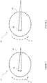
- Figures 1 and 2 illustrate a simple example of how an astigmatic eye 10 converges light passing through the lens.
- Figure 1 illustrates a horizontal meridian H of the eye 10. Light incident on the horizontal meridian passes through the crystalline lens 18 and converges behind the retina 14. The solid lines show that the light passing along the horizontal meridian H is focused at a location rearward of the retina 14 by a first amount.
- Figure 2 illustrates a vertical meridian V of the eye 10. In Figure 2 , solid lines illustrate that light passing along the vertical meridian V is focused at a location rearward of the retina 14 by a second amount greater than the first amount, which is the optical effect of astigmatism.
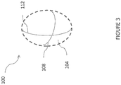
- FIG 3 shows a refractive element 100 that can correct for the rotational asymmetry of refractive power in an eye that causes astigmatism.
- the refractive element 100 includes a surface 104 that has a refractive power. That is, the surface 104 is configured to cause rays being refracted in an astigmatic eye and through the element 100 to converge at a common focal point.
- the surface 104 can have a refractive index that causes such convergence, can be curved to cause such convergence or can combine refractive index and curvature together or with other optical effects to cause such convergence.
- the surface 104 has a first curvature 108 and a second curvature 112. The first curvature 108 is less than the second curvature 112.
- the first curvature 108 has less optical power than the second curvature 112.
- the second curvature 112 induces more convergence of the rays that are incident on the surface 104 along a line of the second curvature 112 than the first curvature 108.
- the refractive element 100 can correct the astigmatism.
- the refractive element 100 can be placed in the eye 10 such that the first curvature 108 is aligned with the horizontal meridian H which is illustrated in Figure 1 .
- the first curvature 108 corrects the relatively smaller hyperopic error on the horizontal meridian H of the eye 10 by a first amount.
- the refractive element 100 can be placed in the eye 10 such that the second curvature 112 is aligned with the vertical meridian V which is illustrated in Figure 2 .
- Figure 3 shows the refractive element 100 surrounded by dashed lines.
- other components of an IOL incorporating the refractive element 100 can be coupled with the refractive element 100 either prior to implantation or during the course of the useful life of the IOL incorporating the refractive element 100.
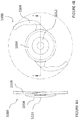
- an intraocular lens 1000 includes an optic 1004 and a mask 1012.
- the optic 1004 can be formed from an optically transmissive material, while the mask 1012 can be formed from an opaque material.
- the optic 1004 can include the refractive element 100 to correct refractive errors, such as rotationally asymmetric power, e.g., astigmatism.
- the optic 1004 can include other structures to improve the overall visual performance of the IOL 1000 in addition to the refractive element 100.
- the optic 1004 can be monofocal or multifocal and it can have positive or negative optical power.
- the optic 1004 may be aspheric or any other configuration as the context may dictate.
- the optic 1004 has a cylinder power or other rotationally asymmetric power such that the optic 1004 can correct for astigmatism of an eye as discussed above.
- the greatest thickness of the optic 1004 is at the center of the optic 1004.
- the optic 1004 may have a reduced thickness at its center, which is further described in U.S. Publication No. 2011/0040376, filed August 13, 2010 .
- the optic 1004 may be substantially circular with an outer diameter between about 5.0 mm and about 8.0 mm, such as about 6.0 mm.
- a central thickness of the optic 1004 can be less than or equal to about 1.0 mm, such as between about 0.75 mm and about 1.0 mm.
- the intraocular lens 1000 may include one or more haptics 1008 (e.g., one, two, three, four, or more) to prevent the intraocular lens 1000 from moving or rotating within the eye.
- haptics is intended to be a broad term encompassing struts and other mechanical structures that can be apposed against an inner surface of an eye and mounted to an optic to securely position an intraocular lens in an optical path of an eye.
- the haptics 1008 can be a variety of shapes and sizes depending on the location the intraocular lens 1000 is implanted in the eye.
- the haptics 1008 may be C-shaped, J-shaped, plate design, or any other design.
- the haptics 1008 may be manufactured substantially flat or vaulted with respect to the optic. Variations on the shape of the optic and the haptics can be found in U.S. Publication No. 2011/0040376, filed August 13, 2010 .
- the mask 1012 can be formed on an anterior surface 1016 of the optic 1004 (see Figures 4A-4D ), on a posterior surface 1020 of the optic 1004, or embedded within the optic 1004. When the mask 1012 is embedded within the optic 1004, the mask 1012 can be formed substantially at the midway line between the posterior 1020 and anterior surfaces 1016 of the optic 1004. But the mask 1012 can also be formed at other locations within the optic 1004. Additional information regarding the manufacturing of such intraocular lenses can be found in PCT Publication No. WO 2017/062316, filed October 3, 2016 .
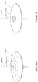
- Figure 5A illustrates a mask 2034a having an annular region 2036a surrounding an aperture 2038a substantially centrally located on the mask 2034a.
- An anterior surface of the annular region 2036a can have a curvature from the outer periphery to the inner periphery of the annular region 2036a, and the posterior surface of the annular region 2036a can have a similar curvature.
- Figure 5B shows that the mask 2034b can be flat in some implementations.
- the mask 2034b can include an annular region 2036b surrounding an aperture 2038b substantially centered on the optical axis 2039b of the mask 2034b.
- the outer periphery of the mask 2034a is generally circular with an outer diameter of at least about 3 mm and less than about 6 mm. In some implementations, the diameter of the outer periphery of the mask 2034a is at least about 3 mm and less than or equal to about 4 mm.
- a thickness of the mask 2034a can be constant or can vary between the inner periphery (near the aperture) and the outer periphery. For example, the thickness may increase from an outer periphery and/or inner periphery of the mask 2034a and toward a radial midline of the annular region 2036a.
- the thickness at any location of the mask 2034a can be less than or equal to about 200 microns, or less than or equal to about 100 microns, but preferably between about 1 micron and about 20 microns.
- the thickness of the mask 2034a can be within the range: from about 1 micron to about 40 microns, from about 5 microns to about 20 microns, from about 5 microns to about 15 microns.
- the thickness of the mask 2034a can be within about two microns of: about 15 microns, about 10 microns, about 8 microns, or about 5 microns.
- the aperture 2038a can transmit substantially all incident visible light along the optical axis 2039a.
- the aperture 2038a can be a through-hole in the annular region 2036a or a substantially light transmissive (e.g., transparent to visible light) portion thereof.
- the aperture 2038a can be substantially circular and/or substantially centered around the optical axis 2039a of the mask 2034a.
- the size of the aperture 2038a can be any size that is effective to increase the depth of focus of an eye of a patient with presbyopia.
- the size of the aperture 2038a can be dependent on die location of the mask 2034a within the eye (e.g., distance from the retina).
- the aperture 2038a can have a diameter of at least about 0.85 mm and less than or equal to about 2.8 mm, at least about 1.1 mm and less than or equal to about 1.6 mm, or at least about 1.3 mm and less than or equal to about 1.4 mm.
- the annular region 2036a can prevent transmission of substantially all or at least a portion of the spectrum of the incident visible light (e.g., radiant energy in the electromagnetic spectrum that is visible to the human eye) and/or the spectrum of non-visible light (e.g., radiant energy outside the range visible to humans). Preventing transmission of visible light through the annular region 2036a can block light that would not converge at the retina and fovea to form a sharp image.
- Figure 6 illustrates this effect.
- the TOL 1000 is placed in the capsular bag of the eye 10.
- the mask 1012 is centered on the optical axis of the eye 10. Rays that would not converge on the retina 14 are illustrated by the dash lines.
- the annular region 2036a can prevent transmission of at least about: 90 percent of incident visible light, 92 percent of incident visible light, 95 percent of incident visible light, 98 percent of all incident visible light, or 99 percent of all incident visible light.
- the annular region 2036a can transmit no more than about: 10 percent of incident visible light, 8 percent of incident visible light, 5 percent of incident visible light, 3 percent of incident visible light, 2 percent of incident visible light, or 1 percent of incident visible light.
- opacity of the annular region 2036a is achieved because the material used to make mask 2034a is naturally opaque.
- the material used to make the mask 2034a may be naturally substantially clear but treated with a dye or other pigmentation agent (e.g., carbon black).
- the mask is made of the same material as the lens body, with the addition of dye or other pigmentation agent. In other implementations, the mask is made of a different material from the lens body.
- Figure 7 is a Zemax optical simulation of the optical performance of a 21 diopter monofocal IOL.
- corneal aberration is corrected and the simulation assumes a realistic polychromatic model eye, with a 3 mm pupil.
- the left-most box shows the visual acuity for 0 diopter defocus.
- the acuity illustrated is acceptable at 20/20 or greater.
- the second box from the left shows the visual acuity for a -0.5 diopter defocus using the same lens and model used in the leftmost box.
- the threshold acuity level is still at about 20/20.
- the third box from the left shows the visual acuity for a -1.0 diopter defocus using the same lens and simulation model used in generating the left-most box.
- This box does not register any level of visual acuity and thus the IOL is completely ineffective at this and greater defocus amounts.
- Figure 7 lower row, is a Zemax optical simulation of the optical performance of an IOL that has a small aperture mask disposed therein for extended depth of focus.
- the small aperture optic can have a 1.36 mm working aperture.
- the IOL had optimal focus.
- the simulation used a realistic polychromatic model eye with a 3 mm pupil.
- the left-most box shows the visual acuity for 0 diopter defocus, which is acceptable at 20/20 or greater.
- each of the defocus positions m the lower row from the left most box toward the right from -0.5 diopter, -1.0 diopter, -1.5 diopter and -2.0 diopter defocus show a 20/20 visual acuity or better.
- This simulation confirms the effectiveness of the small aperture optic illustrated in Figure 6 .
- Figure 8 is a Zemax optical simulation of the optical performance of a 21 diopter monofocal IOL correcting corneal aberration using a realistic polychromatic model eye, with a 3 mm pupil.
- the left-most box shows the visual acuity for 0 diopter added cylinder power. The acuity illustrated is acceptable at 20/20 or greater.
- the third box from the left shows the visual acuity for a -0.5 diopter addition of cylinder power using the same lens and model used in the left-most box.
- the threshold acuity level is still at about 20/20.
- the fifth box from the left shows the visual acuity for a -1.0 diopter addition of cylinder power using the same lens and model used in the left-most box.
- This box does not register any useful level of visual acuity and thus the IOL is completely-ineffective at this and greater amounts of cylinder.
- Figure 8 lower row, is a Zemax optical simulation of an I0L with a small aperture mask that provides extended depth of focus.
- the mask was provided with a 1.36 working aperture and the IOL with optimal focus.
- the model again was constructed using a realistic polychromatic model eye with a 3 nm pupil.
- the left-most box shows the visual acuity for 0 added cylinder power and in this box the acuity illustrated is acceptable at 20/20 or greater.
- the third and fifth boxes from the left show the visual acuity for a -0.5 and -1.0 diopter added cylinder power using the same lens and model used in the left-most box, lower row.
- the threshold acuity level is still at about 20/20.
- Figure 9 shows the performance of a toric IOL.
- Figure 9 upper row, is a Zemax optical simulation of the optical performance of a 3 diopter toric monofocal IOL using a realistic polychromatic model eye, with a 3 mm pupil and with a toric cornea.
- the performance of the toric IOL is similar to that of the monofocal IOL illustrated in Figure 7 . That is, it can tolerate about -0.5 diopter defocus. But greater amounts of defocus degrade the visual acuity too much for the toric IOL to provide functional visual acuity.
- Figure 9 shows that astigmatism in an eye can be more robustly corrected by a 3 diopter toric IOL with a small aperture optic, e.g., having a 1.36 mm working aperture with the IOL having optimal focus.
- the lower row shows that the toric IOL with small aperture optic can still perform well at up to -2.0 diopters of defocus.
- Figure 10 shows a further comparison of the performance of a 21 diopter monofocal toric IOL and the same IOL with a small aperture optic, e.g., an optic having a 1.36 mm working aperture.
- Figure 10 shows the ability of these two IOLs to sustain visual acuity when working with progressively more additional cylinder power.
- the upper row shows that a toric IOL can sustain acceptable visual acuity up to an additional -0.5 diopter of cylinder.
- the lower row shows that the toric IOL with a small aperture optic can perform well even when subject to up to -1.5 diopter of cylinder. This means that even in a patient with progressively worsening astigmatism, the toric IOL with small aperture optic can continue to provide good vision without additional lenses or procedures for much longer than the standard toric IOL.
- Figure 11 shows a further comparison of the performance of a 21 diopter monofocal toric IOL and the same IOL with a small aperture optic, e.g., an optic having a 1.36 mm working aperture.
- Figure 11 shows the ability of these two IOLs to sustain rotational misplacement.
- the upper row shows that a toric IOL can sustain a 5 degree rotational misplacement or misalignment. Beyond this amount, the visual acuity delivered by the standard toric IOL is insufficient.
- the lower row shows that the toric IOL with a small aperture optic can perform well at up to 15 degrees of rotational misplacement or misalignment. This means that even where an IOL implantation procedure was not according to a pre-operative plan, the IOL will perform well.
- the simulation performance can be summarized as follows: IOL Configuration Performance Measurement Standard Monofocal IOL Standard Monofocal Toric IOL EDOF Small Aperture IOL EDOF Small Aperture Toric IOL Tolerance to Astigmatism ⁇ 0.5 D ⁇ 0.5 D ⁇ 1.5 D ⁇ 1.5 D Tolerance to Angular Rotational Placement N/A ⁇ 5° N/A ⁇ 15° Depth of Focus ⁇ 0.5 D ⁇ 0.5 D ⁇ 2.0 D ⁇ 2.0 D
- Figure 12 schematically illustrates aspects of certain implementations.
- a cylinder power exists in the eye 10 prior to correction causing astigmatism.
- the power in the vertical meridian V is noticeably less than in the horizontal meridian H.
- the IOL 1000 including the refractive element 100 is provided and is placed in the eye 10.
- the refractive element 100 has different powers in different portions.
- a meridian of the refractive element 100 can have the first curvature 108 and another meridian of the element 100 can have the second curvature 112 larger than the first curvature.
- the curvatures 108, 112 are along perpendicular meridians, but could be at other angles to each other as a function of the power profile of the eye.
- the second curvature 112 should optimally be aligned with the vertical meridian V of the eye 10 so that the locally lower power of the eye 10 is compensated by the second curvature 112 to enable the vertical and horizontal meridians V, H to converge at the same location.
- the refractive element 100 is rotationally offset from the optimal aligned position.
- the IOL 1000 is enabled by the combination of a toric configuration of the refractive element 100 and the mask 1012 to have a much larger than conventional acceptable rotational offset from the optimal position.
- Figure 12 shows in the shaded pie-shaped region that there is an acceptable acuity over a large IOL placement range.
- the range extends on both sides, e.g., symmetrically, of the optimal (vertical) position.
- IOL 1000 provides an increase in tolerance to rotational misplacement.
- the range extends beyond the angle of misplacement of the IOL 1000.
- the range would be much less, for example between the position of the second curvature 112 and the vertical meridian V preventing the conventional IOL when placed as shown in Figure 12 from providing functional visual acuity.
- Conditional language such as “can,” “could,” “might,” or “may,” unless specifically stated otherwise, or otherwise understood within the context as used, is generally intended to convey that certain examples include, while other examples do not include, certain features, elements, and/or steps. Thus, such conditional language is not generally intended to imply that features, elements, and/or steps are in any way required for one or more examples or that one or more examples necessarily include logic for deciding, with or without user input or prompting, whether these features, elements, and/or steps are included or are to be performed in any particular example.
Description
- This application is directed to ophthalmic devices that can be used to improve vision in patients suffering from astigmatism.
- The human eye functions to provide vision by transmitting and focusing light through the cornea and through the crystalline lens in the eye to form a focused image on a retina. The quality of the focused image depends on many factors including the size and shape of the eye, the transparency of the cornea and the lens, as well as the capability of the lens to accommodate.
- The optical power of the eye is a function of the optical power of the cornea and the crystalline lens. In a normal, healthy eye, sharp images of distant objects are formed on the retina. This vision state is called emmetropia. In myopic eyes, images of distant objects are formed at a location in front of the retina. This may be because the eye is abnormally long or the cornea is abnormally steep. In hyperopic eyes, images are formed at a location behind the retina. This may be because the eye is abnormally short or the cornea is abnormally flat. The focusing effect of the eye may be rotationally asymmetric, resulting in an uncompensated cylindrical refractive error referred to as astigmatism.
- Some people suffer from cataracts in which the crystalline lens undergoes a loss of transparency. In such cases, the crystalline lens can be removed and replaced with an intraocular lens (IOL). However, commercially approved intraocular lenses do not restore full vision function and even small misplacement in the eye can result in sub-optimal vision correction. As a result, many patients are subject to inconvenient post-operative strategies to cope.
- In
US 4,795,462 there is described an implantable or contact lens for replacement of a defective natural lens in an eye in which various annular portions of the lens have different powers and focal lengths to produce in-focus images, on different portions of the retina, of objects which are located at various distances from the eye, thereby substituting for the natural focusing action of the eye. The image processing capability of the brain functions to largely ignore the out of focus images and concentrate on the in focus image of the object selected by the brain for consideration. - In
US 2011/0040376 there are described Intraocular implants and methods of making intraocular implants. The intraocular implants can improve the vision of a patient, such as by increasing the depth of focus of an eye of a patient. In particular, the intraocular implants can include a mask having an annular portion with a relatively low visible light transmission surrounding a relatively high transmission central portion such as a clear lens or aperture. This construct is adapted to provide an annular mask with a small aperture for light to pass through to the retina to increase depth of focus. The intraocular implant may have an optical power for refractive correction. The intraocular implant may be implanted in any location along the optical pathway in the eye, e.g., as an implant in the anterior or posterior chamber. - In
US 2011/0166652 there is described a method, system and apparatus for vision correction. The method, system and apparatus include a toric intraocular element for correcting astigmatism and having a cylinder power, and a depth of focus extender coupled to the toric intraocular element, the depth of focus extender extending a depth of focus. The extended depth of focus may reduce sensitivity of the toric intraocular element to at least one of rotation and selected cylinder power. - This application is directed to providing a better outcome for patients undergoing intraocular refractive vision correction. This application discloses devices that can simplify treatment of complex cases, such as patients who have a lack of accommodation, cataract, and/or astigmatism,
- According to the present invention there is provided an intraocular lens having the features of claim 1. Further aspects and preferred embodiments are defined in the appended claims. Aspects, embodiments and examples of the present disclosure which do not fall under the scope of the appended claims do not form part of the invention and are merely provided for illustrative purposes. Furthermore, the methods presented in the present description are provided for illustrative purposes only and do not form part of the present invention.
- An intraocular lens is provided comprising an optic that includes a refractive element. The refractive element has a first power in a first meridian and a second power greater than the first power in a second meridian. A magnitude of the first and second powers and a location of the first and second meridians are configured to correct astigmatism in a human eye.
- The intraocular lens also comprises a mask having an annular region surrounding an aperture substantially centrally located on the mask. The mask is configured to prevent light from passing through the annular region and to permit light to pass through the central aperture to increase depth of focus and to increase tolerance to rotational misplacement within the eye by as much as 15 degrees.
- Various examples are depicted in the accompanying drawings for illustrative purposes, and should in no way be interpreted as limiting the scope of the invention. Furthermore, various features of different disclosed examples can be combined to form additional examples, which are part of this disclosure.
-
Figure 1 schematically illustrates uncorrected and corrected focusing effect along a horizontal meridian of an eye with astigmatism in which the lowest power meridian of the eye is aligned with the horizontal meridian. -
Figure 2 schematically illustrates uncorrected and corrected focusing effect along a vertical meridian of an eye with astigmatism in which the highest power meridian of the eye is aligned with the vertical meridian. -
Figure 3 illustrates a power distribution of a refractive element of an intraocular lens (IOL) configured to correct for the rotationally asymmetric refractive error illustrated inFigures 1 and 2 . -
Figures 4A-4D illustrate an example of an IOL having a refractive element and a mask coupled with the refractive element. -
Figure 5A illustrates an example of a mask. -
Figure 5B illustrates another example of the mask. -
Figure 6 schematically illustrates the depth of focus extending effect of the masks ofFigures 5A and 5B . -
Figure 7 shows simulated defocus performance of a monofocal IOL with corneal aberration correction compared with the same IOL additionally incorporating a small aperture optic. -
Figure 8 shows simulated cylinder performance of a monofocal IOL with corneal aberration correction compared with the same IOL additionally incorporating a small aperture optic. -
Figure 9 shows simulated defocus performance of a monofocal toric IOL in an eye system with cylinder cornea compared with the same IOL additionally incorporating a small aperture optic. -
Figure 10 shows simulated cylinder performance of a monofocal toric IOL in an eye system with cylinder at the cornea and additional cylinder at the IOL plane compared with the same IOL additionally incorporating a small aperture optic. -
Figure 11 shows simulated rotational misalignment performance of a monofocal toric IOL in an eye system with cylinder at the cornea compared with the same IOL additionally incorporating a small aperture optic. -
Figure 12 is a schematic diagram of an eye showing increased tolerance to misplacement as provided by certain implementations herein. - A patient with astigmatism has unequal optical power at different rotational positions of the eye. The power of the eye is greater in some meridians of the eye than in other meridians. Patients who undergo IOL implantation surgery may suffer from astigmatism. This may be because even if the IOL has perfectly symmetric optics, the cornea of the eye in which the IOL is placed may be formed in a way providing uneven, rotationally asymmetric powers.
-
Figures 1 and 2 illustrate a simple example of how anastigmatic eye 10 converges light passing through the lens.Figure 1 illustrates a horizontal meridian H of theeye 10. Light incident on the horizontal meridian passes through thecrystalline lens 18 and converges behind theretina 14. The solid lines show that the light passing along the horizontal meridian H is focused at a location rearward of theretina 14 by a first amount.Figure 2 illustrates a vertical meridian V of theeye 10. InFigure 2 , solid lines illustrate that light passing along the vertical meridian V is focused at a location rearward of theretina 14 by a second amount greater than the first amount, which is the optical effect of astigmatism. -
Figure 3 shows arefractive element 100 that can correct for the rotational asymmetry of refractive power in an eye that causes astigmatism. Therefractive element 100 includes asurface 104 that has a refractive power. That is, thesurface 104 is configured to cause rays being refracted in an astigmatic eye and through theelement 100 to converge at a common focal point. Thesurface 104 can have a refractive index that causes such convergence, can be curved to cause such convergence or can combine refractive index and curvature together or with other optical effects to cause such convergence. In one example, thesurface 104 has afirst curvature 108 and asecond curvature 112. Thefirst curvature 108 is less than thesecond curvature 112. As a result, thefirst curvature 108 has less optical power than thesecond curvature 112. Thesecond curvature 112 induces more convergence of the rays that are incident on thesurface 104 along a line of thesecond curvature 112 than thefirst curvature 108. - If the
refractive element 100 is properly placed in theastigmatic eye 10 illustrated inFigures 1 and 2 , therefractive element 100 can correct the astigmatism. Therefractive element 100 can be placed in theeye 10 such that thefirst curvature 108 is aligned with the horizontal meridian H which is illustrated inFigure 1 . When so placed, thefirst curvature 108 corrects the relatively smaller hyperopic error on the horizontal meridian H of theeye 10 by a first amount. Therefractive element 100 can be placed in theeye 10 such that thesecond curvature 112 is aligned with the vertical meridian V which is illustrated inFigure 2 . When placed such that thesecond curvature 112 is aligned with the vertical meridian, the relatively larger hyperopic error is corrected by a larger amount than was corrected in the horizontal meridian H. As a result, the rays on both meridians are brought into focus at the same location. An additional power can be provided if needed to shift the focal plane to the retina as illustrated by the solid converging lines inFigures 1 and 2 . -
Figure 3 shows therefractive element 100 surrounded by dashed lines. As discussed further below, other components of an IOL incorporating therefractive element 100 can be coupled with therefractive element 100 either prior to implantation or during the course of the useful life of the IOL incorporating therefractive element 100. - As shown in
Figures 4A-4D , anintraocular lens 1000 includes an optic 1004 and amask 1012. The optic 1004 can be formed from an optically transmissive material, while themask 1012 can be formed from an opaque material. The optic 1004 can include therefractive element 100 to correct refractive errors, such as rotationally asymmetric power, e.g., astigmatism. The optic 1004 can include other structures to improve the overall visual performance of theIOL 1000 in addition to therefractive element 100. - The optic 1004 can be monofocal or multifocal and it can have positive or negative optical power. The optic 1004 may be aspheric or any other configuration as the context may dictate. In various implementations the optic 1004 has a cylinder power or other rotationally asymmetric power such that the optic 1004 can correct for astigmatism of an eye as discussed above. In some implementations, the greatest thickness of the optic 1004 is at the center of the
optic 1004. In other implementations, the optic 1004 may have a reduced thickness at its center, which is further described inU.S. Publication No. 2011/0040376, filed August 13, 2010 . The optic 1004 may be substantially circular with an outer diameter between about 5.0 mm and about 8.0 mm, such as about 6.0 mm. A central thickness of the optic 1004 can be less than or equal to about 1.0 mm, such as between about 0.75 mm and about 1.0 mm. - The
intraocular lens 1000 may include one or more haptics 1008 (e.g., one, two, three, four, or more) to prevent theintraocular lens 1000 from moving or rotating within the eye. As used herein the term "haptic" is intended to be a broad term encompassing struts and other mechanical structures that can be apposed against an inner surface of an eye and mounted to an optic to securely position an intraocular lens in an optical path of an eye. Thehaptics 1008 can be a variety of shapes and sizes depending on the location theintraocular lens 1000 is implanted in the eye. Thehaptics 1008 may be C-shaped, J-shaped, plate design, or any other design. Thehaptics 1008 may be manufactured substantially flat or vaulted with respect to the optic. Variations on the shape of the optic and the haptics can be found inU.S. Publication No. 2011/0040376, filed August 13, 2010 . - The
mask 1012 can be formed on ananterior surface 1016 of the optic 1004 (seeFigures 4A-4D ), on aposterior surface 1020 of the optic 1004, or embedded within theoptic 1004. When themask 1012 is embedded within theoptic 1004, themask 1012 can be formed substantially at the midway line between the posterior 1020 andanterior surfaces 1016 of theoptic 1004. But themask 1012 can also be formed at other locations within theoptic 1004. Additional information regarding the manufacturing of such intraocular lenses can be found inPCT Publication No. WO 2017/062316, filed October 3, 2016 . Mask -
Figure 5A illustrates a mask 2034a having an annular region 2036a surrounding an aperture 2038a substantially centrally located on the mask 2034a. An anterior surface of the annular region 2036a can have a curvature from the outer periphery to the inner periphery of the annular region 2036a, and the posterior surface of the annular region 2036a can have a similar curvature.Figure 5B shows that the mask 2034b can be flat in some implementations. The mask 2034b can include an annular region 2036b surrounding an aperture 2038b substantially centered on the optical axis 2039b of the mask 2034b. Although the features described below are described with respect to the mask 2034a, one or the more of the features may be applied to the mask 2034b. - In some implementations, the outer periphery of the mask 2034a is generally circular with an outer diameter of at least about 3 mm and less than about 6 mm. In some implementations, the diameter of the outer periphery of the mask 2034a is at least about 3 mm and less than or equal to about 4 mm.
- A thickness of the mask 2034a can be constant or can vary between the inner periphery (near the aperture) and the outer periphery. For example, the thickness may increase from an outer periphery and/or inner periphery of the mask 2034a and toward a radial midline of the annular region 2036a. In general, the thickness at any location of the mask 2034a can be less than or equal to about 200 microns, or less than or equal to about 100 microns, but preferably between about 1 micron and about 20 microns. For example, the thickness of the mask 2034a can be within the range: from about 1 micron to about 40 microns, from about 5 microns to about 20 microns, from about 5 microns to about 15 microns. In some implementations, the thickness of the mask 2034a can be within about two microns of: about 15 microns, about 10 microns, about 8 microns, or about 5 microns.
- The aperture 2038a can transmit substantially all incident visible light along the optical axis 2039a. For example, the aperture 2038a can be a through-hole in the annular region 2036a or a substantially light transmissive (e.g., transparent to visible light) portion thereof. The aperture 2038a can be substantially circular and/or substantially centered around the optical axis 2039a of the mask 2034a. The size of the aperture 2038a can be any size that is effective to increase the depth of focus of an eye of a patient with presbyopia. In particular, the size of the aperture 2038a can be dependent on die location of the mask 2034a within the eye (e.g., distance from the retina). In some implementations, the aperture 2038a can have a diameter of at least about 0.85 mm and less than or equal to about 2.8 mm, at least about 1.1 mm and less than or equal to about 1.6 mm, or at least about 1.3 mm and less than or equal to about 1.4 mm.
- The annular region 2036a can prevent transmission of substantially all or at least a portion of the spectrum of the incident visible light (e.g., radiant energy in the electromagnetic spectrum that is visible to the human eye) and/or the spectrum of non-visible light (e.g., radiant energy outside the range visible to humans). Preventing transmission of visible light through the annular region 2036a can block light that would not converge at the retina and fovea to form a sharp image.
Figure 6 illustrates this effect. In particular, theTOL 1000 is placed in the capsular bag of theeye 10. Themask 1012 is centered on the optical axis of theeye 10. Rays that would not converge on theretina 14 are illustrated by the dash lines. These rays are blocked by the annular region 2036a or the annular region 2036b of themask 1012 and thus are prevented from degrading vision by causing a blur on the retina. Rays that converge on theretina 14 pass through the aperture of themask 1012. A crisp image over a range of distances is provided by this focused light as discussed further below. - In some implementations, the annular region 2036a can prevent transmission of at least about: 90 percent of incident visible light, 92 percent of incident visible light, 95 percent of incident visible light, 98 percent of all incident visible light, or 99 percent of all incident visible light. The annular region 2036a can transmit no more than about: 10 percent of incident visible light, 8 percent of incident visible light, 5 percent of incident visible light, 3 percent of incident visible light, 2 percent of incident visible light, or 1 percent of incident visible light.
- In some implementations, opacity of the annular region 2036a is achieved because the material used to make mask 2034a is naturally opaque. In other implementations, the material used to make the mask 2034a may be naturally substantially clear but treated with a dye or other pigmentation agent (e.g., carbon black). In some implementations, the mask is made of the same material as the lens body, with the addition of dye or other pigmentation agent. In other implementations, the mask is made of a different material from the lens body.
- Further variations of masks can be found in
U.S. Application No. 62/237429, filed October 5, 2015 U.S. Patent No. 7,628,810, filed May 26, 2004 ,U.S. Publication No. 2012/0143325, filed February 19, 2012 ,U.S. Publication No. 2011/0040376, filed August 13, 2010 ;U.S. Publication No. 2013/0268071, filed November 30, 2012 ;U.S. Publication No. 2014/0264981 ;U.S. Publication No. 2015/0073549, filed August 7, 2014 ;U.S. Patent No. 5,662,706, filed June 14, 1996 ;U.S. Patent No. 5,905,561, filed June 14, 1996 ; andU.S. Patent No. 5,965,330, filed December 6, 1996 . -
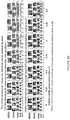
Figure 7 , upper row, is a Zemax optical simulation of the optical performance of a 21 diopter monofocal IOL. In the Simulation, corneal aberration is corrected and the simulation assumes a realistic polychromatic model eye, with a 3 mm pupil. The left-most box shows the visual acuity for 0 diopter defocus. The acuity illustrated is acceptable at 20/20 or greater. The second box from the left shows the visual acuity for a -0.5 diopter defocus using the same lens and model used in the leftmost box. One can see that the performance has declined, but the threshold acuity level is still at about 20/20. The third box from the left shows the visual acuity for a -1.0 diopter defocus using the same lens and simulation model used in generating the left-most box. One can see that this box does not register any level of visual acuity and thus the IOL is completely ineffective at this and greater defocus amounts. -
Figure 7 , lower row, is a Zemax optical simulation of the optical performance of an IOL that has a small aperture mask disposed therein for extended depth of focus. The small aperture optic can have a 1.36 mm working aperture. The IOL had optimal focus. The simulation used a realistic polychromatic model eye with a 3 mm pupil. The left-most box shows the visual acuity for 0 diopter defocus, which is acceptable at 20/20 or greater. In contrast to the upper row, each of the defocus positions m the lower row from the left most box toward the right from -0.5 diopter, -1.0 diopter, -1.5 diopter and -2.0 diopter defocus show a 20/20 visual acuity or better. This simulation confirms the effectiveness of the small aperture optic illustrated inFigure 6 . -
Figure 8 , upper row, is a Zemax optical simulation of the optical performance of a 21 diopter monofocal IOL correcting corneal aberration using a realistic polychromatic model eye, with a 3 mm pupil. The left-most box shows the visual acuity for 0 diopter added cylinder power. The acuity illustrated is acceptable at 20/20 or greater. The third box from the left shows the visual acuity for a -0.5 diopter addition of cylinder power using the same lens and model used in the left-most box. One can see that the performance has declined, but the threshold acuity level is still at about 20/20. The fifth box from the left shows the visual acuity for a -1.0 diopter addition of cylinder power using the same lens and model used in the left-most box. One can see that this box does not register any useful level of visual acuity and thus the IOL is completely-ineffective at this and greater amounts of cylinder. -
Figure 8 , lower row, is a Zemax optical simulation of an I0L with a small aperture mask that provides extended depth of focus. The mask was provided with a 1.36 working aperture and the IOL with optimal focus. The model again was constructed using a realistic polychromatic model eye with a 3 nm pupil. The left-most box shows the visual acuity for 0 added cylinder power and in this box the acuity illustrated is acceptable at 20/20 or greater. The third and fifth boxes from the left show the visual acuity for a -0.5 and -1.0 diopter added cylinder power using the same lens and model used in the left-most box, lower row. One can see that the performance has declined, but the threshold acuity level is still at about 20/20. In fact the performance of the small aperture IOL remains acceptable even to the right-most box which illustrates performance with -1.5 diopter of cylinder.Figure 8 thus shows that a small aperture IOL can provide vision correction for small amounts of astigmatism even up to -1.5 diopters of added cylinder. -
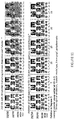
Figure 9 shows the performance of a toric IOL. In particular,Figure 9 , upper row, is a Zemax optical simulation of the optical performance of a 3 diopter toric monofocal IOL using a realistic polychromatic model eye, with a 3 mm pupil and with a toric cornea. The performance of the toric IOL is similar to that of the monofocal IOL illustrated inFigure 7 . That is, it can tolerate about -0.5 diopter defocus. But greater amounts of defocus degrade the visual acuity too much for the toric IOL to provide functional visual acuity. In contrast,Figure 9 , lower row, shows that astigmatism in an eye can be more robustly corrected by a 3 diopter toric IOL with a small aperture optic, e.g., having a 1.36 mm working aperture with the IOL having optimal focus. The lower row shows that the toric IOL with small aperture optic can still perform well at up to -2.0 diopters of defocus. -
Figure 10 shows a further comparison of the performance of a 21 diopter monofocal toric IOL and the same IOL with a small aperture optic, e.g., an optic having a 1.36 mm working aperture.Figure 10 shows the ability of these two IOLs to sustain visual acuity when working with progressively more additional cylinder power. The upper row shows that a toric IOL can sustain acceptable visual acuity up to an additional -0.5 diopter of cylinder. The lower row shows that the toric IOL with a small aperture optic can perform well even when subject to up to -1.5 diopter of cylinder. This means that even in a patient with progressively worsening astigmatism, the toric IOL with small aperture optic can continue to provide good vision without additional lenses or procedures for much longer than the standard toric IOL. -
Figure 11 shows a further comparison of the performance of a 21 diopter monofocal toric IOL and the same IOL with a small aperture optic, e.g., an optic having a 1.36 mm working aperture.Figure 11 shows the ability of these two IOLs to sustain rotational misplacement. The upper row shows that a toric IOL can sustain a 5 degree rotational misplacement or misalignment. Beyond this amount, the visual acuity delivered by the standard toric IOL is insufficient. The lower row shows that the toric IOL with a small aperture optic can perform well at up to 15 degrees of rotational misplacement or misalignment. This means that even where an IOL implantation procedure was not according to a pre-operative plan, the IOL will perform well. This is because the IOL has a much wider window of acceptable rotational placement. The lower row ofFigure 11 suggests that a 30 degree window can be provided within which a patient will have acceptable visual acuity. This is three times larger than the much more limited range of placement that a standard IOL can tolerate. This represents a significant improvement in toric IOL design, enhancing the robustness of the IOL such that the chance of a poor outcome even if placement is sub-optimal is greatly reduced. - The simulation performance can be summarized as follows:
IOL Configuration Performance Measurement Standard Monofocal IOL Standard Monofocal Toric IOL EDOF Small Aperture IOL EDOF Small Aperture Toric IOL Tolerance to Astigmatism ≤ 0.5 D ≤ 0.5 D ≤ 1.5 D ±≤ 1.5 D Tolerance to Angular Rotational Placement N/A ±≤ 5° N/A ±≤ 15° Depth of Focus ±≤ 0.5 D ±≤ 0.5 D ±≤2.0 D ±≤2.0 D -
Figure 12 schematically illustrates aspects of certain implementations. In particular, a cylinder power exists in theeye 10 prior to correction causing astigmatism. In this case, the power in the vertical meridian V is noticeably less than in the horizontal meridian H. TheIOL 1000 including therefractive element 100 is provided and is placed in theeye 10. As discussed above, therefractive element 100 has different powers in different portions. For example, a meridian of therefractive element 100 can have thefirst curvature 108 and another meridian of theelement 100 can have thesecond curvature 112 larger than the first curvature. Thecurvatures second curvature 112 induces more convergence. Accordingly, thesecond curvature 112 should optimally be aligned with the vertical meridian V of theeye 10 so that the locally lower power of theeye 10 is compensated by thesecond curvature 112 to enable the vertical and horizontal meridians V, H to converge at the same location. However, as shown, therefractive element 100 is rotationally offset from the optimal aligned position. Advantageously, theIOL 1000 is enabled by the combination of a toric configuration of therefractive element 100 and themask 1012 to have a much larger than conventional acceptable rotational offset from the optimal position.Figure 12 shows in the shaded pie-shaped region that there is an acceptable acuity over a large IOL placement range. In this example, the range extends on both sides, e.g., symmetrically, of the optimal (vertical) position. Assuch IOL 1000 provides an increase in tolerance to rotational misplacement. The range extends beyond the angle of misplacement of theIOL 1000. In the conventional IOL, the range would be much less, for example between the position of thesecond curvature 112 and the vertical meridian V preventing the conventional IOL when placed as shown inFigure 12 from providing functional visual acuity. - Conditional language, such as "can," "could," "might," or "may," unless specifically stated otherwise, or otherwise understood within the context as used, is generally intended to convey that certain examples include, while other examples do not include, certain features, elements, and/or steps. Thus, such conditional language is not generally intended to imply that features, elements, and/or steps are in any way required for one or more examples or that one or more examples necessarily include logic for deciding, with or without user input or prompting, whether these features, elements, and/or steps are included or are to be performed in any particular example.
- The terms "comprising," "including," "having," and the like are synonymous and are used inclusively, in an open-ended fashion, and do not exclude additional elements, features, acts, operations, and so forth. Also, the term "or" is used in its inclusive sense (and not in its exclusive sense) so that when used, for example, to connect a list of elements, the term "or" means one, some, or all of the elements in the list.
- The terms "approximately," "about," and "substantially" as used herein represent an amount close to the stated amount that still performs a desired function or achieves a desired result. For example, the terms "approximately," "about," and "substantially" may refer to an amount that is within less than 10% of the stated amount, as the context may dictate.
- The ranges disclosed herein also encompass any and all overlap, subranges, and combinations thereof. Language such as "up to," "at least," "greater than," "less than," "between" and the like includes the number recited. Numbers preceded by a term such as "about" or "approximately" include the recited numbers. For example, "about 3 mm" includes "3 mm."
- Although certain implementations and examples have been described herein, it will be understood by those skilled in the art that many aspects of the IOLs shown and described in the present disclosure may be differently combined and/or modified to form still further implementations or acceptable examples. All such modifications and variations are intended to be included herein within the scope of this disclosure. A wide variety of designs and approaches are possible. For purposes of this disclosure, certain aspects, advantages, and novel features are described herein. It is to be understood that not necessarily all such advantages may be achieved in accordance with any particular implementation. Thus, for example, those skilled in the art will recognize that the disclosure may be embodied or carried out in a manner that achieves one advantage or a group of advantages as taught herein without necessarily achieving other advantages as may be taught or suggested herein.
- Moreover, while illustrative examples have been described herein, the scope of any and all examples having equivalent elements, modifications, omissions, combinations (e.g., of aspects across various examples), adaptations and/or alterations as would be appreciated by those skilled in the art based on the present disclosure. The limitations in the claims are to be interpreted broadly based on the language employed in the claims and not limited to the examples described in the present specification or during the prosecution of the application, which examples are to be construed as non-exclusive. It is intended, therefore, that the specification and examples be considered as illustrative only, with a true scope being indicated by the claims.
Claims (14)
- An intraocular lens (1000) comprising:an optic (1004) including a refractive element (100), the refractive element (100) comprising a first power in a first meridian and a second power greater than the first power in a second meridian, a magnitude of the first and second powers and a location of the first and second meridians being configured to correct astigmatism in a human eye; anda mask (1012) having an annular region (2036a) surrounding an aperture (2038a) substantially centrally located on the mask (1012), the mask (1012) being configured to prevent light from passing through the annular region (2036a) and to permit light to pass through the central aperture (2038a) to increase depth of focus and to increase tolerance to rotational misplacement within the eye by as much as +/- 15 degrees.
- The intraocular lens (1000) of Claim 1, wherein the refractive element (100) comprises a toric configuration.
- The intraocular lens (1000) of Claim 1 or Claim 2, wherein the mask (1012) is configured to increase depth of focus by a magnitude equivalent to up to 2 diopters of add power.
- The intraocular lens (1000) of any one of the preceding claims, wherein the intraocular lens (1000) is monofocal.
- The intraocular lens (1000) of any one of claims 1 to 4, wherein the mask (1012) is coupled with an anterior face (1016) of the optic (1004) incorporating the mask (1012).
- The intraocular lens (1000) of claim 5 wherein the mask (1012) is formed on a piggyback IOL configured to couple with the eye to place the mask (1012) on the anterior face (1016) of the optic (1004).
- The intraocular lens (1000) of any one of claims 1 to 4, wherein the mask (1012) is embedded in the optic (1004) comprising the refractive element (100).
- The intraocular lens (1000) of any one of the preceding claims, wherein the aperture (2038a) has a diameter of less than about 2.8 mm.
- The intraocular lens (1000) of any one of the preceding claims, wherein the mask (1012) is configured to fracture in predictable manner upon placement in the eye through a small bore IOL inserter.
- The intraocular lens (1000) of any one of the preceding claims, wherein the mask (1012) comprises a plurality of small holes disposed through the annular region (2036a) to secure the mask (1012) to the optic (1004) including the refractive element (100).
- The intraocular lens (1000) of any one of the preceding claims, wherein the mask (1012) is generally circular.
- The intraocular lens (1000) of any one of the preceding claims, wherein the intraocular lens (1000) is configured to maintain the same visual acuity level from 0.0 to +/-1.5 diopters of cylinder.
- The intraocular lens (1000) of any one of the preceding claims, wherein the intraocular lens (1000) is configured to maintain the same visual acuity level from 0.0 to - 2.0 diopters of defocus.
- The intraocular lens (1000) of any one of the preceding claims, wherein the mask (1012) is configured to increase depth of focus by a magnitude equivalent to up to 2 diopters of add power.
Applications Claiming Priority (2)
| Application Number | Priority Date | Filing Date | Title |
|---|---|---|---|
| US201562259524P | 2015-11-24 | 2015-11-24 | |
| PCT/US2016/063181 WO2017091520A1 (en) | 2015-11-24 | 2016-11-21 | Toric small aperture intraocular lens with extended depth of focus |
Publications (3)
| Publication Number | Publication Date |
|---|---|
| EP3384342A1 EP3384342A1 (en) | 2018-10-10 |
| EP3384342A4 EP3384342A4 (en) | 2019-08-14 |
| EP3384342B1 true EP3384342B1 (en) | 2021-08-25 |
Family
ID=58763587
Family Applications (1)
| Application Number | Title | Priority Date | Filing Date |
|---|---|---|---|
| EP16869140.0A Active EP3384342B1 (en) | 2015-11-24 | 2016-11-21 | Toric small aperture intraocular lens with extended depth of focus |
Country Status (7)
| Country | Link |
|---|---|
| US (2) | US11464625B2 (en) |
| EP (1) | EP3384342B1 (en) |
| JP (1) | JP7055747B2 (en) |
| KR (1) | KR102407311B1 (en) |
| CN (1) | CN108431676B (en) |
| CA (1) | CA3005891C (en) |
| WO (1) | WO2017091520A1 (en) |
Families Citing this family (13)
| Publication number | Priority date | Publication date | Assignee | Title |
|---|---|---|---|---|
| US7628810B2 (en) | 2003-05-28 | 2009-12-08 | Acufocus, Inc. | Mask configured to maintain nutrient transport without producing visible diffraction patterns |
| US9492272B2 (en) | 2009-08-13 | 2016-11-15 | Acufocus, Inc. | Masked intraocular implants and lenses |
| US10004593B2 (en) | 2009-08-13 | 2018-06-26 | Acufocus, Inc. | Intraocular lens with elastic mask |
| US9545303B2 (en) | 2011-12-02 | 2017-01-17 | Acufocus, Inc. | Ocular mask having selective spectral transmission |
| US9427922B2 (en) | 2013-03-14 | 2016-08-30 | Acufocus, Inc. | Process for manufacturing an intraocular lens with an embedded mask |
| WO2016081493A1 (en) | 2014-11-19 | 2016-05-26 | Acufocus, Inc. | Fracturable mask for treating presbyopia |
| US11696823B2 (en) | 2015-04-14 | 2023-07-11 | Z Optics, Inc. | High definition and extended depth of field intraocular lens |
| US11547554B2 (en) | 2015-04-14 | 2023-01-10 | Z Optics, Inc. | High definition and extended depth of field intraocular lens |
| WO2017062316A1 (en) | 2015-10-05 | 2017-04-13 | Acufocus, Inc. | Methods of molding intraocular lenses |
| EP3384342B1 (en) | 2015-11-24 | 2021-08-25 | AcuFocus, Inc. | Toric small aperture intraocular lens with extended depth of focus |
| US11364110B2 (en) | 2018-05-09 | 2022-06-21 | Acufocus, Inc. | Intraocular implant with removable optic |
| US20230054347A1 (en) * | 2021-08-18 | 2023-02-23 | Michael Snyder | Ophthalmic prosthetic to treat negative and positive dysphotopsia |
| US20230058505A1 (en) * | 2021-08-18 | 2023-02-23 | Michael Snyder | Ophthalmic pinhole prosthetic with surface modifications and method of fabrication |
Family Cites Families (455)
| Publication number | Priority date | Publication date | Assignee | Title |
|---|---|---|---|---|
| US2350421A (en) | 1941-01-22 | 1944-06-06 | William P Schoder | Method of producing inlaid jewels |
| US2470927A (en) | 1947-01-10 | 1949-05-24 | South Chester Corp | Fastening means |
| US3034403A (en) | 1959-04-03 | 1962-05-15 | Neefe Hamilton Res Company | Contact lens of apparent variable light absorption |
| US3458870A (en) | 1964-05-25 | 1969-08-05 | William Stone Jr | Artificial corneal implants having a removable lens member |
| US3270099A (en) | 1964-12-07 | 1966-08-30 | Richard N Camp | A method for making multi-focal length contact lenses |
| GB1276003A (en) | 1969-03-10 | 1972-06-01 | Frank Auld | Corneal contact device |
| US3578850A (en) | 1970-02-11 | 1971-05-18 | Alan H Grant | Anti-flare contact lens |
| US3794414A (en) | 1972-05-12 | 1974-02-26 | Jessen Inc Wesley | Multiple focal contact lens |
| US3776230A (en) | 1973-04-18 | 1973-12-04 | C Neefe | Method of rapidly reshaping the cornea to eliminate refractive errors |
| US3877502A (en) | 1973-08-29 | 1975-04-15 | Hunckler Products Inc | Nut locking means and method for muffler clamps |
| US3996627A (en) | 1975-09-22 | 1976-12-14 | American Optical Corporation | Artificial intraocular lens |
| US4010496A (en) | 1975-10-01 | 1977-03-08 | Neefe Charles W | Bifocal lens which positions within the anterior chamber |
| US4104338A (en) | 1976-04-30 | 1978-08-01 | Guerrieri Salvatore A | Bubble cap tray |
| US4116439A (en) | 1976-09-30 | 1978-09-26 | C.F.F. Inc. | Pool ball |
| DE2727410C3 (en) | 1977-06-18 | 1980-03-06 | Friedrichsfeld Gmbh Steinzeug- Und Kunststoffwerke, 6800 Mannheim | Keratoprosthesis |
| US4210391A (en) | 1977-09-14 | 1980-07-01 | Cohen Allen L | Multifocal zone plate |
| US4340283A (en) | 1978-12-18 | 1982-07-20 | Cohen Allen L | Phase shift multifocal zone plate |
| US4767647A (en) | 1979-12-17 | 1988-08-30 | The D. L. Auld Company | Decorative emblem |
| US4435050A (en) | 1980-02-26 | 1984-03-06 | Stanley Poler | Contact lens assembly with haptic and method for making the same |
| US4298996A (en) | 1980-07-23 | 1981-11-10 | Barnet Ronald W | Magnetic retention system for intraocular lens |
| DE3169818D1 (en) | 1980-08-05 | 1985-05-15 | Choyce David P | Intraocular lens |
| US4450593A (en) | 1981-11-09 | 1984-05-29 | Lynell Medical Technology Inc. | Intraocular and contact lens construction |
| US4402579A (en) | 1981-07-29 | 1983-09-06 | Lynell Medical Technology Inc. | Contact-lens construction |
| SU1380743A1 (en) | 1982-02-15 | 1988-03-15 | Московский научно-исследовательский институт микрохирургии глаза | Artificial eye lens |
| US4402396A (en) | 1982-02-16 | 1983-09-06 | Cooper Laboratories, Inc. | Intraocular lens case |
| US4423728A (en) | 1982-02-26 | 1984-01-03 | Lieberman David M | Cam-guided trephine |
| US4470159A (en) | 1982-03-03 | 1984-09-11 | Peyman Gholam A | Keratoprosthesis |
| US4639105A (en) | 1982-09-13 | 1987-01-27 | Neefe Charles W | Spin cast ocular cosmetic device with color separation |
| JPS5954527A (en) | 1982-09-22 | 1984-03-29 | Hashimoto Forming Co Ltd | Production of molding for vehicle |
| US4505855A (en) | 1982-09-30 | 1985-03-19 | Massachusetts General Hospital | Transparent non-fibrilized collagen material by ultracentrifugation |
| US4701038A (en) | 1983-01-31 | 1987-10-20 | Bausch & Lomb Incorporated | Cosmetic contact lens |
| US4563565A (en) | 1983-03-02 | 1986-01-07 | Minnesota Mining And Manufacturing Company | Method for forming a peripheral edge on contact lenses |
| US4512039A (en) | 1983-05-24 | 1985-04-23 | Lieberman David M | Method of offsetting postoperative astigmatism with an intraocular lens |
| DE3332313A1 (en) | 1983-09-07 | 1985-04-04 | Titmus Eurocon Kontaktlinsen GmbH, 8750 Aschaffenburg | MULTIFOCAL, ESPECIALLY BIFOCAL, INTRAOCULAR ARTIFICIAL EYE LENS |
| US4665913A (en) | 1983-11-17 | 1987-05-19 | Lri L.P. | Method for ophthalmological surgery |
| US4596578A (en) | 1984-01-30 | 1986-06-24 | Kelman Charles D | Intraocular lens with miniature optic |
| US5041133A (en) | 1984-04-11 | 1991-08-20 | Pharmacia Ab | Intraocular implant |
| US4605409A (en) | 1984-05-21 | 1986-08-12 | Kelman Charles D | Intraocular lens with miniature optic having expandable and contractible glare-reducing means |
| US4976732A (en) | 1984-09-12 | 1990-12-11 | International Financial Associates Holdings, Inc. | Optical lens for the human eye |
| US4624669A (en) | 1984-09-26 | 1986-11-25 | Surgidev Corporation | Corneal inlay with holes |
| US4575373A (en) | 1984-11-02 | 1986-03-11 | Johnson Don R | Laser adjustable intraocular lens and method of altering lens power |
| US4744647A (en) | 1984-12-04 | 1988-05-17 | Lens Plus Co. | Semi-opaque corneal contact lens or intraoccular lens and method of formation |
| US4669466A (en) | 1985-01-16 | 1987-06-02 | Lri L.P. | Method and apparatus for analysis and correction of abnormal refractive errors of the eye |
| US4646720A (en) | 1985-03-12 | 1987-03-03 | Peyman Gholam A | Optical assembly permanently attached to the cornea |
| US4669834A (en) | 1985-04-30 | 1987-06-02 | Richter Judy C | Light reflective contact lens |
| US6264648B1 (en) | 1985-07-29 | 2001-07-24 | Bausch & Lomb Incorporated | Corneal curvature modification via internal ablation |
| US4676791A (en) | 1985-08-01 | 1987-06-30 | Surgidev Corporation | Intraocular lens and method for making same |
| US4676790A (en) | 1985-09-25 | 1987-06-30 | Kern Seymour P | Method of manufacture and implantation of corneal inlays |
| US4678422A (en) | 1985-11-12 | 1987-07-07 | York Kenneth K | Systems and methods for precise, accurate formation of products by photoablation |
| GB2185124B (en) | 1986-01-03 | 1989-10-25 | Choyce David P | Intra-corneal implant |
| JPS62167343A (en) | 1986-01-20 | 1987-07-23 | Toagosei Chem Ind Co Ltd | Polyvinylidene fluoride composition |
| DE3610833A1 (en) | 1986-04-01 | 1987-10-08 | Inprohold Ets | INTRAOCULAR IMPLANTATION LENS |
| DE3613207A1 (en) * | 1986-04-18 | 1987-10-22 | Akzo Gmbh | COMPOSITION COMPOSED WITH WATER, THEIR PRODUCTION AND USE |
| US4799931A (en) | 1986-05-14 | 1989-01-24 | Lindstrom Richard L | Intracorneal lens |
| US5030230A (en) | 1986-05-16 | 1991-07-09 | Great Plains Eye Clinic, Ltd. | Corneal implant |
| US5269812A (en) | 1986-05-16 | 1993-12-14 | White Thomas C | Methods and devices employed in replacement of the corneal endothelium |
| US4807623A (en) | 1986-05-30 | 1989-02-28 | David M. Lieberman | Device for simultaneously forming two incisions along a path on an eye |
| US4799784A (en) | 1986-06-23 | 1989-01-24 | Aran Safir | Visual vertex finder |
| US4715858A (en) | 1986-07-25 | 1987-12-29 | Lindstrom Richard L | Epicorneal lens |
| US4842782A (en) | 1986-10-14 | 1989-06-27 | Allergan, Inc. | Manufacture of ophthalmic lenses by excimer laser |
| US4842599A (en) | 1986-10-28 | 1989-06-27 | Ann M. Bronstein | Prosthetic cornea and method of implantation therefor |
| JPS63199908A (en) | 1987-02-10 | 1988-08-18 | 金沢 秀樹 | Fixing structure |
| AU594233B2 (en) | 1987-04-10 | 1990-03-01 | University Of Florida | Improved ocular implants and methods for their manufacture |
| US6387379B1 (en) | 1987-04-10 | 2002-05-14 | University Of Florida | Biofunctional surface modified ocular implants, surgical instruments, medical devices, prostheses, contact lenses and the like |
| US4798608A (en) | 1987-08-24 | 1989-01-17 | Grendahl Dennis T | Laminated zone of focus artificial lens |
| US4795462A (en) | 1987-08-24 | 1989-01-03 | Grendahl Dennis T | Cylindrically segmented zone of focus artificial lens |
| US4817789A (en) | 1987-09-23 | 1989-04-04 | Allergan, Inc. | Lens container assembly |
| US5171318A (en) | 1987-11-09 | 1992-12-15 | Chiron Ophthalmics, Inc. | Treated corneal prosthetic device |
| US4830855A (en) | 1987-11-13 | 1989-05-16 | Landec Labs, Inc. | Temperature-controlled active agent dispenser |
| US4851003A (en) | 1988-01-05 | 1989-07-25 | Lindstrom Richard L | Corneal implant lens with fixation holes |
| US5112328A (en) | 1988-01-25 | 1992-05-12 | Refractive Laser Research & Development Program, Ltd. | Method and apparatus for laser surgery |
| JPH01195852A (en) | 1988-01-29 | 1989-08-07 | Canon Inc | Contact lens |
| US4815690A (en) | 1988-02-09 | 1989-03-28 | Shepherd Thomas H | Apparatus for the production of monolithic intraocular implants |
| US5192316A (en) | 1988-02-16 | 1993-03-09 | Allergan, Inc. | Ocular device |
| US4969912A (en) | 1988-02-18 | 1990-11-13 | Kelman Charles D | Human collagen processing and autoimplant use |
| US5067961A (en) | 1988-02-18 | 1991-11-26 | Autogenesis Technologies, Inc. | Non-biodegradable two phase corneal implant and method for preparing same |
| JPH027954A (en) | 1988-03-04 | 1990-01-11 | Alcon Surgical Inc | Manufacture of lens with colored periphery |
| US4907586A (en) | 1988-03-31 | 1990-03-13 | Intelligent Surgical Lasers | Method for reshaping the eye |
| US4994080A (en) | 1988-07-15 | 1991-02-19 | Shepard Dennis D | Optical lens having at least one stenopaeic opening located in the central area thereof |
| US5120121A (en) | 1988-07-21 | 1992-06-09 | Allergan, Inc. | Colored lens |
| US5034166A (en) | 1988-07-21 | 1991-07-23 | Allergan, Inc. | Method of molding a colored contact lens |
| US5092880A (en) | 1988-10-21 | 1992-03-03 | Genjiro Ohmi | Method of determining the astigmatic power and the power for an intraocular lens, for a toric intraocular lens |
| US5185107A (en) | 1988-10-26 | 1993-02-09 | Iovision, Inc. | Fabrication of an intraocular lens |
| US4903695C1 (en) | 1988-11-30 | 2001-09-11 | Lri L P | Method and apparatus for performing a keratomileusis or the like operation |
| GB8900616D0 (en) | 1989-01-12 | 1989-03-08 | Galley Geoffrey H | Methods of manufacturing contact lenses |
| US5098443A (en) | 1989-03-23 | 1992-03-24 | University Of Miami | Method of implanting intraocular and intraorbital implantable devices for the controlled release of pharmacological agents |
| US5358520A (en) | 1989-04-28 | 1994-10-25 | Nestle S.A. | Supplementary intraocular lens system |
| US5055602A (en) | 1989-05-02 | 1991-10-08 | Bausch & Lomb Incorporated | Polymerizable dye |
| US5013319A (en) | 1989-06-05 | 1991-05-07 | Mount Sinai School Of Medicine Of The City University Of New York | Apparatus and method for cornea marking |
| FR2649605B1 (en) | 1989-07-13 | 1995-07-21 | France Chirurgie Instr | CORNEAN IMPLANT |
| US4955904A (en) | 1989-08-21 | 1990-09-11 | The Beth Israel Hospital Association | Masked intraocular lens and method for treating a patient with cataracts |
| FR2660859B1 (en) | 1990-04-12 | 1992-07-10 | Hanna Khalil | KERATOTOME FOR THE MAKING OF ARCIFORM INCISIONS. |
| US5607437A (en) | 1990-07-12 | 1997-03-04 | University Of Miami | Instruments for use in performing gel injection adjustable keratoplasty |
| US5090955A (en) | 1990-07-12 | 1992-02-25 | University Of Miami | Gel injection adjustable keratoplasty |
| US5372580A (en) | 1990-07-12 | 1994-12-13 | University Of Miami | Gel injection adjustable keratoplasty |
| US5547468A (en) | 1990-07-12 | 1996-08-20 | University Of Miami | Instruments for use in performing gel injection adjustable keratoplasty |
| US5120120A (en) | 1990-07-27 | 1992-06-09 | Cohen Allen L | Multifocal optical device with spurious order suppression and method for manufacture of same |
| IL95381A0 (en) | 1990-08-06 | 1991-06-30 | Wolman Michael | Rimless molded eyeglasses |
| EP0551383A4 (en) | 1990-10-05 | 1993-11-03 | University Of Florida | Improved ocular implants and methods for their manufacture |
| US5314961A (en) | 1990-10-11 | 1994-05-24 | Permeable Technologies, Inc. | Silicone-containing polymers, compositions and improved oxygen permeable hydrophilic contact lenses |
| DE4134320C2 (en) | 1990-10-22 | 1993-10-28 | Gerhard M Krahmer | Artificial hair |
| US5260727A (en) | 1990-10-22 | 1993-11-09 | Oksman Henry C | Wide depth of focus intraocular and contact lenses |
| JPH04158859A (en) | 1990-10-23 | 1992-06-01 | Seiko Epson Corp | Artificial cornea |
| US5137441A (en) | 1990-10-30 | 1992-08-11 | Minnesota Mining And Manufacturing Company | Mold assembly for making an ocular lens blank |
| US5288436A (en) | 1990-11-06 | 1994-02-22 | Colloptics, Inc. | Methods of fabricating a collagen lenticule precursor for modifying the cornea |
| US5094521A (en) | 1990-11-07 | 1992-03-10 | Vision Research Laboratories | Apparatus for evaluating eye alignment |
| US5290892A (en) | 1990-11-07 | 1994-03-01 | Nestle S.A. | Flexible intraocular lenses made from high refractive index polymers |
| US5108427A (en) | 1991-01-07 | 1992-04-28 | Majercik Stephen M | Active pupillary prosthesis |
| US5269795A (en) | 1991-07-03 | 1993-12-14 | Arnott Eric J | Trephine device for removing anterior epithelial cells from corneal surfaces |
| US5147395A (en) | 1991-07-16 | 1992-09-15 | Allergan Inc. | Small incision endocapsulator IOL |
| US5213749A (en) | 1991-07-31 | 1993-05-25 | Westinghouse Air Brake Company | Method of forming a rubber seal having a metallic insert |
| DK0601055T3 (en) | 1991-08-16 | 2000-10-02 | Joseph C Salamone | Drug coated refractory ocular anterior chamber implant |
| JP3092233B2 (en) | 1991-09-04 | 2000-09-25 | 三菱化学株式会社 | Liquid crystalline polyesteramide |
| US5196026A (en) | 1991-09-16 | 1993-03-23 | Chiron Ophthalmics, Inc. | Method of implanting corneal inlay lenses smaller than the optic zone |
| US5864128A (en) | 1991-10-15 | 1999-01-26 | Geo Labs, Inc. | Lens with variable focal length |
| US5647865A (en) | 1991-11-01 | 1997-07-15 | Swinger; Casimir A. | Corneal surgery using laser, donor corneal tissue and synthetic material |
| JPH0539527U (en) | 1991-11-05 | 1993-05-28 | 株式会社メニコン | Corneal host marker |
| ATE218904T1 (en) | 1991-11-06 | 2002-06-15 | Shui T Lai | APPARATUS FOR CORNEA SURGERY |
| US5786883A (en) | 1991-11-12 | 1998-07-28 | Pilkington Barnes Hind, Inc. | Annular mask contact lenses |
| US5578080A (en) | 1991-11-12 | 1996-11-26 | Henry H. McDonald | Plastic optical lens with reduced thickness light blocking segments, and anchoring means |
| WO1993012735A1 (en) | 1992-01-02 | 1993-07-08 | Chiron Intraoptics, Inc. | Corneal ring inlay and methods of use |
| US5266241A (en) | 1992-02-12 | 1993-11-30 | Iolab Corporation | Haptic attachment for soft intraocular lens |
| US5188494A (en) | 1992-04-21 | 1993-02-23 | Itt Corporation | Torque indicator device and method for use with a threaded fastener |
| US5312330A (en) | 1992-05-20 | 1994-05-17 | Summit Technology, Inc. | Medical treatment of the eye involving removal of the epithelium |
| US5292514A (en) | 1992-06-24 | 1994-03-08 | Minnesota Mining And Manufacturing Company | Azlactone-functional substrates, corneal prostheses, and manufacture and use thereof |
| US5354331A (en) | 1992-07-15 | 1994-10-11 | Schachar Ronald A | Treatment of presbyopia and other eye disorders |
| AU650156B2 (en) | 1992-08-05 | 1994-06-09 | Lions Eye Institute Limited | Keratoprosthesis and method of producing the same |
| US5288293A (en) | 1992-09-24 | 1994-02-22 | Donnell Jr Francis E O | In vivo modification of refractive power of an intraocular lens implant |
| US6090141A (en) | 1993-03-05 | 2000-07-18 | Lindstrom; Richard L. | Small intracorneal lens |
| US5507740A (en) | 1993-05-03 | 1996-04-16 | O'donnell, Jr.; Francis E. | Corneal topography enhancement device |
| US5474548A (en) | 1993-07-14 | 1995-12-12 | Knopp; Carl F. | Method of establishing a unique machine independent reference frame for the eye |
| US5870167A (en) | 1993-07-14 | 1999-02-09 | Knopp; Carl F. | Apparatus and method for imaging anterior structures of the eye |
| CA2128938C (en) | 1993-07-28 | 1999-09-14 | Shiao H. Chang | Intraocular lens with fracture resistant haptics |
| CA2168347A1 (en) | 1993-08-02 | 1995-02-09 | Thomas A. Silvestrini | Segmented preformed intrastromal corneal insert |
| BR9407170A (en) | 1993-08-02 | 1996-09-17 | Keravision Inc | Segmented foldable intrastromal corneal insertion |
| US5774202A (en) | 1993-08-18 | 1998-06-30 | Coloryte Hungary Optikai Kutato, Fejleszto Es Gyarto Reszvenytarsasag | Method and optical means for improving or modifying color vision and method for making said optical means |
| JP2812860B2 (en) | 1993-08-31 | 1998-10-22 | 株式会社メニコン | Intraocular lens |
| US5603774A (en) | 1993-09-27 | 1997-02-18 | Alcon Laboratories, Inc. | Method for reducing tackiness of soft acrylic polymers |
| TW257671B (en) | 1993-11-19 | 1995-09-21 | Ciba Geigy | |
| JP3439809B2 (en) | 1993-12-24 | 2003-08-25 | 京セラ株式会社 | Artificial cornea |
| ATE274837T1 (en) | 1994-01-07 | 2004-09-15 | Addition Technology Inc | SYSTEM FOR INTRODUCING MATERIAL INTO THE CORNEAL STREAM |
| JP3406677B2 (en) | 1994-03-31 | 2003-05-12 | 京セラ株式会社 | Artificial cornea |
| US20030060880A1 (en) | 1994-04-08 | 2003-03-27 | Vladimir Feingold | Toric intraocular lens |
| US5837156A (en) | 1994-04-21 | 1998-11-17 | Cumming; J. Stuart | Methods of fabricating intraocular lenses and lens molds |
| US6197019B1 (en) | 1994-04-25 | 2001-03-06 | Gholam A. Peyman | Universal implant blank for modifying corneal curvature and methods of modifying corneal curvature therewith |
| US5507806A (en) | 1994-05-13 | 1996-04-16 | Pharmacia Iovision, Inc. | Multi-faceted intraocular lens |
| US6302877B1 (en) | 1994-06-29 | 2001-10-16 | Luis Antonio Ruiz | Apparatus and method for performing presbyopia corrective surgery |
| US5910537A (en) | 1994-07-22 | 1999-06-08 | Staar Surgical Company Inc. | Biocompatible, optically transparent, ultraviolet light absorbing, polymeric material based upon collagen and method of making |
| JP3640690B2 (en) | 1994-10-03 | 2005-04-20 | 株式会社ニデック | Intraocular lens |
| EP0785759B1 (en) | 1994-10-06 | 2004-03-31 | FEINGOLD, Vladimir | Intraocular contact lens |
| JPH08164155A (en) | 1994-12-14 | 1996-06-25 | Nikon Corp | Illuminator for ophthalmology |
| JP3625097B2 (en) | 1995-02-07 | 2005-03-02 | セイコーエプソン株式会社 | Colored contact lens and manufacturing method thereof |
| US5653752A (en) | 1995-02-28 | 1997-08-05 | Keravision, Inc. | Adjustable devices for corneal curvature adjustment |
| US5628795A (en) | 1995-03-15 | 1997-05-13 | Langerman David W | Spare parts for use in ophthalmic surgical procedures |
| US6110166A (en) | 1995-03-20 | 2000-08-29 | Escalon Medical Corporation | Method for corneal laser surgery |
| US5697923A (en) | 1995-03-29 | 1997-12-16 | Poler; Stanley | Corneal drape for use in performing a photorefractory keratectomy procedure |
| US5652638A (en) | 1995-05-04 | 1997-07-29 | Johnson & Johnson Vision Products, Inc. | Concentric annular ring lens designs for astigmatism |
| US5693094A (en) | 1995-05-09 | 1997-12-02 | Allergan | IOL for reducing secondary opacification |
| US5752967A (en) | 1995-07-27 | 1998-05-19 | Kritzinger; Michiel S. | Corneal surface marker and marking method for improving laser centration |
| USD375245S (en) | 1995-08-18 | 1996-11-05 | Irving Thomas W E | Pistol lock |
| US5919185A (en) | 1997-04-25 | 1999-07-06 | Peyman; Gholam A. | Universal implant blank for modifying corneal curvature and methods of modifying corneal curvature therewith |
| US20050143717A1 (en) | 2001-04-27 | 2005-06-30 | Peyman Gholam A. | Method of treatment of refractive errors using subepithelial or intrastromal corneal inlay with bonding coating |
| US6551307B2 (en) | 2001-03-23 | 2003-04-22 | Gholam A. Peyman | Vision correction using intrastromal pocket and flap |
| US6280470B1 (en) | 1995-10-20 | 2001-08-28 | Gholam A. Peyman | Intrastromal corneal modification |
| US20010027314A1 (en) | 1995-10-20 | 2001-10-04 | Peyman Gholam A. | Intrastromal corneal modification via laser |
| US5964748A (en) | 1995-10-20 | 1999-10-12 | Peyman; Gholam A. | Intrastromal corneal modification |
| US6989008B2 (en) | 2001-03-23 | 2006-01-24 | Minu Llc | Adjustable ablatable inlay |
| US20090069817A1 (en) | 1995-10-20 | 2009-03-12 | Acufocus, Inc. | Intrastromal corneal modification |
| US6221067B1 (en) | 1995-10-20 | 2001-04-24 | Gholam A. Peyman | Corneal modification via implantation |
| US5722971A (en) | 1995-10-20 | 1998-03-03 | Peyman; Gholam A. | Intrastromal corneal modification |
| US6203538B1 (en) | 1995-11-03 | 2001-03-20 | Gholam A. Peyman | Intrastromal corneal modification |
| FR2743154B1 (en) | 1995-12-29 | 1998-03-06 | Essilor Int | MULTIFOCAL ARTIFICIAL EYE LENS WITH ILLUMINATION TRANSPARENCY |
| US5702440A (en) | 1996-01-26 | 1997-12-30 | Allergan | Multifocal ophthalmic lens for dim-lighting conditions |
| US5624456A (en) | 1996-02-07 | 1997-04-29 | Hellenkamp; Johann F. | Automatic surgical device for cutting a cornea |
| IL121923A (en) | 1996-02-09 | 2001-10-31 | Kera Vision Inc | Segmented inserts for altering corneal refractive properties |
| US5628794A (en) | 1996-03-08 | 1997-05-13 | Lindstrom; Richard L. | Multifocal corneal implant lens having a hydrogelo coating |
| US20020128710A1 (en) | 1996-03-18 | 2002-09-12 | Eggleston Harry C. | Modular intraocular implant |
| US6171336B1 (en) | 1996-03-26 | 2001-01-09 | Mark R. Sawusch | Method, implant, and apparatus for refractive keratoplasty |
| US5693268A (en) | 1996-04-01 | 1997-12-02 | Johnson & Johnson Vision Products, Inc. | Wedge demolding of cast lens mold assemblies |
| US5925294A (en) | 1996-04-24 | 1999-07-20 | Hoya Corporation | Process for the production of an intraocular lens |
| US5905561A (en) * | 1996-06-14 | 1999-05-18 | Pbh, Inc. | Annular mask lens having diffraction reducing edges |
| US5662706A (en) | 1996-06-14 | 1997-09-02 | Pbh, Inc. | Variable transmissivity annular mask lens for the treatment of optical aberrations |
| US5746558A (en) | 1996-07-24 | 1998-05-05 | Lockheed Martin Corporation | Locking apparatus for fastening system |
| US5728156A (en) | 1996-08-06 | 1998-03-17 | Prism Opthalmics, L.L.C. | Prismatic intraocular lenses and related methods of in situ alteration of their optical characteristics |
| US5769889A (en) | 1996-09-05 | 1998-06-23 | Kelman; Charles D. | High myopia anterior chamber lens with anti-glare mask |
| CA2271815C (en) | 1996-11-15 | 2010-01-19 | Diffraction Ltd. | In-line holographic mask for micromachining |
| US20010041884A1 (en) | 1996-11-25 | 2001-11-15 | Frey Rudolph W. | Method for determining and correcting vision |
| US5965330A (en) | 1996-12-06 | 1999-10-12 | Pbh, Inc. | Methods for fabricating annular mask lens having diffraction-reducing edges |
| CA2229093A1 (en) | 1997-02-13 | 1998-08-13 | Joseph J. Berto | Handlebar device |
| US6228114B1 (en) | 1997-04-01 | 2001-05-08 | Joseph Y. Lee | Adjustable corneal ring |
| US6063073A (en) | 1997-04-25 | 2000-05-16 | Peyman; Gholam A. | Universal implant blank for modifying corneal curvature and methods of modifying corneal curvature therewith |
| US20010034516A1 (en) | 1997-04-25 | 2001-10-25 | Peyman Gholam A. | Universal implant blank for modifying corneal curvature and methods of modifying corneal curvature therewith |
| US5980040A (en) | 1997-06-30 | 1999-11-09 | Wesley Jessen Corporation | Pinhole lens and contact lens |
| JPH1184125A (en) | 1997-09-12 | 1999-03-26 | Tokyo Ohka Kogyo Co Ltd | Photopolymerizable composition for color filter and production of color filter |
| US5964776A (en) | 1997-09-24 | 1999-10-12 | Peyman; Gholam A. | Internal keratome apparatus and method for using the same to form a pocket/flap between layers of a live cornea |
| MC2461A1 (en) | 1997-09-26 | 1998-12-18 | Exsymol Sa | Ophthalmic and implantable devices covered with a coating and methods for producing the latter |
| RU2138837C1 (en) | 1997-10-31 | 1999-09-27 | Институт автоматики и электрометрии СО РАН | Raster diffraction-aperture mask to correct defective eye sight |
| US6007579A (en) | 1998-01-15 | 1999-12-28 | Visioncare Ltd. | Intraocular carrying member with attachment for telescope |
| US5876442A (en) | 1998-01-15 | 1999-03-02 | Visioncare Ltd. | Intraocular lens implant with telescope support |
| US6201036B1 (en) | 1998-07-21 | 2001-03-13 | Mezhoiraslevoi Nauchno-Tekhnichesky Komplex “Mikrokhirurgia Glaza” | Light-curable polymer material, method for making an elastic intraocular lens, and an elastic intraocular lens |
| CN1110711C (en) | 1998-07-24 | 2003-06-04 | 长春科利尔光学制品有限公司 | Resin glasses able to correct colour vision by reduce concave reflection |
| MXPA01003343A (en) | 1998-10-02 | 2003-06-24 | Scient Optics Inc | Method for diagnosing and improving vision. |
| US6178593B1 (en) | 1998-10-23 | 2001-01-30 | Robert J. Carlson | Vertical pin automobile door hinge wear compensator |
| US20020010510A1 (en) | 1998-11-04 | 2002-01-24 | Thomas A. Silvestrini | Variable modulus corneal implant and fabrication methods |
| US6228115B1 (en) | 1998-11-05 | 2001-05-08 | Bausch & Lomb Surgical, Inc. | Intraocular lenses with improved axial stability |
| US6164777A (en) | 1998-12-16 | 2000-12-26 | Bausch & Lomb Incorporated | Color-imparting contact lenses with interference coating and method for making the same |
| US6361560B1 (en) | 1998-12-23 | 2002-03-26 | Anamed, Inc. | Corneal implant and method of manufacture |
| US6102946A (en) | 1998-12-23 | 2000-08-15 | Anamed, Inc. | Corneal implant and method of manufacture |
| WO2000052516A2 (en) | 1999-03-01 | 2000-09-08 | Boston Innovative Optics, Inc. | System and method for increasing the depth of focus of the human eye |
| JP2000249890A (en) | 1999-03-02 | 2000-09-14 | Olympus Optical Co Ltd | Diaphragm device |
| US6997428B1 (en) | 1999-03-31 | 2006-02-14 | Novartis Ag | Contact lens mold |
| US6138307A (en) | 1999-05-06 | 2000-10-31 | Surgical Concepts, Inc. | Corneal intra-stromel prostheses |
| CA2372930A1 (en) | 1999-05-12 | 2000-11-23 | Eri Ito | Ocular lens materials and process for producing the same |
| US6152959A (en) | 1999-05-14 | 2000-11-28 | Portney; Valdemar | Iris fixated intraocular lens |
| US6469844B1 (en) | 1999-06-02 | 2002-10-22 | Fuji Photo Film Co., Ltd. | Lens holding method and lens holder |
| US6461384B1 (en) | 1999-06-17 | 2002-10-08 | Bausch & Lomb Incorporated | Intraocular lenses |
| US6423093B1 (en) | 1999-09-14 | 2002-07-23 | The Lions Eye Institute Of Western Australia Incorporated | Method of insertion of keratoprostheses |
| US6352764B1 (en) | 1999-08-09 | 2002-03-05 | 3M Innovative Properties Company | Multi-layer articles including UV-absorbing polymeric compositions |
| US6217596B1 (en) | 1999-09-01 | 2001-04-17 | Samir G. Farah | Corneal surface and pupillary cardinal axes marker |
| US7008396B1 (en) | 1999-09-03 | 2006-03-07 | Restorvision, Inc. | Ophthalmic device and method of manufacture and use |
| US6280471B1 (en) | 1999-09-16 | 2001-08-28 | Gholam A. Peyman | Glare-free intraocular lens and method for using the same |
| US6277146B1 (en) | 1999-09-16 | 2001-08-21 | Gholam A. Peyman | Glare-free intraocular lens and method for using the same |
| AU7581000A (en) | 1999-09-16 | 2001-04-17 | Gerald D. Horn | A method for optimizing pupil size using alpha antagonist |
| US20020082288A1 (en) | 1999-09-16 | 2002-06-27 | Gerald Horn | Ophthalmic formulations comprising an imidazoline |
| US6649722B2 (en) | 1999-12-10 | 2003-11-18 | Novartis Ag | Contact lens |
| CA2295431A1 (en) | 2000-01-06 | 2001-07-06 | Scott Howard Phillips | Ophthalmic apparatus |
| US6228113B1 (en) | 2000-01-10 | 2001-05-08 | Board Of Supervisors Of Louisiana State University And Agricultural And Mechanical College | Intracorneal astigmatic onlay |
| US6391230B1 (en) | 2000-02-18 | 2002-05-21 | Bausch & Lomb Incorporated | Intraocular lens manufacturing process |
| DE10010683A1 (en) | 2000-03-04 | 2001-09-06 | Morcher Gmbh | Intraoccular lens with a transparent central region and a radially adjoining iris diaphragm for correction/cover of an aniridia is produced as a single unit |
| US6458141B1 (en) | 2000-03-10 | 2002-10-01 | Gholam A. Peyman | Method and apparatus for creating a flap in the cornea and incisions or shrinkage under the flap to correct vision disorders |
| US6949093B1 (en) | 2000-03-21 | 2005-09-27 | Minu, L.L.C. | Adjustable universal implant blank for modifying corneal curvature and methods of modifying corneal curvature therewith |
| US6436092B1 (en) | 2000-03-21 | 2002-08-20 | Gholam A. Peyman | Adjustable universal implant blank for modifying corneal curvature and methods of modifying corneal curvature therewith |
| US7044602B2 (en) | 2002-05-30 | 2006-05-16 | Visx, Incorporated | Methods and systems for tracking a torsional orientation and position of an eye |
| US6755858B1 (en) | 2000-04-07 | 2004-06-29 | Thomas C. White | Prosthetic corneal graft and method |
| US7635388B1 (en) | 2000-05-04 | 2009-12-22 | Tyler Thomas D | Device and method for incremental correction of sight disorders and occular diseases |
| JP3073059U (en) | 2000-05-09 | 2000-11-14 | 船井電機株式会社 | Lens holder |
| US6554860B2 (en) | 2000-05-15 | 2003-04-29 | Bausch & Lomb Incorporated | Foldable iris fixated intraocular lenses |
| KR100335722B1 (en) | 2000-05-17 | 2002-05-09 | 김쌍기 | Clored Lens For Beauty And Manufacturing Thereof |
| US20010050750A1 (en) | 2000-06-08 | 2001-12-13 | Breger Joseph L. | Pinhole presbyopic contact lenses |
| US6544286B1 (en) | 2000-07-18 | 2003-04-08 | Tissue Engineering Refraction, Inc. | Pre-fabricated corneal tissue lens method of corneal overlay to correct vision |
| US7497866B2 (en) | 2000-07-18 | 2009-03-03 | Tissue Engineering Refraction Inc. | Methods for producing epithelial flaps on the cornea and for placement of ocular devices and lenses beneath an epithelial flap or membrane, epithelial delaminating devices, and structures of epithelium and ocular devices and lenses |
| AR030341A1 (en) | 2000-08-14 | 2003-08-20 | Novartis Ag | MOLDED BIOMEDICAL ITEMS |
| US6543610B1 (en) | 2000-09-12 | 2003-04-08 | Alok Nigam | System for packaging and handling an implant and method of use |
| WO2002027388A1 (en) | 2000-09-28 | 2002-04-04 | Novartis Ag | Fenestrated lens for increased tear flow and method for making the same |
| JP3709335B2 (en) | 2000-09-28 | 2005-10-26 | 株式会社ニデック | Ophthalmic equipment |
| US6607527B1 (en) | 2000-10-17 | 2003-08-19 | Luis Antonio Ruiz | Method and apparatus for precision laser surgery |
| US6335190B1 (en) | 2000-10-20 | 2002-01-01 | New England Biolabs, Inc. | Method for cloning and producing the BsmI restriction endonuclease in E. coli |
| US6515006B2 (en) | 2000-11-08 | 2003-02-04 | Hmt Pharma, Inc. | Ophthalmic formulation which modulates dilation |
| US6811256B1 (en) | 2000-12-08 | 2004-11-02 | Paul Douglas Becherer | Post-ophthalmologic procedure lenses and methods |
| US20020167640A1 (en) | 2000-12-22 | 2002-11-14 | Francis Charles Auxilium | Contact lens with opaque iris pattern |
| US20020120329A1 (en) | 2001-02-28 | 2002-08-29 | Allergan Sales, Inc. | Moveable intraocular lenses and combinations of intraocular lenses |
| US20050182488A1 (en) | 2001-04-27 | 2005-08-18 | Peyman Gholam A. | Implant and method for altering the refractive properties of the eye |
| US20050182489A1 (en) | 2001-04-27 | 2005-08-18 | Peyman Gholam A. | Intraocular lens adapted for adjustment via laser after implantation |
| US20050222679A1 (en) | 2001-04-27 | 2005-10-06 | Peyman Gholam A | Bifocal implant and method for altering the refractive properties of the eye |
| US7645299B2 (en) | 2001-05-11 | 2010-01-12 | Koziol Jeffrey E | Intracorneal lens system having connected lenses |
| US6589280B1 (en) | 2001-05-11 | 2003-07-08 | Jeffrey E. Koziol | Method for producing a multifocal corneal surface using intracorneal microscopic lenses |
| MXPA03011631A (en) | 2001-06-15 | 2007-01-30 | Univ Houston System | Thin film optical detectors for retinal implantation and methods for making and using same. |
| US20020196409A1 (en) | 2001-06-22 | 2002-12-26 | Bausch & Lomb Incorporated | Lens with colored portion |
| US6497700B1 (en) | 2001-06-28 | 2002-12-24 | Lahaye Leon C. | Multi-function surgical instrument for facilitating ophthalmic laser surgery |
| US6655804B2 (en) | 2001-06-29 | 2003-12-02 | Daniel G. Streibig | Colored contact lens and method of making same |
| US20030014042A1 (en) | 2001-07-13 | 2003-01-16 | Tibor Juhasz | Method of creating stromal pockets for corneal implants |
| US6638304B2 (en) | 2001-07-20 | 2003-10-28 | Massachusetts Eye & Ear Infirmary | Vision prosthesis |
| US6533416B1 (en) | 2001-07-20 | 2003-03-18 | Ocular Sciences, Inc. | Contact or intraocular lens and method for its preparation |
| US20030045930A1 (en) | 2001-08-30 | 2003-03-06 | Allergan Sales, Inc. | Apparatus and methods for packaging intrcorneal implants and facilitating placement thereof |
| US6702807B2 (en) | 2001-09-10 | 2004-03-09 | Minu, L.L.C. | Ablatable intracorneal inlay with predetermined refractive properties |
| US6575573B2 (en) | 2001-10-17 | 2003-06-10 | Carl Zeiss Ophthalmic Systems, Inc. | Method and apparatus for measuring a corneal profile of an eye |
| US6786926B2 (en) | 2001-11-09 | 2004-09-07 | Minu, L.L.C. | Method and apparatus for alignment of intracorneal inlay |
| US7037338B2 (en) | 2001-12-14 | 2006-05-02 | Toshiyuki Nagamoto | Intraocular ring assembly and artificial lens kit |
| AU2003210534A1 (en) | 2002-01-14 | 2003-07-30 | Advanced Medical Optics, Inc. | Accommodating intraocular lens with integral capsular bag ring |
| US8048155B2 (en) | 2002-02-02 | 2011-11-01 | Powervision, Inc. | Intraocular implant devices |
| WO2003079272A1 (en) | 2002-03-15 | 2003-09-25 | University Of Washington | Materials and methods for simulating focal shifts in viewers using large depth of focus displays |
| US20030204258A1 (en) | 2002-04-24 | 2003-10-30 | Graham William M. | Posterior chamber phakic lens |
| US20030216763A1 (en) | 2002-05-14 | 2003-11-20 | Patel Anilbhai S. | Method of determining the visual axis of an eye |
| US6951556B2 (en) | 2002-07-01 | 2005-10-04 | Epstein Robert L | Method and apparatus for correcting off-center laser ablations in refractive surgery |
| US6855163B2 (en) | 2002-07-19 | 2005-02-15 | Minu, Llc | Gradual correction of corneal refractive error using multiple inlays |
| US7364674B1 (en) | 2002-07-23 | 2008-04-29 | Advanced Optical Technologies, Inc. | Corneal implants produced by irradiation of polymer films |
| US20040019379A1 (en) | 2002-07-25 | 2004-01-29 | Advanced Medical Optics, Inc. | Intracorneal lens with flow enhancement area for increased nutrient transport |
| MXPA05001570A (en) | 2002-08-09 | 2005-08-19 | Ottawa Health Research Inst | Bio-synthetic matrix and uses thereof. |
| US20040106929A1 (en) | 2002-08-20 | 2004-06-03 | Samuel Masket | Method and apparatus for performing an accurately sized and placed anterior capsulorhexis |
| CA2498717A1 (en) | 2002-09-13 | 2004-03-25 | Ocular Sciences, Inc. | Devices and methods for improving vision |
| US20040056371A1 (en) | 2002-09-25 | 2004-03-25 | Medennium, Inc. | Method of manufacturing ophthalmic lenses made from hydrophobic acrylic polymers |
| US20040068317A1 (en) | 2002-10-07 | 2004-04-08 | Knight Patricia M. | Anterior chamber intraocular lens with size and position indicators |
| US7387759B2 (en) | 2002-12-17 | 2008-06-17 | Novartis Ag | System and method for curing polymeric moldings having a masking collar |
| US20040153150A1 (en) | 2003-01-30 | 2004-08-05 | Advanced Medical Optics, Inc. | Composite anterior chamber intraocular lens and method of manufacture thereof |
| US7628810B2 (en) | 2003-05-28 | 2009-12-08 | Acufocus, Inc. | Mask configured to maintain nutrient transport without producing visible diffraction patterns |
| US20050288784A1 (en) | 2004-06-23 | 2005-12-29 | Peyman Gholam A | Bifocal intraocular telescope for low vision correction |
| US6951391B2 (en) | 2003-06-16 | 2005-10-04 | Apollo Optical Systems Llc | Bifocal multiorder diffractive lenses for vision correction |
| US20050046794A1 (en) | 2003-06-17 | 2005-03-03 | Silvestrini Thomas A. | Method and apparatus for aligning a mask with the visual axis of an eye |
| EP1639398B9 (en) | 2003-06-30 | 2012-02-22 | Werner Fiala | Intra-ocular lens or contact lens exhibiting large depth of focus |
| JP4038454B2 (en) | 2003-07-31 | 2008-01-23 | 株式会社ニデック | Intraocular lens |
| US7422604B2 (en) | 2003-08-28 | 2008-09-09 | Bausch & Lomb Incorporated | Preloaded IOL injector |
| US20050056954A1 (en) | 2003-09-12 | 2005-03-17 | Devlin Brian Gerrard | Method for making contact lenses |
| US20050137703A1 (en) | 2003-12-05 | 2005-06-23 | Vanderbilt University | Accommodative intraocular lens |
| US7025455B2 (en) | 2003-12-19 | 2006-04-11 | J&J Vision Care, Inc. | Multifocal contact lenses having a pinhole |
| AU2004312897B2 (en) | 2003-12-29 | 2011-01-20 | Johnson & Johnson Surgical Vision, Inc. | Intraocular lenses having a visible light-selective-transmissive-region |
| US7281699B2 (en) | 2003-12-29 | 2007-10-16 | Bausch & Lomb Incorporated | Universal accommodating IOL holder for lens processing and packaging |
| ATE446523T1 (en) | 2003-12-30 | 2009-11-15 | Abbott Medical Optics Inc | INTRAOCULAR LENS MATERIALS SUITABLE FOR INSERTION THROUGH A SMALL BORE CASSETTE |
| US20050187621A1 (en) | 2004-02-24 | 2005-08-25 | Brady Daniel G. | Foldable unitary intraocular lens |
| TW201440760A (en) | 2004-07-16 | 2014-11-01 | Texas A & M Univ Sys | Organic arsenic compounds, uses of the same in treating cancer and pharmaceutical compositions comprising the same |
| US10426600B2 (en) | 2004-07-22 | 2019-10-01 | University Of Houston | Accommodating intraocular lens and methods of use |
| CN100368846C (en) | 2004-08-13 | 2008-02-13 | 亚洲光学股份有限公司 | Camera lens with regulating mechanism |
| US20060064077A1 (en) | 2004-08-13 | 2006-03-23 | Peyman Gholam A | Method for correcting hyperopia and presbyopia using a laser and an inlay outside the visual axis of eye |
| US7061693B2 (en) | 2004-08-16 | 2006-06-13 | Xceed Imaging Ltd. | Optical method and system for extended depth of focus |
| EP1788982A4 (en) | 2004-08-24 | 2007-12-26 | Vision Membrane Technologies I | Foldable intraocular lens with adaptable haptics |
| JP4555030B2 (en) | 2004-09-02 | 2010-09-29 | 富士フイルム株式会社 | Microlens array, optical member, and manufacturing method of microlens array |
| US9427313B2 (en) * | 2004-09-17 | 2016-08-30 | Gene Currie | Intraocular lens (IOL) |
| JP2008517671A (en) | 2004-10-22 | 2008-05-29 | アキュフォーカス・インコーポレーテッド | System and method for aligning an optical device with an eye axis |
| US7922326B2 (en) | 2005-10-25 | 2011-04-12 | Abbott Medical Optics Inc. | Ophthalmic lens with multiple phase plates |
| US7455404B2 (en) | 2004-10-25 | 2008-11-25 | Advanced Medical Optics, Inc. | Ophthalmic lens with multiple phase plates |
| DE102004055683B4 (en) | 2004-10-26 | 2006-09-07 | Carl Zeiss Surgical Gmbh | Eye Surgery Microscopy System and Method Therefor |
| US7455691B2 (en) | 2004-11-03 | 2008-11-25 | Biovision, Ag | Intraocular and intracorneal refractive lenses |
| US20060113054A1 (en) | 2004-12-01 | 2006-06-01 | Silvestrini Thomas A | Method of making an ocular implant |
| US7491350B2 (en) | 2004-12-01 | 2009-02-17 | Acufocus, Inc. | Method of making an ocular implant |
| US7446157B2 (en) | 2004-12-07 | 2008-11-04 | Key Medical Technologies, Inc. | Nanohybrid polymers for ophthalmic applications |
| SE0403091D0 (en) | 2004-12-20 | 2004-12-20 | Amo Groningen Bv | New composition for injectable ophthalmic lenses |
| DE102004061943A1 (en) | 2004-12-22 | 2006-07-06 | *Acri.Tec Gesellschaft für ophthalmologische Produkte mbH | Artificial iris replacement implantable in one eye |
| US7976577B2 (en) | 2005-04-14 | 2011-07-12 | Acufocus, Inc. | Corneal optic formed of degradation resistant polymer |
| US20060235428A1 (en) | 2005-04-14 | 2006-10-19 | Silvestrini Thomas A | Ocular inlay with locator |
| US7842367B2 (en) | 2005-05-05 | 2010-11-30 | Key Medical Technologies, Inc. | Ultra violet, violet, and blue light filtering polymers for ophthalmic applications |
| DE102005032041A1 (en) | 2005-07-08 | 2007-01-18 | Carl Zeiss Meditec Ag | Device and method for changing an optical and / or mechanical property of a lens implanted in an eye |
| US20070032866A1 (en) | 2005-08-05 | 2007-02-08 | Valdemar Portney | Accommodating diffractive intraocular lens |
| DE102005045197B4 (en) | 2005-09-21 | 2010-12-09 | Schott Ag | Process for producing a hybrid optical lens |
| EP1945759A1 (en) | 2005-10-12 | 2008-07-23 | Cellular Bioengineering, Inc. | Resorbable cornea button |
| CN101341426B (en) | 2005-10-20 | 2012-07-25 | 三菱丽阳株式会社 | Light control film, laminated light control film, production method of light control film, and production method of laminated light control film |
| CN1951843B (en) | 2005-10-21 | 2011-09-28 | 鸿富锦精密工业(深圳)有限公司 | Optic element forming device |
| ITBO20050647A1 (en) | 2005-10-26 | 2007-04-27 | Marinella Bergamaschi | CONTACT LENSES PHOTOCROMATIC HOLES |
| US20070129797A1 (en) | 2005-12-01 | 2007-06-07 | Revision Optics, Inc. | Intracorneal inlays |
| GB0603734D0 (en) | 2006-02-24 | 2006-04-05 | Applied Multilayers Ltd | Method and apparatus for forming a coated optical lens |
| US8113651B2 (en) | 2006-03-20 | 2012-02-14 | High Performance Optics, Inc. | High performance corneal inlay |
| CN100484498C (en) | 2006-04-19 | 2009-05-06 | 华中科技大学 | A flexible retina chip and preparation method thereof |
| US20070258143A1 (en) | 2006-05-08 | 2007-11-08 | Valdemar Portney | Aspheric multifocal diffractive ophthalmic lens |
| US20080033546A1 (en) | 2006-05-31 | 2008-02-07 | Junzhong Liang | Methods and apparatus for improving vision |
| US20080077238A1 (en) | 2006-09-21 | 2008-03-27 | Advanced Medical Optics, Inc. | Intraocular lenses for managing glare, adhesion, and cell migration |
| JP4812592B2 (en) | 2006-10-27 | 2011-11-09 | パナソニック株式会社 | Manufacturing method of composite optical component |
| US20080151190A1 (en) | 2006-12-21 | 2008-06-26 | Bentley Joseph R | Corneal measurment apparatus and a method of using the same |
| US7641337B2 (en) | 2006-12-22 | 2010-01-05 | Bausch & Lomb Incorporated | Ophthalmic lens including photochromic material |
| US8048156B2 (en) | 2006-12-29 | 2011-11-01 | Abbott Medical Optics Inc. | Multifocal accommodating intraocular lens |
| AR064985A1 (en) | 2007-01-22 | 2009-05-06 | E Vision Llc | FLEXIBLE ELECTROACTIVE LENS |
| US20080306587A1 (en) | 2007-02-21 | 2008-12-11 | Jingjong Your | Lens Material and Methods of Curing with UV Light |
| US20080255663A1 (en) | 2007-04-13 | 2008-10-16 | Akpek Esen K | Artificial Cornea and Method of Making Same |
| US20080269884A1 (en) | 2007-04-30 | 2008-10-30 | Alcon, Inc. | Graduated blue filtering intraocular lens |
| CN101322663A (en) | 2007-06-14 | 2008-12-17 | 苏州六六视觉科技股份有限公司 | Intraocular lens with iris diaphragm |
| US8414123B2 (en) | 2007-08-13 | 2013-04-09 | Novartis Ag | Toric lenses alignment using pre-operative images |
| US8747466B2 (en) | 2007-08-27 | 2014-06-10 | Amo Groningen, B.V. | Intraocular lens having extended depth of focus |
| US9216080B2 (en) * | 2007-08-27 | 2015-12-22 | Amo Groningen B.V. | Toric lens with decreased sensitivity to cylinder power and rotation and method of using the same |
| US8740978B2 (en) | 2007-08-27 | 2014-06-03 | Amo Regional Holdings | Intraocular lens having extended depth of focus |
| WO2009050511A1 (en) | 2007-10-16 | 2009-04-23 | Donald Tan | Ophthalmic surgical device for endothelial keratoplasty for descemet's stripping automated endothelial keratoplasty (dsaek) surgery |
| ES2739386T3 (en) | 2007-10-29 | 2020-01-30 | Junzhong Liang | Devices for refractive treatments of presbyopia |
| US20090164008A1 (en) | 2007-12-21 | 2009-06-25 | Xin Hong | Lens surface with combined diffractive, toric, and aspheric components |
| US8480734B2 (en) | 2007-12-27 | 2013-07-09 | Anew Optics, Inc. | Intraocular lens with accommodation |
| WO2009101202A1 (en) | 2008-02-15 | 2009-08-20 | Amo Regional Holdings | System, ophthalmic lens, and method for extending depth of focus |
| JP5128308B2 (en) | 2008-02-20 | 2013-01-23 | Hoya株式会社 | Intraocular lens manufacturing method |
| US7780290B2 (en) | 2008-02-21 | 2010-08-24 | Abbott Medical Optics Inc. | Toric intraocular lens with spatially-variant astigmatism |
| US8439498B2 (en) * | 2008-02-21 | 2013-05-14 | Abbott Medical Optics Inc. | Toric intraocular lens with modified power characteristics |
| EP2271964A4 (en) | 2008-03-18 | 2017-09-20 | Mitsui Chemicals, Inc. | Advanced electro-active optic device |
| IL190577A0 (en) | 2008-04-02 | 2008-12-29 | Nulens Ltd | Cartridge for storing an iol and forceps for use therewith |
| NL2001503C2 (en) | 2008-04-21 | 2009-10-22 | Oculentis B V | Intraocular lens. |
| US8167940B2 (en) | 2008-05-06 | 2012-05-01 | Novartis Ag | Aspheric toric intraocular lens |
| US9060847B2 (en) | 2008-05-19 | 2015-06-23 | University Of Rochester | Optical hydrogel material with photosensitizer and method for modifying the refractive index |
| US20090306773A1 (en) | 2008-06-04 | 2009-12-10 | Acufocus, Inc. | Opaque corneal insert for refractive correction |
| KR20100004777A (en) | 2008-07-04 | 2010-01-13 | 김현호 | Intraocular lens and correction method of postoperative refractive error of intraocular lens |
| US8241354B2 (en) | 2008-07-15 | 2012-08-14 | Novartis Ag | Extended depth of focus (EDOF) lens to increase pseudo-accommodation by utilizing pupil dynamics |
| CA2730123A1 (en) | 2008-07-15 | 2010-01-21 | Alcon, Inc. | Accommodative iol with toric optic and extended depth of focus |
| US8441731B2 (en) | 2008-09-04 | 2013-05-14 | Innovega, Inc. | System and apparatus for pixel matrix see-through display panels |
| US20100082017A1 (en) | 2008-09-26 | 2010-04-01 | Advanced Medical Optics, Inc. | Laser modification of intraocular lens |
| US7878655B2 (en) * | 2008-09-29 | 2011-02-01 | Sifi Diagnostic Spa | Systems and methods for implanting and examining intraocular lens |
| JP2010104772A (en) | 2008-09-30 | 2010-05-13 | Yoichi Mikawa | Intraocular lens |
| US8292953B2 (en) | 2008-10-20 | 2012-10-23 | Amo Groningen B.V. | Multifocal intraocular lens |
| US20120232649A1 (en) | 2008-11-20 | 2012-09-13 | Insight Innovations, Llc | Intraocular Lens Cell Migration Inhibition System |
| CA2743335A1 (en) | 2008-11-20 | 2010-05-27 | Insight Innovations, Llc | Biocompatible biodegradable intraocular implant system |
| US7794633B2 (en) | 2008-11-26 | 2010-09-14 | Aptina Imaging Corporation | Method and apparatus for fabricating lens masters |
| US9119565B2 (en) | 2009-02-19 | 2015-09-01 | Alcon Research, Ltd. | Intraocular lens alignment |
| US8646916B2 (en) | 2009-03-04 | 2014-02-11 | Perfect Ip, Llc | System for characterizing a cornea and obtaining an opthalmic lens |
| US8633292B2 (en) | 2009-03-26 | 2014-01-21 | Signet Armorlite | Polyurethane-based photochromic optical materials |
| AU2010237607B2 (en) | 2009-04-16 | 2015-05-21 | Peter Leo Macken | Surgical tool |
| US20100312336A1 (en) | 2009-06-09 | 2010-12-09 | Xin Hong | Zonal diffractive multifocal intraocular lens with central monofocal diffractive region |
| TW201103518A (en) | 2009-07-17 | 2011-02-01 | Alcon Inc | Accommodative IOL with toric optic and extended depth of focus |
| US20110029074A1 (en) | 2009-08-03 | 2011-02-03 | Abbott Medical Optics Inc. | Fixation of ophthalmic implants |
| US9492272B2 (en) | 2009-08-13 | 2016-11-15 | Acufocus, Inc. | Masked intraocular implants and lenses |
| BR112012008079A2 (en) | 2009-08-13 | 2016-03-01 | Acufocus Inc | corneal graft with nutrient transport structures |
| US10004593B2 (en) | 2009-08-13 | 2018-06-26 | Acufocus, Inc. | Intraocular lens with elastic mask |
| WO2011030509A1 (en) | 2009-09-11 | 2011-03-17 | 株式会社トプコン | Microscope for ophthalmic surgery |
| JP2013507233A (en) | 2009-10-13 | 2013-03-04 | アキュフォーカス・インコーポレーテッド | Method and apparatus for centering an ocular implant |
| BR112012009422A2 (en) | 2009-10-20 | 2016-06-14 | Univelsal View Co Ltda | soft contact lens |
| WO2011053633A1 (en) | 2009-10-27 | 2011-05-05 | Agency For Science, Technology And Research | Fast-response photochromic nanostructured contact lenses |
| EP2319457A1 (en) | 2009-11-10 | 2011-05-11 | Lenspecial S.r.L. | Vision aiding system comprising at least one intraocular dioptric lens |
| USD656526S1 (en) | 2009-11-10 | 2012-03-27 | Acufocus, Inc. | Ocular mask |
| GB2507465A (en) | 2009-11-23 | 2014-05-07 | Rayner Intraocular Lenses Ltd | Intraocular lens with a Fresnel prism |
| US8287593B2 (en) | 2009-11-24 | 2012-10-16 | Valdemar Portney | Adjustable multifocal intraocular lens system |
| EP2506803A1 (en) | 2009-12-04 | 2012-10-10 | AcuFocus, Inc. | Corneal implant for refractive correction |
| WO2011075249A1 (en) | 2009-12-14 | 2011-06-23 | Alcon, Inc. | Devices and methods for holding an intraocular lens during the processing and packaging of the intraocular lens |
| US20110172675A1 (en) | 2010-01-12 | 2011-07-14 | Acufocus, Inc. | Ocular inlay delivery system and method of use |
| US8531783B2 (en) | 2010-02-09 | 2013-09-10 | Xceed Imaging Ltd. | Imaging method and system for imaging with extended depth of focus |
| AR084675A1 (en) | 2010-03-31 | 2013-06-05 | Alcon Inc | ADJUSTABLE INTRAOCULAR LENS SYSTEM |
| US8308800B2 (en) | 2010-04-09 | 2012-11-13 | Chu Milton W | Intraocular lenses with high contrast haptics, materials, and methods |
| JP5511516B2 (en) | 2010-05-31 | 2014-06-04 | 株式会社ニデック | Ophthalmic equipment |
| EP2591043B1 (en) | 2010-07-07 | 2017-05-24 | California Institute of Technology | On-demand photoinitiated polymerization |
| RU2459598C2 (en) | 2010-12-01 | 2012-08-27 | Федеральное государственное учреждение "Межотраслевой научно-технический комплекс "Микрохирургия глаза" имени академика С.Н. Федорова Федерального агентства по высокотехнологичной медицинской помощи" | Device for increasing rotation stability of toric intraocular lens |
| USD645337S1 (en) | 2011-01-15 | 2011-09-20 | Group-A Autosports, Inc. | Small washer |
| RU2457812C1 (en) | 2011-03-23 | 2012-08-10 | Федеральное государственное учреждение "Межотраслевой научно-технический комплекс "Микрохирургия глаза" имени академика С.Н. Федорова Федерального агентства по высокотехнологичной медицинской помощи" | Artificial intraocular lens |
| RU110978U1 (en) | 2011-03-23 | 2011-12-10 | Федеральное государственное учреждение "Межотраслевой научно-технический комплекс "Микрохирургия глаза" имени академика С.Н. Федорова Федерального агентства по высокотехнологичной медицинской помощи" | TORIC Intraocular Lens Marked for Orientation |
| RU2456968C1 (en) | 2011-03-23 | 2012-07-27 | государственное бюджетное учреждение "Уфимский научно-исследовательский институт глазных болезней Академии наук Республики Башкортостан (ГБУ "Уф НИИ ГБ АН РБ") | Method of toric intraocular lens implantation in children |
| AU2011370482B2 (en) | 2011-06-06 | 2014-08-28 | Transitions Optical, Inc. | Polarizing photochromic articles |
| US9358735B2 (en) | 2011-11-29 | 2016-06-07 | Novartis Ag | Method of treating a lens forming surface of at least one mold half of a mold for molding ophthalmic lenses |
| US9545303B2 (en) | 2011-12-02 | 2017-01-17 | Acufocus, Inc. | Ocular mask having selective spectral transmission |
| US8950859B2 (en) | 2011-12-25 | 2015-02-10 | Global-Ok Vision, Inc. | Multi-focal optical lenses |
| EP2806828B1 (en) | 2012-01-24 | 2021-07-21 | The Regents of The University of Colorado, A Body Corporate | Modular intraocular lens designs and methods |
| RU2493801C1 (en) | 2012-01-31 | 2013-09-27 | Владимир Николаевич Трубилин | Marker of capsulorexis and astigmatic axis of toric intraocular lens |
| US20130238091A1 (en) * | 2012-02-16 | 2013-09-12 | Acufocus, Inc. | Masked ocular device for implantation adjacent to an intraocular lens |
| CN202490048U (en) * | 2012-02-29 | 2012-10-17 | 张斌 | Double curved surface artificial lens |
| WO2013158942A1 (en) | 2012-04-20 | 2013-10-24 | Hanita Lenses R.C.A. Ltd. | Intraocular assembly |
| US20130289543A1 (en) | 2012-04-23 | 2013-10-31 | David Haydn Mordaunt | System and method for in situ creation of a small aperture intraocular lens |
| RU2517488C2 (en) | 2012-04-26 | 2014-05-27 | Государственное бюджетное образовательное учреждение высшего профессионального образования "Самарский государственный медицинский университет" Министерства здравоохранения Российской Федерации (ГБОУ ВПО СамГМУ Минздрава России) | Method of presbyopia correction |
| RU134784U1 (en) | 2012-07-04 | 2013-11-27 | Общество с ограниченной ответственностью предприятие "Репер-НН" | Intraocular lens |
| RU2511081C1 (en) | 2012-08-03 | 2014-04-10 | Владимир Николаевич Трубилин | Toric marker of capsulorrhexis |
| WO2014054946A1 (en) | 2012-10-01 | 2014-04-10 | Akkolens International B.V. | Artificial asymmetrical pupil for extended depth of field |
| EP2908773B1 (en) * | 2012-10-17 | 2024-01-03 | Brien Holden Vision Institute | Lenses, devices, methods and systems for refractive error |
| WO2014070332A1 (en) | 2012-10-31 | 2014-05-08 | Novartis Ag | Method and system for providing a toric intraocular lens |
| US20140131905A1 (en) | 2012-11-09 | 2014-05-15 | Acufocus, Inc. | Process for manufacturing an intraocular lens |
| RU2500368C1 (en) | 2012-11-09 | 2013-12-10 | федеральное государственное бюджетное учреждение "Межотраслевой научно-технический комплекс "Микрохирургия глаза" имени академика С.Н. Федорова" Министерства здравоохранения Российской Федерации | Method of implanting toric intraocular lenses |
| US8998984B2 (en) | 2013-01-14 | 2015-04-07 | Andrew F. Phillips | Adjustable toric intraocular lens |
| US9204962B2 (en) | 2013-03-13 | 2015-12-08 | Acufocus, Inc. | In situ adjustable optical mask |
| US9427922B2 (en) | 2013-03-14 | 2016-08-30 | Acufocus, Inc. | Process for manufacturing an intraocular lens with an embedded mask |
| RU134049U1 (en) | 2013-04-02 | 2013-11-10 | Общество с ограниченной ответственностью "Приморский центр микрохирургии глаза" | TORIC INTRAOCULAR LENS WITH LABELING OF CYLINDRICAL COMPONENT |
| EP3505145B1 (en) | 2013-04-17 | 2020-08-19 | Optimedica Corporation | Laser fiducials for axis alignment in cataract surgery |
| ES2407457B1 (en) | 2013-05-07 | 2014-04-09 | Francisco Javier FERNÁNDEZ CAMBRA | Pre-operative toric axis corneal marker |
| DE102013105738A1 (en) | 2013-06-04 | 2014-12-04 | Faramarz Madjlessi | Laser treatment device for refractive surgery |
| BR102013015451A2 (en) | 2013-06-19 | 2014-06-10 | Claudio Lovaglio Cancado Trindade | SMALL OPENING INTRA-OCULAR IMPLANT (PINHOLE) FOR EXPANDING THE DEPTH OF FOCUS |
| US9968295B2 (en) | 2013-08-07 | 2018-05-15 | Novartis Ag | Surgical guidance and planning software for astigmatism treatment |
| WO2015021323A1 (en) | 2013-08-08 | 2015-02-12 | Acufocus, Inc. | Intraocular lens with elastic mask |
| KR101504476B1 (en) | 2013-08-23 | 2015-03-20 | 주식회사 지앤아이솔루션 | Optical lens, fabrication appratus and fabrication method thereof |
| WO2015069927A1 (en) | 2013-11-06 | 2015-05-14 | Nexisvision, Inc. | Bimodular contact lenses |
| US9341864B2 (en) | 2013-11-15 | 2016-05-17 | Nexisvision, Inc. | Contact lenses having a reinforcing scaffold |
| CN203647535U (en) | 2013-11-27 | 2014-06-18 | 爱博诺德(北京)医疗科技有限公司 | Astigmatism correction type intraocular lens |
| CN104127262B (en) | 2013-11-27 | 2016-07-27 | 爱博诺德(北京)医疗科技有限公司 | Astigmatism correction type artificial intraocular lenses and design thereof and production method |
| DE102013020706A1 (en) | 2013-12-10 | 2015-06-11 | Carl Zeiss Meditec Ag | Method for optimized selection of the IOL to be implanted in an eye |
| MY177298A (en) | 2013-12-20 | 2020-09-11 | Alcon Inc | Molds for making contact lenses |
| US9782942B2 (en) | 2013-12-30 | 2017-10-10 | Verily Life Sciences Llc | Methods and apparatus for positioning a structure on a polymer layer |
| EP3096179A4 (en) | 2014-01-16 | 2017-09-13 | Kowa Company, Ltd. | Toric intraocular lens |
| EP3116442A1 (en) | 2014-03-10 | 2017-01-18 | Amo Groningen B.V. | Intraocular lens that improves overall vision where there is a local loss of retinal function |
| ES2529267B1 (en) * | 2014-09-25 | 2015-12-18 | Sergio Oscar Luque | Multifocal intraocular lens with extended depth of field |
| WO2016081493A1 (en) | 2014-11-19 | 2016-05-26 | Acufocus, Inc. | Fracturable mask for treating presbyopia |
| US9358103B1 (en) * | 2015-02-10 | 2016-06-07 | Omega Ophthalmics Llc | Prosthetic capsular devices, systems, and methods |
| US20170049560A1 (en) | 2015-08-21 | 2017-02-23 | Scott A. Cherne | Intraocular Lens Holder |
| WO2017062316A1 (en) | 2015-10-05 | 2017-04-13 | Acufocus, Inc. | Methods of molding intraocular lenses |
| EP3384342B1 (en) | 2015-11-24 | 2021-08-25 | AcuFocus, Inc. | Toric small aperture intraocular lens with extended depth of focus |
| US11395732B2 (en) | 2017-07-05 | 2022-07-26 | Acufocus, Inc. | Protective lens holder |
| WO2019048708A1 (en) | 2017-09-11 | 2019-03-14 | Amo Groningen B.V. | Methods and apparatuses to increase intraocular lenses positional stability |
| AU2018337957A1 (en) | 2017-09-20 | 2020-04-02 | Clearsight, Llc | Single piece intra-ocular lenses and methods of manufacture thereof |
| SG11202005139RA (en) | 2017-12-21 | 2020-07-29 | Alcon Inc | Method for manufacturing toric contact lenses |
| WO2019169084A1 (en) | 2018-03-01 | 2019-09-06 | Ellis Forrest J | Intraocular lens with centration lips |
| US11364110B2 (en) | 2018-05-09 | 2022-06-21 | Acufocus, Inc. | Intraocular implant with removable optic |
| US10932902B2 (en) | 2018-08-03 | 2021-03-02 | Johnson & Johnson Vision Care, Inc. | Dynamically tunable apodized multiple-focus opthalmic devices and methods |
| CA3121279A1 (en) | 2018-11-30 | 2020-06-04 | Joseph J.K. MA | Ocular systems, devices, and methods |
| US20210290373A1 (en) | 2020-03-23 | 2021-09-23 | Gholam Peyman | Optical implant and methods of implantation |
-
2016
- 2016-11-21 EP EP16869140.0A patent/EP3384342B1/en active Active
- 2016-11-21 CA CA3005891A patent/CA3005891C/en active Active
- 2016-11-21 WO PCT/US2016/063181 patent/WO2017091520A1/en active Application Filing
- 2016-11-21 KR KR1020187016476A patent/KR102407311B1/en active IP Right Grant
- 2016-11-21 CN CN201680075406.3A patent/CN108431676B/en active Active
- 2016-11-21 JP JP2018545572A patent/JP7055747B2/en active Active
- 2016-11-21 US US15/775,158 patent/US11464625B2/en active Active
-
2022
- 2022-08-12 US US17/886,849 patent/US20230078298A1/en active Pending
Non-Patent Citations (1)
| Title |
|---|
| None * |
Also Published As
| Publication number | Publication date |
|---|---|
| JP7055747B2 (en) | 2022-04-18 |
| US20180338826A1 (en) | 2018-11-29 |
| US20230078298A1 (en) | 2023-03-16 |
| WO2017091520A1 (en) | 2017-06-01 |
| CA3005891C (en) | 2023-12-12 |
| KR102407311B1 (en) | 2022-06-10 |
| KR20180087285A (en) | 2018-08-01 |
| JP2018535075A (en) | 2018-11-29 |
| US11464625B2 (en) | 2022-10-11 |
| CN108431676B (en) | 2022-01-04 |
| CA3005891A1 (en) | 2017-06-01 |
| CN108431676A (en) | 2018-08-21 |
| EP3384342A1 (en) | 2018-10-10 |
| EP3384342A4 (en) | 2019-08-14 |
Similar Documents
| Publication | Publication Date | Title |
|---|---|---|
| EP3384342B1 (en) | Toric small aperture intraocular lens with extended depth of focus | |
| US9987127B2 (en) | Toric lens with decreased sensitivity to cylinder power and rotation and method of using the same | |
| EP1682046B1 (en) | Multi-zonal monofocal intraocular lens for correcting optical aberrations | |
| EP2611386B1 (en) | Microincision lens | |
| EP3432768B1 (en) | Power calculator for an ophthalmic apparatus with corrective meridians having extended tolerance or operation band | |
| US10379379B2 (en) | Lens providing extended depth of focus and method relating to same | |
| KR20120074288A (en) | Multifocal correction providing improved quality of vision | |
| US10765510B2 (en) | High definition and extended depth of field intraocular lens | |
| EP2928413B1 (en) | Lenses systems and methods for providing binocular customized treatments to correct presbyopia | |
| KR20170056675A (en) | Multifocal intraocular lens with extended depth of field | |
| EP3123979B1 (en) | Intraocular lens | |
| US11547554B2 (en) | High definition and extended depth of field intraocular lens | |
| RU2792078C2 (en) | Ophthalmic lenses containing elementary lenses for prevention and/or slowing down of myopia progression | |
| WO2020210305A1 (en) | High definition and extended depth of field intraocular lens |
Legal Events
| Date | Code | Title | Description |
|---|---|---|---|
| STAA | Information on the status of an ep patent application or granted ep patent |
Free format text: STATUS: THE INTERNATIONAL PUBLICATION HAS BEEN MADE |
|
| PUAI | Public reference made under article 153(3) epc to a published international application that has entered the european phase |
Free format text: ORIGINAL CODE: 0009012 |
|
| STAA | Information on the status of an ep patent application or granted ep patent |
Free format text: STATUS: REQUEST FOR EXAMINATION WAS MADE |
|
| 17P | Request for examination filed |
Effective date: 20180530 |
|
| AK | Designated contracting states |
Kind code of ref document: A1 Designated state(s): AL AT BE BG CH CY CZ DE DK EE ES FI FR GB GR HR HU IE IS IT LI LT LU LV MC MK MT NL NO PL PT RO RS SE SI SK SM TR |
|
| AX | Request for extension of the european patent |
Extension state: BA ME |
|
| DAV | Request for validation of the european patent (deleted) | ||
| DAX | Request for extension of the european patent (deleted) | ||
| A4 | Supplementary search report drawn up and despatched |
Effective date: 20190712 |
|
| RIC1 | Information provided on ipc code assigned before grant |
Ipc: A61F 2/16 20060101ALI20190708BHEP Ipc: G02C 7/04 20060101AFI20190708BHEP |
|
| STAA | Information on the status of an ep patent application or granted ep patent |
Free format text: STATUS: EXAMINATION IS IN PROGRESS |
|
| 17Q | First examination report despatched |
Effective date: 20200720 |
|
| STAA | Information on the status of an ep patent application or granted ep patent |
Free format text: STATUS: EXAMINATION IS IN PROGRESS |
|
| GRAP | Despatch of communication of intention to grant a patent |
Free format text: ORIGINAL CODE: EPIDOSNIGR1 |
|
| STAA | Information on the status of an ep patent application or granted ep patent |
Free format text: STATUS: GRANT OF PATENT IS INTENDED |
|
| INTG | Intention to grant announced |
Effective date: 20210413 |
|
| GRAS | Grant fee paid |
Free format text: ORIGINAL CODE: EPIDOSNIGR3 |
|
| GRAA | (expected) grant |
Free format text: ORIGINAL CODE: 0009210 |
|
| STAA | Information on the status of an ep patent application or granted ep patent |
Free format text: STATUS: THE PATENT HAS BEEN GRANTED |
|
| AK | Designated contracting states |
Kind code of ref document: B1 Designated state(s): AL AT BE BG CH CY CZ DE DK EE ES FI FR GB GR HR HU IE IS IT LI LT LU LV MC MK MT NL NO PL PT RO RS SE SI SK SM TR |
|
| REG | Reference to a national code |
Ref country code: CH Ref legal event code: EP |
|
| REG | Reference to a national code |
Ref country code: IE Ref legal event code: FG4D Ref country code: AT Ref legal event code: REF Ref document number: 1424403 Country of ref document: AT Kind code of ref document: T Effective date: 20210915 |
|
| REG | Reference to a national code |
Ref country code: DE Ref legal event code: R096 Ref document number: 602016062880 Country of ref document: DE |
|
| REG | Reference to a national code |
Ref country code: LT Ref legal event code: MG9D |
|
| REG | Reference to a national code |
Ref country code: NL Ref legal event code: MP Effective date: 20210825 |
|
| REG | Reference to a national code |
Ref country code: AT Ref legal event code: MK05 Ref document number: 1424403 Country of ref document: AT Kind code of ref document: T Effective date: 20210825 |
|
| PG25 | Lapsed in a contracting state [announced via postgrant information from national office to epo] |
Ref country code: AT Free format text: LAPSE BECAUSE OF FAILURE TO SUBMIT A TRANSLATION OF THE DESCRIPTION OR TO PAY THE FEE WITHIN THE PRESCRIBED TIME-LIMIT Effective date: 20210825 Ref country code: BG Free format text: LAPSE BECAUSE OF FAILURE TO SUBMIT A TRANSLATION OF THE DESCRIPTION OR TO PAY THE FEE WITHIN THE PRESCRIBED TIME-LIMIT Effective date: 20211125 Ref country code: LT Free format text: LAPSE BECAUSE OF FAILURE TO SUBMIT A TRANSLATION OF THE DESCRIPTION OR TO PAY THE FEE WITHIN THE PRESCRIBED TIME-LIMIT Effective date: 20210825 Ref country code: FI Free format text: LAPSE BECAUSE OF FAILURE TO SUBMIT A TRANSLATION OF THE DESCRIPTION OR TO PAY THE FEE WITHIN THE PRESCRIBED TIME-LIMIT Effective date: 20210825 Ref country code: ES Free format text: LAPSE BECAUSE OF FAILURE TO SUBMIT A TRANSLATION OF THE DESCRIPTION OR TO PAY THE FEE WITHIN THE PRESCRIBED TIME-LIMIT Effective date: 20210825 Ref country code: HR Free format text: LAPSE BECAUSE OF FAILURE TO SUBMIT A TRANSLATION OF THE DESCRIPTION OR TO PAY THE FEE WITHIN THE PRESCRIBED TIME-LIMIT Effective date: 20210825 Ref country code: NO Free format text: LAPSE BECAUSE OF FAILURE TO SUBMIT A TRANSLATION OF THE DESCRIPTION OR TO PAY THE FEE WITHIN THE PRESCRIBED TIME-LIMIT Effective date: 20211125 Ref country code: PT Free format text: LAPSE BECAUSE OF FAILURE TO SUBMIT A TRANSLATION OF THE DESCRIPTION OR TO PAY THE FEE WITHIN THE PRESCRIBED TIME-LIMIT Effective date: 20211227 Ref country code: RS Free format text: LAPSE BECAUSE OF FAILURE TO SUBMIT A TRANSLATION OF THE DESCRIPTION OR TO PAY THE FEE WITHIN THE PRESCRIBED TIME-LIMIT Effective date: 20210825 Ref country code: SE Free format text: LAPSE BECAUSE OF FAILURE TO SUBMIT A TRANSLATION OF THE DESCRIPTION OR TO PAY THE FEE WITHIN THE PRESCRIBED TIME-LIMIT Effective date: 20210825 |
|
| PG25 | Lapsed in a contracting state [announced via postgrant information from national office to epo] |
Ref country code: PL Free format text: LAPSE BECAUSE OF FAILURE TO SUBMIT A TRANSLATION OF THE DESCRIPTION OR TO PAY THE FEE WITHIN THE PRESCRIBED TIME-LIMIT Effective date: 20210825 Ref country code: LV Free format text: LAPSE BECAUSE OF FAILURE TO SUBMIT A TRANSLATION OF THE DESCRIPTION OR TO PAY THE FEE WITHIN THE PRESCRIBED TIME-LIMIT Effective date: 20210825 Ref country code: GR Free format text: LAPSE BECAUSE OF FAILURE TO SUBMIT A TRANSLATION OF THE DESCRIPTION OR TO PAY THE FEE WITHIN THE PRESCRIBED TIME-LIMIT Effective date: 20211126 |
|
| PG25 | Lapsed in a contracting state [announced via postgrant information from national office to epo] |
Ref country code: NL Free format text: LAPSE BECAUSE OF FAILURE TO SUBMIT A TRANSLATION OF THE DESCRIPTION OR TO PAY THE FEE WITHIN THE PRESCRIBED TIME-LIMIT Effective date: 20210825 |
|
| PG25 | Lapsed in a contracting state [announced via postgrant information from national office to epo] |
Ref country code: DK Free format text: LAPSE BECAUSE OF FAILURE TO SUBMIT A TRANSLATION OF THE DESCRIPTION OR TO PAY THE FEE WITHIN THE PRESCRIBED TIME-LIMIT Effective date: 20210825 |
|
| REG | Reference to a national code |
Ref country code: DE Ref legal event code: R097 Ref document number: 602016062880 Country of ref document: DE |
|
| PG25 | Lapsed in a contracting state [announced via postgrant information from national office to epo] |
Ref country code: SM Free format text: LAPSE BECAUSE OF FAILURE TO SUBMIT A TRANSLATION OF THE DESCRIPTION OR TO PAY THE FEE WITHIN THE PRESCRIBED TIME-LIMIT Effective date: 20210825 Ref country code: SK Free format text: LAPSE BECAUSE OF FAILURE TO SUBMIT A TRANSLATION OF THE DESCRIPTION OR TO PAY THE FEE WITHIN THE PRESCRIBED TIME-LIMIT Effective date: 20210825 Ref country code: RO Free format text: LAPSE BECAUSE OF FAILURE TO SUBMIT A TRANSLATION OF THE DESCRIPTION OR TO PAY THE FEE WITHIN THE PRESCRIBED TIME-LIMIT Effective date: 20210825 Ref country code: EE Free format text: LAPSE BECAUSE OF FAILURE TO SUBMIT A TRANSLATION OF THE DESCRIPTION OR TO PAY THE FEE WITHIN THE PRESCRIBED TIME-LIMIT Effective date: 20210825 Ref country code: CZ Free format text: LAPSE BECAUSE OF FAILURE TO SUBMIT A TRANSLATION OF THE DESCRIPTION OR TO PAY THE FEE WITHIN THE PRESCRIBED TIME-LIMIT Effective date: 20210825 Ref country code: AL Free format text: LAPSE BECAUSE OF FAILURE TO SUBMIT A TRANSLATION OF THE DESCRIPTION OR TO PAY THE FEE WITHIN THE PRESCRIBED TIME-LIMIT Effective date: 20210825 |
|
| PG25 | Lapsed in a contracting state [announced via postgrant information from national office to epo] |
Ref country code: MC Free format text: LAPSE BECAUSE OF FAILURE TO SUBMIT A TRANSLATION OF THE DESCRIPTION OR TO PAY THE FEE WITHIN THE PRESCRIBED TIME-LIMIT Effective date: 20210825 |
|
| REG | Reference to a national code |
Ref country code: CH Ref legal event code: PL |
|
| PLBE | No opposition filed within time limit |
Free format text: ORIGINAL CODE: 0009261 |
|
| STAA | Information on the status of an ep patent application or granted ep patent |
Free format text: STATUS: NO OPPOSITION FILED WITHIN TIME LIMIT |
|
| PG25 | Lapsed in a contracting state [announced via postgrant information from national office to epo] |
Ref country code: LU Free format text: LAPSE BECAUSE OF NON-PAYMENT OF DUE FEES Effective date: 20211121 Ref country code: BE Free format text: LAPSE BECAUSE OF NON-PAYMENT OF DUE FEES Effective date: 20211130 |
|
| REG | Reference to a national code |
Ref country code: BE Ref legal event code: MM Effective date: 20211130 |
|
| 26N | No opposition filed |
Effective date: 20220527 |
|
| PG25 | Lapsed in a contracting state [announced via postgrant information from national office to epo] |
Ref country code: SI Free format text: LAPSE BECAUSE OF FAILURE TO SUBMIT A TRANSLATION OF THE DESCRIPTION OR TO PAY THE FEE WITHIN THE PRESCRIBED TIME-LIMIT Effective date: 20210825 Ref country code: LI Free format text: LAPSE BECAUSE OF NON-PAYMENT OF DUE FEES Effective date: 20211130 Ref country code: CH Free format text: LAPSE BECAUSE OF NON-PAYMENT OF DUE FEES Effective date: 20211130 |
|
| PG25 | Lapsed in a contracting state [announced via postgrant information from national office to epo] |
Ref country code: IE Free format text: LAPSE BECAUSE OF NON-PAYMENT OF DUE FEES Effective date: 20211121 |
|
| PG25 | Lapsed in a contracting state [announced via postgrant information from national office to epo] |
Ref country code: HU Free format text: LAPSE BECAUSE OF FAILURE TO SUBMIT A TRANSLATION OF THE DESCRIPTION OR TO PAY THE FEE WITHIN THE PRESCRIBED TIME-LIMIT; INVALID AB INITIO Effective date: 20161121 |
|
| P01 | Opt-out of the competence of the unified patent court (upc) registered |
Effective date: 20230504 |
|
| PG25 | Lapsed in a contracting state [announced via postgrant information from national office to epo] |
Ref country code: CY Free format text: LAPSE BECAUSE OF FAILURE TO SUBMIT A TRANSLATION OF THE DESCRIPTION OR TO PAY THE FEE WITHIN THE PRESCRIBED TIME-LIMIT Effective date: 20210825 |
|
| PGFP | Annual fee paid to national office [announced via postgrant information from national office to epo] |
Ref country code: GB Payment date: 20231019 Year of fee payment: 8 |
|
| PGFP | Annual fee paid to national office [announced via postgrant information from national office to epo] |
Ref country code: IT Payment date: 20231019 Year of fee payment: 8 Ref country code: FR Payment date: 20231020 Year of fee payment: 8 Ref country code: DE Payment date: 20231019 Year of fee payment: 8 |