EP3383735B1 - Maritime schwimmvorrichtung - Google Patents
Maritime schwimmvorrichtung Download PDFInfo
- Publication number
- EP3383735B1 EP3383735B1 EP15909870.6A EP15909870A EP3383735B1 EP 3383735 B1 EP3383735 B1 EP 3383735B1 EP 15909870 A EP15909870 A EP 15909870A EP 3383735 B1 EP3383735 B1 EP 3383735B1
- Authority
- EP
- European Patent Office
- Prior art keywords
- receiver
- housing
- floatation device
- mfd
- shock tube
- Prior art date
- Legal status (The legal status is an assumption and is not a legal conclusion. Google has not performed a legal analysis and makes no representation as to the accuracy of the status listed.)
- Active
Links
Images





Classifications
-
- B—PERFORMING OPERATIONS; TRANSPORTING
- B63—SHIPS OR OTHER WATERBORNE VESSELS; RELATED EQUIPMENT
- B63G—OFFENSIVE OR DEFENSIVE ARRANGEMENTS ON VESSELS; MINE-LAYING; MINE-SWEEPING; SUBMARINES; AIRCRAFT CARRIERS
- B63G7/00—Mine-sweeping; Vessels characterised thereby
- B63G7/02—Mine-sweeping means, Means for destroying mines
-
- B—PERFORMING OPERATIONS; TRANSPORTING
- B63—SHIPS OR OTHER WATERBORNE VESSELS; RELATED EQUIPMENT
- B63B—SHIPS OR OTHER WATERBORNE VESSELS; EQUIPMENT FOR SHIPPING
- B63B21/00—Tying-up; Shifting, towing, or pushing equipment; Anchoring
- B63B21/50—Anchoring arrangements or methods for special vessels, e.g. for floating drilling platforms or dredgers
-
- B—PERFORMING OPERATIONS; TRANSPORTING
- B63—SHIPS OR OTHER WATERBORNE VESSELS; RELATED EQUIPMENT
- B63B—SHIPS OR OTHER WATERBORNE VESSELS; EQUIPMENT FOR SHIPPING
- B63B3/00—Hulls characterised by their structure or component parts
- B63B3/09—Hulls constructed of non-magnetic metal
-
- B—PERFORMING OPERATIONS; TRANSPORTING
- B63—SHIPS OR OTHER WATERBORNE VESSELS; RELATED EQUIPMENT
- B63B—SHIPS OR OTHER WATERBORNE VESSELS; EQUIPMENT FOR SHIPPING
- B63B5/00—Hulls characterised by their construction of non-metallic material
- B63B5/24—Hulls characterised by their construction of non-metallic material made predominantly of plastics
-
- B—PERFORMING OPERATIONS; TRANSPORTING
- B63—SHIPS OR OTHER WATERBORNE VESSELS; RELATED EQUIPMENT
- B63B—SHIPS OR OTHER WATERBORNE VESSELS; EQUIPMENT FOR SHIPPING
- B63B59/00—Hull protection specially adapted for vessels; Cleaning devices specially adapted for vessels
- B63B59/04—Preventing hull fouling
-
- F—MECHANICAL ENGINEERING; LIGHTING; HEATING; WEAPONS; BLASTING
- F42—AMMUNITION; BLASTING
- F42B—EXPLOSIVE CHARGES, e.g. FOR BLASTING, FIREWORKS, AMMUNITION
- F42B22/00—Marine mines, e.g. launched by surface vessels or submarines
-
- F—MECHANICAL ENGINEERING; LIGHTING; HEATING; WEAPONS; BLASTING
- F42—AMMUNITION; BLASTING
- F42D—BLASTING
- F42D5/00—Safety arrangements
- F42D5/04—Rendering explosive charges harmless, e.g. destroying ammunition; Rendering detonation of explosive charges harmless
Definitions
- the invention relates to a maritime floatation device that is used to enhance existing remote firing device capabilities for the initiation of electric and non-electric detonators under or above the waterline utilising remote or timed initiation.
- the first major hurdle to overcome is the integration of equivalent land based remote firing operations into the maritime environment.
- Maritime based tasks increase complexity of deployment due to many factors; such as diver limitations, such as operation duration due to limited air supply, environmental and weather challenges.
- the second major hurdle is cost. Available solutions can meet user requirements extending their capability but at a high cost, and low cost solutions do not meet all user requirements, Some users will have to make do with what they have where improvisation is used to meet requirements, This in itself employs many issues including safety.
- UUV Unmanned Underwater Vehicle
- VSW Very Shallow Water
- Improvised floats are sometimes as big a wooden pallets with buoys or large empty containers lashed to them.
- safety fuse where this is lit on the surface (pallet) to initiate a flash detonator that in turn initiates the detonating cord that runs to the target for the main charge initiation.
- flash detonator that in turn initiates the detonating cord that runs to the target for the main charge initiation.
- Shock tube can be used as a direct line to a charge at the target. These are sometime initiated with a hand held firing device such as a mini-flare gun that incorporates a shot gun primer cartridge position. This solution requires user interaction with the hand held initiator and limits the distance the user can be away from the target.
- a hand held firing device such as a mini-flare gun that incorporates a shot gun primer cartridge position. This solution requires user interaction with the hand held initiator and limits the distance the user can be away from the target.
- the Applicants previous solutions focused on a floatation device that can only be suitable for surface initiation.
- the previous solutions were able to be deployed subsurface ( ⁇ 30m depth) or just on the surface due to design limitations. Floatation was achieved by using floating devices made of foam or filled with air. These solutions can only hold a single remote firing device that initiates a detonator connected to detonating cord held in a separate floating sacrificial tube.
- the set-up method used for the previous solutions is time consuming and utilising detonating cord from surface to target does not provide a covert option.
- Time delay initiation sub-surface was technically possible but provided additional risks due to the materials used.
- a secondary hazard to the divers would have been caused from material fragmentation and depending on the main charge size or target size in the case of a mine, could have significantly increased the danger area making the task a longer and more difficult affair.
- a solution is required to enhance the operational capability of a land based RFD for operation within the increasing threats of the maritime environment and demand by associated maritime user groups. This provide a single solution to all maritime user groups meeting a spectrum of operational capabilities.
- a solution is required to extend the safety aspect and reliability of initiating detonators/detonating explosives.
- Safety in this context means to ensure the unintentional initiation of detonators during the setup/deployment of the solution during operation. Unintentional initiation has a severity of being catastrophic.
- Any solution shall be able to be set-up and deployed for surface deployment so that it can be remotely initiated over distance. Any solution also shall be able to be set-up and deployed for sub-surface deployment and able to self-release to the surface.
- US4141295A1 discloses an actuation mine simulator system which enables realistic training experience in mine sweeping operations without the danger accompanying use of live mines.
- the actuation mine simulator is preprogrammed to respond at predetermined time intervals to actuation by large objects such as ships.
- the mine simulator includes buoyant flares for signaling actuation, a tethered float having a signal beacon for facilitating recovery, and an underwater acoustic transmitter for locating the simulator at the conclusion of training exercises.
- the invention resides in a maritime floatation device for using remote firing devices above and below the water line by way of non-electric or electric initiation, the maritime floatation device includes:
- the receiver housing is made from materials that minimize corrosion and magnetic signature.
- the materials a combination of Acetal, stainless steel and polycarbonate parts.
- the basket housing is capable of holding a length of up to 500m of shock tube spool so that the maritime floatation device is operable to depths within surface and 400m and to provide stretch and slack between the two housings once the two housings of the maritime floatation device have been separated.
- the receiver housing has pivotally mounted downwardly depending ejector arms which cooperatively engage with jaw receiving means mounted on the basket housing, the ejector arms are retained in a clamping action with the jaw receiving means by the retention means so as to releasably secure the receiver and basket housings together.
- the jaw receiving means are retaining lugs
- the retaining lugs include an angled surface so as to assist in the releasing and opening of the ejector arms upon deactivation of the retention means by the separation means to allow the two housings to separate from one another.
- the receiver housing has a lid with a RRx activation push button to allow for button activation of the receivers within the receiver housing.
- the lid has an aperture adapted to accommodate an antenna or a water tight cap if no antenna is required.
- the lid is secured to the housing by a locking cord, the locking cord is fitted through a locking channel in the housing.
- the receiver housing has two display windows and two receiver buttons so as to allow visual inspection of the receiver displays and external access to operate the internally fitted receivers within the housing.
- the receiver housing has at least two spaced apart downwardly depending integrated legs with captive stainless steel launch springs, the legs are in alignment and contact with the top of the basket housing when the receiver housing is connected to the housing basket, the captive springs are compressed and under load when the receiver housing is connected to the basket housing and are adapted to provide a launch force for separation of the receiver housing form the basket housing upon activation of the separation means.
- the separation means includes a blade assembly having a cutting blade adapted to pass through the receiver housing so as to deactivate the retention means, the blade assembly is housed within the receiver housing and is connected to a separation initiation chamber within the receiver housing, the separation initiation chamber includes therein the explosive means (in one case connected via shock tube) to the timed initiated receiver such that upon activation of the timed initiated receiver the explosive means detonates to cause the cutting blade to deactivate the retention means thus causing the ejector arms to be released and the captive springs on the legs to be decompressed forcing the receiver housing to separate from the basket housing.
- the explosive means in one case connected via shock tube
- the retention means that releasable retains the two housing together includes an elongate member securable to the ejector arms to hold the ejector arms in a clamping position to the lugs on the basket housing, the elongate member is adapted to be severed by the cutting blade in order to assist in releasing the ejector arms form the lugs.
- the elongate member is a tie, cord, wire, string, link, strand, line, band, cable or twine that is adapted to be severable.
- the elongate member is tensioned so as to cause the ejector arms to be securely clamped to the lugs.
- the elongate member is a spring loaded lanyard.
- the receiver housing has a gland plate and a gland on the underside of the receiver housing, the gland plate and gland are adapted to allow the connection of shock tube from the spool to enter into the receiver housing, the gland plate houses the gland in order to provide strain relief and a water tight seal between the shock tube internal to the receiver housing and shock tube external to the receiver housing.
- the receiver housing includes void(s) for general securing and tethering of the maritime floatation device.
- the basket housing includes a lid secured to the basket housing by locking cord inserted into a locking channel on the basket housing, the lid includes the retaining lugs.
- the base of the basket housing includes a shackle for use in anchoring or tethering the basket housing to the sea floor or any other underwater feature or device suitable for anchoring or tethering purposes.
- the base of the basket housing includes a plurality of shock tube retention holes that allow locking of the shock tube in order to provide strain relief.
- the explosive means of the main charge is a detonator connectable and initiated via a shock tube,
- the shock tube is connectable and initiated via either direct from the second receiver able to initiate shock tube or from the second receiver able to initiate electric detonators.
- the basket housing allows includes a capability to allow connection from electric to shock tube.
- connection capability from electric to shock tube is capable of water depths within surface and 400m and prevents water ingress post detonator initiation.
- the electric to shock tube connection includes a mechanical fixing means to allow reliable initiation of shock tube by electric initiation, the mechanical fixing means fixes the placement and location of shock tube through a retention system so as to retain the shock tube in the vicinity of the electric detonator for reliable initiation under water.
- the shock tube spool includes a two piece reeling assembly and a clamping means to allow for securing during operation of the spool.
- the floats are rings that provide buoyancy and enhanced stability for the maritime floatation device.
- multiple float rings can be used together or independently.
- the floats are made from buoyant foam.
- the multiple basket housings are able to be joined and stacked on top of each other.
- the multiple basket housings are able to be joined to customised solutions for anchoring or tethering options,
- the maritime floatation device is able to be tethered using permanent magnets or switchable magnets.
- the invention resides in a set up method of maritime floatation device as described in the first aspect.
- the method includes the steps when using two shock tube receivers:
- the invention resides in a set up method of maritime floatation device as described in the first aspect.
- the method includes the steps of using one shock tube receiver and one electric receiver.
- the invention resides in a set up method of maritime floatation device as described in the first aspect.
- the method includes the step of using one shock tube receiver.
- the invention resides in a set up method of maritime floatation device as described in the first aspect.
- the method includes the step of using two electric receivers,
- the invention resides in a set up method of maritime floatation device as described in the first aspect, The method includes the step of using one electric receiver.
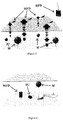
- the maritime floatation device has four deployment options as is shown in figures 1 to 4 . These being:
- the floatation device provides the ability to use remote firing devices above and below the water line utilising the timed and remote initiation features of the receiver(s).
- the floatation device consists of two main parts;
- the main floatation device components are:
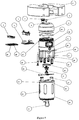
- FIG. 5 to 8 & 10 show the maritime floatation device of the invention.
- the maritime floatation device is supplied with a number of RFDs that enable the floatation device to be utilised as a maritime based remote firing system.
- the maritime floatation device is broken down into two main assemblies, namely receiver housing assembly (13) and basket assembly (28).
- the floatation device is designed to allow initiation of primarily shock-tube for use under water by preferably non-electric or electric initiation.
- Shock tube has the necessary properties to be deployed and operated under water at water depths without ingress of water impacting on the reliability.
- the floatation device provides a solution to be operated with electric and non-electric initiation due to existing user choice.
- Figure 9 shows the spooler used to setup shock tube spools for insertion into the basket assembly.
- the maritime floatation device is made up of two main assemblies:
- the main body assemblies contain several key components:
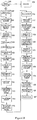
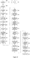
- a pre inspection drill 100 of the floatation device is undertaking, if the device fails the inspection it is quarantined 101. If inspection drill is passed then two shock tube (ST) receivers are prepared 102, one for timed initiation mode and the other for remote initiation mode. The lid of the receiver housing is removed 103. Selecting the correct top and bottom brackets for receivers 104 and securing the base bracket inside receiver housing 105. The first receiver that is used for the float separation is switched on and inserted 106. The second receiver that is used for the main charge is inserted 107. The top bracket is assembled 108 so as to clamp the receivers firmly into place. A length of shock tube is prepared 109 and shock tube is inserted in to the separation chamber 110. Shock tube is inserted in to the first receiver 111 after BIT test is completed.
- ST shock tube
- the spool is inserted into the basket 112. Taking the end with the pre-fitted detonator and passing through the three strain relief holes in the base of the basket. Adjusting the length of ST between the basket and detonator 113. The length of ST will be according to user requirements/specific tasks.
- the receiver housing legs are orientated and positioned with respective holes in the basket lid 124.
- the receiver housing is then pushed down onto the basket 125, Finally the cable ties are removed from the spool 126 and final top down checks completed.
- the floatation device is now ready to be deployed 127.
- a pre inspection drill 200 of the floatation device is undertaking, if the device fails the inspection it is quarantined 201. If inspection drill is passed then one ST receiver and one electric receiver are prepared 202, one ST receiver setup for timed initiation mode and the the one electric receiver for remote initiation mode 202. The lid of the receiver housing is removed 203. Selecting the correct top and bottom brackets for receivers 204 and securing the base bracket inside receiver housing 205. The first receiver that is used for the float separation is switched on and inserted 206. The second receiver that is used for the main charge is inserted 207. The top bracket is assembled 208 so as to clamp the receivers firmly into place. A length of shock tube is prepared 209 and shock tube is inserted in to the separation chamber 210. Shock tube is inserted in to the first receiver 211 after BIT test is completed.
- the spool is inserted into the basket 212. Taking the end with the pre-fitted detonator and passing through the three strain relief holes in the base of the basket. Adjusting the length of ST between the basket and detonator 213. The length of ST will be according to user requirements/specific tasks.
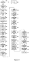
- a pre inspection drill 300 of the floatation device is undertaking, if the device fails the inspection it is quarantined 301. If inspection drill is passed then one shock tube (ST) receiver is prepared 302 for timed or remote initiation mode. The lid of the receiver housing is removed 303. Selecting the correct top and bottom brackets for receivers 304 and securing the base bracket inside receiver housing 305. The single ST receiver used for the main charge is inserted 306 into receiver location 2. The top bracket is assembled 307 so as to clamp the receiver firmly into place.
- ST shock tube
- the spool is inserted into the basket 308. Taking the end with the pre-fitted detonator and passing through the three strain relief holes in the base of the basket. Adjusting the length of ST between the basket and detonator 309. The length of ST will be according to user requirements/specific tasks.
- the receiver housing legs are orientated and positioned with respective holes in the basket lid 319.
- the receiver housing is then pushed down onto the basket 320.
- the cable ties are removed from the spool 321 and final top down checks completed.
- the floatation device is now ready to be deployed 322.
- a pre inspection drill 400 of the floatation device is undertaking, if the device fails the inspection it is quarantined 401. If inspection drill is passed then both electric receivers are prepared 402, one electric receiver setup for timed initiation mode and the one electric receiver for remote initiation mode 402. The lid of the receiver housing is removed 403.
- the first receiver that is used for the float separation is switched on and inserted 406.
- the second receiver that is used for the main charge is inserted 407.
- the top bracket is assembled 408 so as to clamp the receivers firmly into place.
- the spool is inserted into the basket 412. Taking the end with the pre-fitted detonator and passing through the three strain relief holes in the base of the basket. Adjusting the length of ST between the basket and detonator 413. The length of ST will be according to user requirements/specific tasks.
- a pre inspection drill 500 of the floatation device is undertaking, if the device fails the inspection it is quarantined 501. If inspection drill is passed then both electric receivers are prepared 502, one electric receiver setup for timed or remote initiation mode 502. The lid of the receiver housing is removed 503. Selecting the correct top and bottom brackets for receivers 504 and securing the base bracket inside receiver housing 505. The electric receiver used for the main charge is inserted into receiver location 2, 506. The top bracket is assembled 507 so as to clamp the receivers firmly into place.
- the spool is inserted into the basket 508. Taking the end with the pre-fitted detonator and passing through the three strain relief holes in the base of the basket. Adjusting the length of ST between the basket and detonator 509. The length of ST will be according to user requirements/specific tasks.
- the receiver housing is capable of holding a number of receivers that are secured internally using a bracket kit.
- the choice of receivers to be used within the floatation device is according to the operation being performed.
- the floatation device can be used to complete four major operational capabilities, for example as shown in figures 1 to 4 .
- a time delay is setup on the first receiver and is used to initiate the non-electric or electric explosive media,
- the initiation of the non-electric or electric explosive media causes the air to expand in the separation chamber forcing the blade assembly down.
- This motion cuts the nylon wire of the sacrificial tube severing the lanyard,
- the lanyard basket ejector arms are then forced open by the force of the launch springs and the angle of the basket lid lugs. With the basket tethered to the target the buoyant receiver housing floats to the surface to allow the user to complete remote initiation.
- the maritime floatation device can initiate weapon systems that prevent the need for expensive UUV combat rounds and if deployed as part of a weapon system on a UUV, the UUV is able to be re-used.
- the maritime floatation device allows the user to initiate a weapon system or explosive charge under remote command as single or multiple deployment that can be covert or overt.
- the maritime floatation device is required to enhance the operational capability of a land based RFD for operation within the increasing threats of the maritime environment and demand by associated maritime user groups. This provides a single solution to user groups meeting several operational capabilities.
- the maritime floatation device is required to extend the safety aspect and reliability of initiating detonators/detonating explosives.
- Safety in this context means to ensure the unintentional initiation of detonators during the setup/deployment of the maritime floatation device during operation. Unintentional initiation can be catastrophic.
- the maritime floatation device provides the ability for the user to conduct operations within very shallow water, shallow water and deep water.
- the maritime floatation device is able to be set-up and deployed for surface deployment so that it can be remotely initiated over distance.
- the maritime floatation device is able to be set-up and deployed for sub-surface deployment so that it will self-release to the surface using a timed delay.
- the maritime floatation device is capable of holding a combination of existing receivers to conduct the necessary operations aforementioned (see figures 1 to 4 ).
- the maritime floatation device is able to be deployed in covert or overt operations under or above the waterline within the hinterland.
- the solution shall be agile, quick to setup and basic to deploy.
- the maritime floatation device allows the user to deploy underwater without causing issues with diver buoyancy changing existing deployment strategies.
- the maritime floatation device allows single or multiple floats to be deployed to suit the operation and is remotely initiated individually or simultaneously under one control.
- the maritime floatation device is able to be deployed underwater by diver or by autonomous equipment.
- the maritime floatation device is able to be deployed above the water by boat, diver or by autonomous equipment.
- the maritime floatation device uses materials that do not impact on safety and the environment and allow it to be utilised at the required depths without water immersion.
- the maritime floatation device is quick to setup from its resting place to start of deployment
Landscapes
- Engineering & Computer Science (AREA)
- Chemical & Material Sciences (AREA)
- Combustion & Propulsion (AREA)
- Mechanical Engineering (AREA)
- Ocean & Marine Engineering (AREA)
- General Engineering & Computer Science (AREA)
- Aviation & Aerospace Engineering (AREA)
- Earth Drilling (AREA)
- Geophysics And Detection Of Objects (AREA)
- Emergency Lowering Means (AREA)
- Load-Engaging Elements For Cranes (AREA)
- Testing Or Calibration Of Command Recording Devices (AREA)
Claims (39)
- Ein maritimes Flotationsgerät (MFD) zur Verwendung von Fernzündvorrichtungen (RFD) oberhalb und unterhalb der Wasserlinie durch nicht-elektrische oder elektrische Zündung, das maritime Flotationsgerät (MFD) umfasst:a) ein Empfängergehäuse (13) mit einer Kombination von mindestens zwei Empfängern, die über einen Zündschlauch mit entsprechenden Sprengmitteln verbunden werden können, wobei ein Empfänger für eine zeitgesteuerte Auslösung zur Trennung und der zweite Empfänger für eine Fernauslösung oder eine zeitgesteuerte Auslösung eingerichtet sind, um die gewünschten erforderlichen Einsatzfähigkeiten des maritimen Flotationsgeräts (MFD) zu erbringen;b) ein ablösbares Korbgehäuse (26), das mit dem Empfängergehäuse (13) verbunden ist;c) Festhaltevorrichtung (25) zum Festhalten von zwei Gehäusen (13, 26) zusammen;d) eine Trennvorrichtung (24) zum Deaktivieren der Festhaltevorrichtung, um die Trennung des Empfängergehäuses (13) von dem Korbgehäuse (26) bei der Aktivierung der Trennvorrichtung (25) durch das von einem auslösezeitgesteuerten Empfänger ausgelöste Sprengmittel zu ermöglichen;e) mindestens ein Zündschlauch (ST) und eine innerhalb des Korbgehäuses (26) positionierbare Zündschlauchspule, wobei die Spule eine Länge des Zündschlauchs aufnimmt und umfasst, die mit dem zweiten Empfänger und mit Sprengmitteln derart verbindbar ist, dass eine Flexibilität beim Einsatz des maritimen Flotationsgeräts (MFD) zur Anpassung an die gewünschten Standardbetriebsverfahren ermöglicht wird; und/oderf) Schwimmer (44), die an dem Empfängergehäuse (13) derart befestigt werden können, dass das Empfängergehäuse (13) an die Oberfläche schwimmen kann, sobald das Empfängergehäuse (13) von dem Korbgehäuse (26) getrennt wird; wobei das maritime Flotationsgerät (MFD) eine nicht-elektrische oder elektrische Auslösung von Zündschläuchen mit Eigenschaften ermöglicht, die unter Wasser in Wassertiefen eingesetzt und betrieben werden können, ohne dass das Eindringen von Wasser die Zuverlässigkeit des maritimen Flotationsgeräts (MFD) beeinträchtigt.
- Das maritime Flotationsgerät (MFD) nach Anspruch 1, wobei das Empfängergehäuse (13) aus Materialien hergestellt ist, die Korrosion und magnetische Signalwirkung minimieren.
- Das maritime Flotationsgerät (MFD) nach Anspruch 2, wobei die Materialien eine Kombination aus Acetal-, Edelstahl- und Polycarbonatteilen sind.
- Das maritime Flotationsgerät (MFD), wie in irgendeinem der vorhergehenden Ansprüche beansprucht, wobei das Korbgehäuse (26) fähig ist, eine Länge von bis zu 500 m des Zündschlauchs auf der Spule derart zu halten, dass das maritime Flotationsgerät (MFD) bis zu Tiefen zwischen der Oberfläche und 400 m betätigt werden kann und eine Dehnung und ein Durchhängen zwischen den beiden Gehäusen (13, 26) ermöglicht, sobald die beiden Gehäuse (13, 26) des maritimen Flotationsgeräts (MFD) getrennt worden sind.
- Das maritime Flotationsgerät (MFD) wie in irgendeinem der vorhergehenden Ansprüche beansprucht, wobei das Empfängergehäuse (13) drehbar montierte, nach unten hängende Ejektorarme (45) aufweist, die zusammenwirkend mit an dem Korbgehäuse (26) befestigten Klauenrezeptorvorrichtung eingreifen, wobei die Ejektorarme (45) durch die Haltevorrichtungen derart in einer Klemmwirkung mit der Klauenrezeptorvorrichtung gehalten werden, dass die Empfänger- und Korbgehäuse (13, 26) zusammen lösbar festgehalten werden.
- Das maritime Flotationsgerät (MFD), wie in Anspruch 5 beansprucht, wobei die Klauenrezeptorvorrichtungen Haltevorsprünge (18) sind, die Haltevorsprünge (18) eine abgewinkelte Oberfläche umfassen, um das Lösen und Öffnen der Ejektorarme (45) bei der Deaktivierung der Festhaltevorrichtung durch die Trennvorrichtungen zu unterstützen, um es zu ermöglichen, dass sich die beiden Gehäuse (13, 26) voneinander abtrennen.
- Das maritime Flotationsgerät (MFD), wie in irgendeinem der vorhergehenden Ansprüche beansprucht, wobei das Empfängergehäuse (13) über einen Deckel (2) mit einer RRx-Aktivierungstaste (1) verfügt, um die Aktivierung der Empfänger innerhalb des Empfängergehäuses (13) auf Tastendruck zu ermöglichen.
- Das maritime Flotationsgerät (MFD), wie in Anspruch 7 beansprucht, wobei der Deckel (2) eine Öffnung (4) aufweist, die zur Aufnahme einer Antenne oder einer wasserdichten Kappe dient, wenn keine Antenne erforderlich ist.
- Das maritime Flotationsgerät (MFD), wie in Anspruch 8 beansprucht, wobei der Deckel (2) durch eine Verriegelungsschnur (20) am Gehäuse (13) befestigt ist, die Verriegelungsschnur (20) durch einen Verriegelungskanal (22) in das Gehäuse (13) eingefügt ist.
- Das maritime Flotationsgerät (MFD), wie in irgendeinem der vorhergehenden Ansprüche beansprucht, wobei das Empfängergehäuse (13) zwei Anzeigefenster (11) und zwei Empfängertasten (12) aufweist, so dass eine visuelle Inspektion der Empfängeranzeigen und ein externer Zugang zur Bedienung der im Inneren des Gehäuses (13) eingebauten Empfängern ermöglicht wird.
- Das maritime Flotationsgerät (MFD), wie in irgendeinem der vorhergehenden Ansprüche beansprucht, wobei das Empfängergehäuse (13) mindestens zwei im Abstand voneinander, nach unten hängende integrierte Beine mit festgehaltenen Auslösefedern (15) aus rostfreiem Stahl aufweist, wobei die Beine ausgerichtet sind und mit der Oberseite des Korbgehäuses (26) Kontakt haben, wenn das Empfängergehäuse (13) mit dem Gehäusekorb (26) verbunden ist, die festgehaltenen Federn (15) zusammengedrückt werden und unter Last stehen, wenn das Empfängergehäuse (13) mit dem Korbgehäuse (26) verbunden ist, und so ausgerichtet sind, dass sie bei Aktivierung der Trennvorrichtung eine Auslösekraft zur Trennung des Empfängergehäuses (13) vom Korbgehäuse (26) liefern.
- Das maritime Flotationsgerät (MFD), wie in Anspruch 11 beansprucht, bei dem vier in gleichem Abstand voneinander nach unten hängende integrierte Beine vorhanden sind.
- Das maritime Flotationsgerät (MFD), wie in irgendeinem der vorhergehenden Ansprüche beansprucht, wobei die Trennvorrichtung eine Messeranordnung (24) mit einer Schneidklinge aufweist, die so ausgebildet ist, dass sie durch das Empfängergehäuse (13) hindurchgeht, um die Festhalteeinrichtung zu deaktivieren, wobei die Messeranordnung (24) innerhalb des Empfängergehäuses (13) untergebracht und mit einer Trennungsauslösekammer innerhalb des Aufnahmegehäuses (13) verbunden ist, die Trennungsauslösekammer darin das Sprengmittel (in einem Fall über einen Zündschlauch verbunden) mit dem auslösezeitgesteuerten Empfänger derart enthält, so dass bei Aktivierung des auslösezeitgesteuerten Empfängers das Sprengmittel detoniert, um die Schneidklinge zu veranlassen, die Festhaltevorrichtung zu deaktivieren, wodurch die Ejektorarme (45) freigegeben und die festgehaltenen Federn (15) an den Beinen entspannt werden, wodurch das Empfängergehäuse (13) gezwungen wird, sich vom Korbgehäuse (26) zu trennen.
- Das maritime Flotationsgerät (MFD), wie in Anspruch 13 beansprucht, wobei die Festhaltevorrichtung, die die beiden Gehäuse (13, 26) ablösbar zusammenhält, ein längliches Element umfasst, das an den Ejektorarmen (45) befestigt werden kann, um die Ejektorarme (45) in einer Klemmposition an den Haltevorsprüngen (18) am Korbgehäuse (26) zu halten, wobei das längliche Element so angepasst ist, dass es von der Schneidklinge durchtrennt werden kann, um das Lösen der Ejektorarme (45) von den Haltevorsprüngen (18) zu unterstützen.
- Das maritime Flotationsgerät (MFD) wie in Anspruch 14 beansprucht, wobei das längliche Element ein Binder, eine Schnur, ein Draht, eine Schnur, ein Glied, eine Litze, eine Leine, ein Band, ein Kabel oder eine Schnur ist, das bzw. die durchtrennbar ist.
- Das maritime Flotationsgerät (MFD) wie in Anspruch 15 beansprucht, bei der das längliche Element so gespannt wird, dass die Ejektorarme (45) sicher an den Haltevorsprüngen (18) festgeklemmt werden.
- Das maritime Flotationsgerät (MFD), wie in Anspruch 16 beansprucht, wobei das längliche Element eine federgespannte Halteschlaufe (25) ist.
- Das maritime Flotationsgerät (MFD), wie in irgendeinem der vorhergehenden Ansprüche beansprucht, wobei das Empfängergehäuse (13) eine Stopfbuchsenplatte (16) und eine Stopfbuchse an der Unterseite des Empfängergehäuses (13) aufweist, wobei die Stopfbuchsenplatte (16) und die Stopfbuchse so angepasst sind, dass die Verbindung des Zündschlauchs von der Spule in das Empfängergehäuse (13) eintreten kann, wobei die Stopfbuchsenplatte (16) die Stopfbuchse aufnimmt, um eine Zugentlastung und eine wasserdichte Abdichtung zwischen dem Zündschlauch innerhalb des Empfängergehäuses (13) und dem Zündschlauch außerhalb des Empfängergehäuses (13) zu schaffen.
- Das maritime Flotationsgerät (MFD), wie in irgendeinem der vorhergehenden Ansprüche beansprucht, wobei das Empfängergehäuse (13) einen Hohlraum oder Hohlräume (14) zur allgemeinen Sicherung und Verankerung des maritimen Flotationsgeräts (MFD) aufweist.
- Das maritime Flotationsgerät (MFD), wie in irgendeinem der vorhergehenden Ansprüche beansprucht, wobei das Korbgehäuse (26) einen Deckel (19) aufweist, der an dem Korbgehäuse (26) durch eine Verriegelungsschnur befestigt ist, die in einen Verriegelungskanal an dem Korbgehäuse (26) eingeführt ist, wobei der Deckel (19) die Haltevorsprünge (18) aufweist.
- Das maritime Flotationsgerät (MFD), wie in Anspruch 20 beansprucht, wobei die Bodenplatte des Korbgehäuses (26) einen Schäkel (27) zur Verwendung beim Verankern oder Anbinden des Korbgehäuses (26) an den Meeresboden oder irgendeine andere Unterwassereinrichtung oder -vorrichtung aufweist, die sich zum Verankern oder Anbinden eignet.
- Das maritime Flotationsgerät (MFD), wie in Anspruch 21 beansprucht, wobei die Bodenplatte des Korbgehäuses (26) eine Vielzahl von Zündschlauch-Halteöffnungen umfasst, die eine Verriegelung des Zündschlauchs ermöglichen, um eine Zugentlastung zu schaffen.
- Das maritime Flotationsgerät (MFD), wie in irgendeinem der vorhergehenden Ansprüche beansprucht, wobei das Sprengmittel der Hauptladung ein Sprengzünder ist, der über einen Zündschlauch angeschlossen und gezündet werden kann.
- Das maritime Flotationsgerät (MFD), wie in irgendeinem der vorhergehenden Ansprüche beansprucht, wobei der Zündschlauch anschließbar und auslösbar ist entweder direkt von dem zweiten Empfänger, der in der Lage ist, den Zündschlauch auszulösen, oder über den zweiten Empfänger, der in der Lage ist, elektrische Zünder auszulösen.
- Das maritime Flotationsgerät (MFD), wie in irgendeinem der vorhergehenden Ansprüche beansprucht, wobei das Korbgehäuse (26) die Fähigkeit umfasst, eine elektrische Verbindung zum Zündschlauch zu ermöglichen.
- Das maritime Flotationsgerät (MFD), wie in irgendeinem der vorhergehenden Ansprüche beansprucht, wobei die Fähigkeit von elektrischer Verbindung des Zündschlauchs für Wassertiefen innerhalb der Oberfläche und 400 m geeignet ist und das Eindringen von Wasser nach dem Auslösen des Zünders verhindert.
- Das maritime Flotationsgerät (MFD), wie in irgendeinem der vorhergehenden Ansprüche beansprucht, wobei die elektrische Zündschlauchverbindung eine mechanische Befestigungsvorrichtung umfasst, um eine zuverlässige Auslösung des Zündschlauchs durch elektrische Auslösung zu ermöglichen, wobei die mechanische Befestigungsvorrichtung die Anordnung und den Ort des Zündschlauchs durch ein Rückhaltesystem derart festlegt, dass der Zündschlauch in der Nähe des elektrischen Zünders für eine zuverlässige Auslösung unter Wasser festgehalten wird.
- Das maritime Flotationsgerät (MFD), wie in irgendeinem der vorhergehenden Ansprüche beansprucht, wobei die Zündschlauchspule eine zweiteilige Aufwickelvorrichtung und eine Klemmvorrichtung (43) zur Sicherung während des Betriebs der Spule umfasst.
- Das maritime Flotationsgerät (MFD), wie in irgendeinem der vorhergehenden Ansprüche beansprucht, wobei der Schwimmer aus einem Ring oder Ringen (44) besteht, die Auftrieb und verbesserte Stabilität für das maritime Flotationsgerät (MFD) liefern.
- Das maritime Flotationsgerät (MFD), wie in Anspruch 29 beansprucht, wobei mehrere Schwimmerringe (44) zusammen oder unabhängig voneinander verwendet werden können.
- Das maritime Flotationsgerät (MFD), wie in Anspruch 30 beansprucht, wobei die Schwimmer (44) aus Auftriebsschaumstoff hergestellt sind.
- Das maritime Flotationsgerät (MFD), wie in irgendeinem der vorhergehenden Ansprüche beansprucht, wobei die mehreren Korbgehäuse (26) zusammengefügt und übereinander gestapelt werden können.
- Das maritime Flotationsgerät (MFD), wie in Anspruch 32 beansprucht, wobei die mehreren Korbgehäuse (26) mit kundenspezifischen Lösungen für Verankerungs- oder Anbindeoptionen verbunden werden können.
- Das maritime Flotationsgerät (MFD), wie in irgendeinem der vorhergehenden Ansprüche beansprucht, wobei das maritime Flotationsgerät (MFD) mit Hilfe von Permanentmagneten oder schaltbaren Magneten festgebunden werden kann.
- Ein Verfahren zum Aufbau eines maritimen Flotationsgeräts (MFD), wie in irgendeinem der vorhergehenden Ansprüche beansprucht, wobei das Verfahren bei Verwendung von zwei Zündschlauch-Empfängern die Schritte umfasst:a) Durchführung (100) eines Vor-Inspektionsdrills des maritimen Flotationsgeräts (MFD); wenn das maritime Flotationsgerät den Vor-Inspektionsdrill nicht besteht, wird es unter Quarantäne gestellt;b) Vorbereitung (102) von mindestens zwei Empfängern;c) Entfernen (103) des Deckels (2) des Empfängergehäuses (13) und Auswählen (104) der oberen und unteren Halterungen (5, 8) für Empfänger und Sichern der Grundhalterung innerhalb des Empfängergehäuses (13);d) Vorbereiten (109) einer Länge des Zündschlauchs von > 100 mm und Einführen (110) des Zündschlauchs in die Trennungsauslösekammer oder einer elektrischen Auslösevorrichtung innerhalb der Trennungsauslösekammer;e) Einschalten des auslösezeitgesteuerten Empfängers, der für die Schwimmertrennung verwendet wird;f) Einsetzen (111) des durch Fernsteuerung in Gang gesetzten Empfängers in das Empfängergehäuse (13);g) Festes Einspannen und Sichern an der Stelle von den Empfängern mit dem oberen Bügel (5);h) Einfügen der Trennungslänge vom Zündschlauch in den auslösezeitgesteuerten Empfänger nach Abschluss des BIT-Tests und der Konfiguration der Zeitsteuerung oder des Anschlusses einer elektrischen Trennungsauslösungsmethode von einem auslösezeitgesteuerten Empfänger nach Abschluss des BIT-Tests;i) Einsetzen (112) der Spule in das Korbgehäuse (26);j) das Ende des Zündschlauchs mit dem vormontierten Zünder ergreifen und durch die drei Zündschlauch-Halteöffnungen im Boden des Korbgehäuses (26) hindurchführen;k) Anpassen (113) der Länge des Zündschlauchs zwischen dem Korbgehäuse (26) und der Zündvorrichtung;l) Führen (114) des Zündschlauchs durch das mittlere Loch des Korbdeckels (19);m) Zusammenbau und Befestigung (116) des Deckels (19) am Korbgehäuse (26) unter Verwendung der Verriegelungsschnur und Sicherstellung, dass der Zündschlauch durch das Mittelloch im Deckel (19) gezogen worden ist;n) Sicherstellen, dass das Verriegelungsrad (17) der Empfängergehäusestopfbuchse offen ist;o) das freie Ende des Zündschlauchs ergreifen und das laufende Ende des Zündschlauchs so zurechtschneiden, dass ein trockener und rechtwinkliger Schnitt gemäß den Empfehlungen des Zündschlauch-Herstellers gewährleistet ist, bevor es in die Sprengmittel des oder der fernzündbaren Empfänger eingeführt wird;p) das frisch abgeschnittene Ende des Zündschlauchs ergreifen, das von der Mitte des Korbdeckels (19) innerhalb der Spule zugeführt worden ist, und durch das Stopfbuchsen-Sperrrad (17) und die Stopfbuchsenplatte (16) in das Empfängergehäuse (13) einführen, oder das freie Ende des Zündschlauchs in die elektrische Verbindung für die Fähigkeit der Zündschlauchauslösung einführen;q) Einschalten des ferngesteuerten Empfängers durch Drücken der externen Drucktaste;r) Einführen (117) des Zündschlauchs in den Empfänger nach Abschluss des BIT-Tests;s) Ausrichten (118) und Hinzufügen des/der Schwimmer(s) (44) auf dem Empfängergehäuse (13);t) Prüfung (119) eines O-Rings, der zur Abdichtung des Gehäusedeckels (2) verwendet wird;u) Ausrichten (120) des Deckels (2) zur Anpassung an das Empfängergehäuse (13) mit Hilfe der Verriegelungsschnur (20);v) Schließen (121) des Stopfbuchsensperrrads (17) am Boden des Empfängergehäuses, um eine wasserdichte Abdichtung zu schaffen;w) Zusammenbau (122) der Halteschlaufe mit dem Empfängergehäuse (13), so dass sich die Ejektorarme (45) frei bewegen können, aber die Spannung behalten, um die Ejektorarme (45) in der geschlossenen Klemmstellung zu halten;x) Zufuhr (123) von überschüssigem Zündschlauch auf die Spule;y) Ausrichten (124) und Positionieren der gefederten Beine mit entsprechenden Löchern im Korbgehäusedeckel (19); undz) Herunterdrücken (125) des Empfängergehäuses (13) auf das Korbgehäuse (26), um das Empfängergehäuse (13) am Korbgehäuse (26) zu befestigen, so dass das maritime Flotationsgerät (MFD) einsatzbereit ist.
- Das Verfahren zum Aufbau eines maritimen Flotationsgeräts (MFD), wie in Anspruch 35 beansprucht, wobei das Verfahren die Schritte der Verwendung eines Zündschlauchempfängers und eines elektrischen Empfängers umfasst.
- Das Verfahren zum Aufbau eines maritimen Flotationsgerät (MFD), wie in Anspruch 35 beansprucht, wobei das Verfahren den Schritt der Verwendung eines Zündschlauchempfängers umfasst.
- Das Verfahren zum Aufbau eines maritimen Flotationsgerät (MFD), wie in Anspruch 35 beansprucht, wobei das Verfahren den Schritt der Verwendung von zwei Zündschlauchempfängern umfasst.
- Das Verfahren zum Aufbau eines maritimen Flotationsgerät (MFD), wie in Anspruch 35 beansprucht, wobei das Verfahren den Schritt der Verwendung eines elektrischen Empfängers umfasst.
Applications Claiming Priority (1)
| Application Number | Priority Date | Filing Date | Title |
|---|---|---|---|
| PCT/NZ2015/050202 WO2017095234A1 (en) | 2015-12-02 | 2015-12-02 | Maritime floatation device |
Publications (3)
| Publication Number | Publication Date |
|---|---|
| EP3383735A1 EP3383735A1 (de) | 2018-10-10 |
| EP3383735A4 EP3383735A4 (de) | 2019-07-10 |
| EP3383735B1 true EP3383735B1 (de) | 2020-04-15 |
Family
ID=58797268
Family Applications (1)
| Application Number | Title | Priority Date | Filing Date |
|---|---|---|---|
| EP15909870.6A Active EP3383735B1 (de) | 2015-12-02 | 2015-12-02 | Maritime schwimmvorrichtung |
Country Status (10)
| Country | Link |
|---|---|
| US (1) | US11814148B2 (de) |
| EP (1) | EP3383735B1 (de) |
| JP (1) | JP6653019B2 (de) |
| KR (1) | KR102124522B1 (de) |
| AU (1) | AU2015416242B2 (de) |
| CA (1) | CA3005170C (de) |
| DK (1) | DK3383735T3 (de) |
| ES (1) | ES2794097T3 (de) |
| NZ (1) | NZ742154A (de) |
| WO (1) | WO2017095234A1 (de) |
Families Citing this family (7)
| Publication number | Priority date | Publication date | Assignee | Title |
|---|---|---|---|---|
| KR102124522B1 (ko) * | 2015-12-02 | 2020-06-19 | 마스 젠그란지 (엔제트) 리미티드 | 해양 부상 분리 디바이스 |
| DE102018103753B4 (de) * | 2018-02-20 | 2022-06-30 | Heinrich Hirdes Gmbh | Vorrichtung und Verfahren zur Beseitigung eines nicht explo-dierten Kampfmittels unter Wasser |
| CN114184350B (zh) * | 2021-11-17 | 2024-05-28 | 西安近代化学研究所 | 一种海上试验回收体的自扶正脱离装置 |
| CN114427809B (zh) * | 2021-12-14 | 2023-06-02 | 宜昌测试技术研究所 | 一种标准水雷战斗部 |
| CN114355479B (zh) * | 2022-03-16 | 2022-06-21 | 国家海洋技术中心 | 一种空投式台风海域气象海洋环境信息测量装置 |
| CN114919739A (zh) * | 2022-06-29 | 2022-08-19 | 海南艾锐奥科技有限公司 | 一种无人机落水引搜方法 |
| CN116930415B (zh) * | 2023-07-12 | 2026-03-24 | 中国地质调查局油气资源调查中心 | 一种水气界面温室气体通量监测装置及方法 |
Family Cites Families (21)
| Publication number | Priority date | Publication date | Assignee | Title |
|---|---|---|---|---|
| US3125953A (en) * | 1964-03-24 | Amplifier | ||
| US4020780A (en) * | 1969-11-05 | 1977-05-03 | The United States Of America As Represented By The Secretary Of The Navy | Mooring cable cutting system |
| US3946696A (en) * | 1969-12-05 | 1976-03-30 | The United States Of America As Represented By The Secretary Of The Navy | Automatically controlled magnetic minesweeping system |
| US3880103A (en) * | 1972-08-21 | 1975-04-29 | Us Navy | Tethered mine hunting system |
| US4037555A (en) * | 1976-06-30 | 1977-07-26 | Myer Berman | Buoy recovery technique |
| US4141295A (en) * | 1978-02-13 | 1979-02-27 | The United States Of America As Represented By The Secretary Of The Navy | Actuation mine simulator |
| SE8702854D0 (sv) * | 1986-07-03 | 1987-07-02 | British Aerospace | Explosiv anordning |
| DE3915577A1 (de) * | 1989-05-12 | 1990-11-15 | Rheinmetall Gmbh | Vorrichtung zur vernichtung von ankertauminen |
| US5173569A (en) * | 1991-07-09 | 1992-12-22 | The Ensign-Bickford Company | Digital delay detonator |
| DE19542377C2 (de) * | 1995-11-14 | 1999-11-25 | Rheinmetall W & M Gmbh | Anordnung zum Räumen von Ankertauminen |
| JP2783247B2 (ja) * | 1996-04-15 | 1998-08-06 | 日本電気株式会社 | ソノブイ及びこのソノブイを用いた水中探査方法 |
| AUPP021697A0 (en) * | 1997-11-06 | 1997-11-27 | Rocktek Limited | Radio detonation system |
| CA2548025C (en) * | 2003-12-01 | 2010-04-27 | Mas Zengrange (Nz) Ltd | Shock tube initiator |
| FR2882339B1 (fr) | 2005-02-21 | 2008-09-12 | Dcn Sa | Procede et dispositif d'identification et de neutralisation d'une mine sous-marine |
| KR101277002B1 (ko) * | 2010-07-20 | 2013-06-24 | 주식회사 마린이노텍 | 무인수상로봇 |
| GB2483861C (en) * | 2010-09-21 | 2019-01-30 | Ecs Special Projects Ltd | Attachment device and assemblies and systems using same |
| JP5695381B2 (ja) * | 2010-09-30 | 2015-04-01 | 株式会社神戸製鋼所 | プレス成形品の製造方法 |
| WO2012051604A2 (en) * | 2010-10-15 | 2012-04-19 | Mark Benson | Underwater neutralization system |
| DE102011121856A1 (de) * | 2011-12-21 | 2013-06-27 | Atlas Elektronik Gmbh | Kampfmittelräumgerät zum Räumen von Kampfmitteln, wie Seeminen, unter Wasser, Kampfmittelräumkombination mit unbemanntem Unterwasserfahrzeug und derartigem Kampfmittelräumgerät sowie Verfahren hierzu. |
| EP2912403B1 (de) * | 2012-10-23 | 2019-02-06 | Mas Zengrange (NZ) Limited | Empfänger für fernauslöser |
| KR102124522B1 (ko) * | 2015-12-02 | 2020-06-19 | 마스 젠그란지 (엔제트) 리미티드 | 해양 부상 분리 디바이스 |
-
2015
- 2015-12-02 KR KR1020187015066A patent/KR102124522B1/ko active Active
- 2015-12-02 WO PCT/NZ2015/050202 patent/WO2017095234A1/en not_active Ceased
- 2015-12-02 NZ NZ742154A patent/NZ742154A/en unknown
- 2015-12-02 AU AU2015416242A patent/AU2015416242B2/en active Active
- 2015-12-02 JP JP2018528661A patent/JP6653019B2/ja active Active
- 2015-12-02 US US15/773,164 patent/US11814148B2/en active Active
- 2015-12-02 DK DK15909870.6T patent/DK3383735T3/da active
- 2015-12-02 ES ES15909870T patent/ES2794097T3/es active Active
- 2015-12-02 CA CA3005170A patent/CA3005170C/en active Active
- 2015-12-02 EP EP15909870.6A patent/EP3383735B1/de active Active
Non-Patent Citations (1)
| Title |
|---|
| None * |
Also Published As
| Publication number | Publication date |
|---|---|
| KR20180088653A (ko) | 2018-08-06 |
| NZ742154A (en) | 2019-05-31 |
| ES2794097T3 (es) | 2020-11-17 |
| WO2017095234A1 (en) | 2017-06-08 |
| CA3005170A1 (en) | 2017-06-08 |
| US20210070409A1 (en) | 2021-03-11 |
| JP6653019B2 (ja) | 2020-02-26 |
| EP3383735A4 (de) | 2019-07-10 |
| AU2015416242A1 (en) | 2018-05-24 |
| AU2015416242B2 (en) | 2019-01-03 |
| JP2018535887A (ja) | 2018-12-06 |
| KR102124522B1 (ko) | 2020-06-19 |
| CA3005170C (en) | 2021-04-06 |
| EP3383735A1 (de) | 2018-10-10 |
| DK3383735T3 (da) | 2020-06-02 |
| US11814148B2 (en) | 2023-11-14 |
Similar Documents
| Publication | Publication Date | Title |
|---|---|---|
| EP3383735B1 (de) | Maritime schwimmvorrichtung | |
| JP5825538B2 (ja) | 水中の機雷などの兵器を撤去するための兵器撤去装置、その種の兵器撤去装置を備える無人潜水機並びにそのための方法 | |
| US8831393B2 (en) | Unmanned underwater vehicle and device for connection of an optical waveguide cable to an unmanned underwater vehicle | |
| US9677866B2 (en) | Attachment/release device and assemblies and systems using same | |
| US11591050B2 (en) | Sonobuoy deployable resources | |
| JP2813558B2 (ja) | 海中物体破壊方法 | |
| DK168203B1 (da) | Fremgangsmåde og apparat til installering af en anode i et katodisk beskyttelsessystem i en undersøisk konstruktion | |
| US3822660A (en) | Method and apparatus for salvaging a sunken vessel | |
| US8167670B1 (en) | Blow-off float vehicle recovery apparatus | |
| US6408763B1 (en) | Apparatus for land, sea, and air defense | |
| EP3945277A1 (de) | Universelle modulare vorrichtung zum kontrollierten und weiten abschuss von handgranaten und zündern und/oder verschiedenen hohlschäften mit/ohne sprengstoff im inneren | |
| US9016185B1 (en) | Weapon clearance appliance for clearing weapons, such as underwater mines, under water, unmanned underwater vehicle having a weapon clearance appliance of this kind, and method for this purpose | |
| US12179895B2 (en) | Explosive container | |
| US6230627B1 (en) | Method and apparatus for removing abandoned offshore fixed platform | |
| US4180351A (en) | Methods and apparatus for severing reinforced concrete pilings | |
| US3249014A (en) | Flotation and launching harness for water launched missiles | |
| US3315629A (en) | Underwater anchor gun device | |
| KR101404123B1 (ko) | 음향 코드를 이용한 수중 트리거 시스템 및 이를 이용한 수중 기폭방법 | |
| GB2578492A (en) | A device for attaching to a target | |
| NO318043B1 (no) | Framgangsmate og anordning for destruksjon av drivende sjominer | |
| JP2011122757A (ja) | 水中試験用爆破装置 | |
| US20160228994A1 (en) | Method and device for removing at least part of a sea platform | |
| KR101904885B1 (ko) | 파일 훅업 장치 | |
| WO2012051604A2 (en) | Underwater neutralization system | |
| KR200261835Y1 (ko) | 수중용 인명구조장치 |
Legal Events
| Date | Code | Title | Description |
|---|---|---|---|
| STAA | Information on the status of an ep patent application or granted ep patent |
Free format text: STATUS: THE INTERNATIONAL PUBLICATION HAS BEEN MADE |
|
| PUAI | Public reference made under article 153(3) epc to a published international application that has entered the european phase |
Free format text: ORIGINAL CODE: 0009012 |
|
| STAA | Information on the status of an ep patent application or granted ep patent |
Free format text: STATUS: REQUEST FOR EXAMINATION WAS MADE |
|
| 17P | Request for examination filed |
Effective date: 20180626 |
|
| AK | Designated contracting states |
Kind code of ref document: A1 Designated state(s): AL AT BE BG CH CY CZ DE DK EE ES FI FR GB GR HR HU IE IS IT LI LT LU LV MC MK MT NL NO PL PT RO RS SE SI SK SM TR |
|
| AX | Request for extension of the european patent |
Extension state: BA ME |
|
| DAV | Request for validation of the european patent (deleted) | ||
| DAX | Request for extension of the european patent (deleted) | ||
| A4 | Supplementary search report drawn up and despatched |
Effective date: 20190611 |
|
| RIC1 | Information provided on ipc code assigned before grant |
Ipc: B63G 7/02 20060101AFI20190604BHEP Ipc: F42B 3/10 20060101ALI20190604BHEP Ipc: F42D 5/04 20060101ALI20190604BHEP |
|
| GRAP | Despatch of communication of intention to grant a patent |
Free format text: ORIGINAL CODE: EPIDOSNIGR1 |
|
| STAA | Information on the status of an ep patent application or granted ep patent |
Free format text: STATUS: GRANT OF PATENT IS INTENDED |
|
| INTG | Intention to grant announced |
Effective date: 20191220 |
|
| GRAS | Grant fee paid |
Free format text: ORIGINAL CODE: EPIDOSNIGR3 |
|
| GRAJ | Information related to disapproval of communication of intention to grant by the applicant or resumption of examination proceedings by the epo deleted |
Free format text: ORIGINAL CODE: EPIDOSDIGR1 |
|
| GRAL | Information related to payment of fee for publishing/printing deleted |
Free format text: ORIGINAL CODE: EPIDOSDIGR3 |
|
| STAA | Information on the status of an ep patent application or granted ep patent |
Free format text: STATUS: REQUEST FOR EXAMINATION WAS MADE |
|
| GRAR | Information related to intention to grant a patent recorded |
Free format text: ORIGINAL CODE: EPIDOSNIGR71 |
|
| STAA | Information on the status of an ep patent application or granted ep patent |
Free format text: STATUS: GRANT OF PATENT IS INTENDED |
|
| GRAA | (expected) grant |
Free format text: ORIGINAL CODE: 0009210 |
|
| STAA | Information on the status of an ep patent application or granted ep patent |
Free format text: STATUS: THE PATENT HAS BEEN GRANTED |
|
| INTC | Intention to grant announced (deleted) | ||
| INTG | Intention to grant announced |
Effective date: 20200305 |
|
| AK | Designated contracting states |
Kind code of ref document: B1 Designated state(s): AL AT BE BG CH CY CZ DE DK EE ES FI FR GB GR HR HU IE IS IT LI LT LU LV MC MK MT NL NO PL PT RO RS SE SI SK SM TR |
|
| REG | Reference to a national code |
Ref country code: CH Ref legal event code: EP |
|
| REG | Reference to a national code |
Ref country code: DE Ref legal event code: R096 Ref document number: 602015050956 Country of ref document: DE |
|
| REG | Reference to a national code |
Ref country code: IE Ref legal event code: FG4D |
|
| REG | Reference to a national code |
Ref country code: AT Ref legal event code: REF Ref document number: 1256973 Country of ref document: AT Kind code of ref document: T Effective date: 20200515 |
|
| REG | Reference to a national code |
Ref country code: DK Ref legal event code: T3 Effective date: 20200527 |
|
| REG | Reference to a national code |
Ref country code: NL Ref legal event code: FP |
|
| REG | Reference to a national code |
Ref country code: SE Ref legal event code: TRGR |
|
| REG | Reference to a national code |
Ref country code: NO Ref legal event code: T2 Effective date: 20200415 |
|
| REG | Reference to a national code |
Ref country code: LT Ref legal event code: MG4D |
|
| PG25 | Lapsed in a contracting state [announced via postgrant information from national office to epo] |
Ref country code: LT Free format text: LAPSE BECAUSE OF FAILURE TO SUBMIT A TRANSLATION OF THE DESCRIPTION OR TO PAY THE FEE WITHIN THE PRESCRIBED TIME-LIMIT Effective date: 20200415 Ref country code: PT Free format text: LAPSE BECAUSE OF FAILURE TO SUBMIT A TRANSLATION OF THE DESCRIPTION OR TO PAY THE FEE WITHIN THE PRESCRIBED TIME-LIMIT Effective date: 20200817 Ref country code: FI Free format text: LAPSE BECAUSE OF FAILURE TO SUBMIT A TRANSLATION OF THE DESCRIPTION OR TO PAY THE FEE WITHIN THE PRESCRIBED TIME-LIMIT Effective date: 20200415 Ref country code: IS Free format text: LAPSE BECAUSE OF FAILURE TO SUBMIT A TRANSLATION OF THE DESCRIPTION OR TO PAY THE FEE WITHIN THE PRESCRIBED TIME-LIMIT Effective date: 20200815 Ref country code: GR Free format text: LAPSE BECAUSE OF FAILURE TO SUBMIT A TRANSLATION OF THE DESCRIPTION OR TO PAY THE FEE WITHIN THE PRESCRIBED TIME-LIMIT Effective date: 20200716 |
|
| REG | Reference to a national code |
Ref country code: AT Ref legal event code: MK05 Ref document number: 1256973 Country of ref document: AT Kind code of ref document: T Effective date: 20200415 |
|
| REG | Reference to a national code |
Ref country code: ES Ref legal event code: FG2A Ref document number: 2794097 Country of ref document: ES Kind code of ref document: T3 Effective date: 20201117 |
|
| PG25 | Lapsed in a contracting state [announced via postgrant information from national office to epo] |
Ref country code: RS Free format text: LAPSE BECAUSE OF FAILURE TO SUBMIT A TRANSLATION OF THE DESCRIPTION OR TO PAY THE FEE WITHIN THE PRESCRIBED TIME-LIMIT Effective date: 20200415 Ref country code: BG Free format text: LAPSE BECAUSE OF FAILURE TO SUBMIT A TRANSLATION OF THE DESCRIPTION OR TO PAY THE FEE WITHIN THE PRESCRIBED TIME-LIMIT Effective date: 20200715 Ref country code: HR Free format text: LAPSE BECAUSE OF FAILURE TO SUBMIT A TRANSLATION OF THE DESCRIPTION OR TO PAY THE FEE WITHIN THE PRESCRIBED TIME-LIMIT Effective date: 20200415 Ref country code: LV Free format text: LAPSE BECAUSE OF FAILURE TO SUBMIT A TRANSLATION OF THE DESCRIPTION OR TO PAY THE FEE WITHIN THE PRESCRIBED TIME-LIMIT Effective date: 20200415 |
|
| PG25 | Lapsed in a contracting state [announced via postgrant information from national office to epo] |
Ref country code: AL Free format text: LAPSE BECAUSE OF FAILURE TO SUBMIT A TRANSLATION OF THE DESCRIPTION OR TO PAY THE FEE WITHIN THE PRESCRIBED TIME-LIMIT Effective date: 20200415 |
|
| REG | Reference to a national code |
Ref country code: DE Ref legal event code: R097 Ref document number: 602015050956 Country of ref document: DE |
|
| PG25 | Lapsed in a contracting state [announced via postgrant information from national office to epo] |
Ref country code: SM Free format text: LAPSE BECAUSE OF FAILURE TO SUBMIT A TRANSLATION OF THE DESCRIPTION OR TO PAY THE FEE WITHIN THE PRESCRIBED TIME-LIMIT Effective date: 20200415 Ref country code: EE Free format text: LAPSE BECAUSE OF FAILURE TO SUBMIT A TRANSLATION OF THE DESCRIPTION OR TO PAY THE FEE WITHIN THE PRESCRIBED TIME-LIMIT Effective date: 20200415 Ref country code: CZ Free format text: LAPSE BECAUSE OF FAILURE TO SUBMIT A TRANSLATION OF THE DESCRIPTION OR TO PAY THE FEE WITHIN THE PRESCRIBED TIME-LIMIT Effective date: 20200415 Ref country code: RO Free format text: LAPSE BECAUSE OF FAILURE TO SUBMIT A TRANSLATION OF THE DESCRIPTION OR TO PAY THE FEE WITHIN THE PRESCRIBED TIME-LIMIT Effective date: 20200415 Ref country code: AT Free format text: LAPSE BECAUSE OF FAILURE TO SUBMIT A TRANSLATION OF THE DESCRIPTION OR TO PAY THE FEE WITHIN THE PRESCRIBED TIME-LIMIT Effective date: 20200415 |
|
| PLBE | No opposition filed within time limit |
Free format text: ORIGINAL CODE: 0009261 |
|
| STAA | Information on the status of an ep patent application or granted ep patent |
Free format text: STATUS: NO OPPOSITION FILED WITHIN TIME LIMIT |
|
| PG25 | Lapsed in a contracting state [announced via postgrant information from national office to epo] |
Ref country code: SK Free format text: LAPSE BECAUSE OF FAILURE TO SUBMIT A TRANSLATION OF THE DESCRIPTION OR TO PAY THE FEE WITHIN THE PRESCRIBED TIME-LIMIT Effective date: 20200415 Ref country code: PL Free format text: LAPSE BECAUSE OF FAILURE TO SUBMIT A TRANSLATION OF THE DESCRIPTION OR TO PAY THE FEE WITHIN THE PRESCRIBED TIME-LIMIT Effective date: 20200415 |
|
| 26N | No opposition filed |
Effective date: 20210118 |
|
| PG25 | Lapsed in a contracting state [announced via postgrant information from national office to epo] |
Ref country code: SI Free format text: LAPSE BECAUSE OF FAILURE TO SUBMIT A TRANSLATION OF THE DESCRIPTION OR TO PAY THE FEE WITHIN THE PRESCRIBED TIME-LIMIT Effective date: 20200415 |
|
| REG | Reference to a national code |
Ref country code: CH Ref legal event code: PL |
|
| PG25 | Lapsed in a contracting state [announced via postgrant information from national office to epo] |
Ref country code: MC Free format text: LAPSE BECAUSE OF FAILURE TO SUBMIT A TRANSLATION OF THE DESCRIPTION OR TO PAY THE FEE WITHIN THE PRESCRIBED TIME-LIMIT Effective date: 20200415 |
|
| PG25 | Lapsed in a contracting state [announced via postgrant information from national office to epo] |
Ref country code: IE Free format text: LAPSE BECAUSE OF NON-PAYMENT OF DUE FEES Effective date: 20201202 Ref country code: LU Free format text: LAPSE BECAUSE OF NON-PAYMENT OF DUE FEES Effective date: 20201202 |
|
| PG25 | Lapsed in a contracting state [announced via postgrant information from national office to epo] |
Ref country code: CH Free format text: LAPSE BECAUSE OF NON-PAYMENT OF DUE FEES Effective date: 20201231 Ref country code: LI Free format text: LAPSE BECAUSE OF NON-PAYMENT OF DUE FEES Effective date: 20201231 |
|
| PG25 | Lapsed in a contracting state [announced via postgrant information from national office to epo] |
Ref country code: TR Free format text: LAPSE BECAUSE OF FAILURE TO SUBMIT A TRANSLATION OF THE DESCRIPTION OR TO PAY THE FEE WITHIN THE PRESCRIBED TIME-LIMIT Effective date: 20200415 Ref country code: MT Free format text: LAPSE BECAUSE OF FAILURE TO SUBMIT A TRANSLATION OF THE DESCRIPTION OR TO PAY THE FEE WITHIN THE PRESCRIBED TIME-LIMIT Effective date: 20200415 Ref country code: CY Free format text: LAPSE BECAUSE OF FAILURE TO SUBMIT A TRANSLATION OF THE DESCRIPTION OR TO PAY THE FEE WITHIN THE PRESCRIBED TIME-LIMIT Effective date: 20200415 |
|
| PG25 | Lapsed in a contracting state [announced via postgrant information from national office to epo] |
Ref country code: MK Free format text: LAPSE BECAUSE OF FAILURE TO SUBMIT A TRANSLATION OF THE DESCRIPTION OR TO PAY THE FEE WITHIN THE PRESCRIBED TIME-LIMIT Effective date: 20200415 |
|
| PGFP | Annual fee paid to national office [announced via postgrant information from national office to epo] |
Ref country code: DE Payment date: 20251211 Year of fee payment: 11 |
|
| PGFP | Annual fee paid to national office [announced via postgrant information from national office to epo] |
Ref country code: GB Payment date: 20251023 Year of fee payment: 11 |
|
| PGFP | Annual fee paid to national office [announced via postgrant information from national office to epo] |
Ref country code: IT Payment date: 20251223 Year of fee payment: 11 Ref country code: DK Payment date: 20251224 Year of fee payment: 11 |
|
| PGFP | Annual fee paid to national office [announced via postgrant information from national office to epo] |
Ref country code: NL Payment date: 20251219 Year of fee payment: 11 Ref country code: FR Payment date: 20251229 Year of fee payment: 11 |
|
| PGFP | Annual fee paid to national office [announced via postgrant information from national office to epo] |
Ref country code: BE Payment date: 20251219 Year of fee payment: 11 |
|
| PGFP | Annual fee paid to national office [announced via postgrant information from national office to epo] |
Ref country code: SE Payment date: 20251219 Year of fee payment: 11 |
|
| PGFP | Annual fee paid to national office [announced via postgrant information from national office to epo] |
Ref country code: ES Payment date: 20260130 Year of fee payment: 11 |
|
| PGFP | Annual fee paid to national office [announced via postgrant information from national office to epo] |
Ref country code: NO Payment date: 20251230 Year of fee payment: 11 |