EP3383642B1 - Herstellungsverfahren einer mehrschichtplatte aus verbundwerkstoff - Google Patents
Herstellungsverfahren einer mehrschichtplatte aus verbundwerkstoff Download PDFInfo
- Publication number
- EP3383642B1 EP3383642B1 EP16837982.4A EP16837982A EP3383642B1 EP 3383642 B1 EP3383642 B1 EP 3383642B1 EP 16837982 A EP16837982 A EP 16837982A EP 3383642 B1 EP3383642 B1 EP 3383642B1
- Authority
- EP
- European Patent Office
- Prior art keywords
- slab
- mat
- laying
- assembly
- multilayer
- Prior art date
- Legal status (The legal status is an assumption and is not a legal conclusion. Google has not performed a legal analysis and makes no representation as to the accuracy of the status listed.)
- Not-in-force
Links
- 238000004519 manufacturing process Methods 0.000 title claims description 17
- 239000002131 composite material Substances 0.000 title claims description 14
- 230000002787 reinforcement Effects 0.000 claims description 36
- 238000000034 method Methods 0.000 claims description 31
- 229920005989 resin Polymers 0.000 claims description 19
- 239000011347 resin Substances 0.000 claims description 19
- 239000004840 adhesive resin Substances 0.000 claims description 15
- 229920006223 adhesive resin Polymers 0.000 claims description 15
- 239000004575 stone Substances 0.000 claims description 13
- 239000011152 fibreglass Substances 0.000 claims description 12
- 239000003822 epoxy resin Substances 0.000 claims description 4
- LNEPOXFFQSENCJ-UHFFFAOYSA-N haloperidol Chemical compound C1CC(O)(C=2C=CC(Cl)=CC=2)CCN1CCCC(=O)C1=CC=C(F)C=C1 LNEPOXFFQSENCJ-UHFFFAOYSA-N 0.000 claims description 4
- 238000010438 heat treatment Methods 0.000 claims description 4
- 229920000647 polyepoxide Polymers 0.000 claims description 4
- 238000005406 washing Methods 0.000 claims description 3
- 238000010792 warming Methods 0.000 claims 1
- 101100495270 Caenorhabditis elegans cdc-26 gene Proteins 0.000 description 10
- 239000010410 layer Substances 0.000 description 10
- 238000010586 diagram Methods 0.000 description 4
- 230000035800 maturation Effects 0.000 description 4
- 239000000463 material Substances 0.000 description 3
- 239000002184 metal Substances 0.000 description 3
- 239000002759 woven fabric Substances 0.000 description 3
- 238000005253 cladding Methods 0.000 description 2
- 239000004744 fabric Substances 0.000 description 2
- GNFTZDOKVXKIBK-UHFFFAOYSA-N 3-(2-methoxyethoxy)benzohydrazide Chemical compound COCCOC1=CC=CC(C(=O)NN)=C1 GNFTZDOKVXKIBK-UHFFFAOYSA-N 0.000 description 1
- 239000000853 adhesive Substances 0.000 description 1
- 230000001070 adhesive effect Effects 0.000 description 1
- 239000012790 adhesive layer Substances 0.000 description 1
- 230000000712 assembly Effects 0.000 description 1
- 238000000429 assembly Methods 0.000 description 1
- 230000015572 biosynthetic process Effects 0.000 description 1
- 238000010276 construction Methods 0.000 description 1
- 230000001419 dependent effect Effects 0.000 description 1
- 238000001035 drying Methods 0.000 description 1
- 239000000428 dust Substances 0.000 description 1
- 238000009408 flooring Methods 0.000 description 1
- 238000005470 impregnation Methods 0.000 description 1
- 239000004579 marble Substances 0.000 description 1
- 230000013011 mating Effects 0.000 description 1
- 239000004033 plastic Substances 0.000 description 1
- 230000001737 promoting effect Effects 0.000 description 1
- 238000000926 separation method Methods 0.000 description 1
- 230000037303 wrinkles Effects 0.000 description 1
Images


Classifications
-
- B—PERFORMING OPERATIONS; TRANSPORTING
- B32—LAYERED PRODUCTS
- B32B—LAYERED PRODUCTS, i.e. PRODUCTS BUILT-UP OF STRATA OF FLAT OR NON-FLAT, e.g. CELLULAR OR HONEYCOMB, FORM
- B32B3/00—Layered products comprising a layer with external or internal discontinuities or unevennesses, or a layer of non-planar shape; Layered products comprising a layer having particular features of form
- B32B3/10—Layered products comprising a layer with external or internal discontinuities or unevennesses, or a layer of non-planar shape; Layered products comprising a layer having particular features of form characterised by a discontinuous layer, i.e. formed of separate pieces of material
- B32B3/12—Layered products comprising a layer with external or internal discontinuities or unevennesses, or a layer of non-planar shape; Layered products comprising a layer having particular features of form characterised by a discontinuous layer, i.e. formed of separate pieces of material characterised by a layer of regularly- arranged cells, e.g. a honeycomb structure
-
- B—PERFORMING OPERATIONS; TRANSPORTING
- B32—LAYERED PRODUCTS
- B32B—LAYERED PRODUCTS, i.e. PRODUCTS BUILT-UP OF STRATA OF FLAT OR NON-FLAT, e.g. CELLULAR OR HONEYCOMB, FORM
- B32B15/00—Layered products comprising a layer of metal
- B32B15/14—Layered products comprising a layer of metal next to a fibrous or filamentary layer
-
- B—PERFORMING OPERATIONS; TRANSPORTING
- B32—LAYERED PRODUCTS
- B32B—LAYERED PRODUCTS, i.e. PRODUCTS BUILT-UP OF STRATA OF FLAT OR NON-FLAT, e.g. CELLULAR OR HONEYCOMB, FORM
- B32B37/00—Methods or apparatus for laminating, e.g. by curing or by ultrasonic bonding
- B32B37/14—Methods or apparatus for laminating, e.g. by curing or by ultrasonic bonding characterised by the properties of the layers
- B32B37/146—Methods or apparatus for laminating, e.g. by curing or by ultrasonic bonding characterised by the properties of the layers whereby one or more of the layers is a honeycomb structure
-
- B—PERFORMING OPERATIONS; TRANSPORTING
- B32—LAYERED PRODUCTS
- B32B—LAYERED PRODUCTS, i.e. PRODUCTS BUILT-UP OF STRATA OF FLAT OR NON-FLAT, e.g. CELLULAR OR HONEYCOMB, FORM
- B32B9/00—Layered products comprising a layer of a particular substance not covered by groups B32B11/00 - B32B29/00
- B32B9/002—Layered products comprising a layer of a particular substance not covered by groups B32B11/00 - B32B29/00 comprising natural stone or artificial stone
-
- B—PERFORMING OPERATIONS; TRANSPORTING
- B32—LAYERED PRODUCTS
- B32B—LAYERED PRODUCTS, i.e. PRODUCTS BUILT-UP OF STRATA OF FLAT OR NON-FLAT, e.g. CELLULAR OR HONEYCOMB, FORM
- B32B9/00—Layered products comprising a layer of a particular substance not covered by groups B32B11/00 - B32B29/00
- B32B9/04—Layered products comprising a layer of a particular substance not covered by groups B32B11/00 - B32B29/00 comprising such particular substance as the main or only constituent of a layer, which is next to another layer of the same or of a different material
- B32B9/047—Layered products comprising a layer of a particular substance not covered by groups B32B11/00 - B32B29/00 comprising such particular substance as the main or only constituent of a layer, which is next to another layer of the same or of a different material made of fibres or filaments
-
- B—PERFORMING OPERATIONS; TRANSPORTING
- B32—LAYERED PRODUCTS
- B32B—LAYERED PRODUCTS, i.e. PRODUCTS BUILT-UP OF STRATA OF FLAT OR NON-FLAT, e.g. CELLULAR OR HONEYCOMB, FORM
- B32B2260/00—Layered product comprising an impregnated, embedded, or bonded layer wherein the layer comprises an impregnation, embedding, or binder material
- B32B2260/04—Impregnation, embedding, or binder material
- B32B2260/046—Synthetic resin
-
- B—PERFORMING OPERATIONS; TRANSPORTING
- B32—LAYERED PRODUCTS
- B32B—LAYERED PRODUCTS, i.e. PRODUCTS BUILT-UP OF STRATA OF FLAT OR NON-FLAT, e.g. CELLULAR OR HONEYCOMB, FORM
- B32B2262/00—Composition or structural features of fibres which form a fibrous or filamentary layer or are present as additives
- B32B2262/10—Inorganic fibres
- B32B2262/101—Glass fibres
-
- B—PERFORMING OPERATIONS; TRANSPORTING
- B32—LAYERED PRODUCTS
- B32B—LAYERED PRODUCTS, i.e. PRODUCTS BUILT-UP OF STRATA OF FLAT OR NON-FLAT, e.g. CELLULAR OR HONEYCOMB, FORM
- B32B2305/00—Condition, form or state of the layers or laminate
- B32B2305/02—Cellular or porous
- B32B2305/024—Honeycomb
-
- B—PERFORMING OPERATIONS; TRANSPORTING
- B32—LAYERED PRODUCTS
- B32B—LAYERED PRODUCTS, i.e. PRODUCTS BUILT-UP OF STRATA OF FLAT OR NON-FLAT, e.g. CELLULAR OR HONEYCOMB, FORM
- B32B2318/00—Mineral based
- B32B2318/04—Stone
-
- B—PERFORMING OPERATIONS; TRANSPORTING
- B32—LAYERED PRODUCTS
- B32B—LAYERED PRODUCTS, i.e. PRODUCTS BUILT-UP OF STRATA OF FLAT OR NON-FLAT, e.g. CELLULAR OR HONEYCOMB, FORM
- B32B2419/00—Buildings or parts thereof
-
- B—PERFORMING OPERATIONS; TRANSPORTING
- B32—LAYERED PRODUCTS
- B32B—LAYERED PRODUCTS, i.e. PRODUCTS BUILT-UP OF STRATA OF FLAT OR NON-FLAT, e.g. CELLULAR OR HONEYCOMB, FORM
- B32B2419/00—Buildings or parts thereof
- B32B2419/04—Tiles for floors or walls
-
- B—PERFORMING OPERATIONS; TRANSPORTING
- B32—LAYERED PRODUCTS
- B32B—LAYERED PRODUCTS, i.e. PRODUCTS BUILT-UP OF STRATA OF FLAT OR NON-FLAT, e.g. CELLULAR OR HONEYCOMB, FORM
- B32B2479/00—Furniture
-
- B—PERFORMING OPERATIONS; TRANSPORTING
- B32—LAYERED PRODUCTS
- B32B—LAYERED PRODUCTS, i.e. PRODUCTS BUILT-UP OF STRATA OF FLAT OR NON-FLAT, e.g. CELLULAR OR HONEYCOMB, FORM
- B32B2607/00—Walls, panels
-
- B—PERFORMING OPERATIONS; TRANSPORTING
- B32—LAYERED PRODUCTS
- B32B—LAYERED PRODUCTS, i.e. PRODUCTS BUILT-UP OF STRATA OF FLAT OR NON-FLAT, e.g. CELLULAR OR HONEYCOMB, FORM
- B32B37/00—Methods or apparatus for laminating, e.g. by curing or by ultrasonic bonding
- B32B37/02—Methods or apparatus for laminating, e.g. by curing or by ultrasonic bonding characterised by a sequence of laminating steps, e.g. by adding new layers at consecutive laminating stations
-
- B—PERFORMING OPERATIONS; TRANSPORTING
- B32—LAYERED PRODUCTS
- B32B—LAYERED PRODUCTS, i.e. PRODUCTS BUILT-UP OF STRATA OF FLAT OR NON-FLAT, e.g. CELLULAR OR HONEYCOMB, FORM
- B32B37/00—Methods or apparatus for laminating, e.g. by curing or by ultrasonic bonding
- B32B37/10—Methods or apparatus for laminating, e.g. by curing or by ultrasonic bonding characterised by the pressing technique, e.g. using action of vacuum or fluid pressure
- B32B37/1018—Methods or apparatus for laminating, e.g. by curing or by ultrasonic bonding characterised by the pressing technique, e.g. using action of vacuum or fluid pressure using only vacuum
-
- B—PERFORMING OPERATIONS; TRANSPORTING
- B32—LAYERED PRODUCTS
- B32B—LAYERED PRODUCTS, i.e. PRODUCTS BUILT-UP OF STRATA OF FLAT OR NON-FLAT, e.g. CELLULAR OR HONEYCOMB, FORM
- B32B38/00—Ancillary operations in connection with laminating processes
- B32B38/08—Impregnating
Definitions
- the present invention generally finds application in the field of composite materials, particularly for use in the building and furnishing industries, and particularly relates to a method of making a multilayer panel made of composite material
- Multilayer panel made of composite materials have been long known to be used as internal and external cladding of surface walls in the building and furnishing industries.
- Such panels typically comprise at least one stone slab of predetermined thickness, which is bonded to at least one reinforcement element adapted to impart strength to the slab while maintaining a low weight thereof.
- the reinforcement element comprises a metal or synthetic central core having a three-dimensional structure, e.g. a honeycomb structure, composed of cells and a pair of lattice sheets, adapted to be bonded to the flat surfaces of the core.
- a three-dimensional structure e.g. a honeycomb structure, composed of cells and a pair of lattice sheets, adapted to be bonded to the flat surfaces of the core.
- the reinforcement element is bonded to the slab at one of the sheets with one of the free surfaces of the slab.
- a first drawback of this arrangement is that the sheets of the reinforcement element must conform with the plan shape of the central core and are not easily adapted to the surface of the slab on which they have to be bonded, especially if the latter has projections and irregularities. This will result in imperfect adhesion of the reinforcement element to the slab, and will involve the risk that the latter may separate when the panel has been mounted.
- a further drawback is that finished reinforcement elements are quite expensive and will add to the overall cost of the finished panel.
- IT1385520 discloses a method of making multilayer panels as described hereinabove, which comprises a first step of providing a stone slab and a step of laying a fiberglass sheet on one of the faces of the slab with the interposition of a resin.
- a reinforcement element with a central core having a surface covered with an additional fiberglass sheet and a free surface is bonded to the first fiberglass sheet and then to the slab using the previously laid resin.
- the panel so formed is first introduced into a hermetically sealed plastic bag to create vacuum and then in a furnace for the resin to be cured by heating.
- a first drawback of this prior art arrangement is that the reinforcement element in use is purchased in an almost entirely finished form, and cannot obviate the aforementioned drawbacks.
- the method has no intermediate step for promoting adhesion between the parts of the reinforcement element, the sheets and the slab, which will maintain a high risk of separation thereof after assembly.
- a further drawback is that the plant for carrying out the present method is required to comprise a furnace for heating and curing the resin, which will add to the overall manufacturing costs.
- WO 2012/000893 A1 discloses another method for producing a slab of stone material which is reinforced by a naked honeycomb structure without covering skins having empty cells, by at least one woven fabric made of fiberglass and by a structural resin characterized in that it comprises the following steps: pouring said structural resin on a face of a first woven fabric until impregnation of said fabric; making said honeycomb structure to rest on said structural resin impregnated face of fabric, and performing a first warm maturation of the resin; adhering the open face of the honeycomb obtained by said first maturation, to the back of said stone slab by means of the structural resin, and performing a second maturation of the obtained assembled article, wherein the open face of the honeycomb structure previously maturated is adhered to a second woven fabric which is already placed on the back of the stone slab and then impregnated with the structural resin, characterized in that in the maturation the assembled article is warmed up, preferably in a suitable oven, for a given time, temperature and pressure, preferably at a temperature comprised between
- the technical problem addressed by the invention may be deemed to consist in providing a method of making a multilayer panel that can improve adhesion of the reinforcement element with the sheet mats and the slab, thereby reducing the overall manufacturing costs.
- the object of the present invention is to solve the above mentioned technical problem and obviate the above discussed drawback, by providing a method of making a multilayer panel made of composite material that is highly efficient and relatively cost-effective.
- a particular object of the present invention is to provide a method of making a multilayer panel made of composite material that improves adhesion of the reinforcement element to the stone slab.
- Another object of the present invention is to provide a method of making a multilayer panel made of composite material that has a particularly low cost.
- a further object of the present invention is to provide a method of making a multilayer panel made of composite material that is particularly simple.
- Yet another object of the present invention is to provide a method as described above that allow the panel to be formed through a small number of steps.
- a multilayer panel made of composite material may be formed, in which the parts are optimally bonded together. Furthermore, the method has the advantage of being particularly simple and of reducing the overall manufacturing costs for the panel.
- the permanence times of the various multilayer assemblies have a substantially equal average duration, ranging from 8 h to 15 h, about 12 h.
- the adhesive resin is selected from the group comprising two-component epoxy resins.
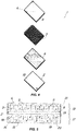
- FIGS. 1 and 2 show a method of making a multilayer panel made of composite material, which is suitable for use, preferably but without limitation, in the building and furnishing industries, not only for ground-based constructions, but also for nautical and aeronautical engineering.
- the multilayer panel made of composite material obtained with the method of the invention comprises at least one slab 2 made of a stone material such as marble or the like, and at least one reinforcement layer 3, having a three-dimensional honeycomb structure, which is bonded to the slab 2.
- the panel 1 may be used as cladding or flooring for walls and surfaces, for residential, industrial or marine applications, e.g. for interior furnishings of yachts, and may be attached to respective surfaces by appropriate high-strength adhesives or mechanical fastener means.
- the peculiar feature of the panel 1 is that the reinforcement element 3 imparts high mechanical strength to the slab 2, thereby preventing breaking or detachment thereof, and allowing the panel 1 to have a very light-weight structure.
- the method comprises a step of a) providing a first sheet-like fiberglass mat 4 and laying it on a first support plan P 1 .
- the first mat 4 has a predetermined plan shape.
- the first mat 4 is initially rolled up and the operator in charge of making the panel 1 will have to unroll it above the support plan P 1 and cut a portion of desired size therefrom.
- the operator shall lay the first mat 4 on the support plan P 1 while avoiding the formation of wrinkles or gathers thereof, which might affect the later steps of forming the panel 1.
- a second step is provided of b) laying a first layer of adhesive resin 5 on the top face 6 of the first mat 4, i.e. the face that does not contact the support plan P 1 , as shown in Fig. 3b .
- the adhesive resin 5 may be selected from the group comprising two-component epoxy resins and will be laid upon the first mat 4 until the latter is entirely impregnated therewith.
- the method comprises a step of c) providing a three-dimensional honeycomb reinforcement element 3 whose plan size is slightly smaller than the first mat 4, as shown in FIG. 3c .
- the reinforcement element 3 substantially corresponds to the metal core of common available honeycomb panels.
- the reinforcement element 3 is laid over the first mat 4 until it is at least partially embedded in the first layer of adhesive resin 5 and forms therewith a first assembly 7 with a free upper face 8.
- the step c) is followed by a step of d) overlaying the first assembly 7 with an impermeable sheet T sealingly lying over the first support plan P 1 and defining a watertight cavity C, as shown in FIG. 3d .
- the sheet T is mounted to a support B which is adapted to lie over the first assembly 7 and comprises a top opening A whose purpose will be better explained hereinafter.
- a step will follow, of e) connecting the cavity C that contains the first assembly 7 to a vacuum source for a first predetermined time interval to promote adhesion of the reinforcement element 3 to the first mat 4, as shown in FIG. 3d .
- the vacuum source may comprise a suction pump and the cavity C may be connected thereto through the top opening A formed on the support B.
- the support B with the impermeable sheet T may be used with different types of support surfaces without altering the desired vacuum conditions and may have standard sizes, allowing it to overlap reinforcement elements 3 of different sizes.
- this arrangement allows the operator to create vacuum by directly acting on the support plan P 1 , without moving the reinforcement element 1 being processed.
- a step is carried out of f) providing a stone slab 2 whose size substantially corresponds to that of the first assembly 7 and laying it over a second support plan P 2 , as clearly shown in FIG. 3e .
- a step may be envisaged of l) leveling and reducing the surface ruggedness of the face 10 of the slab 2, for improved adhesion of the second mat 9.
- a step is also provided, as shown in FIG. 3f , of g) providing a second mat 9 and laying it over the slab 2, particularly over the free face 10 of the latter, which does not contact the second support plan P 2 .
- the second mat 9, like the first mat, is made of fiberglass and has substantially the same size as the stone slab 2.
- a step may be provided of m) washing the free face 10 of the slab 2 with a high-pressure waterjet treatment machine using a high-pressure pump, not shown. Namely, this machine is connected to a pump having a pressure of about 2000 bar.
- a step is later provided, as shown in FIG. 3g , of h) laying a second layer of adhesive resin 11 on the second mat 9 to impregnate it and promote its adhesion to the slab 2 to define a second assembly 12.
- the resin 11 that is used for bonding the second mt 9 may also be selected from the group comprising two-component epoxy resins.
- the surface of the latter may be leveled and its ruggedness may be substantially smoothened out.
- the above discussed washing step m) can remove dust from the free face 10 of the slab 2 and create surface loops thereon to increase the adhesion surface with the second resin layer 11 laid during the step h).
- a step is provided of i) turning the first assembly 7 upside down and laying it on the second assembly 12, as shown in FIG. 3h .
- the first assembly 7 is laid over the second assembly 12 with its free face 8 at least partially embedded in the second layer of adhesive resin 11 to obtain a third assembly 13.
- the use of the second resin layer 11 to bond both the second mat 9 to the slab 2 and the first assembly 7 to the second assembly 12 can reduce the total amount of resin required to form the panel 1 and the overall time for making it.
- the method comprises a step of j) overlaying the third assembly 13 with an impermeable sheet T sealingly lying over the second support plan P 2 and defining a cavity C.
- a step will follow, of k) connecting the cavity C that contains the third assembly 13 to a vacuum source for a second predetermined time interval to promote adhesion of the reinforcement element 3 to the first mat 4 and the second mat 9 and obtain a finished multilayer panel 1, as shown in FIG. 3i .
- the impermeable sheet T is mounted to a rigid support B having a top opening A for connection of the cavity C with the vacuum source.
- Steps a) to k) are carried out at ambient temperature and steps e) and k) may have a substantially equal average duration, ranging from 8h to 15h, substantially close to 12h.
- adhesion of the reinforcement element 3 to the slab 2 is only improved by creating vacuum, without changing the temperature of the adhesive resin.
- steps e) and k) of creating vacuum on the first assembly 7 and the third assembly 13 respectively within the cavity C may be carried out at a constant pressure, substantially close to 0.6 bar.
- the method may comprise, prior to the step of k) creating vacuum, a step of n)providing a third sheet-like fiberglass mat 14 of substantially the same size as the slab 2.
- the step n) includes lying a third layer of adhesive resin 15 on the third mat 14 and is followed by a step of o) overlying the third layer of resin 15 with a second honeycomb reinforcement element 16 to obtain a fourth assembly 17.
- the support B with the sheet T is laid over the fourth assembly 17 to define the cavity C and is connected to the vacuum source, similar to what has been discussed above for the previous steps e) and k), for a third predetermined time interval, to facilitate adhesion between the third mat 14 and the second honeycomb reinforcement element 16.
- a step is further provided of p) providing a fourth fiberglass mat 18 of substantially the same size as the slab 2 and a step is provided of laying the fourth mat 18 on the free face 19 of the slab 2 of the third assembly 13 obtained in the step i) of the original method.
- the step q) is followed by a step of r) laying a fourth layer of adhesive layer 20 on the fourth mat 18 to impregnate it and promote bonding thereof to the slab 2, and by a step of s) laying the second honeycomb element 16 on the fourth mat 18 to promote bonding of the slab 2 of the intermediate panel 21, as shown in FIG. 5 .
- the method may include, downstream from the step k), a step of t) detaching the slab 2 of the intermediate panel 21 to obtain a pair of half-panels 1', not shown, each with a half-plate 2' having half the thickness of the slab 2 and with a corresponding reinforcement element 3, 16.
- the stone slabs and the reinforcement elements may have different shapes, sizes and thicknesses.
- the reinforcement element 3 may comprise holes located in predetermined positions for receiving respective bushings.
- the bushings will be adapted to support means for hanging the multilayer panel 1 on a wall.
- the hanging means may comprise a plurality of brackets with respective grooves, and a plurality of metal profiles affixed to the wall and having respective mating grooves for receiving and engaging the brackets.
- the holes for receiving the bushings may be formed in the slab 2.
- the present invention may find application in industry, because it can be produced on an industrial scale in factories in the field of stone slab processing, particularly for the building and furnishing industries.
Landscapes
- Engineering & Computer Science (AREA)
- Ceramic Engineering (AREA)
- Laminated Bodies (AREA)
Claims (12)
- Verfahren zur Herstellung einer Mehrschichtplatte aus Verbundmaterial (1), wobei das Verfahren die folgenden Schritte umfasst:a) Bereitstellen einer ersten Glasfasermatte (4) mit einer vorbestimmten Plangröße;b) Aufbringen einer ersten Schicht Klebstoffharz (5) auf die Oberseite (6) der ersten Matte (4);c) Bereitstellen eines dreidimensionalen Wabenverstärkungselements (3) mit einer Plangröße, die geringfügig kleiner als die der ersten Matte (4) ist, und Legen es über die erste Matte (4), um es zumindest teilweise in die erste Klebstoffharzschicht (5) einzubetten und eine erste Anordnung (7) mit einer freien Oberseite (8) zu bilden;f) Bereitstellen einer Steinplatte (2) von im wesentlichen derselben Größe wie die erste Mehrschichtanordnung (7);g) Bereitstellen einer zweiten blattartigen Glasfasermatte (9) von im wesentlichen derselben Größe wie die Steinplatte (2) und Verlegen dieser über der Platte (2);h) Aufbringen einer zweiten Schicht Klebstoffharz (11) auf die zweite Matte (9), um sie zu imprägnieren und ihre Haftung an der Platte (2) zu fördern, um eine zweite Mehrschichtanordnung (12) zu definieren;dadurch gekennzeichnet, dass die erste Mehrschichtanordnung (7) auf einem ersten Stützplan (P1) hergestellt und nach Schritt c) den folgenden Schritten unterzogen wird:d) Überlagern der ersten Mehrschichtanordnung (7) mit einer undurchlässigen Folie (T), die dicht über dem ersten Stützplan (P1) liegt und einen ersten hermetischen Hohlraum (C) definiert;e) Verbinden des ersten hermetischen Hohlraums (C) mit einer Vakuumquelle für ein erstes vorbestimmtes Zeitintervall, um die Haftung des Verstärkungselements (3) an der ersten Matte (4) zu fördern;weiter dadurch gekennzeichnet, dass die zweite Mehrschichtanordnung (12) auf einer zweiten Trägerebene (P2) hergestellt wird, die sich von der ersten (P1) unterscheidet, und nach Schritt h) den folgenden Schritten unterzogen wird:i) Drehen der ersten Mehrschichtanordnung (7) verkehrt herum und Legen sie über die zweite Mehrschichtanordnung (12), wobei die freie Fläche (8) der ersten Mehrschichtanordnung (7) zumindest teilweise in die zweite Schicht aus Klebharz eingebettet ist (11), um eine dritte Mehrschichtanordnung (13) zu erhalten;j) Überlagern der dritten Mehrschichtanordnung (13) mit der undurchlässigen Folie (T), die dicht über dem zweiten Stützplan (P2) liegt, und Definieren eines zweiten hermetischen Hohlraums (C);k) Verbinden des zweiten hermetischen Hohlraums (C) mit einer Vakuumquelle während eines zweiten vorbestimmten Zeitintervalls, um die Haftung des Verstärkungselements (3) an der ersten Matte (4) und an der zweiten Matte (9) zu fördern um eine Zwischenplatte (21) oder eine fertige Platte (1) zu erhalten;und weiter dadurch gekennzeichnet, dass alle Schritte a) bis k) bei Umgebungstemperatur ausgeführt werden, um jegliches Erhitzen und Erwärmen des Ofens zu vermeiden.
- Verfahren nach Anspruch 1, dadurch gekennzeichnet, dass die erste und zweite vorbestimmte Zeit der Schritte e) und k) eine im wesentlichen gleiche durchschnittliche Dauer haben.
- Verfahren nach Anspruch 2, dadurch gekennzeichnet, dass die durchschnittliche Dauer im Bereich von 8 h bis 15 h liegt und im wesentlichen nahe bei 12 h liegt.
- Verfahren nach Anspruch 1, dadurch gekennzeichnet, dass die Schritte e) und k) zur Erzeugung eines Vakuums in dem Hohlraum (C) bei einem konstanten Druck durchgeführt werden.
- Verfahren nach Anspruch 1, dadurch gekennzeichnet, dass das Klebstoffharz aus der Gruppe von Zweikomponenten-Epoxidharzen ausgewählt ist.
- Verfahren nach Anspruch 1, dadurch gekennzeichnet, dass es vor dem Schritt f), Bereitstellen der Platte (2) auf dem zweiten Stützplan (P2), einen Schritt l) von Nivellieren und Verringern der Oberflächenrauheit der Fläche (10) der Platte (2) umfasst, die mit der zweiten Harzschicht (11) überzogen ist.
- Verfahren nach Anspruch 1, dadurch gekennzeichnet, dass es vor dem Schritt g), das Auflegen einer zweiten Matte (9) über die Platte (2), einen Schritt m), das Waschen der Oberfläche der Platte (2) mit einer Hochdruck-Wasserstrahlbehandlungsmaschine unter Verwendung einer Hochdruckpumpe umfasst, um darauf Oberflächenschleifen zu bilden und die Haftfläche für die zweite Harzschicht (11) während des Überzugsschritts h) zu erhöhen.
- Verfahren nach Anspruch 1, dadurch gekennzeichnet, dass es vor dem Schritt k) einen Schritt n), Bereitstellen einer dritten blattartigen Glasfasermatte (14) mit im wesentlichen der gleichen Größe wie die Platte (2), und Aufbringen einer dritten Schicht eines Klebharzes (15) darauf aufweist, gefolgt von einem Schritt o), Aufbringen eines zweiten Wabenverstärkungselements (16) über die dritte Harzschicht (15), um eine vierte Mehrschichtanordnung (17) zu erhalten.
- Verfahren nach Anspruch 8, gekennzeichnet dadurch, dass die undurchlässige Folie (T) auf die vierte Anordnung (17) gelegt wird und abdichtend auf der Auflagefläche liegt, um einen Hohlraum (C) zu definieren, wobei der Hohlraum (C) an eine Vakuumquelle für eine dritte vorbestimmte Zeit angeschlossen ist, um die Haftung zwischen der dritten Matte (14) und dem zweiten Wabenverstärkungselement (16) zu fördern.
- Verfahren nach Anspruch 9, dadurch gekennzeichnet, dass es die folgende Schritte umfasst Schritt p), Bereitstellen einer vierten Glasfasermatte (18) mit im wesentlichen der gleichen Größe wie die Platte (2), Schritt q), Auftragen der vierten Matte (18) auf der freien Fläche (19) der Platte (2), Schritt r), Auftragen einer vierten Schicht Klebharz (20) auf die vierte Matte (18) um sie zu imprägnieren und ihre Bindung an die Platte zu fördern (2), Schritt s), Auflegen des zweiten Wabenelements (16) der vierten Anordnung (17) auf die vierte Matte (18), um seine Bindung an die Zwischenplatte (21) zu fördern, und Schritt t), Abnehmen der Platte (2) der Zwischenplatte (21) stromabwärts von dem Schritt (k), um ein Paar von Halbplatten (1') zu erhalten, die jeweils eine Halbplatte (2') und ein entsprechendes Verstärkungselement (3, 16) umfassen.
- Verfahren nach Anspruch 1, dadurch gekennzeichnet, dass das Wabenverstärkungselement (3) mehrere Löcher umfasst, die sich in vorbestimmten Positionen zum Aufnehmen der jeweiligen Buchsen befinden, die dazu ausgelegt sind, Mittel zum Aufhängen der Mehrschichtplatte (1) an einer Wand zu tragen.
- Verfahren nach Anspruch 1, dadurch gekennzeichnet, dass die Platte (2) mehrere Löcher umfasst, die sich in vorbestimmten Positionen befinden, um entsprechende Buchsen aufzunehmen, die dazu ausgelegt sind, Mittel zum Aufhängen der Mehrschichtplatte (1) an einer Wand zu tragen.
Applications Claiming Priority (2)
| Application Number | Priority Date | Filing Date | Title |
|---|---|---|---|
| ITUB2015A006097A ITUB20156097A1 (it) | 2015-12-02 | 2015-12-02 | Metodo per la realizzazione di un pannello multistrato in materiale composito |
| PCT/IB2016/057316 WO2017093967A1 (en) | 2015-12-02 | 2016-12-02 | Method of making a multilayer panel made of composite material |
Publications (2)
| Publication Number | Publication Date |
|---|---|
| EP3383642A1 EP3383642A1 (de) | 2018-10-10 |
| EP3383642B1 true EP3383642B1 (de) | 2021-03-24 |
Family
ID=55642566
Family Applications (1)
| Application Number | Title | Priority Date | Filing Date |
|---|---|---|---|
| EP16837982.4A Not-in-force EP3383642B1 (de) | 2015-12-02 | 2016-12-02 | Herstellungsverfahren einer mehrschichtplatte aus verbundwerkstoff |
Country Status (3)
| Country | Link |
|---|---|
| EP (1) | EP3383642B1 (de) |
| IT (1) | ITUB20156097A1 (de) |
| WO (1) | WO2017093967A1 (de) |
Families Citing this family (1)
| Publication number | Priority date | Publication date | Assignee | Title |
|---|---|---|---|---|
| CN114052505B (zh) * | 2021-12-17 | 2023-01-06 | 武汉苏泊尔炊具有限公司 | 不粘炊具及其制造方法 |
Family Cites Families (10)
| Publication number | Priority date | Publication date | Assignee | Title |
|---|---|---|---|---|
| EP1229007A1 (de) * | 2001-01-31 | 2002-08-07 | Marocco, Giuseppe | Verfahren zur Herstellung von Kompositmaterial und zur strukturellen Reparatur und zum Auffüllen von Natursteinplatten |
| US20050003148A1 (en) * | 2003-07-03 | 2005-01-06 | Myles Peter Robert William | Single panel glass structural panel and method of making same |
| CN101173557B (zh) * | 2007-10-25 | 2010-12-08 | 仇洪祥 | 移动拼铺式天然石材复合型地板及其制作工艺 |
| CN101318396B (zh) * | 2008-07-04 | 2010-09-01 | 福州盛山超薄石材有限公司 | 火烧面超薄石材蜂窝板的制造方法 |
| ITMI20091316A1 (it) * | 2009-07-24 | 2011-01-25 | Starcell Spa | Pannello sandwich semilavorato. |
| IT1400686B1 (it) * | 2010-07-02 | 2013-06-28 | Fulvi | Costruzione del pannello honeycomb eseguita simultaneamente al processo di stratificiizone e rinforzo con relativa lastra lapidea |
| DE102010045210B4 (de) * | 2010-09-13 | 2012-06-28 | Premium Aerotec Gmbh | Vakuumaufbau zur Druckbeaufschlagung eines Bauteils während seiner Herstellung, und Verfahren zur Herstellung eines Bauteils |
| US20120258278A1 (en) * | 2011-04-06 | 2012-10-11 | George Upham | Waterproof, weather resistant tiled table |
| CN102535789A (zh) * | 2012-02-21 | 2012-07-04 | 苏州兴达新颖装饰材料有限公司 | 一种石材蜂窝板及其制造工艺 |
| CN202500286U (zh) * | 2012-02-21 | 2012-10-24 | 苏州兴达新颖装饰材料有限公司 | 一种石材蜂窝板 |
-
2015
- 2015-12-02 IT ITUB2015A006097A patent/ITUB20156097A1/it unknown
-
2016
- 2016-12-02 EP EP16837982.4A patent/EP3383642B1/de not_active Not-in-force
- 2016-12-02 WO PCT/IB2016/057316 patent/WO2017093967A1/en not_active Ceased
Non-Patent Citations (1)
| Title |
|---|
| None * |
Also Published As
| Publication number | Publication date |
|---|---|
| WO2017093967A1 (en) | 2017-06-08 |
| EP3383642A1 (de) | 2018-10-10 |
| ITUB20156097A1 (it) | 2017-06-02 |
Similar Documents
| Publication | Publication Date | Title |
|---|---|---|
| JP6480962B2 (ja) | ハニカムコア構造 | |
| JP5681621B2 (ja) | 天然石複合パネル及びその製造方法 | |
| CN100419176C (zh) | 结构元件、形成结构的方法、紧固件和建筑系统 | |
| RU2739286C2 (ru) | Использование аддитивной технологии с армированием для производства композитных материалов | |
| EP1609584A1 (de) | Ein Verfahren zur Herstellung eines strukturellen Verbundträgers für Flugzeuge | |
| JP2011518720A (ja) | 航空機および宇宙機のための繊維複合構成材を製造するための方法および成形装置 | |
| EP2941509B1 (de) | Verfahren zur herstellung einer abdeckung | |
| US8865284B2 (en) | Fabric mosaic element and method for making the same | |
| EP3383642B1 (de) | Herstellungsverfahren einer mehrschichtplatte aus verbundwerkstoff | |
| EP3990720B1 (de) | Verfahren zur formung und endbearbeitung eines zusätzlichen beschichtungseinheitselements zur verwendung in der architektur und im design | |
| KR200462435Y1 (ko) | 천연석재 복합패널 | |
| GR1009631B (el) | Πολυστρωματικα φυλλα απο ινες υαλου σε ανοργανη μητρα υπερυψηλης αντοχης με βαση το τσιμεντο και παχος δεκατων χιλιοστου | |
| CN107116860A (zh) | 一种金属复合地板及其制作工艺 | |
| KR101330389B1 (ko) | 자력을 이용한 바닥재 | |
| KR100689100B1 (ko) | 조형구조물 및 그 구조물의 조형물 | |
| US20100258234A1 (en) | Structural reinforcement | |
| KR101120002B1 (ko) | 방수시트를 이용한 건축용 교면용 방수공법 | |
| RU2014133973A (ru) | Способ изготовления листовой строительно-декоративной панели (варианты) | |
| JPS58515Y2 (ja) | Frpの積層容易な無機質化粧板 | |
| JP2017137673A (ja) | 壁状構造物の製造方法および壁状構造物 | |
| PL229867B1 (pl) | Sposób wytwarzania metodą infuzji struktury kompozytowej ze wzmocnieniami lokalnymi | |
| WO2014206488A1 (en) | A laminated element, and a method of assembling and an assembly of a laminated element and another element | |
| CZ305414B6 (cs) | Způsob výroby velkoplošných žebrovaných kompozitních panelů a/nebo profilových desek | |
| CZ13399U1 (cs) | Stavební prvek, zejména pro budování vodorovných a svislých konečných povrchových úprav | |
| JP2010069860A (ja) | 折曲用frpシート |
Legal Events
| Date | Code | Title | Description |
|---|---|---|---|
| STAA | Information on the status of an ep patent application or granted ep patent |
Free format text: STATUS: UNKNOWN |
|
| STAA | Information on the status of an ep patent application or granted ep patent |
Free format text: STATUS: THE INTERNATIONAL PUBLICATION HAS BEEN MADE |
|
| PUAI | Public reference made under article 153(3) epc to a published international application that has entered the european phase |
Free format text: ORIGINAL CODE: 0009012 |
|
| STAA | Information on the status of an ep patent application or granted ep patent |
Free format text: STATUS: REQUEST FOR EXAMINATION WAS MADE |
|
| 17P | Request for examination filed |
Effective date: 20180628 |
|
| AK | Designated contracting states |
Kind code of ref document: A1 Designated state(s): AL AT BE BG CH CY CZ DE DK EE ES FI FR GB GR HR HU IE IS IT LI LT LU LV MC MK MT NL NO PL PT RO RS SE SI SK SM TR |
|
| AX | Request for extension of the european patent |
Extension state: BA ME |
|
| DAV | Request for validation of the european patent (deleted) | ||
| DAX | Request for extension of the european patent (deleted) | ||
| GRAP | Despatch of communication of intention to grant a patent |
Free format text: ORIGINAL CODE: EPIDOSNIGR1 |
|
| STAA | Information on the status of an ep patent application or granted ep patent |
Free format text: STATUS: GRANT OF PATENT IS INTENDED |
|
| RIC1 | Information provided on ipc code assigned before grant |
Ipc: B32B 9/04 20060101ALI20200908BHEP Ipc: B32B 15/14 20060101ALI20200908BHEP Ipc: B32B 3/12 20060101ALI20200908BHEP Ipc: B32B 37/10 20060101ALI20200908BHEP Ipc: B32B 9/00 20060101AFI20200908BHEP Ipc: B32B 38/08 20060101ALI20200908BHEP Ipc: B32B 37/14 20060101ALI20200908BHEP Ipc: B32B 37/02 20060101ALI20200908BHEP |
|
| INTG | Intention to grant announced |
Effective date: 20201012 |
|
| GRAS | Grant fee paid |
Free format text: ORIGINAL CODE: EPIDOSNIGR3 |
|
| GRAA | (expected) grant |
Free format text: ORIGINAL CODE: 0009210 |
|
| STAA | Information on the status of an ep patent application or granted ep patent |
Free format text: STATUS: THE PATENT HAS BEEN GRANTED |
|
| AK | Designated contracting states |
Kind code of ref document: B1 Designated state(s): AL AT BE BG CH CY CZ DE DK EE ES FI FR GB GR HR HU IE IS IT LI LT LU LV MC MK MT NL NO PL PT RO RS SE SI SK SM TR |
|
| REG | Reference to a national code |
Ref country code: GB Ref legal event code: FG4D |
|
| REG | Reference to a national code |
Ref country code: CH Ref legal event code: EP |
|
| REG | Reference to a national code |
Ref country code: IE Ref legal event code: FG4D |
|
| REG | Reference to a national code |
Ref country code: AT Ref legal event code: REF Ref document number: 1374075 Country of ref document: AT Kind code of ref document: T Effective date: 20210415 Ref country code: DE Ref legal event code: R096 Ref document number: 602016054971 Country of ref document: DE |
|
| REG | Reference to a national code |
Ref country code: LT Ref legal event code: MG9D |
|
| PG25 | Lapsed in a contracting state [announced via postgrant information from national office to epo] |
Ref country code: BG Free format text: LAPSE BECAUSE OF FAILURE TO SUBMIT A TRANSLATION OF THE DESCRIPTION OR TO PAY THE FEE WITHIN THE PRESCRIBED TIME-LIMIT Effective date: 20210624 Ref country code: HR Free format text: LAPSE BECAUSE OF FAILURE TO SUBMIT A TRANSLATION OF THE DESCRIPTION OR TO PAY THE FEE WITHIN THE PRESCRIBED TIME-LIMIT Effective date: 20210324 Ref country code: GR Free format text: LAPSE BECAUSE OF FAILURE TO SUBMIT A TRANSLATION OF THE DESCRIPTION OR TO PAY THE FEE WITHIN THE PRESCRIBED TIME-LIMIT Effective date: 20210625 Ref country code: FI Free format text: LAPSE BECAUSE OF FAILURE TO SUBMIT A TRANSLATION OF THE DESCRIPTION OR TO PAY THE FEE WITHIN THE PRESCRIBED TIME-LIMIT Effective date: 20210324 Ref country code: NO Free format text: LAPSE BECAUSE OF FAILURE TO SUBMIT A TRANSLATION OF THE DESCRIPTION OR TO PAY THE FEE WITHIN THE PRESCRIBED TIME-LIMIT Effective date: 20210624 |
|
| PG25 | Lapsed in a contracting state [announced via postgrant information from national office to epo] |
Ref country code: LV Free format text: LAPSE BECAUSE OF FAILURE TO SUBMIT A TRANSLATION OF THE DESCRIPTION OR TO PAY THE FEE WITHIN THE PRESCRIBED TIME-LIMIT Effective date: 20210324 Ref country code: RS Free format text: LAPSE BECAUSE OF FAILURE TO SUBMIT A TRANSLATION OF THE DESCRIPTION OR TO PAY THE FEE WITHIN THE PRESCRIBED TIME-LIMIT Effective date: 20210324 Ref country code: SE Free format text: LAPSE BECAUSE OF FAILURE TO SUBMIT A TRANSLATION OF THE DESCRIPTION OR TO PAY THE FEE WITHIN THE PRESCRIBED TIME-LIMIT Effective date: 20210324 |
|
| REG | Reference to a national code |
Ref country code: NL Ref legal event code: MP Effective date: 20210324 |
|
| REG | Reference to a national code |
Ref country code: AT Ref legal event code: MK05 Ref document number: 1374075 Country of ref document: AT Kind code of ref document: T Effective date: 20210324 |
|
| PG25 | Lapsed in a contracting state [announced via postgrant information from national office to epo] |
Ref country code: NL Free format text: LAPSE BECAUSE OF FAILURE TO SUBMIT A TRANSLATION OF THE DESCRIPTION OR TO PAY THE FEE WITHIN THE PRESCRIBED TIME-LIMIT Effective date: 20210324 |
|
| PG25 | Lapsed in a contracting state [announced via postgrant information from national office to epo] |
Ref country code: AT Free format text: LAPSE BECAUSE OF FAILURE TO SUBMIT A TRANSLATION OF THE DESCRIPTION OR TO PAY THE FEE WITHIN THE PRESCRIBED TIME-LIMIT Effective date: 20210324 Ref country code: SM Free format text: LAPSE BECAUSE OF FAILURE TO SUBMIT A TRANSLATION OF THE DESCRIPTION OR TO PAY THE FEE WITHIN THE PRESCRIBED TIME-LIMIT Effective date: 20210324 Ref country code: CZ Free format text: LAPSE BECAUSE OF FAILURE TO SUBMIT A TRANSLATION OF THE DESCRIPTION OR TO PAY THE FEE WITHIN THE PRESCRIBED TIME-LIMIT Effective date: 20210324 Ref country code: EE Free format text: LAPSE BECAUSE OF FAILURE TO SUBMIT A TRANSLATION OF THE DESCRIPTION OR TO PAY THE FEE WITHIN THE PRESCRIBED TIME-LIMIT Effective date: 20210324 Ref country code: LT Free format text: LAPSE BECAUSE OF FAILURE TO SUBMIT A TRANSLATION OF THE DESCRIPTION OR TO PAY THE FEE WITHIN THE PRESCRIBED TIME-LIMIT Effective date: 20210324 |
|
| PG25 | Lapsed in a contracting state [announced via postgrant information from national office to epo] |
Ref country code: IS Free format text: LAPSE BECAUSE OF FAILURE TO SUBMIT A TRANSLATION OF THE DESCRIPTION OR TO PAY THE FEE WITHIN THE PRESCRIBED TIME-LIMIT Effective date: 20210724 Ref country code: SK Free format text: LAPSE BECAUSE OF FAILURE TO SUBMIT A TRANSLATION OF THE DESCRIPTION OR TO PAY THE FEE WITHIN THE PRESCRIBED TIME-LIMIT Effective date: 20210324 Ref country code: RO Free format text: LAPSE BECAUSE OF FAILURE TO SUBMIT A TRANSLATION OF THE DESCRIPTION OR TO PAY THE FEE WITHIN THE PRESCRIBED TIME-LIMIT Effective date: 20210324 Ref country code: PT Free format text: LAPSE BECAUSE OF FAILURE TO SUBMIT A TRANSLATION OF THE DESCRIPTION OR TO PAY THE FEE WITHIN THE PRESCRIBED TIME-LIMIT Effective date: 20210726 Ref country code: PL Free format text: LAPSE BECAUSE OF FAILURE TO SUBMIT A TRANSLATION OF THE DESCRIPTION OR TO PAY THE FEE WITHIN THE PRESCRIBED TIME-LIMIT Effective date: 20210324 |
|
| REG | Reference to a national code |
Ref country code: DE Ref legal event code: R097 Ref document number: 602016054971 Country of ref document: DE |
|
| PG25 | Lapsed in a contracting state [announced via postgrant information from national office to epo] |
Ref country code: ES Free format text: LAPSE BECAUSE OF FAILURE TO SUBMIT A TRANSLATION OF THE DESCRIPTION OR TO PAY THE FEE WITHIN THE PRESCRIBED TIME-LIMIT Effective date: 20210324 Ref country code: AL Free format text: LAPSE BECAUSE OF FAILURE TO SUBMIT A TRANSLATION OF THE DESCRIPTION OR TO PAY THE FEE WITHIN THE PRESCRIBED TIME-LIMIT Effective date: 20210324 Ref country code: DK Free format text: LAPSE BECAUSE OF FAILURE TO SUBMIT A TRANSLATION OF THE DESCRIPTION OR TO PAY THE FEE WITHIN THE PRESCRIBED TIME-LIMIT Effective date: 20210324 |
|
| PGFP | Annual fee paid to national office [announced via postgrant information from national office to epo] |
Ref country code: GB Payment date: 20211221 Year of fee payment: 6 |
|
| PLBE | No opposition filed within time limit |
Free format text: ORIGINAL CODE: 0009261 |
|
| STAA | Information on the status of an ep patent application or granted ep patent |
Free format text: STATUS: NO OPPOSITION FILED WITHIN TIME LIMIT |
|
| PG25 | Lapsed in a contracting state [announced via postgrant information from national office to epo] |
Ref country code: SI Free format text: LAPSE BECAUSE OF FAILURE TO SUBMIT A TRANSLATION OF THE DESCRIPTION OR TO PAY THE FEE WITHIN THE PRESCRIBED TIME-LIMIT Effective date: 20210324 |
|
| PGFP | Annual fee paid to national office [announced via postgrant information from national office to epo] |
Ref country code: IT Payment date: 20211220 Year of fee payment: 6 |
|
| 26N | No opposition filed |
Effective date: 20220104 |
|
| PG25 | Lapsed in a contracting state [announced via postgrant information from national office to epo] |
Ref country code: IS Free format text: LAPSE BECAUSE OF FAILURE TO SUBMIT A TRANSLATION OF THE DESCRIPTION OR TO PAY THE FEE WITHIN THE PRESCRIBED TIME-LIMIT Effective date: 20210724 |
|
| REG | Reference to a national code |
Ref country code: DE Ref legal event code: R119 Ref document number: 602016054971 Country of ref document: DE |
|
| PG25 | Lapsed in a contracting state [announced via postgrant information from national office to epo] |
Ref country code: MC Free format text: LAPSE BECAUSE OF FAILURE TO SUBMIT A TRANSLATION OF THE DESCRIPTION OR TO PAY THE FEE WITHIN THE PRESCRIBED TIME-LIMIT Effective date: 20210324 |
|
| REG | Reference to a national code |
Ref country code: CH Ref legal event code: PL |
|
| REG | Reference to a national code |
Ref country code: BE Ref legal event code: MM Effective date: 20211231 |
|
| PG25 | Lapsed in a contracting state [announced via postgrant information from national office to epo] |
Ref country code: LU Free format text: LAPSE BECAUSE OF NON-PAYMENT OF DUE FEES Effective date: 20211202 Ref country code: IE Free format text: LAPSE BECAUSE OF NON-PAYMENT OF DUE FEES Effective date: 20211202 Ref country code: DE Free format text: LAPSE BECAUSE OF NON-PAYMENT OF DUE FEES Effective date: 20220701 |
|
| PG25 | Lapsed in a contracting state [announced via postgrant information from national office to epo] |
Ref country code: FR Free format text: LAPSE BECAUSE OF NON-PAYMENT OF DUE FEES Effective date: 20211231 Ref country code: BE Free format text: LAPSE BECAUSE OF NON-PAYMENT OF DUE FEES Effective date: 20211231 |
|
| PG25 | Lapsed in a contracting state [announced via postgrant information from national office to epo] |
Ref country code: LI Free format text: LAPSE BECAUSE OF NON-PAYMENT OF DUE FEES Effective date: 20211231 Ref country code: CH Free format text: LAPSE BECAUSE OF NON-PAYMENT OF DUE FEES Effective date: 20211231 |
|
| PG25 | Lapsed in a contracting state [announced via postgrant information from national office to epo] |
Ref country code: HU Free format text: LAPSE BECAUSE OF FAILURE TO SUBMIT A TRANSLATION OF THE DESCRIPTION OR TO PAY THE FEE WITHIN THE PRESCRIBED TIME-LIMIT; INVALID AB INITIO Effective date: 20161202 |
|
| PG25 | Lapsed in a contracting state [announced via postgrant information from national office to epo] |
Ref country code: CY Free format text: LAPSE BECAUSE OF FAILURE TO SUBMIT A TRANSLATION OF THE DESCRIPTION OR TO PAY THE FEE WITHIN THE PRESCRIBED TIME-LIMIT Effective date: 20210324 |
|
| GBPC | Gb: european patent ceased through non-payment of renewal fee |
Effective date: 20221202 |
|
| PG25 | Lapsed in a contracting state [announced via postgrant information from national office to epo] |
Ref country code: GB Free format text: LAPSE BECAUSE OF NON-PAYMENT OF DUE FEES Effective date: 20221202 |
|
| PG25 | Lapsed in a contracting state [announced via postgrant information from national office to epo] |
Ref country code: IT Free format text: LAPSE BECAUSE OF NON-PAYMENT OF DUE FEES Effective date: 20221202 |
|
| PG25 | Lapsed in a contracting state [announced via postgrant information from national office to epo] |
Ref country code: MK Free format text: LAPSE BECAUSE OF FAILURE TO SUBMIT A TRANSLATION OF THE DESCRIPTION OR TO PAY THE FEE WITHIN THE PRESCRIBED TIME-LIMIT Effective date: 20210324 |
|
| PG25 | Lapsed in a contracting state [announced via postgrant information from national office to epo] |
Ref country code: TR Free format text: LAPSE BECAUSE OF FAILURE TO SUBMIT A TRANSLATION OF THE DESCRIPTION OR TO PAY THE FEE WITHIN THE PRESCRIBED TIME-LIMIT Effective date: 20210324 |
|
| PG25 | Lapsed in a contracting state [announced via postgrant information from national office to epo] |
Ref country code: MT Free format text: LAPSE BECAUSE OF FAILURE TO SUBMIT A TRANSLATION OF THE DESCRIPTION OR TO PAY THE FEE WITHIN THE PRESCRIBED TIME-LIMIT Effective date: 20210324 |