EP3383589B1 - Elektrotechnisches erzeugnis - Google Patents
Elektrotechnisches erzeugnis Download PDFInfo
- Publication number
- EP3383589B1 EP3383589B1 EP16805354.4A EP16805354A EP3383589B1 EP 3383589 B1 EP3383589 B1 EP 3383589B1 EP 16805354 A EP16805354 A EP 16805354A EP 3383589 B1 EP3383589 B1 EP 3383589B1
- Authority
- EP
- European Patent Office
- Prior art keywords
- radio module
- electrotechnical product
- electrotechnical
- product
- storage unit
- Prior art date
- Legal status (The legal status is an assumption and is not a legal conclusion. Google has not performed a legal analysis and makes no representation as to the accuracy of the status listed.)
- Active
Links
Images



Classifications
-
- B—PERFORMING OPERATIONS; TRANSPORTING
- B25—HAND TOOLS; PORTABLE POWER-DRIVEN TOOLS; MANIPULATORS
- B25F—COMBINATION OR MULTI-PURPOSE TOOLS NOT OTHERWISE PROVIDED FOR; DETAILS OR COMPONENTS OF PORTABLE POWER-DRIVEN TOOLS NOT PARTICULARLY RELATED TO THE OPERATIONS PERFORMED AND NOT OTHERWISE PROVIDED FOR
- B25F5/00—Details or components of portable power-driven tools not particularly related to the operations performed and not otherwise provided for
Definitions
- the present invention relates to an electrotechnical product according to claim 1.
- Electrotechnical products such as a charger for a battery pack of a hand-held power tool, a construction site radio or a construction site spotlight are known in principle and are generally supplied with power via a mains connection.
- cordless devices allow a high degree of flexibility when working, as they are particularly independent of mains power. In this way, for example, outdoor work can also be carried out conveniently, so that when the electrotechnical product is operated, it is often provided to use battery packs.
- Such battery packs are known in principle and have rechargeable batteries, usually a plurality of battery cells connected in parallel and/or series.
- a battery pack is to be understood as meaning a battery pack that preferably consists of a plurality of battery cells that are electrically interconnected and that can store electrical energy and supplies the energy for operating an electrical product and/or a hand-held power tool.
- three cylindrical Li-ion cells connected in series with e.g. 3.6 V each for a total voltage of 10.8 V can be provided.
- Hand-held lighting devices or chargers for battery packs are known from the prior art, for example, which have a monitoring module which monitors the charge status of the battery pack, for example. It turns out to be disadvantageous that such monitoring modules are only of limited use since the monitored data is only displayed on site. Examples are in the US2014/240125A1 and US2013/277078A1 disclosed.
- the object of the present invention is to improve the disadvantages mentioned above and to provide an electrical product, in particular an electrical product without a drive motor of the type mentioned at the outset, in which data, parameters or the like can be transmitted from and to an external interface with a simple design Effort is also made possible over greater distances and at the same time an adaptation to other circumstances with regard to a corresponding connection between the electrical product and an external interface can be made available quickly and easily. It is also an object of the invention to disclose an electrotechnical product in which a communication interface for an electrotechnical product can be made available, installed and replaced with little effort, with the installation and/or replacement process being able to be carried out as simply and inexpensively as possible.
- an electrotechnical product in particular an electrotechnical product without a drive motor, has a radio module, the radio module being designed to receive information from at least one external interface and/or to send it to at least one external interface.
- the invention provides that the radio module is arranged in a housing of the electrotechnical product, with the invention providing that the radio module can be arranged either permanently, as a permanently integrated radio module or as a detachable and thus separately removable radio module in the housing of the electrotechnical product.
- the radio module is an electrotechnical component that is used to establish a communication connection via a radio network in a wide variety of areas. This is how radio modules are made For example, it is already used for applications in the so-called machine-to-machine (M2M) environment, such as in the field of industrial automation, in motor vehicles to support applications in the field of telematics or for remote querying of consumption meters, for example electricity, gas or water meters.
- M2M machine-to-machine
- consumption meters for example electricity, gas or water meters.
- the use of a radio module makes it possible to carry out wireless data transmission via a radio network, which in particular avoids the expense of wiring that would otherwise be required. In this way, data, parameters or the like can be securely transmitted from and to an external interface with a simple design effort.
- the electrotechnical product is supplied with energy via a first energy store, in particular via a battery pack of a hand tool or via a mains power connection.
- This first energy store is advantageously an exchangeable sliding battery pack or plug-in battery pack arranged on the housing.
- the radio module is supplied with energy via the power supply of the electrotechnical product.
- the radio module has its own second energy store, which is arranged within the electrotechnical product. Accordingly, it is provided in a particularly preferred embodiment that the radio module is electrically connected to the first energy store and/or to the second energy store. Furthermore, it is provided that the radio module, in the case in which the first energy storage device is present and has sufficient energy, also has the first energy storage device energy is supplied; and is supplied in every other case via the second energy store. In this way, a power supply to the radio module can be guaranteed at all times.
- the second energy store is also rechargeable, with the second energy store being charged with energy via the first energy store if the first energy store is present and has sufficient energy.
- the radio module can be used to transmit the battery status of the second energy store to an external interface, so that a user of the electrotechnical product can react accordingly in good time.
- the housing of the electrotechnical product has a receiving opening in which the radio module and/or the second energy store can be removably received.
- the radio module and/or the second energy store can be detachably attached to the electrotechnical product, with the receiving opening enabling the radio module and/or the second energy store arranged in the housing of the electrotechnical product to be replaced easily and inexpensively.
- the housing advantageously forms the receiving opening directly in the housing wall of the electrotechnical product, it being possible for the receiving opening to be pot-shaped or box-shaped with a bottom surface.
- the receiving opening can be closed by a cover, the cover preferably following the contour of the housing wall and terminating flush with it.
- the cover can be made of different plastic materials such as PA6, PA6.6, PC (polycarbonate), ABS (acrylonitrile butadiene styrene copolymer) or a material mix of different plastics and/or reinforced with glass fibers.
- the cover preferably has the same material as the housing of the electrotechnical product.
- the cover is rotary, in particular a screw or a bayonet lock releasably locked.
- a further embodiment is a cover which is mounted such that it can pivot about a pivot axis and which can be releasably locked on the housing on a side of the cover opposite the pivot axis by latching, screwing, clamping or bracing. In this way, a possible falling off of the cover from the housing or a loss of the cover can be effectively counteracted.
- the cover can also have a slit-shaped indentation, as a result of which the cover can be opened easily using a coin or a screwdriver.
- the bayonet lock is easy to operate and still ensures that the receiving opening is securely closed.
- the cover can also be attached to the housing by means of at least one connecting element, in particular by means of at least one screw.
- the second energy store is arranged in the receiving opening by means of a spring loading, as a result of which reliable contacting with the radio module and/or with a contact board can be ensured.
- the corresponding spring element is arranged between the cover and the second energy store or between the bottom surface of the receiving opening and the second energy store in order to press the energy store against the contact connections provided inside the receiving opening when the cover is closed.
- the second energy store is exchangeable and/or designed as a type of button battery. Such a second energy store would advantageously be in the form of a type of button battery.
- this can be achieved by opening the cover, so that a user can remove the second energy storage device from the receiving opening through the opening and replace it with a new, charged energy storage device.
- the energy store is safely stored inside the receiving opening. In this way, replacing the entire radio module can be avoided and long-term operation can be easily guaranteed.
- the second rechargeable energy storage device is permanently integrated within the housing, in which case the second energy storage device is electrically connected to the energy supply of the electrotechnical product, so that the second energy storage device can be Available energy can be recharged.
- control electronics are advantageously provided within the electrotechnical product, which, depending on the energy supply of the electrotechnical product, charges the second energy storage device and/or only enables the radio module to be supplied with energy via the energy supply of the electrotechnical product, thereby enabling long-term operation in a simple manner and way can be guaranteed.
- the radio module is connected to control electronics of the electrotechnical product or is integrated therein, so that, for example, the circuitry of the radio module can be accommodated on the control electronics of the electrotechnical product.
- the radio module can also have its own control electronics.
- the radio module has at least one connecting element, for example a SIM card contact and/or blade contacts for contacting the battery pack, for contacting at least one counter-connecting element of the control electronics of the electrotechnical product. Accordingly, it is provided that, in the case of a removable radio module, a separate interface is arranged in the electrotechnical product; this separate interface advantageously being arranged directly on the control electronics/control electronics of the electrotechnical product.
- the radio module has at least one interface board of its own for wired or wireless data exchange with the control electronics of the electrotechnical product, the interface board of the radio module having at least one, preferably two, connecting elements, in particular plug-in connections, wherein at least one connecting element ensures the exchange of data and/or the energy supply with or through the control electronics of the electrotechnical product and/or another connecting element makes contact with a circuit board of the second energy store in a wired manner.
- both the control electronics of the electrotechnical product and the radio module have plug connectors or mating plug connectors in order to facilitate data exchange between the interface board of the radio module or between the control electronics of the radio module and/or the control electronics of the electrotechnical product product.
- the connectors and the corresponding mating connectors are in turn connected to one another by means of lines.
- the radio module can be connected directly to the control electronics of the electrotechnical product in a detachable manner, for example plugged in, or firmly, for example soldered, in order to enable secure connection and transmission.
- the interface circuit board is soldered and/or pluggable to the control electronics of the electrotechnical product by means of a plug connection and/or by means of spring contacts and/or by means of a cable, in particular screwed and/or clamped, or is arranged inseparably within the housing.
- the radio module is encapsulated within the housing together with the control electronics of the electrotechnical product or separately to protect against external influences.
- the radio module can be pre-installed within the housing, retrofitted or exchanged. In this case, it is particularly advantageous if the radio module is arranged in an exchangeable manner directly inside the receiving opening.
- the radio module receives and/or transmits a radio signal based on electromagnetic waves, for example a Bluetooth signal, in particular a Bluetooth Low Energy signal, a WLAN signal or an NFC signal.
- a WLAN module for example an 868 MHz module, a 915 MHz module or also a Bluetooth module can be used as a preferred exemplary embodiment of such a radio module.
- Other types of radio modules are also usable.
- the radio network can be a communication network of any wireless communication standard, such as WLAN (Wireless Local Area Network), Bluetooth, GSM (Global System for Mobile Communications), GPRS (General Packet Radio Service) or UMTS (Universal Mobile Telecommunications). System).
- wireless communication networks with a comparatively short range that are specially adapted to the relevant requirements and are also referred to as “wireless personal area networks (WPAN)” are increasingly being used.
- WPAN wireless personal area networks
- Radio networks according to one of the standards IEEE 802.15.4 or WirelessHART are mentioned as examples of this.
- An active radio module advantageously emits a signal every eight seconds. Alternatively and depending on the energy supply, the signal can also be sent out at shorter or longer intervals. In particular, when energy is supplied by the second energy store, the radio signal can be emitted every ten, 20 or 30 seconds, for example, whereas when energy is supplied by the first energy store, the radio module emits a signal every four or even every second.
- the corresponding radio module can in particular be serially connected to the control electronics, a measuring device for measuring various electrotechnical variables or the like.
- Such variables are, for example, information about the on/off status, the duration of the on/off status, the light intensity of lights, the volume of radios, the state of charge of the battery pack attached to the product, a GPS signal about the current location and/or about the location history etc..
- control commands such as switching on and/or switching off
- the electrotechnical product can be blocked by a previously defined user via the radio module and access by an unauthorized user can be prevented. Accordingly, it is also possible for the blocking status to be queried by a user.
- the radio module is designed to carry out an evaluation of local time measurements and/or GPS signals for locating the electrotechnical product.
- the radio module forms an independent module with the second energy storage device, which can be introduced separately and detachably within the housing of the electrotechnical product, the module being detachably attached to the housing, for example by a screw connection or by other connecting elements.
- the radio module is designed to be particularly compact and can be installed, replaced and/or retrofitted quickly and easily, so that replacement and/or repair can also be carried out quickly, easily and inexpensively.
- the electrotechnical product is designed as a portable electrotechnical product, as a hand-held lighting device, in particular as a site spotlight, as a construction site radio or as a charger for a battery pack of a handheld power tool, with the radio module and thus the electrotechnical product, the type of electrotechnical product and/or the Components used therein, such as battery pack type, type of built-in light source or the like can be identified using a transmitted code.
- the electrotechnical product according to the invention can also be provided in a system as set out in claim 17. Accordingly, an electrotechnical product also forms together with an external unit that is designed to receive information from the radio module and/or to the radio module send, another object of the invention. According to the invention it can be provided that the external unit is a smartphone, an electrotechnical data processing system, a tablet, a second electrotechnical product or a power tool.
- This system enables a secure exchange of data, parameters or the like between the electrotechnical product and the external unit with a simple design effort and over greater distances, which makes it easier to check the operating modes and/or to find the electrotechnical product again.
- electrotechnical product according to the invention or in a system according to the invention, several electrotechnical products can be grouped and operated together using the external interface and the respective radio module. It is particularly advantageous here that the electrotechnical products can communicate directly with one another by means of the external interface and/or via their radio modules.
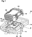
- the figure 1 shows an electrotechnical product 100 according to the invention, which is embodied as a construction spotlight in the illustrated embodiment.
- the electrotechnical product 100 is mechanically and electrically connected to a battery pack 400 for mains-independent power supply.
- the present invention is not limited to site spotlights, but rather to different electrotechnical products 100 such as, for example a charger for a battery pack of a hand tractor or a construction site radio, which can be used with a mains connection or with an in figure 3 illustrated first energy store 400, in particular a battery pack for mains-independent power supply are operated.
- This first energy store 400 is arranged under a tight and closed cover 420 and is therefore not visible in detail.
- the cover 420 is advantageously embodied in such a way that it seals both the battery pack 400 and the connection interface 380 underneath it, and thereby the entire electrotechnical product 100, from external influences such as rainwater and/or dust, whereby the electronic product 100 has an IP (Ingress Protection or International Protection) classification.
- IP Ingress Protection or International Protection
- the electrotechnical product 100 has a housing 120 with a carrying handle 124 and a foldable support foot 128 . Both the support foot 128 and the carrying handle 124 are fastened to the hand-held lighting device 100 so that they can be pivoted about an axis of rotation x in the illustrated embodiment.
- the housing 120 also has a first housing section 122 and a second housing section 126, in the interior of which a light source (not shown), for example a number of light-emitting diodes, can be arranged in a protected manner so that they are protected from environmental influences.
- the first housing section 122 also has a transparent cover 500 through which the light emitted by the lighting means can penetrate. The bulbs are controlled by a controller such. B.
- an electronic control system 170 which includes, for example, a switched-mode power supply or the like other suitable electrical means.
- the lamps can be switched on and off via an electrical switch that is not shown in detail.
- the electrical switch is protected inside the housing 120 and has an in figure 3 recognizable pressure surface 190, which is arranged in the illustrated embodiment on the handle 124, operable.
- the control electronics 170 of the electrotechnical product 100 or of the site spotlight is preferably designed in such a way that the lighting means can be switched in several, for example three, brightness levels. Accordingly, the illuminant of the electrotechnical product 100 can successive key confirmations or by keeping the pressure surface 190 pressed, for example switched on in succession, switched to a higher or lower brightness level and/or switched off. Of course, other switches, for example an additional "brightness switch" in the form of a slider, rotary switch or the like, are also conceivable as an alternative.
- the transparent cover 500 is provided on a front side of the case 120 .
- the support foot 128 is used, among other things, to place the electrotechnical product 100 on a base and is advantageously used to ensure a secure footing.
- the control electronics 170 and the radio module 210 are arranged inside the housing 120, the radio module 210 being designed to receive information from at least one external interface (not shown) and/or to send it to the external interface.
- the control electronics 170 are electrically connected to the lighting means.
- the radio module 210 is connected to the control electronics 170 of the electrotechnical product 100 or alternatively can also be integrated directly into it.
- the radio module 210 can have at least one interface board of its own and advantageously also its own data memory, the interface board being arranged inside the housing 120 in a detachable manner, in particular screwed and/or clamped, or non-detachably.
- both the control electronics 170 and the radio module 210 have plug connectors or mating plug connectors.
- the connectors and the corresponding mating connectors are connected to one another by means of cables.
- the radio module 210 can be plugged or soldered directly onto the control electronics 170 in order to enable a secure connection.
- the radio module 210 sends a radio signal, for example a Bluetooth signal, a WLAN signal or an NFC signal.
- a WLAN module for example an 868 MHz module or a 915 MHz module, or a Bluetooth module can be used as a preferred exemplary embodiment of such a radio module.
- Other types of radio modules can also be used.
- the radio network can be a communication network of any wireless communication standard, such as WLAN (Wireless Local Area Network), Bluetooth, GSM (Global System for Mobile Communications), GPRS (General Packet Radio Service) or UMTS (Universal Mobile Telecommunications System). Furthermore, it is particularly advantageous if the radio module 210 is designed to carry out an evaluation of local time measurements and/or GPS signals for locating the electrotechnical product 100 .
- WLAN Wireless Local Area Network
- GSM Global System for Mobile Communications
- GPRS General Packet Radio Service
- UMTS Universal Mobile Telecommunications System
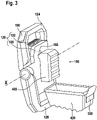
- the electrotechnical product 100 is shown in a bottom view without the IP cover 420 or with the IP cover 420 folded down and the first energy store 400 arranged underneath.
- figure 2 shows the connection interface 380 for contacting a mating interface of the battery pack 400 and a receiving opening 150 for receiving a second energy store 140 and/or, as in FIG figures 4 and 6 shown, of the radio module 210.
- the receiving opening 150 is pot-shaped in the illustrated embodiment. Alternatively, the receiving opening 150 can also have a different shape, for example it can be box-shaped.
- the cup-shaped receiving opening 150 shown has a peripheral side wall 152 and a bottom surface 154 .
- the second energy store 140 is designed as a button cell battery in the illustrated embodiments.
- the receiving opening 150 can be closed by means of a cover 160 .
- the lid 160 is placed in the in figure 2 variant shown by means of a connecting element 162, for example a screw, additionally secured to the housing 120.
- a contact circuit board (not shown in detail) for contacting the second energy store 140 is arranged inside the receiving opening 150, in particular in the area of the bottom surface.
- the electrotechnical product 100 is designed as a construction site radio
- the radio module 210 is designed as a module 300 and is arranged detachably in the receiving opening 150 of the electrotechnical product 100 .
- the module 300 essentially has the second, separate energy store 140 and the radio module 210 .
- a counter-connection element 213 (not shown in detail) of the interface circuit board of the control electronics 170 of the electrotechnical product 100 is arranged within the receiving opening 150 in order to make contact with to allow a non-illustrated connecting element of the radio module 210.
- This contact is advantageously a touch/clamp contact, preferably a SIM card contact, in order to ensure data exchange between the radio module 210 and/or the control electronics 170 of the electrotechnical product 100 .
- the second energy store 140 is detachably arranged in the receiving opening 150 shown on the radio module 210, for example by means of a clamp connection.
- the module 300 is inserted into the receiving opening 150 and is held in the receiving opening 150 with the aid of the cover 160, the module 300 being arranged in the receiving opening 150 with as little play as possible, which in turn avoids rattling noises or the like and accidental release of the module 300 is prevented .
- the module 300 can be clicked into the receiving opening 150 by means of a click connection, for example.
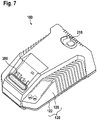
- the electrotechnical product 100 is designed as a charger for a battery pack 400, the in figure 6 illustrated radio module 210 as in figure 4 designed as a module 300 and arranged detachably in the receiving opening 150 of the electrotechnical product 100 .
- module 300 essentially has its own second energy store 140 and radio module 210, with mating connection element 213 (not shown in detail) of the interface circuit board of control electronics 170 of electrotechnical product 100 already being arranged in receiving opening 150 and by means of which the Data exchange between the radio module 210 and/or with the control electronics 170 can be guaranteed.
- the cover 160 can be attached to the housing 120 in a rotary manner, in particular by means of a bayonet lock, with a screw lock also being possible as an alternative. Furthermore, in order to allow safe but simple access to the receiving opening 150 and the second energy store 140 arranged therein and/or the radio module 210, the cover 160 has a slot-shaped recess 164.
- the cover 160 can be opened by means of a coin or a screwdriver, for example, through the slit-shaped recess 164 .
- a further embodiment that is not shown is a hinged cover that is mounted such that it can pivot about a pivot axis and can be releasably locked on the housing 120 on the side opposite the pivot axis by latching, screwing, clamping or bracing. Such a cover 160 can prevent the cover 160 from falling off or being lost.
- the cover 160 can also be designed in such a way that it follows a contour of the housing 120 and is flush with it. Accordingly, the cover 160 can be made of different plastic materials such as PA6, PA6.6, PC (polycarbonate), ABS (acrylonitrile butadiene styrene copolymer) or of a material mix of different plastics and/or reinforced with glass fibers, it being advantageous if if the cover 160 has the same material as the housing 120 of the electrical product 100.
- plastic materials such as PA6, PA6.6, PC (polycarbonate), ABS (acrylonitrile butadiene styrene copolymer) or of a material mix of different plastics and/or reinforced with glass fibers, it being advantageous if if the cover 160 has the same material as the housing 120 of the electrical product 100.
- an alternative embodiment of an electrical product 100 with radio module 210 is shown in each case.
- the radio module 210 is integrated within the housing 120 and cannot be removed or inserted via a separate cover, nor is it connected to the control electronics of the electrotechnical product 100 via a separate interface board.
- Construction site radios often have an additional energy supply, so-called buffer batteries, which are used, for example, to show the time on a display even when there is no power connection or first energy store for the power supply. Accordingly, it is conceivable that in the case of an electrical product 100 which has such a further energy store, this could take over the function of the second energy store.
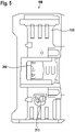
- FIG 5 an alternative arrangement of the radio module 210 on a construction site radio as an electrical product 100 is shown.
- the radio module 210 is within the housing 120 of the electrical product 100 adjacent to the Battery pack interface 380 arranged integrated and has no separate access from the outside.
- the radio module 210 is electrically connected to the first energy store 400, such as the battery pack or the external power supply, and/or to the second energy store 140.
- the radio module 210 is supplied with energy via the first energy store 400, whereas in every other case the radio module 210 is supplied via the second Energy store 140 is supplied with energy, so that an energy supply to the radio module 210 is guaranteed at all times.
- the second energy store 140 is also a rechargeable energy store 140 and if the first energy store 400 is present and has sufficient energy, it is charged with energy via the first energy store 400 .
- a rechargeable second energy store 140 it is also possible for this to be permanently integrated within the housing 120 (not shown).
- the radio module 210 is connected to the control electronics 170 of the electrotechnical product 100 in a wireless or wired manner, for example by means of plug connectors or lines.
- the connection can be detachable using a plug connector or permanently as a soldered connection.
- the radio module 210 can have its own interface circuit board 213 or, in an alternative variant that is not shown, can be integrated directly into the control electronics 170 of the electrotechnical product 100 .
- the radio module 210 can be connected to the interface circuit board 213 in a detachable manner, for example clamped or plugged in, or firmly, for example soldered or glued.
Landscapes
- Engineering & Computer Science (AREA)
- Mechanical Engineering (AREA)
- Charge And Discharge Circuits For Batteries Or The Like (AREA)
- Casings For Electric Apparatus (AREA)
- Battery Mounting, Suspending (AREA)
Description
- Die vorliegende Erfindung betrifft ein elektrotechnisches Erzeugnis nach Anspruch 1.
- Elektrotechnische Erzeugnisse wie beispielsweise ein Ladegerät für ein Akkupack einer Handwerkzeugmaschine, ein Baustellenradio oder ein Baustrahler sind grundsätzlich bekannt und werden in der Regel über einen Netzanschluss mit Strom versorgt. Alternativ ermöglichen Akkugeräte eine hohe Flexibilität beim Arbeiten, da sie insbesondere unabhängig von Netzstrom sind. Auf diese Weise können beispielsweise auch Außenarbeiten bequem durchgeführt werden, so dass bei einem Betrieb des elektrotechnischen Erzeugnisses vielfach vorgesehen ist Akkupacks einzusetzen.
- Derartige Akkupacks sind grundsätzlich bekannt und weisen wiederaufladbare Akkumulatoren, in der Regel eine Mehrzahl von in Parallel- und/oder Reihenschaltung verbundener Akkuzellen auf. Im Zuge dieser Anmeldung ist unter einem Akkupack somit ein vorzugsweise aus mehreren elektrisch zusammengeschalteten Akkuzellen bestehenden Akkupack zu verstehen, der elektrische Energie speichern kann und für den Betrieb eines elektrotechnischen Erzeugnisses und/oder einer Handwerkzeugmaschine die Energie liefert. Es können beispielsweise drei in Reihe geschaltete, zylinderförmige Li-Ionen-Zellen mit z.B. je 3,6 V zu einer Gesamtspannung von 10,8 V vorgesehen sein.
- Aus dem Stand der Technik sind beispielsweise Handleuchtgeräte oder Ladegeräte für Akkupacks bekannt, die ein Überwachungsmodul aufweisen, welches beispielsweise den Ladestatus des Akkupacks überwacht. Dabei erweist es sich als nachteilig, dass derartige Überwachungsmodule nur begrenzt von Nutzen sind, da die überwachten Daten nur vor Ort angezeigt werden. Beispiele werden in der
US2014/240125A1 undUS2013/277078A1 offenbart. - Der vorliegenden Erfindung liegt die Aufgabe zugrunde, die oben genannten Nachteile zu verbessern und ein elektrotechnisches Erzeugnis, insbesondere ein elektrotechnisches Erzeugnis ohne Antriebsmotor der eingangs genannten Art bereitzustellen, bei dem eine Übermittlung von Daten, Parametern oder dergleichen von und an eine externe Schnittstelle mit einfachem konstruktivem Aufwand auch über größere Entfernungen sicher ermöglicht wird und gleichzeitig eine Anpassung an andere Gegebenheiten hinsichtlich einer entsprechenden Verbindung zwischen dem Elektrotechnischen Erzeugnis und einer externen Schnittstelle schnell und leicht zur Verfügung gestellt werden kann. Ferner ist es Aufgabe der Erfindung ein elektrotechnisches Erzeugnis zu offenbaren, bei dem unter geringem Aufwand eine Kommunikationsschnittstelle für ein elektrotechnisches Erzeugnis zur Verfügung gestellt, eingebaut und ausgetauscht werden kann, wobei der Einbau- und/oder der Austauschprozess möglichst einfach und kostengünstig durchführbar sein sollen.
- Diese Aufgabe wird durch ein Elektrotechnisches Erzeugnis, insbesondere ein elektrotechnisches Erzeugnis ohne Antriebsmotor gemäß Anspruch 1 gelöst. Vorteilhafte Ausgestaltungen, Varianten und Weiterbildungen der Erfindung sind den Unteransprüchen zu entnehmen.
- Gemäß der Erfindung ist ein elektrotechnisches Erzeugnis, insbesondere ein elektrotechnisches Erzeugnis ohne Antriebsmotor mit einem Funkmodul, wobei das Funkmodul dazu ausgelegt ist, Informationen von zumindest einer externen Schnittstelle zu empfangen und/oder an zumindest eine externe Schnittstelle zu senden. Erfindungsgemäß ist vorgesehen, dass das Funkmodul in einem Gehäuse des elektrotechnischen Erzeugnisses angeordnet ist, wobei erfindungsgemäß vorgesehen ist, dass das Funkmodul entweder dauerhaft, als fest integriertes oder als lösbares und somit separat entnehmbares Funkmodul in dem Gehäuse des elektrotechnischen Erzeugnisses angeordnet sein kann.
- Bei dem Funkmodul handelt es sich hierbei um eine elektrotechnische Komponente, die zur Herstellung einer Kommunikationsverbindung über ein Funknetz in verschiedensten Bereichen eingesetzt wird. So werden Funkmodule beispielsweise bereits für Anwendungen im so genannten Maschine-zu-Maschine (Machine-to-Machine, M2M) Umfeld verwendet, wie zum Beispiel im Bereich der Industrieautomatisierung, in Kraftfahrzeugen zur Unterstützung von Anwendungen im Bereich der Telematik oder auch zur Fernabfrage von Verbrauchszählern wie beispielsweise Strom-, Gas- oder Wasserzählern. Generell wird durch die Verwendung eines Funkmoduls ermöglicht, eine drahtlose Datenübertragung über ein Funknetz vorzunehmen, wodurch insbesondere Aufwände für eine anderenfalls erforderliche Verkabelung vermieden werden. Auf diese Weise kann eine Übermittlung von Daten, Parametern oder dergleichen von und an eine externe Schnittstelle mit einfachem konstruktivem Aufwand sicher ermöglicht werden.
- Wie in Anspruch 1 dargestellt, wird das elektrotechnische Erzeugnis über einen ersten Energiespeicher, insbesondere über einen Akkupack eines Handwerkzeugs oder über eine Netzstromanbindung, mit Energie versorgt. Vorteilhafterweise handelt es sich bei diesem ersten Energiespeicher um einen austauschbaren, am Gehäuse angeordneten Schiebeakkupack oder Steckakkupack. Um das Funkmodul in einfacher Weise mit ausreichender Leistung versorgen zu können, ist gemäß einer bevorzugten Weiterbildung der Erfindung vorgesehen, dass das Funkmodul über die Stromversorgung des elektrotechnischen Erzeugnisses mit Energie versorgt wird. Dies kann beispielsweise mittels einer lösbaren Anbindung des Funkmoduls an eine Steuerelektronik des elektrotechnischen Erzeugnisses gewährleistet werden, wodurch einerseits die Stromversorgung des Funkmoduls über die Stromversorgung des elektrotechnischen Erzeugnissen ermöglicht und andererseits der Batteriestatus des ersten Energiespeichers und/oder die daraus resultierende Restlaufzeit des elektrotechnischen Erzeugnisses an eine externe Schnittstelle übermittelt werden kann.
- Alternativ ist denkbar, dass das Funkmodul einen eigenen zweiten Energiespeicher, der innerhalb des elektrotechnischen Erzeugnisses angeordnet ist, aufweist. Entsprechend ist in einer besonders bevorzugten Ausführungsform vorgesehen, dass das Funkmodul elektrisch mit dem ersten Energiespeicher und/oder mit dem zweiten Energiespeicher verbunden ist. Ferner ist vorgesehen, dass das Funkmodul in dem Fall, in dem der erste Energiespeicher vorhanden ist und über ausreichend Energie verfügt, über den ersten Energiespeicher mit Energie versorgt wird; und in jedem anderen Fall über den zweiten Energiespeicher versorgt wird. Auf diese Weise kann jederzeit einer Energieversorgung des Funkmoduls gewährleistet werden.
- Vorteilhafterweise ist auch der zweite Energiespeicher wiederaufladbar, wobei der zweite Energiespeicher in dem Fall, in dem der erste Energiespeicher vorhanden ist und über ausreichend Energie verfügt, über den ersten Energiespeicher mit Energie aufgeladen wird. Mittels des Funkmoduls ist eine Übermittlung des Batteriestatus des zweiten Energiespeichers an eine externe Schnittstelle möglich, so dass ein Nutzer des elektrotechnischen Erzeugnisses entsprechend rechtzeitig reagieren kann.
- Wie in Anspruch 1 dargestellt, weist das Gehäuse des elektrotechnischen Erzeugnisses eine Aufnahmeöffnung auf, in der das Funkmodul und/oder der zweite Energiespeicher herausnehmbar aufgenommen werden können. Auf diese Weise können das Funkmodul und/oder der zweite Energiespeicher lösbar an dem elektrotechnischen Erzeugnis angebracht werden, wobei die Aufnahmeöffnung einen einfachen und kostengünstigen Austausch des im Gehäuse des elektrotechnischen Erzeugnisses angeordneten Funkmoduls und/oder des zweiten Energiespeichers ermöglicht.
- Vorteilhafterweise bildet das Gehäuse die Aufnahmeöffnung unmittelbar in der Gehäusewand des elektrotechnischen Erzeugnisses aus, wobei die Aufnahmeöffnung topfförmig oder kastenförmig mit einer Bodenfläche ausgeführt sein kann. Wie in Anspruch 1 dargestellt, ist die Aufnahmeöffnung durch einen Deckel verschließbar, wobei der Deckel vorzugsweise der Kontur der Gehäusewand folgt und bündig mit dieser abschließt. Der Deckel kann aus unterschiedlichen Kunststoffmaterialien wie beispielsweise PA6, PA6.6, PC (Polycarbonat), ABS (Acrylnitril-Butadien-Styrol-Copolymerisat) oder aus einem Materialmix verschiedener Kunststoffe und/oder glasfaserverstärkt ausgeführt sein. Vorzugsweise weist der Deckel das gleiche Material auf, wie das Gehäuse des elektrotechnischen Erzeugnisses.
- Um einen sicheren, aber einfachen Zugang zur Aufnahmeöffnung und dem darin angeordneten zweiten Energiespeicher und/oder dem Funkmodul zu ermöglichen, ist es von Vorteil, wenn der Deckel rotatorisch, insbesondere über einen Schraub- oder einen Bajonettverschluss lösbar verriegelt wird. Eine weitere Ausführungsform ist ein um eine Schwenkachse verschwenkbar gelagerter Deckel, welcher an einer der Schwenkachse gegenüberliegenden Seite des Deckels durch Verrasten, Verschrauben, Verklemmen oder Verspannen an dem Gehäuse lösbar arretiert werden kann. Auf diese Weise kann wirksam einem möglichen Abfallen des Deckels vom Gehäuse oder einem Verlieren des Deckels entgegengewirkt werden. Der Deckel kann ferner eine schlitzförmige Vertiefung aufweisen, wodurch ein einfaches Öffnen des Deckels mittels einer Münze oder eines Schraubendrehers erfolgen kann. Der Bajonettverschluss lässt sich leicht betätigen und gewährleistet dennoch einen sicheren Verschluss der Aufnahmeöffnung. Zusätzlich oder alternativ kann der Deckel auch mittels wenigstens eines Verbindungselements, insbesondere mittels wenigstens einer Schraube am Gehäuse befestigt werden.
- Ferner ist es von Vorteil, wenn der zweite Energiespeicher mittels einer Federbeaufschlagung in der Aufnahmeöffnung angeordnet ist, wodurch eine sichere Kontaktierung mit dem Funkmodul und/oder mit einer Kontaktplatine gewährleistet werden kann. Grundsätzlich kann vorgesehen sein, dass das entsprechende Federelement zwischen dem Deckel und dem zweiten Energiespeicher oder zwischen der Bodenfläche der Aufnahmeöffnung und dem zweiten Energiespeicher angeordnet ist, um den Energiespeicher bei geschlossenem Deckel gegen die innerhalb der Aufnahmeöffnung vorgesehenen Kontaktanschlüsse zu drücken. In einer bevorzugten Ausführungsform ist der zweite Energiespeicher austauschbar und/oder als eine Art Knopfbatterie ausgebildet. Vorteilhafterweise wäre ein derartiger zweiter Energiespeicher als eine Art Knopfbatterie ausgebildet.
- Erfindungsgemäß kann diese durch Öffnen des Deckels erreicht werden, so dass ein Benutzer den zweiten Energiespeicher durch die Öffnung hindurch aus der Aufnahmeöffnung entnehmen und durch einen neuen, aufgeladenen Energiespeicher ersetzen kann. Durch erneutes Verschließen des Deckels ist der Energiespeicher sicher innerhalb der Aufnahmeöffnung aufbewahrt. Ein Austausch des gesamten Funkmoduls kann auf diese Weise umgangen und ein dauerhafter Betrieb auf einfache Art und Weise gewährleistet werden. Alternativ ist denkbar, dass der zweite wieder aufladbare Energiespeicher fest innerhalb des Gehäuses integriert ist, wobei in diesem Fall der zweite Energiespeicher elektrisch mit der Energieversorgung des elektrotechnischen Erzeugnisses verbunden ist, so dass der zweite Energiespeicher durch die von dem Stromnetz oder dem Akkupack des elektrotechnischen Erzeugnisses zur Verfügung gestellten Energie wieder aufgeladen werden kann. Vorteilhafterweise ist in diesem Fall eine Steuerelektronik innerhalb des elektrotechnischen Erzeugnisses vorgesehen, die in Abhängigkeit von der Energieversorgung des elektrotechnischen Erzeugnisses den zweiten Energiespeicher auflädt und/oder lediglich die Energieversorgung des Funkmoduls über die Energieversorgung des elektrotechnischen Erzeugnisses ermöglicht, wodurch ein dauerhafter Betrieb auf einfache Art und Weise gewährleistet werden kann.
- Vorteilhafterweise ist das Funkmodul mit einer Steuerelektronik des elektrotechnischen Erzeugnisses verbunden oder in diese integriert, so dass beispielsweise die Schaltung des Funkmoduls auf der Steuerelektronik des elektrotechnischen Erzeugnisses untergebracht werden kann. Alternativ kann das Funkmodul auch eine eigene Steuerelektronik aufweisen.
- Im Falle eines entnehmbaren Funkmoduls weist das Funkmodul wenigstens ein Verbindungselement, beispielsweise eine Simkartenkontaktierung und/oder Messerkontakte zur Kontaktierung des Akkupacks, zur Kontaktierung wenigstens ein Gegenverbindungselement der Steuerelektronik des elektrotechnischen Erzeugnisses auf. Entsprechend ist vorgesehen, dass im Falle eines entnehmbaren Funkmoduls eine separate Schnittstelle im elektrotechnischen Erzeugnis angeordnet ist; wobei vorteilhafterweise diese separate Schnittstelle unmittelbar auf der Steuerelektronik/Steuerelektronik des elektrotechnischen Erzeugnisses angeordnet ist.
- Alternativ kann insbesondere bei einem dauerhaft eingebauten Funkmodul vorgesehen sein, dass das Funkmodul wenigstens eine eigene Schnittstellenplatine zum drahtgebundenen oder drahtlosen Datenaustausch mit der Steuerelektronik des elektrotechnischen Erzeugnisses aufweist, wobei die Schnittstellenplatine des Funkmoduls wenigstens eine, vorzugsweise zwei Verbindungselemente, insbesondere Steckverbindungen aufweist, wobei wenigstens ein Verbindungselement den Datenaustausch und/oder die Energieversorgung mit oder durch die Steuerelektronik des elektrotechnischen Erzeugnisses gewährleistet und/oder ein weiteres Verbindungselement leitungsgebunden eine Kontaktplatine des zweiten Energiespeichers kontaktiert. Erfindungsgemäß ist für ein derartiges fest eingebautes Funkmodul vorgesehen, dass sowohl die Steuerelektronik des elektrotechnischen Erzeugnisses als auch das Funkmodul Steckverbinder bzw. Gegensteckverbinder aufweisen, um den Datenaustausch zwischen der Schnittstellenplatine des Funkmoduls, bzw. zwischen der Steuerelektronik des Funkmoduls und/oder der Steuerelektronik des elektrotechnischen Erzeugnisses zu gewährleisten. Die Steckverbinder und die entsprechenden Gegensteckverbinder werden wiederum mittels Leitungen miteinander verbunden. Alternativ kann das Funkmodul unmittelbar mit der Steuerelektronik des elektrotechnischen Erzeugnisses lösbar, beispielsweise gesteckt, oder fest, beispielsweise gelötet, verbunden werden, um eine sichere Anbindung und Übertragung zu ermöglichen.
- Erfindungsgemäß ist vorgesehen, dass die Schnittstellenplatine mittels einer Steckverbindung und/oder mittels Federkontakten und/oder leitungsgebunden verlötet und/oder steckbar mit der Steuerelektronik des elektrotechnischen Erzeugnisses verbunden insbesondere verschraubt und/oder verklemmt, oder unlösbar innerhalb des Gehäuses angeordnet ist. Vorteilhafterweise wird das Funkmodul zum Schutz vor äußeren Einflüssen zusammen mit der Steuerelektronik des elektrotechnischen Erzeugnisses oder separat innerhalb des Gehäuses eingegossen. Ferner kann das Funkmodul innerhalb des Gehäuses vorinstalliert sein, nachgerüstet oder ausgetauscht werden. Dabei ist es besonders vorteilhaft, wenn das Funkmodul unmittelbar innerhalb der Aufnahmeöffnung austauschbar angeordnet ist.
- In einer bevorzugten Ausführungsform der erfindungsgemäßen Anordnung empfängt und/oder sendet das Funkmodul ein Funksignal basierend auf elektromagnetischen Wellen, beispielsweise ein Bluetooth-Signal, insbesondere ein Bluetooth Low Energy Signal, ein WLAN-Signal oder ein NFC-Signal. Als bevorzugtes Ausführungsbeispiel eines solchen Funkmoduls kann beispielsweise ein WLAN-Modul, beispielsweise ein 868-MHz-Modul, ein 915-MHz-Modul oder auch ein Bluetooth-Module verwendet werden. Weitere Arten von Funkmodulen sind ebenfalls verwendbar. Bei dem Funknetz kann es sich dabei um ein Kommunikationsnetz eines beliebigen drahtlosen Kommunikationsstandards handeln, wie beispielsweise WLAN (Wireless Local Area Network), Bluetooth, GSM (Global System for Mobile Communications), GPRS (General Packet Radio Service) oder UMTS (Universal Mobile Telecommunications System). Darüber hinaus finden insbesondere im Bereich der Industrieautomatisierung zunehmend speziell an die entsprechenden Anforderungen angepasste drahtlose Kommunikationsnetze mit vergleichsweise kurzer Reichweite Anwendung, die auch als "Wireless Personal Area Network (WPAN)" bezeichnet werden. Als Beispiele hierfür seien Funknetze nach einem der Standards IEEE 802.15.4 oder WirelessHART genannt.
- Vorteilhafterweise sendet ein aktives Funkmodul alle acht Sekunden ein Signal aus. Alternativ und in Abhängigkeit von der Energieversorgung kann das Signal auch in kürzeren oder auch in längeren Abständen ausgesendet werden. Insbesondere bei einer Energieversorgung durch den zweiten Energiespeicher kann das Funksignal beispielsweise alle zehn, 20 oder 30 Sekunden ausgesendet werden, wohingegen bei einer Energieversorgung durch den ersten Energiespeicher das Funkmodul beispielsweise alle vier oder sogar jede Sekunde ein Signal aussendet. Das entsprechende Funkmodul kann insbesondere seriell mit der Steuerelektronik, einer Messeinrichtung zur Messung von diversen elektrotechnischen Variablen oder dergleichen verbunden sein. Solche Variablen sind beispielsweise Angaben über den An/Aus Status, über die Dauer des An/Aus Status, die Leuchtintensität bei Leuchten, die Lautstärke bei Radios der Ladezustand des am Erzeugnis befestigten Akkupacks, ein GPS Signal über den aktuellen Standort und/oder über den Standortverlauf usw..
- Vorteilhafterweise werden über die externe Schnittstelle und das Funkmodul Steuerungsbefehle, wie beispielsweise das Einschalten und/oder das Ausschalten, an die Steuerungselektronik des elektrotechnischen Erzeugnisses übermittelt. Ferner kann eine definierte Zeit, in der ein derartiger Schaltvorgang, wie beispielsweise ein, aus und/oder dimmen, stattfinden soll und/oder eine Zeitdauer für den ein bestimmter Schaltzustand wie beispielsweise ein, aus und/oder gedimmt, gelten soll festgelegt und über das Funkmodul an die Steuerelektronik des elektrotechnischen Erzeugnisses übermittelt werden. Weiterhin ist es möglich, dass das elektrotechnische Erzeugnis über das Funkmodul von einem zuvor definierten Nutzer gesperrt und ein Zugriff durch einen unberechtigten Nutzer verhindert werden kann. Entsprechend ist es auch möglich, dass der Sperrstatus durch einen Nutzer abgefragt werden kann. Ferner kann erfindungsgemäß vorgesehen sein, dass das Funkmodul dazu ausgelegt ist, eine Auswertung von Ortszeitmessungen und/oder von GPS-Signalen zur Ortung des elektrotechnischen Erzeugnisses durchzuführen.
- In einer besonders vorteilhaften Ausführungsform bildet das Funkmodul mit dem zweiten Energiespeicher ein eigenständiges Modul aus, welches separat und lösbar innerhalb des Gehäuses des elektrotechnischen Erzeugnisses einbringbar ist, wobei das Modul beispielsweise durch eine Schraubverbindung oder durch andere Verbindungselemente lösbar an dem Gehäuse befestigt wird. Auf diese Weise ist das Funkmodul besonders kompakt ausgebildet und lässt sich schnell und einfach montieren, austauschen und/oder nachrüsten, so dass auch ein Austausch und/oder eine Reparatur schnell, einfach und kostengünstig erfolgen kann.
- Die erfindungsgemäße Anordnung ist für beliebige Arten von elektrotechnischen Erzeugnissen einsetzbar. In einer besonders bevorzugten Ausführungsform ist das elektrotechnische Erzeugnis als tragbares elektrotechnisches Erzeugnis, als Handleuchtgerät, insbesondere als Baustrahler, als Baustellenradio oder als Ladegerät für einen Akkupack einer Handwerkzeugmaschine ausgestaltet wobei das Funkmodul und damit das elektrotechnische Erzeugnis, die Art des elektrotechnischen Erzeugnisses und/oder die darin verwendeten Bestandteile, wie Akkupackart, Art der eingebauten Leuchtmittel oder dergleichen anhand eines ausgesendeten Codes identifiziert werden kann.
- Das erfindungsgemäße elektrotechnische Erzeugnis kann auch in einem System vorgesehen sein, wie in Anspruch 17 dargestellt. Dementsprechend bildet auch ein elektrotechnisches Erzeugnis zusammen mit einer externen Einheit, die dazu ausgelegt ist, Informationen vom Funkmodul zu empfangen und/oder an das Funkmodul zu senden, einen weiteren Gegenstand der Erfindung. Erfindungsgemäß kann vorgesehen sein, dass die externe Einheit ein Smartphone, eine elektrotechnische Datenverarbeitungsanlage, ein Tablet, ein zweites elektrotechnisches Erzeugnis oder ein Elektrowerkzeug ist.
- Durch dieses System wird mit einfachem konstruktivem Aufwand und über größere Entfernungen ein sicherer Austausch von Daten, Parametern oder dergleichen zwischen dem elektrotechnischen Erzeugnis und der externen Einheit ermöglicht, wodurch eine Kontrolle der Betriebsmodi und/oder ein Wiederauffinden des elektrotechnischen Erzeugnisses erleichtert werden kann. Ferner können mittels einem erfindungsgemäßen elektrotechnischen Erzeugnis bzw. in einem erfindungsgemäßen System mehrere elektrotechnische Erzeugnisse gruppiert und mittels der externen Schnittstelle und dem jeweiligen Funkmodul gemeinsam bedient werden. Dabei ist es besonders vorteilhaft, dass die elektrotechnischen Erzeugnisse mittels der externen Schnittstelle und/oder über ihre Funkmodule direkt miteinander kommunizieren können.
- Weitere Merkmale, Anwendungsmöglichkeiten, Vorteile und Ausgestaltungen der Erfindung ergeben sich aus der nachfolgenden Beschreibung der Ausführungsbeispiele der Erfindung, welche in den Figuren dargestellt sind. Die Beschreibung, die zugehörigen Figuren sowie die Ansprüche enthalten zahlreiche Merkmale in Kombination.
- Die Erfindung wird im Folgenden anhand von bevorzugten Ausführungsbeispielen näher erläutert. Die Zeichnungen sind schematisch und zeigen:
- Fig. 1
- eine perspektivische Draufsicht einer ersten Ausführungsvariante eines erfindungsgemäßen elektrotechnischen Erzeugnisses mit einem eingesetzten Funkmodul;
- Fig. 2
- eine perspektivische Unteransicht des erfindungsgemäßen elektrotechnischen Erzeugnisses aus
Figur 1 mit einem zweiten Energiespeicher ohne Akkupack; - Fig. 3
- das erfindungsgemäße elektrotechnische Erzeugnis aus
Figur 1 mit einem eingesetzten Akkupack; - Fig. 4
- eine perspektivische Draufsicht einer zweiten Ausführungsvariante eines erfindungsgemäßen elektrotechnischen Erzeugnisses mit einem Funkmodul;
- Fig. 5
- eine Unteransicht einer dritten Ausführungsvariante eines erfindungsgemäßen elektrotechnischen Erzeugnisses mit integriertem Funkmodul;
- Fig. 6
- eine perspektivische Draufsicht einer vierten Ausführungsvariante eines erfindungsgemäßen elektrotechnischen Erzeugnisses mit einem Funkmodul; und
- Fig. 7
- das erfindungsgemäße elektrotechnische Erzeugnis aus
Figur 6 mit integriertem Funkmodul. - Die
Figur 1 zeigt ein erfindungsgemäßes elektrotechnisches Erzeugnis 100, welches in der dargestellten Ausführungsform als Baustrahler ausgebildet ist. Gemäß der dargestellten Ausführungsform ist das elektrotechnische Erzeugnis 100 zur netzunabhängigen Stromversorgung mechanisch und elektrisch mit einem Akkupack 400 verbunden. Grundsätzlich wird darauf hingewiesen, dass die vorliegende Erfindung nicht auf Baustrahler beschränkt ist, sondern vielmehr bei unterschiedlichen elektrotechnischen Erzeugnissen 100 wie beispielsweise einem Ladegerät für einen Akkupack einer Handwerkzugmaschine oder einem Baustellenradio, Anwendung finden kann, welche mit einem Netzanschluss oder mit einem inFigur 3 dargestellten ersten Energiespeicher 400, insbesondere einem Akkupack zur netzunabhängigen Stromversorgung betrieben werden. InFigur 1 ist dieser erste Energiespeicher 400 unter einem dichten und geschlossen ausgebildeten Deckel 420 angeordnet und somit im Detail nicht zu erkennen. Der Deckel 420 ist vorteilhafterweise derart ausgeführt dass er sowohl den Akkupack 400 als auch die darunter liegende Anschlussschnittstelle 380 und dadurch das gesamte elektrotechnische Erzeugnis 100 gegenüber Außeneinflüssen wie beispielsweise Regenwasser und/oder Staub abdichtet, wodurch das elektronische Erzeugnis 100 eine IP (Ingress Protection bzw. International Protection) Klassifizierung erhält. - Das elektrotechnische Erzeugnis 100 weist ein Gehäuse 120 mit einem Tragegriff 124 und einen klappbaren Stützfuss 128 auf. Sowohl der Stützfuss 128 als auch der Tragegriff 124 sind in der dargestellten Ausführungsform um eine Drehachse x schwenkbar an das Handleuchtgerät 100 befestigt. Das Gehäuse 120 weist zudem einen ersten Gehäuseabschnitt 122 und einen zweiten Gehäuseabschnitt 126 auf, in dessen Innenraum ein nicht dargestelltes Leuchtmittel, zum Beispiel eine Anzahl von Leuchtdioden, geschützt angeordnet werden kann, so dass sie vor Umwelteinflüssen geschützt sind. Der erste Gehäuseabschnitt 122 weist ferner eine transparente Abdeckung 500 auf, die von dem ausstrahlenden Licht der Leuchtmittel durchdrungen werden kann. Die Leuchtmittel werden von einer Steuerung, z. B. einer Steuerelektronik 170, angesteuert, die beispielsweise ein Schaltnetzteil oder dergleichen andere geeignete elektrische Mittel umfasst. Über einen nicht im Detail dargestellten elektrischen Schalter können die Leuchtmittel ein- und ausgeschaltet werden. Der elektrische Schalter ist im Innern des Gehäuses 120 geschützt angeordnet und über eine in
Figur 3 erkennbare Druckfläche 190, die in der dargestellten Ausführungsform am Handgriff 124 angeordnet ist, betätigbar. - Bevorzugt ist die Steuerelektronik 170 des elektrotechnischen Erzeugnisses 100 bzw. des Baustrahlers so ausgestaltet, dass die Leuchtmittel in mehreren, beispielsweise drei Helligkeitsstufen, schaltbar sind. Entsprechend kann das Leuchtmittel des elektrotechnischen Erzeugnisses 100 durch aufeinanderfolgende Tastbestätigungen oder mittels gedrückt halten der Druckfläche 190, beispielsweise nacheinander eingeschaltet, auf eine höhere oder niedrigere Helligkeitsstufe geschaltet und/oder ausgeschaltet werden. Selbstverständlich sind alternativ auch andere Schalter, beispielsweise ein zusätzlicher "Helligkeitsschalter" in Form eines Schiebereglers, Drehschalters oder dergleichen denkbar. Die transparente Abdeckung 500 ist an einer Vorderseite des Gehäuses 120 vorgesehen. Der Stützfuss 128 dient unter anderem zum Abstellen des elektrotechnischen Erzeugnisses 100 auf einem Untergrund und dient dabei vorteilhaft dazu, sicheren Stand zu gewährleisten. Innerhalb des Gehäuses 120 ist zum einen die Steuerelektronik 170 und zum anderen das Funkmodul 210 angeordnet, wobei das Funkmodul 210 dazu ausgelegt ist, Informationen von zumindest einer externen, nicht dargestellten Schnittstelle zu empfangen und/oder an die externe Schnittstelle zu senden. Die Steuerelektronik 170 ist elektrisch mit den Leuchtmitteln verbunden. Das Funkmodul 210 ist mit der Steuerelektronik 170 des elektrotechnischen Erzeugnisses 100 verbunden oder kann alternativ auch unmittelbar in diese integriert sein. Ferner kann das Funkmodul 210 wenigstens eine eigene Schnittstellenplatine und vorteilhafterweise auch einen eigenen Datenspeicher aufweisen, wobei die Schnittstellenplatine innerhalb des Gehäuses 120 lösbar, insbesondere verschraubt und/oder verklemmt, oder unlösbar angeordnet ist.
- Um die Steuerelektronik 170 mit dem Funkmodul 210 zu verbinden, weisen sowohl die Steuerelektronik 170 als auch das Funkmodul 210 Steckverbinder bzw. Gegensteckverbinder auf. Die Steckverbinder und die entsprechenden Gegensteckverbinder werden mittels Leitungen miteinander verbunden. Alternativ kann das Funkmodul 210 unmittelbar auf die Steuerelektronik 170 aufgesteckt oder gelötet werden, um eine sichere Anbindung zu ermöglichen. Das Funkmodul 210 sendet ein Funksignal, beispielsweise ein Bluetooth-Signal, ein WLAN-Signal oder ein NFC-Signal. Als bevorzugtes Ausführungsbeispiel eines solchen Funkmoduls kann beispielsweise ein WLAN-Modul, beispielsweise ein 868-MHz-Modul oder ein 915-MHz-Modul, oder auch ein Bluetooth-Modul verwendet werden. Weitere Arten von Funkmodulen sind ebenfalls verwendbar. Bei dem Funknetz kann es sich dabei um ein Kommunikationsnetz eines beliebigen drahtlosen Kommunikationsstandards handeln, wie beispielsweise WLAN (Wireless Local Area Network), Bluetooth, GSM (Global System for Mobile Communications), GPRS (General Packet Radio Service) oder UMTS (Universal Mobile Telecommunications System). Ferner ist es besonders vorteilhaft, wenn das Funkmodul 210 dazu ausgelegt ist, eine Auswertung, von Ortszeitmessungen, und/oder von GPS-Signalen zur Ortung des elektrotechnischen Erzeugnisses 100 durchzuführen.
- In den
Figuren 2 und3 ist das elektrotechnische Erzeugnis 100 in einer Unteransicht ohne den IP-Deckel 420 bzw. mit abgeklappten IP-Deckel 420 und den darunter angeordneten ersten Energiespeicher 400 dargestellt.Figur 2 zeigt die Anschlussschnittstelle 380 zur Kontaktierung einer Gegenschnittstelle des Akkupacks 400 sowie eine Aufnahmeöffnung 150 zur Aufnahme eines zweiten Energiespeichers 140 und/oder, wie inFiguren 4 und6 dargestellt, des Funkmoduls 210. Die Aufnahmeöffnung 150 ist in der dargestellten Ausführungsform topfförmig ausgeführt. Alternativ kann die Aufnahmeöffnung 150 auch eine andere Form haben, beispielsweise kastenförmig sein. Die dargestellte topfenförmige Aufnahmeöffnung 150 weist eine umlaufende Seitenwandung 152 und eine Bodenfläche 154 auf. Der zweite Energiespeicher 140 ist in den dargestellten Ausführungsformen als Knopfzellenbatterie ausgebildet. Die Aufnahmeöffnung 150 ist mittels eines Deckels 160 verschließbar. Der Deckel 160 wird in der inFigur 2 dargestellten Variante mittels eines Verbindungselementes 162, beispielsweise einer Schraube, zusätzlich am Gehäuse 120 gesichert. Insbesondere bei dem dargestellten dauerhaft eingebauten Funkmodul 210 kann vorgesehen sein, dass innerhalb der Aufnahmeöffnung 150, insbesondere im Bereich der Bodenfläche eine nicht im Detail dargestellte Kontaktplatine zur Kontaktierung des zweiten Energiespeichers 140 angeordnet ist. - In der
Figur 4 und5 ist das elektrotechnische Erzeugnis 100 als Baustellenradio ausgebildet, wobei inFigur 4 das Funkmodul 210 als Modul 300 ausgebildet und lösbar in der Aufnahmeöffnung 150 des elektrotechnischen Erzeugnisses 100 angeordnet ist. Das Modul 300 weist in der dargestellten Ausführungsvariante im Wesentlichen den zweiten, eigenen Energiespeicher 140 und das Funkmodul 210 auf. Innerhalb der Aufnahmeöffnung 150 ist ein nicht im Detail dargestelltes Gegenverbindungselement 213 der Schnittstellenplatine der Steuerelektronik 170 des elektrotechnischen Erzeugnisses 100 angeordnet, um eine Kontaktierung mit einem nicht dargestellten Verbindungselement des Funkmoduls 210 zu ermöglichen. Vorteilhafterweise handelt es sich bei dieser Kontaktierung um einen Berührungs-/Klemmkontakt, vorzugsweise um eine Simkartenkontaktierung, um den Datenaustausch zwischen dem Funkmodul 210 und/oder der Steuerelektronik 170 des elektrotechnischen Erzeugnisses 100 zu gewährleisten. Der zweite Energiespeicher 140 ist in der dargestellten Aufnahmeöffnung 150 lösbar auf dem Funkmodul 210 beispielsweise mittels einer Klemmverbindung angeordnet. - Das Modul 300 ist in die Aufnahmeöffnung 150 eingelegt und wird mit Hilfe des Deckels 160 in der Aufnahmeöffnung 150 gehalten, wobei das Modul 300 weitestgehend spielfrei in der Aufnahmeöffnung 150 angeordnet ist, wodurch wiederum Klappergeräusche oder dergleichen vermieden und ein versehentliches Lösen des Moduls 300 verhindert wird. Alternativ kann das Modul 300 beispielsweise mittels einer Klickverbindung in der Aufnahmeöffnung 150 einklickt werden.
- In den
Figuren 6 und7 ist das elektrotechnische Erzeugnis 100 als Ladegerät für einen Akkupack 400 ausgebildet, wobei das inFigur 6 dargestellte Funkmodul 210 wie inFigur 4 als Modul 300 ausgebildet und lösbar in der Aufnahmeöffnung 150 des elektrotechnischen Erzeugnisses 100 angeordnet ist. Das Modul 300 weist in der dargestellten Ausführungsvariante im Wesentlichen den zweiten, eigenen Energiespeicher 140 und das Funkmodul 210 auf, wobei das nicht im Detail dargestellte Gegenverbindungselement 213 der Schnittstellenplatine der Steuerelektronik 170 des elektrotechnischen Erzeugnisses 100 bereits in der Aufnahmeöffnung 150 angeordnet ist und mittels dem der Datenaustausch zwischen dem Funkmodul 210 und/oder mit der Steuerelektronik 170 gewährleisten werden kann. - In den in den
Figuren 4 und6 dargestellten Varianten ist der Deckel 160 rotatorisch, insbesondere mittels eines Bajonettverschlusses an dem Gehäuse 120 anbringbar, wobei alternativ auch eine Schraubverschluss möglich wäre. Um ferner einen sicheren, aber einfachen Zugang zur Aufnahmeöffnung 150 und dem darin angeordneten zweiten Energiespeicher 140 und/oder dem Funkmodul 210 zu ermöglichen, weist der Deckel 160 eine schlitzförmige Vertiefung 164 auf. - Durch die schlitzförmige Vertiefung 164 kann der Deckel 160 beispielsweise mittels einer Münze oder eines Schraubendrehers geöffnet werden. Eine weitere nicht dargestellte Ausführungsform ist ein um eine Schwenkachse verschwenkbar gelagerter Klappdeckel, welcher an der der Schwenkachse gegenüberliegende Seite durch Verrasten, Verschrauben, Verklemmen oder Verspannen an dem Gehäuse 120 lösbar arretiert werden kann. Durch einen derartigen Deckel 160 kann ein mögliches Abfallen des Deckels oder ein Verlieren des Deckels 160 verhindert werden.
- Grundsätzlich kann der Deckel 160 ferner derart ausgeführt sein, dass er einer Kontur des Gehäuses 120 folgt und bündig mit dieser abschließt. Entsprechend kann der Deckel 160 aus unterschiedlichen Kunststoffmaterialien wie beispielsweise PA6 , PA6.6 , PC (Polycarbonat), ABS (Acrylnitril-Butadien-Styrol-Copolymerisat) oder aus einem Materialmix verschiedener Kunststoffe und/oder glasfaserverstärkt ausgeführt sein, wobei es von Vorteil ist, wenn der Deckel 160 das gleiche Material aufweist wie das Gehäuse 120 des elektrischen Erzeugnisses 100.
- In den
Figuren 5 und7 ist jeweils eine alternative Ausführungsform eines elektrischen Erzeugnisses 100 mit Funkmodul 210 dargestellt. Wobei in diesen Ausführungsformen das Funkmodul 210 innerhalb des Gehäuses 120 integriert angeordnet ist und weder über einen gesonderten Deckel entnommen bzw. eingesetzt werden kann noch über eine gesonderte Schnittstellenplatine an die Steuerelektronik des elektrotechnischen Erzeugnisses 100 angebunden wird. Baustellenradios weisen oftmals eine weitere Energieversorgung sogenannte Pufferbatterien auf, welche verwendet werden, um beispielsweise auch dann eine Uhrzeit auf einem Display anzuzeigen, wenn kein Stromanschluss oder erster Energiespeicher zur Stromversorgung vorhanden ist. Entsprechend ist denkbar, dass bei einem elektrischen Erzeugnis 100, das einen derartigen weiteren Energiespeicher aufweist, dieses die Funktion des zweiten Energiespeichers übernehmen könnte. Entsprechend ist inFigur 5 eine alternative Anordnung des Funkmoduls 210 an einem Baustellenradio als elektrisches Erzeugnis 100 dargestellt. Das Funkmodul 210 ist innerhalb des Gehäuses 120 des elektrischen Erzeugnisses 100 benachbart zur Akkupackschnittstelle 380 integriert angeordnet und weist keinen eigenen Zugang von außen auf. - Obwohl dies nicht in den Figuren abgebildet ist, sei grundsätzlich erwähnt, dass das Funkmodul 210 elektrisch mit dem ersten Energiespeicher 400, wie zum Beispiel dem Akkupack oder der externen Stromversorgung und/oder mit dem zweiten Energiespeicher 140 verbunden ist. In dem Fall, in dem der erste Energiespeicher 400 insbesondere als Akkupack 400 oder als externe Stromversorgung vorhanden ist und über ausreichend Energie verfügt, wird das Funkmodul 210 über den ersten Energiespeicher 400 mit Energie versorgt, wohingegen in jedem anderen Fall das Funkmodul 210 über den zweiten Energiespeicher 140 mit Energie versorgt wird, so dass jederzeit eine Energieversorgung des Funkmoduls 210 gewährleitstet ist. Entsprechend ist es von Vorteil, wenn der zweite Energiespeicher 140 ebenfalls ein wiederaufladbarer Energiespeicher 140 ist, und er in dem Fall, in dem der erste Energiespeicher 400 vorhanden ist und über ausreichend Energie verfügt, über den ersten Energiespeicher 400 mit Energie aufgeladen wird. Im Falle eines wieder aufladbaren zweiten Energiespeichers 140 ist es ferner möglich, dass dieser fest innerhalb des Gehäuses 120 integriert ist (nicht dargestellt).
- Ferner sei grundsätzlich erwähnt, dass das Funkmodul 210 mit der Steuerelektronik 170 des elektrotechnischen Erzeugnisses 100 drahtlos oder drahtgebunden beispielsweise mittels Steckverbinder oder Leitungen verbunden ist. Die Verbindung ist dabei lösbar mittels Steckverbinder oder dauerhaft als Lötverbindung möglich. Alternativ kann das Funkmodul 210 eine eigene Schnittstellenplatine 213 aufweisen, oder in einer alternativen nicht dargestellten Variante unmittelbar in die Steuerelektronik 170 des elektrotechnischen Erzeugnisses 100 integriert sein. Das Funkmodul 210 kann lösbar, beispielsweise geklemmt oder gesteckt, oder fest, zum Beispiel gelötet oder geklebt, mit der Schnittstellenplatine 213 verbunden werden.
Claims (18)
- Elektrotechnisches Erzeugnis (100), insbesondere ohne Antriebsmotor, umfassend ein Gehäuse (120) und ein Funkmodul (210), wobei das Funkmodul (210) dazu ausgelegt ist, Informationen von zumindest einer externen Schnittstelle zu empfangen und/oder an zumindest eine externe Schnittstelle zu senden, wobei das Funkmodul (210) in dem Gehäuse (120) des elektrotechnischen Erzeugnisses (100) angeordnet ist, und das elektrotechnische Erzeugnis (100) über einen ersten Energiespeicher (400), insbesondere einen Akkupack mit Energie versorgt wird; wobei das elektrotechnische Erzeugnis (100) einen zweiten Energiespeicher (140) aufweist,
dadurch gekennzeichnet, dass
das Gehäuse (120) des elektrotechnischen Erzeugnisses (100) eine Aufnahmeöffnung (150) zur Aufnahme des zweiten Energiespeichers (140) und/oder des Funkmoduls (210) aufweist; wobei die Aufnahmeöffnung (150) durch einen Deckel (160) verschließbar ist. - Elektrotechnisches Erzeugnis (100) nach Anspruch 1, dadurch gekennzeichnet, dass das Funkmodul (210) elektrisch mit dem ersten Energiespeicher (400) und/oder mit dem zweiten Energiespeicher (140) verbunden ist.
- Elektrotechnisches Erzeugnis (100) nach Anspruch 1 oder 2, dadurch gekennzeichnet, dass das Funkmodul (210) in dem Fall, in dem der erste Energiespeicher (400) vorhanden ist und über ausreichend Energie verfügt, über den ersten Energiespeicher (400) mit Energie versorgt wird; und in jedem anderen Fall über den zweiten Energiespeicher (140) versorgt wird.
- Elektrotechnisches Erzeugnis (100) nach einem der Ansprüche 1 bis 3, dadurch gekennzeichnet, dass der Deckel (160) rotatorisch, insbesondere über einen Schraub-, einen Bajonett- oder einen Klappverschluss, oder mittels eines wenigstens eines Verbindungselementes (162), insbesondere mittels wenigstens einer Schraube am Gehäuse (120) verriegelt wird.
- Elektrotechnisches Erzeugnis (100) nach einem der Ansprüche 1 bis 4, dadurch gekennzeichnet, dass der zweite Energiespeicher (140) austauschbar ausgebildet ist.
- Elektrotechnisches Erzeugnis (100) nach einem der Ansprüche 1 bis 4, dadurch gekennzeichnet, dass der zweite wiederaufladbare Energiespeicher (140) fest innerhalb des Gehäuses (120) integriert ist.
- Elektrotechnisches Erzeugnis (100) nach einem der Ansprüche 1 bis 6, dadurch gekennzeichnet, dass der zweite Energiespeicher (140) wiederaufladbar ist.
- Elektrotechnisches Erzeugnis (100) nach Anspruch 7, dadurch gekennzeichnet, dass der zweite Energiespeicher (140) in dem Fall, in dem der erste Energiespeicher (400) vorhanden ist und über ausreichend Energie verfügt, über den ersten Energiespeicher (400) mit Energie aufgeladen wird.
- Elektrotechnisches Erzeugnis (100) nach einem der Ansprüche 1 bis 8, dadurch gekennzeichnet, dass das Funkmodul (210) innerhalb des Gehäuses (120) vorinstalliert, nachrüstbar oder austauschbar angeordnet ist.
- Elektrotechnisches Erzeugnis (100) nach einem der Ansprüche 1 bis 9, dadurch gekennzeichnet, dass das Funkmodul (210) mit einer Steuerelektronik (170) des elektrotechnische Erzeugnisses (100) verbunden oder in diese integriert ist.
- Elektrotechnisches Erzeugnis (100) nach einem der Ansprüche 1 bis 10, dadurch gekennzeichnet, dass das Funkmodul (210) wenigstens eine eigene Schnittstellenplatine aufweist.
- Elektrotechnisches Erzeugnis (100) nach Anspruch 11, dadurch gekennzeichnet, dass die Schnittstellenplatine über wenigstens ein Verbindungselement mit der Steuerelektronik (170) verbunden ist.
- Elektrotechnisches Erzeugnis (100) nach Anspruch 11 oder 12, dadurch gekennzeichnet, dass die Schnittstellenplatine innerhalb des Gehäuses (120) lösbar, insbesondere verschraubt und/oder verklemmt; oder unlösbar angeordnet ist.
- Elektrotechnisches Erzeugnis (100) nach einem der Ansprüche 1 bis 13, dadurch gekennzeichnet, dass das Funkmodul (210) ein Funksignal, insbesondere ein Bluetooth-Signal oder ein WLAN-Signal empfängt und/oder sendet.
- Elektrotechnisches Erzeugnis (100) nach einem der Ansprüche 1 bis 14, dadurch gekennzeichnet, dass das Funkmodul (210) mit dem zweiten Energiespeicher (140) ein Modul (300) bildet, welches lösbar an dem Gehäuse (120) anbringbar ist.
- Elektrotechnisches Erzeugnis (100) nach einem der Ansprüche 1 bis 15, dadurch gekennzeichnet, dass das elektrotechnische Erzeugnis (100) ein tragbares elektrotechnische Erzeugnis (100), insbesondere ein Handleuchtgerät, ein Baustrahler, ein Baustellenradio oder ein Ladegerät vorzugsweise für einen Akkupack (400) einer Handwerkzeugmaschine ist.
- System, umfassend ein elektrotechnisches Erzeugnis (100) nach einem der Ansprüche 1 bis 16, sowie eine externe Schnittstelle, dadurch gekennzeichnet, dass die externe Schnittstelle dazu ausgelegt ist, Informationen vom Funkmodul (210) zu empfangen und/oder an das Funkmodul (210) zu senden.
- System nach Anspruch 17, dadurch gekennzeichnet, dass die externe Schnittstelle ein Smartphone, eine elektrotechnische Datenverarbeitungsanlage, ein Tablet, ein zweites elektrotechnisches Erzeugnis oder ein Elektrowerkzeug ist.
Applications Claiming Priority (3)
| Application Number | Priority Date | Filing Date | Title |
|---|---|---|---|
| DE102015224365 | 2015-12-04 | ||
| DE102016208128.4A DE102016208128A1 (de) | 2015-12-04 | 2016-05-11 | Elektrotechnisches Erzeugnis |
| PCT/EP2016/078942 WO2017093160A1 (de) | 2015-12-04 | 2016-11-28 | Elektrotechnisches erzeugnis |
Publications (2)
| Publication Number | Publication Date |
|---|---|
| EP3383589A1 EP3383589A1 (de) | 2018-10-10 |
| EP3383589B1 true EP3383589B1 (de) | 2023-01-11 |
Family
ID=58722543
Family Applications (1)
| Application Number | Title | Priority Date | Filing Date |
|---|---|---|---|
| EP16805354.4A Active EP3383589B1 (de) | 2015-12-04 | 2016-11-28 | Elektrotechnisches erzeugnis |
Country Status (4)
| Country | Link |
|---|---|
| EP (1) | EP3383589B1 (de) |
| CN (1) | CN108290281B (de) |
| DE (1) | DE102016208128A1 (de) |
| WO (1) | WO2017093160A1 (de) |
Families Citing this family (7)
| Publication number | Priority date | Publication date | Assignee | Title |
|---|---|---|---|---|
| EP4745926A2 (de) | 2017-08-07 | 2026-05-20 | Milwaukee Electric Tool Corp | Elektrowerkzeug mit irreversibel verriegelbarem fach |
| WO2019108621A1 (en) | 2017-11-29 | 2019-06-06 | Milwaukee Electric Tool Corporation | Externally attachable tracking module for a power tool |
| DE102018211857A1 (de) | 2018-07-17 | 2020-01-23 | Robert Bosch Gmbh | Steuergerät mit einsetzbarem Funkmodul, sowie Funkmodul, Deckel und Stecker |
| DE102018217009A1 (de) * | 2018-10-04 | 2020-04-09 | Robert Bosch Gmbh | Verfahren und Vorrichtung zur Akkurestlaufanzeige für akkubetriebene Geräte |
| US11665519B2 (en) | 2019-02-06 | 2023-05-30 | Milwaukee Electric Tool Corporation | Power tool with shared terminal block |
| JP7362921B2 (ja) | 2019-11-21 | 2023-10-17 | ミルウォーキー エレクトリック ツール コーポレイション | 電動工具用の挿入可能なワイヤレス通信デバイス |
| DE102023131613A1 (de) * | 2023-11-14 | 2025-05-15 | Detronic GmbH | Intelligente Blockbatterie und Überwachungssystem |
Citations (2)
| Publication number | Priority date | Publication date | Assignee | Title |
|---|---|---|---|---|
| US20130277078A1 (en) * | 2010-09-30 | 2013-10-24 | Atlas Copco Industrial Technique Ab | Portable electric power tool with radio communication device |
| US20140240125A1 (en) * | 2013-02-22 | 2014-08-28 | Milwaukee Electric Tool Corporation | Wireless tracking of power tools and related devices |
Family Cites Families (10)
| Publication number | Priority date | Publication date | Assignee | Title |
|---|---|---|---|---|
| US20070171082A1 (en) * | 2004-04-13 | 2007-07-26 | Melnik Michael A | Flashlight with sos and energy saver features |
| DE202006014606U1 (de) * | 2006-09-22 | 2007-01-04 | Cooper Power Tools Gmbh & Co. Ohg | Kabelloses Elektrowerkzeug und Fertigungssystem |
| DE102008003111A1 (de) * | 2008-01-02 | 2009-07-09 | Robert Bosch Gmbh | Elektrohandwerkzeug mit einer Akkumulator-basierten Energieversorgung |
| DE102008000974A1 (de) * | 2008-04-03 | 2009-10-08 | Hilti Aktiengesellschaft | Tragbarer Behälter eines handgeführten Arbeitsgeräts |
| DE102009029411A1 (de) * | 2009-09-14 | 2011-03-17 | Robert Bosch Gmbh | Handwerkzeugakkulademittel |
| EP2735078B1 (de) * | 2011-07-24 | 2017-10-04 | Makita Corporation | Elektrowerkzeugsystem und adapter dafür |
| US9018904B2 (en) * | 2011-08-12 | 2015-04-28 | GM Global Technology Operations LLC | Wireless battery charging apparatus mounted in a vehicle designed to reduce electromagnetic interference |
| DE102012003076A1 (de) * | 2012-02-17 | 2013-08-22 | Festool Group Gmbh & Co. Kg | Sauggerät mit einem Sauggerät-Sender und Extern-Kommunikationseinrichtung dafür |
| CA2878492A1 (en) * | 2012-07-09 | 2014-01-16 | Techtronic Outdoor Products Technology Limited | An interface for a power tool |
| WO2015061370A1 (en) * | 2013-10-21 | 2015-04-30 | Milwaukee Electric Tool Corporation | Adapter for power tool devices |
-
2016
- 2016-05-11 DE DE102016208128.4A patent/DE102016208128A1/de not_active Withdrawn
- 2016-11-28 EP EP16805354.4A patent/EP3383589B1/de active Active
- 2016-11-28 CN CN201680070735.9A patent/CN108290281B/zh active Active
- 2016-11-28 WO PCT/EP2016/078942 patent/WO2017093160A1/de not_active Ceased
Patent Citations (2)
| Publication number | Priority date | Publication date | Assignee | Title |
|---|---|---|---|---|
| US20130277078A1 (en) * | 2010-09-30 | 2013-10-24 | Atlas Copco Industrial Technique Ab | Portable electric power tool with radio communication device |
| US20140240125A1 (en) * | 2013-02-22 | 2014-08-28 | Milwaukee Electric Tool Corporation | Wireless tracking of power tools and related devices |
Also Published As
| Publication number | Publication date |
|---|---|
| EP3383589A1 (de) | 2018-10-10 |
| CN108290281A (zh) | 2018-07-17 |
| WO2017093160A1 (de) | 2017-06-08 |
| CN108290281B (zh) | 2022-07-26 |
| DE102016208128A1 (de) | 2017-06-08 |
Similar Documents
| Publication | Publication Date | Title |
|---|---|---|
| EP3380278B1 (de) | System aus zumindest einer handwerkzeugmaschine, zumindest einer ersten schnittstelle und zumindest einem elektrotechnischen erzeugnis | |
| EP3380277B1 (de) | Handwerkzeugmaschine | |
| WO2017093160A1 (de) | Elektrotechnisches erzeugnis | |
| EP3332393B1 (de) | Zwischenstecker zur diebstahlsicherung eines elektrischen endgerätes | |
| DE102015218447B4 (de) | Akkupack für eine Handwerkzeugmaschine mit Leuchtelement | |
| EP1670619B1 (de) | Ladegerät für einen Akkuschrauber | |
| EP3176492B1 (de) | Handleuchtgerät, insbesondere ein baustellenstrahler | |
| EP1670618B1 (de) | Akkuschrauber | |
| EP2451001B1 (de) | Mobiles elektrogerät mit ladezustandsanzeige und akkumulator hierfür | |
| EP1778440B2 (de) | Akkuschrauber | |
| DE202016105458U1 (de) | Handwerkzeugmaschine | |
| EP1675708A1 (de) | Akkuschrauber mit zweiteiligem motorgehäuse und angeflanschter separater getriebeeinheit | |
| EP3411860B1 (de) | Diebstahlschutzmodul für eine elektrowerkzeugmaschine und elektrowerkzeugmaschine mit einem diebstahlschutzmodul | |
| EP2568488A1 (de) | Elektrisches/elektronisches Gerät | |
| EP3900123A2 (de) | Reiseadapter sowie set umfassend einen reiseadapter | |
| EP3313621A1 (de) | Handwerkzeugmaschine, insbesondere elektrohandwerkzeugmaschine | |
| EP4264765A1 (de) | Adapter für einen wechselakkupack | |
| DE202015105602U1 (de) | Handwerkzeugmaschine | |
| EP2099270B1 (de) | Gehäuse für einen kabellosen Kommunikationsport | |
| EP2511890B1 (de) | Bedieneinheit | |
| DE202018006402U1 (de) | Akkupack | |
| DE202005018566U1 (de) | Elektrisches Gerät mit Batteriefach | |
| DE202006004935U1 (de) | Handwerkzeugmaschine |
Legal Events
| Date | Code | Title | Description |
|---|---|---|---|
| STAA | Information on the status of an ep patent application or granted ep patent |
Free format text: STATUS: UNKNOWN |
|
| STAA | Information on the status of an ep patent application or granted ep patent |
Free format text: STATUS: THE INTERNATIONAL PUBLICATION HAS BEEN MADE |
|
| PUAI | Public reference made under article 153(3) epc to a published international application that has entered the european phase |
Free format text: ORIGINAL CODE: 0009012 |
|
| STAA | Information on the status of an ep patent application or granted ep patent |
Free format text: STATUS: REQUEST FOR EXAMINATION WAS MADE |
|
| 17P | Request for examination filed |
Effective date: 20180704 |
|
| AK | Designated contracting states |
Kind code of ref document: A1 Designated state(s): AL AT BE BG CH CY CZ DE DK EE ES FI FR GB GR HR HU IE IS IT LI LT LU LV MC MK MT NL NO PL PT RO RS SE SI SK SM TR |
|
| AX | Request for extension of the european patent |
Extension state: BA ME |
|
| DAV | Request for validation of the european patent (deleted) | ||
| DAX | Request for extension of the european patent (deleted) | ||
| STAA | Information on the status of an ep patent application or granted ep patent |
Free format text: STATUS: EXAMINATION IS IN PROGRESS |
|
| RAP1 | Party data changed (applicant data changed or rights of an application transferred) |
Owner name: ROBERT BOSCH GMBH |
|
| 17Q | First examination report despatched |
Effective date: 20200414 |
|
| GRAP | Despatch of communication of intention to grant a patent |
Free format text: ORIGINAL CODE: EPIDOSNIGR1 |
|
| STAA | Information on the status of an ep patent application or granted ep patent |
Free format text: STATUS: GRANT OF PATENT IS INTENDED |
|
| INTG | Intention to grant announced |
Effective date: 20220920 |
|
| GRAS | Grant fee paid |
Free format text: ORIGINAL CODE: EPIDOSNIGR3 |
|
| GRAA | (expected) grant |
Free format text: ORIGINAL CODE: 0009210 |
|
| STAA | Information on the status of an ep patent application or granted ep patent |
Free format text: STATUS: THE PATENT HAS BEEN GRANTED |
|
| AK | Designated contracting states |
Kind code of ref document: B1 Designated state(s): AL AT BE BG CH CY CZ DE DK EE ES FI FR GB GR HR HU IE IS IT LI LT LU LV MC MK MT NL NO PL PT RO RS SE SI SK SM TR |
|
| REG | Reference to a national code |
Ref country code: GB Ref legal event code: FG4D Free format text: NOT ENGLISH |
|
| REG | Reference to a national code |
Ref country code: CH Ref legal event code: EP |
|
| REG | Reference to a national code |
Ref country code: DE Ref legal event code: R096 Ref document number: 502016015548 Country of ref document: DE |
|
| REG | Reference to a national code |
Ref country code: IE Ref legal event code: FG4D Free format text: LANGUAGE OF EP DOCUMENT: GERMAN |
|
| REG | Reference to a national code |
Ref country code: AT Ref legal event code: REF Ref document number: 1543130 Country of ref document: AT Kind code of ref document: T Effective date: 20230215 |
|
| REG | Reference to a national code |
Ref country code: LT Ref legal event code: MG9D |
|
| REG | Reference to a national code |
Ref country code: NL Ref legal event code: MP Effective date: 20230111 |
|
| P01 | Opt-out of the competence of the unified patent court (upc) registered |
Effective date: 20230509 |
|
| PG25 | Lapsed in a contracting state [announced via postgrant information from national office to epo] |
Ref country code: NL Free format text: LAPSE BECAUSE OF FAILURE TO SUBMIT A TRANSLATION OF THE DESCRIPTION OR TO PAY THE FEE WITHIN THE PRESCRIBED TIME-LIMIT Effective date: 20230111 |
|
| PG25 | Lapsed in a contracting state [announced via postgrant information from national office to epo] |
Ref country code: RS Free format text: LAPSE BECAUSE OF FAILURE TO SUBMIT A TRANSLATION OF THE DESCRIPTION OR TO PAY THE FEE WITHIN THE PRESCRIBED TIME-LIMIT Effective date: 20230111 Ref country code: PT Free format text: LAPSE BECAUSE OF FAILURE TO SUBMIT A TRANSLATION OF THE DESCRIPTION OR TO PAY THE FEE WITHIN THE PRESCRIBED TIME-LIMIT Effective date: 20230511 Ref country code: NO Free format text: LAPSE BECAUSE OF FAILURE TO SUBMIT A TRANSLATION OF THE DESCRIPTION OR TO PAY THE FEE WITHIN THE PRESCRIBED TIME-LIMIT Effective date: 20230411 Ref country code: LV Free format text: LAPSE BECAUSE OF FAILURE TO SUBMIT A TRANSLATION OF THE DESCRIPTION OR TO PAY THE FEE WITHIN THE PRESCRIBED TIME-LIMIT Effective date: 20230111 Ref country code: LT Free format text: LAPSE BECAUSE OF FAILURE TO SUBMIT A TRANSLATION OF THE DESCRIPTION OR TO PAY THE FEE WITHIN THE PRESCRIBED TIME-LIMIT Effective date: 20230111 Ref country code: HR Free format text: LAPSE BECAUSE OF FAILURE TO SUBMIT A TRANSLATION OF THE DESCRIPTION OR TO PAY THE FEE WITHIN THE PRESCRIBED TIME-LIMIT Effective date: 20230111 Ref country code: ES Free format text: LAPSE BECAUSE OF FAILURE TO SUBMIT A TRANSLATION OF THE DESCRIPTION OR TO PAY THE FEE WITHIN THE PRESCRIBED TIME-LIMIT Effective date: 20230111 |
|
| PG25 | Lapsed in a contracting state [announced via postgrant information from national office to epo] |
Ref country code: SE Free format text: LAPSE BECAUSE OF FAILURE TO SUBMIT A TRANSLATION OF THE DESCRIPTION OR TO PAY THE FEE WITHIN THE PRESCRIBED TIME-LIMIT Effective date: 20230111 Ref country code: PL Free format text: LAPSE BECAUSE OF FAILURE TO SUBMIT A TRANSLATION OF THE DESCRIPTION OR TO PAY THE FEE WITHIN THE PRESCRIBED TIME-LIMIT Effective date: 20230111 Ref country code: IS Free format text: LAPSE BECAUSE OF FAILURE TO SUBMIT A TRANSLATION OF THE DESCRIPTION OR TO PAY THE FEE WITHIN THE PRESCRIBED TIME-LIMIT Effective date: 20230511 Ref country code: GR Free format text: LAPSE BECAUSE OF FAILURE TO SUBMIT A TRANSLATION OF THE DESCRIPTION OR TO PAY THE FEE WITHIN THE PRESCRIBED TIME-LIMIT Effective date: 20230412 Ref country code: FI Free format text: LAPSE BECAUSE OF FAILURE TO SUBMIT A TRANSLATION OF THE DESCRIPTION OR TO PAY THE FEE WITHIN THE PRESCRIBED TIME-LIMIT Effective date: 20230111 |
|
| REG | Reference to a national code |
Ref country code: DE Ref legal event code: R097 Ref document number: 502016015548 Country of ref document: DE |
|
| PG25 | Lapsed in a contracting state [announced via postgrant information from national office to epo] |
Ref country code: SM Free format text: LAPSE BECAUSE OF FAILURE TO SUBMIT A TRANSLATION OF THE DESCRIPTION OR TO PAY THE FEE WITHIN THE PRESCRIBED TIME-LIMIT Effective date: 20230111 Ref country code: RO Free format text: LAPSE BECAUSE OF FAILURE TO SUBMIT A TRANSLATION OF THE DESCRIPTION OR TO PAY THE FEE WITHIN THE PRESCRIBED TIME-LIMIT Effective date: 20230111 Ref country code: EE Free format text: LAPSE BECAUSE OF FAILURE TO SUBMIT A TRANSLATION OF THE DESCRIPTION OR TO PAY THE FEE WITHIN THE PRESCRIBED TIME-LIMIT Effective date: 20230111 Ref country code: DK Free format text: LAPSE BECAUSE OF FAILURE TO SUBMIT A TRANSLATION OF THE DESCRIPTION OR TO PAY THE FEE WITHIN THE PRESCRIBED TIME-LIMIT Effective date: 20230111 Ref country code: CZ Free format text: LAPSE BECAUSE OF FAILURE TO SUBMIT A TRANSLATION OF THE DESCRIPTION OR TO PAY THE FEE WITHIN THE PRESCRIBED TIME-LIMIT Effective date: 20230111 |
|
| PLBE | No opposition filed within time limit |
Free format text: ORIGINAL CODE: 0009261 |
|
| STAA | Information on the status of an ep patent application or granted ep patent |
Free format text: STATUS: NO OPPOSITION FILED WITHIN TIME LIMIT |
|
| PG25 | Lapsed in a contracting state [announced via postgrant information from national office to epo] |
Ref country code: SK Free format text: LAPSE BECAUSE OF FAILURE TO SUBMIT A TRANSLATION OF THE DESCRIPTION OR TO PAY THE FEE WITHIN THE PRESCRIBED TIME-LIMIT Effective date: 20230111 |
|
| 26N | No opposition filed |
Effective date: 20231012 |
|
| PG25 | Lapsed in a contracting state [announced via postgrant information from national office to epo] |
Ref country code: SI Free format text: LAPSE BECAUSE OF FAILURE TO SUBMIT A TRANSLATION OF THE DESCRIPTION OR TO PAY THE FEE WITHIN THE PRESCRIBED TIME-LIMIT Effective date: 20230111 |
|
| PG25 | Lapsed in a contracting state [announced via postgrant information from national office to epo] |
Ref country code: IT Free format text: LAPSE BECAUSE OF FAILURE TO SUBMIT A TRANSLATION OF THE DESCRIPTION OR TO PAY THE FEE WITHIN THE PRESCRIBED TIME-LIMIT Effective date: 20230111 |
|
| REG | Reference to a national code |
Ref country code: CH Ref legal event code: PL |
|
| PG25 | Lapsed in a contracting state [announced via postgrant information from national office to epo] |
Ref country code: MC Free format text: LAPSE BECAUSE OF FAILURE TO SUBMIT A TRANSLATION OF THE DESCRIPTION OR TO PAY THE FEE WITHIN THE PRESCRIBED TIME-LIMIT Effective date: 20230111 |
|
| PG25 | Lapsed in a contracting state [announced via postgrant information from national office to epo] |
Ref country code: LU Free format text: LAPSE BECAUSE OF NON-PAYMENT OF DUE FEES Effective date: 20231128 |
|
| PG25 | Lapsed in a contracting state [announced via postgrant information from national office to epo] |
Ref country code: CH Free format text: LAPSE BECAUSE OF NON-PAYMENT OF DUE FEES Effective date: 20231130 |
|
| PG25 | Lapsed in a contracting state [announced via postgrant information from national office to epo] |
Ref country code: MC Free format text: LAPSE BECAUSE OF FAILURE TO SUBMIT A TRANSLATION OF THE DESCRIPTION OR TO PAY THE FEE WITHIN THE PRESCRIBED TIME-LIMIT Effective date: 20230111 Ref country code: LU Free format text: LAPSE BECAUSE OF NON-PAYMENT OF DUE FEES Effective date: 20231128 Ref country code: CH Free format text: LAPSE BECAUSE OF NON-PAYMENT OF DUE FEES Effective date: 20231130 |
|
| REG | Reference to a national code |
Ref country code: BE Ref legal event code: MM Effective date: 20231130 |
|
| REG | Reference to a national code |
Ref country code: IE Ref legal event code: MM4A |
|
| PG25 | Lapsed in a contracting state [announced via postgrant information from national office to epo] |
Ref country code: IE Free format text: LAPSE BECAUSE OF NON-PAYMENT OF DUE FEES Effective date: 20231128 |
|
| PG25 | Lapsed in a contracting state [announced via postgrant information from national office to epo] |
Ref country code: BE Free format text: LAPSE BECAUSE OF NON-PAYMENT OF DUE FEES Effective date: 20231130 |
|
| PG25 | Lapsed in a contracting state [announced via postgrant information from national office to epo] |
Ref country code: IE Free format text: LAPSE BECAUSE OF NON-PAYMENT OF DUE FEES Effective date: 20231128 Ref country code: BE Free format text: LAPSE BECAUSE OF NON-PAYMENT OF DUE FEES Effective date: 20231130 |
|
| PG25 | Lapsed in a contracting state [announced via postgrant information from national office to epo] |
Ref country code: BG Free format text: LAPSE BECAUSE OF FAILURE TO SUBMIT A TRANSLATION OF THE DESCRIPTION OR TO PAY THE FEE WITHIN THE PRESCRIBED TIME-LIMIT Effective date: 20230111 |
|
| PG25 | Lapsed in a contracting state [announced via postgrant information from national office to epo] |
Ref country code: BG Free format text: LAPSE BECAUSE OF FAILURE TO SUBMIT A TRANSLATION OF THE DESCRIPTION OR TO PAY THE FEE WITHIN THE PRESCRIBED TIME-LIMIT Effective date: 20230111 |
|
| REG | Reference to a national code |
Ref country code: AT Ref legal event code: MM01 Ref document number: 1543130 Country of ref document: AT Kind code of ref document: T Effective date: 20231128 |
|
| PGFP | Annual fee paid to national office [announced via postgrant information from national office to epo] |
Ref country code: GB Payment date: 20241121 Year of fee payment: 9 |
|
| PGFP | Annual fee paid to national office [announced via postgrant information from national office to epo] |
Ref country code: FR Payment date: 20241122 Year of fee payment: 9 |
|
| PG25 | Lapsed in a contracting state [announced via postgrant information from national office to epo] |
Ref country code: AT Free format text: LAPSE BECAUSE OF NON-PAYMENT OF DUE FEES Effective date: 20231128 |
|
| PG25 | Lapsed in a contracting state [announced via postgrant information from national office to epo] |
Ref country code: AT Free format text: LAPSE BECAUSE OF NON-PAYMENT OF DUE FEES Effective date: 20231128 |
|
| PG25 | Lapsed in a contracting state [announced via postgrant information from national office to epo] |
Ref country code: CY Free format text: LAPSE BECAUSE OF FAILURE TO SUBMIT A TRANSLATION OF THE DESCRIPTION OR TO PAY THE FEE WITHIN THE PRESCRIBED TIME-LIMIT; INVALID AB INITIO Effective date: 20161128 |
|
| PG25 | Lapsed in a contracting state [announced via postgrant information from national office to epo] |
Ref country code: HU Free format text: LAPSE BECAUSE OF FAILURE TO SUBMIT A TRANSLATION OF THE DESCRIPTION OR TO PAY THE FEE WITHIN THE PRESCRIBED TIME-LIMIT; INVALID AB INITIO Effective date: 20161128 |
|
| PG25 | Lapsed in a contracting state [announced via postgrant information from national office to epo] |
Ref country code: TR Free format text: LAPSE BECAUSE OF FAILURE TO SUBMIT A TRANSLATION OF THE DESCRIPTION OR TO PAY THE FEE WITHIN THE PRESCRIBED TIME-LIMIT Effective date: 20230111 |
|
| PGFP | Annual fee paid to national office [announced via postgrant information from national office to epo] |
Ref country code: DE Payment date: 20260126 Year of fee payment: 10 |