EP3383542B1 - Millstone arrangement for a flat burr grinder for grinding material to be ground - Google Patents
Millstone arrangement for a flat burr grinder for grinding material to be ground Download PDFInfo
- Publication number
- EP3383542B1 EP3383542B1 EP16798221.4A EP16798221A EP3383542B1 EP 3383542 B1 EP3383542 B1 EP 3383542B1 EP 16798221 A EP16798221 A EP 16798221A EP 3383542 B1 EP3383542 B1 EP 3383542B1
- Authority
- EP
- European Patent Office
- Prior art keywords
- grinding
- insert
- grinding disc
- millstone
- ground
- Prior art date
- Legal status (The legal status is an assumption and is not a legal conclusion. Google has not performed a legal analysis and makes no representation as to the accuracy of the status listed.)
- Active
Links
- 239000000463 material Substances 0.000 title claims description 32
- 239000004575 stone Substances 0.000 claims description 17
- 238000005520 cutting process Methods 0.000 claims description 12
- 239000008187 granular material Substances 0.000 claims description 8
- 239000002184 metal Substances 0.000 claims description 7
- 239000002969 artificial stone Substances 0.000 claims description 5
- 239000000919 ceramic Substances 0.000 claims description 2
- 238000011161 development Methods 0.000 description 2
- 230000018109 developmental process Effects 0.000 description 2
- 239000011159 matrix material Substances 0.000 description 2
- 239000004033 plastic Substances 0.000 description 2
- 239000013502 plastic waste Substances 0.000 description 2
- 230000015572 biosynthetic process Effects 0.000 description 1
- 229910010293 ceramic material Inorganic materials 0.000 description 1
- 238000010586 diagram Methods 0.000 description 1
- 239000000203 mixture Substances 0.000 description 1
- 239000000843 powder Substances 0.000 description 1
Images


Classifications
-
- B—PERFORMING OPERATIONS; TRANSPORTING
- B02—CRUSHING, PULVERISING, OR DISINTEGRATING; PREPARATORY TREATMENT OF GRAIN FOR MILLING
- B02C—CRUSHING, PULVERISING, OR DISINTEGRATING IN GENERAL; MILLING GRAIN
- B02C7/00—Crushing or disintegrating by disc mills
- B02C7/11—Details
- B02C7/12—Shape or construction of discs
- B02C7/13—Shape or construction of discs for grain mills
Definitions
- the invention relates to a grinding stone arrangement for a disc grinder for the comminution of grist, in particular granular material in the food sector, consisting of a fixed, stator grinding disc and a driven, rotor grinding disc, which are arranged concentrically one above the other while maintaining a grinding gap, the stator grinding disc having a central opening for giving up the Has grist and the grinding disks consist of a natural or artificial stone material, according to claim 1.
- Grinding stone arrangements for grain mills have been state of the art for many decades. Basically, such a grinding stone arrangement, which forms the actual grinder, consists of two ring-shaped grinding stones. A first millstone is usually designed to be stationary. A second grinding stone is connected to a drive and is able to execute a rotational movement. On the stationary grinding stone, also known as a stator grinding stone, there is an inlet opening or an inlet funnel for the ground material, e.g. grains.
- the rotating grinding stone is usually located on a rotor hub which is located on a shaft driven by an electric motor.
- a millstone assembly according to the preamble of claim 1 is in US Pat U.S. 3,926,380 A disclosed.
- a grinding stone made of natural and artificial stone material is previously known, at least one of the grinding surfaces having a recess protruding radially from a central opening.
- this recess has wedge contours with an inclined bottom surface that rises only in the direction of rotation and two at least approximately axially aligned boundary surfaces, with a planar hub area extending in the direction of rotation from the edge of the recess to the next edge of the recess.
- a grinding disc which preferably revolves in a horizontal plane and can be driven about a vertical axis, to which cutting bodies are attached.
- the cutting bodies protrude from the top of the grinding disc.
- at least one radially extending, stationary cutting bar is arranged, which has edge recesses corresponding to the contour of the cutting bodies in the direction of rotation, through which the cutting bodies move when the grinding disk is rotated.
- the cutting bodies are mounted on cutting body holders that can be inserted in receptacles.
- the processing body for comminuting a feed material comprises a cast metal body as a cast metal body and at least one insert body which is embedded in the cast carrier matrix and increases the wear resistance of a functional or wear surface of the processing body.
- the at least one insert body is a pressed or sintered body of a mixture of metal powder and hard material or a die-cast body which comprises a hard material in a die-cast matrix made of die-cast metal.
- the grinding tool for comminuting granular material from the food sector according to EP 1 818 099 A1 is based on an internal grinding body in the form of a grinding cone, the grinding cone being surrounded by a fixed grinding ring, forming a grinding gap.
- the grinding cone is located rotatably in a bearing via a coaxial, at least cylindrical in the bearing area Drive shaft indirectly connected to the drive.
- the drive shaft and the grinding cone are formed in one piece.
- the grinding stone arrangement consists of a fixed stator grinding disk and a driven rotor grinding disk.
- stator grinding disk and rotor grinding disk are arranged concentrically one above the other while maintaining a grinding gap, which is optionally adjustable.
- the stator grinding disk has a central or central opening for feeding in the grist.
- the grinding discs are made of a natural or artificial stone material.
- the stator grinding disk has a first insert, connected to the grinding disk and directed both towards the center of the opening and towards the grinding gap, in the area surrounding the opening for feeding the material to be ground.
- the rotor grinding disk has a second insert connected to it in a rotationally fixed manner, which in longitudinal section has the shape of a cone or a Has truncated cone, wherein the cone or truncated cone tip protrudes into the opening for the grinding stock feed.
- the first and the second insert have a structure on their surfaces directed towards the grinding gap and / or towards the opening.
- the material of the inserts is also chosen differently from the material of the grinding disks.
- the inserts are preferably made of a ceramic material, metal or plastic of greater hardness.
- the aforementioned structuring is designed as a toothing and has a large number of cutting or impact edges.
- the toothing of the insert of the rotor grinding disk is preferably designed to run in an arc shape radially to the center outwards.
- the toothing of the insert of the stator grinding disk is designed both in the direction of the axis of rotation of the rotor grinding disk and in the direction of the grinding gap.
- a conical annular gap for the grinding stock feed is provided in the area of the opening for feeding in the grist.
- the curved toothing can have at least one point of discontinuity per curved groove or have a spiral course.
- the grinding disk inserts are flush with the surface of the respective grinding disk in the area of the grinding gap, which is essentially usually horizontal.
- the pre-comminuted ground material is therefore introduced into the remaining grinding gap between the stator and rotor grinding disks for fine grinding.
- the grinding disk inserts By means of the grinding disk inserts, a pre-grinding of the ground material is possible, its fine grinding via the grinding gap between the remaining unused sections of the stator and rotor grinding disk is realized.
- FIG. 4 shows the basic design of a grinding stone arrangement for a disc grinder, comprising a stator grinding disk 10 and a rotor grinding disk 20.
- the rotor grinding disk 20 is non-rotatably connected to a drive device (not shown).
- the millstone arrangement according to the schematic diagram according to Fig. 4 also has a central opening 3 for feeding the grist, not shown.
- stator grinding disk 10 has a first insert 1 which is connected to the grinding disk and directed both towards the center of the opening 3 and towards the grinding gap 4.
- the rotor grinding disk 20 has a second insert 2 which is connected to it in a rotationally fixed manner and has the shape of a cone or a truncated cone in longitudinal section.
- the cone or truncated cone tip 5 extends into the opening 3 for the grinding stock feed.
- both the first insert 1 and the second insert 2 have a structuring, for example designed as a toothing, on their surface facing the grinding gap and / or the opening.
- the material of the stator grinding disk 10 and the rotor grinding disk 20 is natural or artificial stone.
- the material of the inserts 1; 2 is preferably ceramic, metal or a plastic of greater hardness.
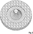
- the toothing of the insert 2 of the rotor grinding disk 20 runs, as in FIG Fig. 2 seen, arcuate radially outward from the center of the insert.
- the recognizable grooves of the toothing take up the grinding stock, which is moved outward by the rotational movement of the rotor in conjunction with the centrifugal forces that occur and passes into the remaining grinding gap between the stator grinding disk 10 and rotor grinding disk 20 for fine grinding.
- a conical annular gap 6 can be formed for the ground material.
Description
Die Erfindung betrifft eine Mahlsteinanordnung für ein Scheibenmahlwerk zur Zerkleinerung von Mahlgut, insbesondere körnigem Material im Nahrungsmittelbereich, bestehend aus einer festen, Statormahlscheibe sowie einer angetriebenen, Rotormahlscheibe, welche unter Einhaltung eines Mahlspalts konzentrisch übereinander angeordnet sind, wobei die Statormahlscheibe eine zentrische Öffnung zum Aufgeben des Mahlguts aufweist und die Mahlscheiben aus einem Natur- oder Kunststeinmaterial bestehen, gemäß Patentanspruch 1.The invention relates to a grinding stone arrangement for a disc grinder for the comminution of grist, in particular granular material in the food sector, consisting of a fixed, stator grinding disc and a driven, rotor grinding disc, which are arranged concentrically one above the other while maintaining a grinding gap, the stator grinding disc having a central opening for giving up the Has grist and the grinding disks consist of a natural or artificial stone material, according to claim 1.
Mahlsteinanordnungen für Körnermühlen gehören seit vielen Jahrzehnten zum Stand der Technik. Grundsätzlich besteht eine solche Mahlsteinanordnung, welche das eigentliche Mahlwerk bildet, aus zwei ringförmigen Mahlsteinen. Ein erster Mahlstein ist üblicherweise ortsfest ausgeführt. Ein zweiter Mahlstein steht mit einem Antrieb in Verbindung und ist in der Lage, eine Rotationsbewegung auszuführen. Am ortsfesten Mahlstein, auch als Statormahlstein bezeichnet, befindet sich eine Zulauföffnung bzw. ein Zulauftrichter für das Mahlgut, z.B. Körner.Grinding stone arrangements for grain mills have been state of the art for many decades. Basically, such a grinding stone arrangement, which forms the actual grinder, consists of two ring-shaped grinding stones. A first millstone is usually designed to be stationary. A second grinding stone is connected to a drive and is able to execute a rotational movement. On the stationary grinding stone, also known as a stator grinding stone, there is an inlet opening or an inlet funnel for the ground material, e.g. grains.
Der rotierende Mahlstein sitzt üblicherweise an einer Läufernabe, die auf einer von einem Elektromotor angetriebenen Welle befindlich ist. Eine Mahlsteinanordnung gemäß dem Oberbegriff des Anspruchs 1 ist in der
Aus der
Bei der Granulatmühle für Kunststoffabfälle gemäß
Aus der
In diesem Sinne umfasst der Bearbeitungskörper zum Zerkleinern eines Aufgabeguts als Metallgusskörper eine Gussträgermatrix und wenigstens einen in der Gussträgermatrix eingebetteten, die Verschleißfestigkeit einer Funktions- bzw. Verschleißfläche des Bearbeitungskörpers erhöhenden Einlegekörper.In this sense, the processing body for comminuting a feed material comprises a cast metal body as a cast metal body and at least one insert body which is embedded in the cast carrier matrix and increases the wear resistance of a functional or wear surface of the processing body.
Der wenigstens eine Einlegekörper ist ein Press- oder Sinterkörper einer Mischung aus Metallpulver und Hartstoffmaterial oder ein Druckgusskörper, weicher ein Hartstoffmaterial in einer Druckgussmatrix aus Druckgussmetall umfasst.The at least one insert body is a pressed or sintered body of a mixture of metal powder and hard material or a die-cast body which comprises a hard material in a die-cast matrix made of die-cast metal.
Bei dem Mahlwerkzeug zur Zerkleinerung von körnigem Material aus dem Lebensmittelbereich gemäß
Aus dem Vorgenannten ist es Aufgabe der Erfindung, eine weiterentwickelte Mahlsteinanordnung sowie ein Scheibenmahlwerk zur Zerkleinerung von Mahlgut, insbesondere körnigem Material im Nahrungsmittelbereich anzugeben, welches in der Lage ist, gleiche Mahlleistungen mit geringerem Energieeinsatz bezüglich des Antriebs des Mahlwerks zu erreichen, wobei eine unerwünschte Erhöhung der Temperatur des Mahlguts bei dessen Zerkleinerung verhindert wird.From the above, it is the object of the invention to provide a further developed grinding stone arrangement and a disc grinder for comminuting ground material, in particular granular material in the food sector, which is able to achieve the same grinding performance with less energy input with regard to the drive of the grinding mechanism, an undesirable increase the temperature of the grist is prevented from being crushed.
Die Lösung der Aufgabe der Erfindung erfolgt durch eine Mahlsteinanordnung gemäß der Merkmalskombination nach Patentanspruch 1, wobei die Unteransprüche mindestens zweckmäßige Ausgestaltungen und Weiterbildungen darstellen.The object of the invention is achieved by means of a grinding stone arrangement according to the combination of features according to patent claim 1, the subclaims representing at least useful embodiments and developments.
Es wird demnach von einer Mahlsteinanordnung für ein Scheibenmahlwerk zur Zerkleinerung von Mahlgut ausgegangen. Bei diesem Mahlgut handelt es sich insbesondere um körniges Material im Lebensmittel- und Nahrungsmittelbereich. Die Mahlsteinanordnung besteht aus einer festen Statormahlscheibe sowie einer angetriebenen Rotormahlscheibe.It is therefore based on a grinding stone arrangement for a disc grinder for comminuting grist. This grist is in particular a granular material in the food and food sector. The grinding stone arrangement consists of a fixed stator grinding disk and a driven rotor grinding disk.
Statormahlscheibe und Rotormahlscheibe sind unter Einhaltung eines Mahlspalts, der gegebenenfalls verstellbar ist, konzentrisch übereinander angeordnet.The stator grinding disk and rotor grinding disk are arranged concentrically one above the other while maintaining a grinding gap, which is optionally adjustable.
Die Statormahlscheibe weist eine mittige bzw. zentrische Öffnung zum Aufgeben des Mahlguts auf. Die Mahlscheiben bestehen aus einem Natur- oder Kunststeinmaterial.The stator grinding disk has a central or central opening for feeding in the grist. The grinding discs are made of a natural or artificial stone material.
Erfindungsgemäß weist die Statormahlscheibe im Bereich, welcher die Öffnung zur Mahlgutaufgabe umgibt, einen, mit der Mahlscheibe verbundenen, sowohl zum Zentrum der Öffnung als auch zum Mahlspalt gerichteten, ersten Einsatz auf.According to the invention, the stator grinding disk has a first insert, connected to the grinding disk and directed both towards the center of the opening and towards the grinding gap, in the area surrounding the opening for feeding the material to be ground.
Weiterhin besitzt die Rotormahlscheibe einen mit ihr drehfest verbundenen, zweiten Einsatz, welcher im Längsschnitt die Form eines Kegels oder eines Kegelstumpfes besitzt, wobei die Kegel- oder Kegelstumpfspitze in die Öffnung zur Mahlgutaufgabe hineinragt.Furthermore, the rotor grinding disk has a second insert connected to it in a rotationally fixed manner, which in longitudinal section has the shape of a cone or a Has truncated cone, wherein the cone or truncated cone tip protrudes into the opening for the grinding stock feed.
Der erste und der zweite Einsatz weisen an ihren zum Mahlspalt und/oder zur Öffnung hin gerichteten Oberflächen eine Strukturierung auf.The first and the second insert have a structure on their surfaces directed towards the grinding gap and / or towards the opening.
Erfindungsgemäß ist darüber hinaus das Material der Einsätze vom Material der Mahlscheiben unterschiedlich gewählt.According to the invention, the material of the inserts is also chosen differently from the material of the grinding disks.
So bestehen die Einsätze bevorzugt aus einem keramischen Material, aus Metall oder Kunststoff größerer Härte.The inserts are preferably made of a ceramic material, metal or plastic of greater hardness.
Die erwähnte Strukturierung ist als Verzahnung ausgebildet und weist eine Vielzahl von Schneid- oder Schlagkanten auf.The aforementioned structuring is designed as a toothing and has a large number of cutting or impact edges.
Die Verzahnung des Einsatzes der Rotormahlscheibe ist bevorzugt bogenförmig radial zum Zentrum nach außen verlaufend ausgebildet.The toothing of the insert of the rotor grinding disk is preferably designed to run in an arc shape radially to the center outwards.
Die Verzahnung des Einsatzes der Statormahlscheibe ist sowohl in Richtung der Drehachse der Rotormahlscheibe als auch zum Mahlspalt hin gerichtet ausgebildet.The toothing of the insert of the stator grinding disk is designed both in the direction of the axis of rotation of the rotor grinding disk and in the direction of the grinding gap.
Zwischen dem Einsatz der Statormahlscheibe und dem Einsatz der Rotormahlscheibe ist im Bereich der Öffnung zur Aufgabe des Mahlguts ein konischer Ringspalt für die Mahlgutzuführung vorgesehen.Between the insert of the stator grinding disc and the insert of the rotor grinding disc, a conical annular gap for the grinding stock feed is provided in the area of the opening for feeding in the grist.
Die bogenförmig verlaufende Verzahnung kann mindestens eine Unstetigkeitsstelle je Bogennut aufweisen oder einen spiralförmigen Verlauf besitzen.The curved toothing can have at least one point of discontinuity per curved groove or have a spiral course.
Die Mahlscheibeneinsätze schließen im Bereich des im Wesentlichen üblicherweise horizontal verlaufenden Mahlspalts mit der Oberfläche der jeweiligen Mahlscheibe bündig ab. Das vorzerkleinerte Mahlgut wird also zur Feinzerkleinerung in den verbleibenden Mahlspalt zwischen Stator- und Rotormahlscheibe eingebracht.The grinding disk inserts are flush with the surface of the respective grinding disk in the area of the grinding gap, which is essentially usually horizontal. The pre-comminuted ground material is therefore introduced into the remaining grinding gap between the stator and rotor grinding disks for fine grinding.
Mittels der Mahlscheibeneinsätze ist also eine Vorzerkleinerung des Mahlguts möglich, dessen Feinzerkleinerung über den Mahlspalt zwischen den verbleibenden einsatzfreien Abschnitten der Stator- und Rotormahlscheibe realisiert wird.By means of the grinding disk inserts, a pre-grinding of the ground material is possible, its fine grinding via the grinding gap between the remaining unused sections of the stator and rotor grinding disk is realized.
Die Erfindung soll nachstehend anhand eines Ausführungsbeispiels sowie unter Zuhilfenahme von Figuren näher erläutert werden.The invention is to be explained in more detail below using an exemplary embodiment and with the aid of figures.
Hierbei zeigen:
- Fig. 1
- eine Draufsicht auf eine Mahlsteinanordnung mit Blick in Richtung Öffnung zur Aufgabe des Mahlguts mit erkennbarer Rotormahlscheibe, welche eine Strukturierung in Form einer Verzahnung aufweist, sowie mit erkennbaren Verzahnungsabschnitten der Statormahlscheibe bzw. des Einsatzes der Statormahlscheibe;
- Fig. 2
- eine perspektivische Draufsicht auf die Rotormahlscheibe, welche einen Einsatz in Kegelstumpfform besitzt, wobei die Oberfläche des Einsatzes eine Verzahnung aufweist, die bogenförmig vom Zentrum des Einsatzes zum äußeren Rand eine Vielzahl von Nuten aufweist und wobei die Nuten eine Unstetigkeitsstelle in ihrem bogenförmigen Verlauf besitzen;
- Fig. 3
- eine Draufsicht auf die zum Mahlspalt gerichtete Unterseite der Statormahlscheibe mit Einsatz, wobei der Einsatz eine Verzahnungsstruktur sowohl radial als auch axial verlaufend besitzt, und
- Fig. 4
- eine Längsschnittdarstellung durch eine Mahlsteinanordnung, umfassend Statormahlscheibe und Rotormahlscheibe, welche die erfindungsgemäßen Einsätze aufweist.
- Fig. 1
- a plan view of a grinding stone arrangement with a view in the direction of the opening for feeding the ground material with a recognizable rotor grinding disk, which has a structure in the form of a toothing, as well as with recognizable toothing sections of the stator grinding disk or the insert of the stator grinding disk;
- Fig. 2
- a perspective top view of the rotor grinding disk, which has an insert in the shape of a truncated cone, the surface of the insert having a toothing which has a plurality of grooves in an arc from the center of the insert to the outer edge and the grooves have a point of discontinuity in their arcuate course;
- Fig. 3
- a plan view of the underside of the stator grinding disk with insert facing the grinding gap, the insert having a toothed structure extending both radially and axially, and
- Fig. 4
- a longitudinal sectional view through a grinding stone arrangement, comprising stator grinding disk and rotor grinding disk, which has the inserts according to the invention.
Die Längsschnittdarstellung nach
Die Rotormahlscheibe 20 ist mit einer nicht dargestellten Antriebsvorrichtung drehfest verbunden.The
Die Mahlsteinanordnung gemäß der Prinzipdarstellung nach
Zwischen der Statormahlscheibe 10 und der Rotormahlscheibe 20 befindet sich ein Mahlspalt 4, welcher durch eine beabstandete Lagerung der Mahlscheiben 10; 20 erhalten wird.Between the
Die Statormahlscheibe 10 weist im Bereich, der die Öffnung 3 umgibt, einen mit der Mahlscheibe verbundenen, sowohl zum Zentrum der Öffnung 3 als auch zum Mahlspalt 4 hin gerichteten ersten Einsatz 1 auf.In the area surrounding the
Weiterhin besitzt die Rotormahlscheibe 20 einen mit ihr drehfest verbundenen zweiten Einsatz 2, welcher im Längsschnitt die Form eines Kegels oder eines Kegelstumpfes besitzt.Furthermore, the
Die Kegel- oder Kegelstumpfspitze 5 reicht in die Öffnung 3 zur Mahlgutaufgabe hinein.The cone or
Wie aus den
Das Material der Statormahlscheibe 10 und der Rotormahlscheibe 20 ist Natur- oder Kunststein. Das Material der Einsätze 1; 2 ist bevorzugt Keramik, Metall oder ein Kunststoff größerer Härte.The material of the
Aus den
Die Verzahnung des Einsatzes 2 der Rotormahlscheibe 20 verläuft, wie in der
Dabei können im bogenförmigen Verlauf Unstetigkeitsstellen vorhanden sein.There may be points of discontinuity in the arcuate course.
Die erkennbaren Nuten der Verzahnung nehmen das Mahlgut auf, welches durch die Rotationsbewegung des Rotors in Verbindung mit entstehenden Fliehkräften nach außen bewegt wird und in den verbleibenden Mahlspalt zwischen Statormahlscheibe 10 und Rotormahlscheibe 20 zur Feinzerkleinerung gelangt.The recognizable grooves of the toothing take up the grinding stock, which is moved outward by the rotational movement of the rotor in conjunction with the centrifugal forces that occur and passes into the remaining grinding gap between the
Die
Aus der
Mit Aufgabe des Mahlguts über die Öffnung 3 kommt es durch die Wirkung der Einsätze 1; 2 und deren Oberflächenstrukturierung zu einer Vorzerkleinerung des Mahlguts, dessen Feinzerkleinerung über den Mahlspalt 4 zwischen den verbleibenden einsatzfreien Abschnitten der Stator- und Rotormahlscheibe realisiert wird.With the task of the grist via the
Claims (7)
- A millstone arrangement for a flat burr grinder for grinding material to be ground, in particular granular material in the food sector, composed of a fixed stator grinding disc (10) as well as a driven rotor grinding disc (10), which are superimposed concentrically while keeping a grinding gap (4), wherein the stator grinding disc (10) has a centric opening (3) for feeding the material to be ground, and the grinding discs (10; 20) are composed of a natural stone material or an artificial stone material, the rotor grinding disc (20) furthermore has a second insert (2) being in connection with it in a torque-proof manner, which insert has the shape of a cone or a truncated cone in a longitudinal section, wherein the tip (5) of the cone or the truncated cone protrudes into the opening (3) for feeding the material to be ground, and the second insert (2) has a structuring at its surfaces directed toward the grinding gap (4) and/or toward the opening (3),
characterized in that
in the area surrounding the opening (3) for feeding the material to be ground, the stator grinding disc (10) has a first insert (1) having a structuring, which insert is in connection with the grinding disc (10) and directed both toward the center of the opening (3) and toward the grinding gap, the structuring is formed as a toothing extending radially and axially, i.e. both in the direction of the axis of rotation of the rotor grinding disc (20) and toward the grinding gap (4), and the material of the inserts (1; 2) is selected to be different from the material of the grinding discs (10; 20). - The millstone arrangement according to claim 1,
characterized in that
the inserts (1; 2) consist of ceramics or metal. - The millstone arrangement according to any one of the preceding claims,
characterized in that
the toothing has a plurality of cutting edges or impact edges. - The millstone arrangement according to claim 3,
characterized in that
the toothing of the insert (2) of the rotor grinding disc (20) is formed to extend in an arcuate manner radially outward from the center. - The millstone arrangement according to any one of the preceding claims,
characterized in that
between the insert (1) of the stator grinding disc (10) and the insert (2) of the rotor grinding disc (10), a conical annular gap (6) for the material to be ground is formed in the area of the opening (3) for feeding the material to be ground. - The millstone arrangement according to claim 4,
characterized in that
the toothing extending in an arcuate manner has at least one point of discontinuity per arcuate groove. - The millstone arrangement according to any one of the preceding claims,
characterized in that
the grinding disc inserts (1; 2) are flush with the upper surface of the respective grinding disc (10; 20) in the area of the grinding gap (4).
Priority Applications (1)
| Application Number | Priority Date | Filing Date | Title |
|---|---|---|---|
| PL16798221T PL3383542T3 (en) | 2015-12-03 | 2016-11-21 | Millstone arrangement for a flat burr grinder for grinding material to be ground |
Applications Claiming Priority (2)
| Application Number | Priority Date | Filing Date | Title |
|---|---|---|---|
| DE102015015622 | 2015-12-03 | ||
| PCT/EP2016/078319 WO2017093062A1 (en) | 2015-12-03 | 2016-11-21 | Millstone arrangement for a flat burr grinder for grinding material to be ground |
Publications (2)
| Publication Number | Publication Date |
|---|---|
| EP3383542A1 EP3383542A1 (en) | 2018-10-10 |
| EP3383542B1 true EP3383542B1 (en) | 2021-01-06 |
Family
ID=57348701
Family Applications (1)
| Application Number | Title | Priority Date | Filing Date |
|---|---|---|---|
| EP16798221.4A Active EP3383542B1 (en) | 2015-12-03 | 2016-11-21 | Millstone arrangement for a flat burr grinder for grinding material to be ground |
Country Status (4)
| Country | Link |
|---|---|
| EP (1) | EP3383542B1 (en) |
| DE (1) | DE102016122337A1 (en) |
| PL (1) | PL3383542T3 (en) |
| WO (1) | WO2017093062A1 (en) |
Families Citing this family (2)
| Publication number | Priority date | Publication date | Assignee | Title |
|---|---|---|---|---|
| CN107899666A (en) * | 2017-11-25 | 2018-04-13 | 防城港市润禾农林科技有限公司 | A kind of powder for natural perfume material grinds device |
| CN109277137B (en) * | 2018-10-10 | 2023-12-08 | 湖州职业技术学院 | Gap adjusting mechanism |
Family Cites Families (6)
| Publication number | Priority date | Publication date | Assignee | Title |
|---|---|---|---|---|
| FR317706A (en) * | 1902-01-11 | 1902-09-23 | Witham | Improvements to devices for crushing, grinding or reducing lime, ash, sandstone, limestone, refractory clay, quartz and other minerals and materials |
| US3926380A (en) * | 1974-05-24 | 1975-12-16 | Emcee Corp | Grain milling device |
| AT384751B (en) | 1983-12-29 | 1988-01-11 | Osttiroler Getreidemuehlenbau | MILLSTONE |
| DE19530428C1 (en) | 1995-08-18 | 1996-12-19 | Albrecht Fritzsche | Granulating mill for plastic scrap |
| EP1818099A1 (en) | 2006-02-13 | 2007-08-15 | Eldom Rothrist AG | Grinding device for granular material, especially for alimentary use |
| DE102010043353A1 (en) | 2010-11-03 | 2012-05-03 | Shw Casting Technologies Gmbh | Processing body for crushing a feed |
-
2016
- 2016-11-21 EP EP16798221.4A patent/EP3383542B1/en active Active
- 2016-11-21 DE DE102016122337.9A patent/DE102016122337A1/en not_active Withdrawn
- 2016-11-21 PL PL16798221T patent/PL3383542T3/en unknown
- 2016-11-21 WO PCT/EP2016/078319 patent/WO2017093062A1/en active Application Filing
Non-Patent Citations (1)
| Title |
|---|
| None * |
Also Published As
| Publication number | Publication date |
|---|---|
| EP3383542A1 (en) | 2018-10-10 |
| DE102016122337A1 (en) | 2017-06-08 |
| PL3383542T3 (en) | 2021-10-18 |
| WO2017093062A1 (en) | 2017-06-08 |
Similar Documents
| Publication | Publication Date | Title |
|---|---|---|
| EP2984973A1 (en) | Grinder for grinding coffee beans and coffee machine with such a grinder | |
| EP2482987B1 (en) | Method and device for comminuting ore | |
| EP2404534A1 (en) | Grinder | |
| EP3383542B1 (en) | Millstone arrangement for a flat burr grinder for grinding material to be ground | |
| EP3202290B1 (en) | Grinder, mill, device for preparing coffee with a mill and method of milling | |
| EP3356049A1 (en) | Processing device, and processing element and wall cladding element for such a processing device | |
| EP2253380A1 (en) | Device for grinding dispensed products | |
| EP2440371B1 (en) | Grinding and/or polishing tool, and production method | |
| EP3536405A1 (en) | Agitator mill with asynchronous pin assembly | |
| EP3840620B1 (en) | Grinder for grinding material to be ground | |
| EP0998980B1 (en) | Motor driven parallel-shaft disintegrator | |
| DE2353907B2 (en) | IMPACT MILL | |
| WO2020143997A1 (en) | Grinding roller having peripheral elements | |
| DE102007060072B4 (en) | Whirlwind Mill | |
| EP2548648B1 (en) | Mill for comminuting of material | |
| EP1207010B1 (en) | Grinding machine | |
| EP2052778B1 (en) | Whirlpool mill and grinding tool and grinding ring for same | |
| DE3535245A1 (en) | Device for milling cereals or the like | |
| DE915294C (en) | Blower mill | |
| EP1701794B1 (en) | Disc mill | |
| DE10018005A1 (en) | Method and device for reducing splinter material to powder feeds material to be processed through an inlet in an external wall into a processing chamber for shredding by a rotor. | |
| DE102007051393B4 (en) | Eddy current mill, as well as grinding tool and Mahlring for it | |
| DE102007057565A1 (en) | Eddy current mill, rotor and stator, as well as grinding track insert and grinding tool insert for it | |
| CH698090B1 (en) | Mill | |
| DE670606C (en) | Grinder or disk mill |
Legal Events
| Date | Code | Title | Description |
|---|---|---|---|
| STAA | Information on the status of an ep patent application or granted ep patent |
Free format text: STATUS: UNKNOWN |
|
| STAA | Information on the status of an ep patent application or granted ep patent |
Free format text: STATUS: THE INTERNATIONAL PUBLICATION HAS BEEN MADE |
|
| PUAI | Public reference made under article 153(3) epc to a published international application that has entered the european phase |
Free format text: ORIGINAL CODE: 0009012 |
|
| STAA | Information on the status of an ep patent application or granted ep patent |
Free format text: STATUS: REQUEST FOR EXAMINATION WAS MADE |
|
| 17P | Request for examination filed |
Effective date: 20180620 |
|
| AK | Designated contracting states |
Kind code of ref document: A1 Designated state(s): AL AT BE BG CH CY CZ DE DK EE ES FI FR GB GR HR HU IE IS IT LI LT LU LV MC MK MT NL NO PL PT RO RS SE SI SK SM TR |
|
| AX | Request for extension of the european patent |
Extension state: BA ME |
|
| DAV | Request for validation of the european patent (deleted) | ||
| DAX | Request for extension of the european patent (deleted) | ||
| STAA | Information on the status of an ep patent application or granted ep patent |
Free format text: STATUS: EXAMINATION IS IN PROGRESS |
|
| 17Q | First examination report despatched |
Effective date: 20190904 |
|
| GRAP | Despatch of communication of intention to grant a patent |
Free format text: ORIGINAL CODE: EPIDOSNIGR1 |
|
| STAA | Information on the status of an ep patent application or granted ep patent |
Free format text: STATUS: GRANT OF PATENT IS INTENDED |
|
| INTG | Intention to grant announced |
Effective date: 20200922 |
|
| GRAS | Grant fee paid |
Free format text: ORIGINAL CODE: EPIDOSNIGR3 |
|
| GRAA | (expected) grant |
Free format text: ORIGINAL CODE: 0009210 |
|
| STAA | Information on the status of an ep patent application or granted ep patent |
Free format text: STATUS: THE PATENT HAS BEEN GRANTED |
|
| AK | Designated contracting states |
Kind code of ref document: B1 Designated state(s): AL AT BE BG CH CY CZ DE DK EE ES FI FR GB GR HR HU IE IS IT LI LT LU LV MC MK MT NL NO PL PT RO RS SE SI SK SM TR |
|
| REG | Reference to a national code |
Ref country code: GB Ref legal event code: FG4D Free format text: NOT ENGLISH |
|
| REG | Reference to a national code |
Ref country code: AT Ref legal event code: REF Ref document number: 1351785 Country of ref document: AT Kind code of ref document: T Effective date: 20210115 Ref country code: CH Ref legal event code: EP |
|
| REG | Reference to a national code |
Ref country code: DE Ref legal event code: R096 Ref document number: 502016012154 Country of ref document: DE |
|
| REG | Reference to a national code |
Ref country code: IE Ref legal event code: FG4D Free format text: LANGUAGE OF EP DOCUMENT: GERMAN |
|
| REG | Reference to a national code |
Ref country code: NL Ref legal event code: MP Effective date: 20210106 |
|
| REG | Reference to a national code |
Ref country code: LT Ref legal event code: MG9D |
|
| PG25 | Lapsed in a contracting state [announced via postgrant information from national office to epo] |
Ref country code: LT Free format text: LAPSE BECAUSE OF FAILURE TO SUBMIT A TRANSLATION OF THE DESCRIPTION OR TO PAY THE FEE WITHIN THE PRESCRIBED TIME-LIMIT Effective date: 20210106 Ref country code: BG Free format text: LAPSE BECAUSE OF FAILURE TO SUBMIT A TRANSLATION OF THE DESCRIPTION OR TO PAY THE FEE WITHIN THE PRESCRIBED TIME-LIMIT Effective date: 20210406 Ref country code: FI Free format text: LAPSE BECAUSE OF FAILURE TO SUBMIT A TRANSLATION OF THE DESCRIPTION OR TO PAY THE FEE WITHIN THE PRESCRIBED TIME-LIMIT Effective date: 20210106 Ref country code: HR Free format text: LAPSE BECAUSE OF FAILURE TO SUBMIT A TRANSLATION OF THE DESCRIPTION OR TO PAY THE FEE WITHIN THE PRESCRIBED TIME-LIMIT Effective date: 20210106 Ref country code: GR Free format text: LAPSE BECAUSE OF FAILURE TO SUBMIT A TRANSLATION OF THE DESCRIPTION OR TO PAY THE FEE WITHIN THE PRESCRIBED TIME-LIMIT Effective date: 20210407 Ref country code: NO Free format text: LAPSE BECAUSE OF FAILURE TO SUBMIT A TRANSLATION OF THE DESCRIPTION OR TO PAY THE FEE WITHIN THE PRESCRIBED TIME-LIMIT Effective date: 20210406 Ref country code: PT Free format text: LAPSE BECAUSE OF FAILURE TO SUBMIT A TRANSLATION OF THE DESCRIPTION OR TO PAY THE FEE WITHIN THE PRESCRIBED TIME-LIMIT Effective date: 20210506 |
|
| PG25 | Lapsed in a contracting state [announced via postgrant information from national office to epo] |
Ref country code: SE Free format text: LAPSE BECAUSE OF FAILURE TO SUBMIT A TRANSLATION OF THE DESCRIPTION OR TO PAY THE FEE WITHIN THE PRESCRIBED TIME-LIMIT Effective date: 20210106 Ref country code: RS Free format text: LAPSE BECAUSE OF FAILURE TO SUBMIT A TRANSLATION OF THE DESCRIPTION OR TO PAY THE FEE WITHIN THE PRESCRIBED TIME-LIMIT Effective date: 20210106 Ref country code: LV Free format text: LAPSE BECAUSE OF FAILURE TO SUBMIT A TRANSLATION OF THE DESCRIPTION OR TO PAY THE FEE WITHIN THE PRESCRIBED TIME-LIMIT Effective date: 20210106 |
|
| PG25 | Lapsed in a contracting state [announced via postgrant information from national office to epo] |
Ref country code: IS Free format text: LAPSE BECAUSE OF FAILURE TO SUBMIT A TRANSLATION OF THE DESCRIPTION OR TO PAY THE FEE WITHIN THE PRESCRIBED TIME-LIMIT Effective date: 20210506 |
|
| REG | Reference to a national code |
Ref country code: DE Ref legal event code: R097 Ref document number: 502016012154 Country of ref document: DE |
|
| PG25 | Lapsed in a contracting state [announced via postgrant information from national office to epo] |
Ref country code: SM Free format text: LAPSE BECAUSE OF FAILURE TO SUBMIT A TRANSLATION OF THE DESCRIPTION OR TO PAY THE FEE WITHIN THE PRESCRIBED TIME-LIMIT Effective date: 20210106 Ref country code: EE Free format text: LAPSE BECAUSE OF FAILURE TO SUBMIT A TRANSLATION OF THE DESCRIPTION OR TO PAY THE FEE WITHIN THE PRESCRIBED TIME-LIMIT Effective date: 20210106 Ref country code: CZ Free format text: LAPSE BECAUSE OF FAILURE TO SUBMIT A TRANSLATION OF THE DESCRIPTION OR TO PAY THE FEE WITHIN THE PRESCRIBED TIME-LIMIT Effective date: 20210106 |
|
| PLBE | No opposition filed within time limit |
Free format text: ORIGINAL CODE: 0009261 |
|
| STAA | Information on the status of an ep patent application or granted ep patent |
Free format text: STATUS: NO OPPOSITION FILED WITHIN TIME LIMIT |
|
| PG25 | Lapsed in a contracting state [announced via postgrant information from national office to epo] |
Ref country code: DK Free format text: LAPSE BECAUSE OF FAILURE TO SUBMIT A TRANSLATION OF THE DESCRIPTION OR TO PAY THE FEE WITHIN THE PRESCRIBED TIME-LIMIT Effective date: 20210106 Ref country code: RO Free format text: LAPSE BECAUSE OF FAILURE TO SUBMIT A TRANSLATION OF THE DESCRIPTION OR TO PAY THE FEE WITHIN THE PRESCRIBED TIME-LIMIT Effective date: 20210106 Ref country code: SK Free format text: LAPSE BECAUSE OF FAILURE TO SUBMIT A TRANSLATION OF THE DESCRIPTION OR TO PAY THE FEE WITHIN THE PRESCRIBED TIME-LIMIT Effective date: 20210106 |
|
| 26N | No opposition filed |
Effective date: 20211007 |
|
| PG25 | Lapsed in a contracting state [announced via postgrant information from national office to epo] |
Ref country code: ES Free format text: LAPSE BECAUSE OF FAILURE TO SUBMIT A TRANSLATION OF THE DESCRIPTION OR TO PAY THE FEE WITHIN THE PRESCRIBED TIME-LIMIT Effective date: 20210106 Ref country code: AL Free format text: LAPSE BECAUSE OF FAILURE TO SUBMIT A TRANSLATION OF THE DESCRIPTION OR TO PAY THE FEE WITHIN THE PRESCRIBED TIME-LIMIT Effective date: 20210106 |
|
| PG25 | Lapsed in a contracting state [announced via postgrant information from national office to epo] |
Ref country code: SI Free format text: LAPSE BECAUSE OF FAILURE TO SUBMIT A TRANSLATION OF THE DESCRIPTION OR TO PAY THE FEE WITHIN THE PRESCRIBED TIME-LIMIT Effective date: 20210106 |
|
| PG25 | Lapsed in a contracting state [announced via postgrant information from national office to epo] |
Ref country code: IT Free format text: LAPSE BECAUSE OF FAILURE TO SUBMIT A TRANSLATION OF THE DESCRIPTION OR TO PAY THE FEE WITHIN THE PRESCRIBED TIME-LIMIT Effective date: 20210106 |
|
| PG25 | Lapsed in a contracting state [announced via postgrant information from national office to epo] |
Ref country code: IS Free format text: LAPSE BECAUSE OF FAILURE TO SUBMIT A TRANSLATION OF THE DESCRIPTION OR TO PAY THE FEE WITHIN THE PRESCRIBED TIME-LIMIT Effective date: 20210506 |
|
| PG25 | Lapsed in a contracting state [announced via postgrant information from national office to epo] |
Ref country code: MC Free format text: LAPSE BECAUSE OF FAILURE TO SUBMIT A TRANSLATION OF THE DESCRIPTION OR TO PAY THE FEE WITHIN THE PRESCRIBED TIME-LIMIT Effective date: 20210106 |
|
| PG25 | Lapsed in a contracting state [announced via postgrant information from national office to epo] |
Ref country code: LU Free format text: LAPSE BECAUSE OF NON-PAYMENT OF DUE FEES Effective date: 20211121 Ref country code: BE Free format text: LAPSE BECAUSE OF NON-PAYMENT OF DUE FEES Effective date: 20211130 |
|
| REG | Reference to a national code |
Ref country code: BE Ref legal event code: MM Effective date: 20211130 |
|
| PG25 | Lapsed in a contracting state [announced via postgrant information from national office to epo] |
Ref country code: IE Free format text: LAPSE BECAUSE OF NON-PAYMENT OF DUE FEES Effective date: 20211121 |
|
| PGFP | Annual fee paid to national office [announced via postgrant information from national office to epo] |
Ref country code: PL Payment date: 20221026 Year of fee payment: 7 |
|
| PG25 | Lapsed in a contracting state [announced via postgrant information from national office to epo] |
Ref country code: HU Free format text: LAPSE BECAUSE OF FAILURE TO SUBMIT A TRANSLATION OF THE DESCRIPTION OR TO PAY THE FEE WITHIN THE PRESCRIBED TIME-LIMIT; INVALID AB INITIO Effective date: 20161121 |
|
| PG25 | Lapsed in a contracting state [announced via postgrant information from national office to epo] |
Ref country code: NL Free format text: LAPSE BECAUSE OF NON-PAYMENT OF DUE FEES Effective date: 20210206 Ref country code: CY Free format text: LAPSE BECAUSE OF FAILURE TO SUBMIT A TRANSLATION OF THE DESCRIPTION OR TO PAY THE FEE WITHIN THE PRESCRIBED TIME-LIMIT Effective date: 20210106 |
|
| P01 | Opt-out of the competence of the unified patent court (upc) registered |
Effective date: 20230531 |
|
| PGFP | Annual fee paid to national office [announced via postgrant information from national office to epo] |
Ref country code: GB Payment date: 20231121 Year of fee payment: 8 |
|
| PGFP | Annual fee paid to national office [announced via postgrant information from national office to epo] |
Ref country code: FR Payment date: 20231123 Year of fee payment: 8 Ref country code: DE Payment date: 20231129 Year of fee payment: 8 Ref country code: CH Payment date: 20231201 Year of fee payment: 8 Ref country code: AT Payment date: 20231117 Year of fee payment: 8 |
|
| PGFP | Annual fee paid to national office [announced via postgrant information from national office to epo] |
Ref country code: PL Payment date: 20231030 Year of fee payment: 8 |