EP3383291B1 - Medizinisches instrument und medizinisches instrumentarium - Google Patents
Medizinisches instrument und medizinisches instrumentarium Download PDFInfo
- Publication number
- EP3383291B1 EP3383291B1 EP16805150.6A EP16805150A EP3383291B1 EP 3383291 B1 EP3383291 B1 EP 3383291B1 EP 16805150 A EP16805150 A EP 16805150A EP 3383291 B1 EP3383291 B1 EP 3383291B1
- Authority
- EP
- European Patent Office
- Prior art keywords
- coupling device
- coupling
- guide
- clamping
- medical instrument
- Prior art date
- Legal status (The legal status is an assumption and is not a legal conclusion. Google has not performed a legal analysis and makes no representation as to the accuracy of the status listed.)
- Active
Links
Images


Classifications
-
- A—HUMAN NECESSITIES
- A61—MEDICAL OR VETERINARY SCIENCE; HYGIENE
- A61B—DIAGNOSIS; SURGERY; IDENTIFICATION
- A61B17/00—Surgical instruments, devices or methods
- A61B17/56—Surgical instruments or methods for treatment of bones or joints; Devices specially adapted therefor
- A61B17/58—Surgical instruments or methods for treatment of bones or joints; Devices specially adapted therefor for osteosynthesis, e.g. bone plates, screws or setting implements
- A61B17/68—Internal fixation devices, including fasteners and spinal fixators, even if a part thereof projects from the skin
- A61B17/70—Spinal positioners or stabilisers, e.g. stabilisers comprising fluid filler in an implant
- A61B17/7074—Tools specially adapted for spinal fixation operations other than for bone removal or filler handling
- A61B17/7083—Tools for guidance or insertion of tethers, rod-to-anchor connectors, rod-to-rod connectors, or longitudinal elements
-
- A—HUMAN NECESSITIES
- A61—MEDICAL OR VETERINARY SCIENCE; HYGIENE
- A61B—DIAGNOSIS; SURGERY; IDENTIFICATION
- A61B17/00—Surgical instruments, devices or methods
- A61B17/56—Surgical instruments or methods for treatment of bones or joints; Devices specially adapted therefor
- A61B17/58—Surgical instruments or methods for treatment of bones or joints; Devices specially adapted therefor for osteosynthesis, e.g. bone plates, screws or setting implements
- A61B17/68—Internal fixation devices, including fasteners and spinal fixators, even if a part thereof projects from the skin
- A61B17/70—Spinal positioners or stabilisers, e.g. stabilisers comprising fluid filler in an implant
- A61B17/7074—Tools specially adapted for spinal fixation operations other than for bone removal or filler handling
- A61B17/7076—Tools specially adapted for spinal fixation operations other than for bone removal or filler handling for driving, positioning or assembling spinal clamps or bone anchors specially adapted for spinal fixation
- A61B17/7077—Tools specially adapted for spinal fixation operations other than for bone removal or filler handling for driving, positioning or assembling spinal clamps or bone anchors specially adapted for spinal fixation for moving bone anchors attached to vertebrae, thereby displacing the vertebrae
- A61B17/708—Tools specially adapted for spinal fixation operations other than for bone removal or filler handling for driving, positioning or assembling spinal clamps or bone anchors specially adapted for spinal fixation for moving bone anchors attached to vertebrae, thereby displacing the vertebrae with tubular extensions coaxially mounted on the bone anchors
-
- A—HUMAN NECESSITIES
- A61—MEDICAL OR VETERINARY SCIENCE; HYGIENE
- A61B—DIAGNOSIS; SURGERY; IDENTIFICATION
- A61B17/00—Surgical instruments, devices or methods
- A61B17/56—Surgical instruments or methods for treatment of bones or joints; Devices specially adapted therefor
- A61B17/58—Surgical instruments or methods for treatment of bones or joints; Devices specially adapted therefor for osteosynthesis, e.g. bone plates, screws or setting implements
- A61B17/68—Internal fixation devices, including fasteners and spinal fixators, even if a part thereof projects from the skin
- A61B17/70—Spinal positioners or stabilisers, e.g. stabilisers comprising fluid filler in an implant
- A61B17/7001—Screws or hooks combined with longitudinal elements which do not contact vertebrae
- A61B17/7032—Screws or hooks with U-shaped head or back through which longitudinal rods pass
-
- A—HUMAN NECESSITIES
- A61—MEDICAL OR VETERINARY SCIENCE; HYGIENE
- A61B—DIAGNOSIS; SURGERY; IDENTIFICATION
- A61B17/00—Surgical instruments, devices or methods
- A61B17/56—Surgical instruments or methods for treatment of bones or joints; Devices specially adapted therefor
- A61B17/58—Surgical instruments or methods for treatment of bones or joints; Devices specially adapted therefor for osteosynthesis, e.g. bone plates, screws or setting implements
- A61B17/68—Internal fixation devices, including fasteners and spinal fixators, even if a part thereof projects from the skin
- A61B17/70—Spinal positioners or stabilisers, e.g. stabilisers comprising fluid filler in an implant
- A61B17/7074—Tools specially adapted for spinal fixation operations other than for bone removal or filler handling
- A61B17/7076—Tools specially adapted for spinal fixation operations other than for bone removal or filler handling for driving, positioning or assembling spinal clamps or bone anchors specially adapted for spinal fixation
- A61B17/7077—Tools specially adapted for spinal fixation operations other than for bone removal or filler handling for driving, positioning or assembling spinal clamps or bone anchors specially adapted for spinal fixation for moving bone anchors attached to vertebrae, thereby displacing the vertebrae
- A61B17/7079—Tools requiring anchors to be already mounted on an implanted longitudinal or transverse element, e.g. where said element guides the anchor motion
-
- A—HUMAN NECESSITIES
- A61—MEDICAL OR VETERINARY SCIENCE; HYGIENE
- A61B—DIAGNOSIS; SURGERY; IDENTIFICATION
- A61B17/00—Surgical instruments, devices or methods
- A61B17/56—Surgical instruments or methods for treatment of bones or joints; Devices specially adapted therefor
- A61B17/58—Surgical instruments or methods for treatment of bones or joints; Devices specially adapted therefor for osteosynthesis, e.g. bone plates, screws or setting implements
- A61B17/68—Internal fixation devices, including fasteners and spinal fixators, even if a part thereof projects from the skin
- A61B17/70—Spinal positioners or stabilisers, e.g. stabilisers comprising fluid filler in an implant
- A61B17/7074—Tools specially adapted for spinal fixation operations other than for bone removal or filler handling
- A61B17/7083—Tools for guidance or insertion of tethers, rod-to-anchor connectors, rod-to-rod connectors, or longitudinal elements
- A61B17/7085—Tools for guidance or insertion of tethers, rod-to-anchor connectors, rod-to-rod connectors, or longitudinal elements for insertion of a longitudinal element down one or more hollow screw or hook extensions, i.e. at least a part of the element within an extension has a component of movement parallel to the extension's axis
-
- A—HUMAN NECESSITIES
- A61—MEDICAL OR VETERINARY SCIENCE; HYGIENE
- A61B—DIAGNOSIS; SURGERY; IDENTIFICATION
- A61B17/00—Surgical instruments, devices or methods
- A61B17/56—Surgical instruments or methods for treatment of bones or joints; Devices specially adapted therefor
- A61B17/58—Surgical instruments or methods for treatment of bones or joints; Devices specially adapted therefor for osteosynthesis, e.g. bone plates, screws or setting implements
- A61B17/68—Internal fixation devices, including fasteners and spinal fixators, even if a part thereof projects from the skin
- A61B17/70—Spinal positioners or stabilisers, e.g. stabilisers comprising fluid filler in an implant
- A61B17/7074—Tools specially adapted for spinal fixation operations other than for bone removal or filler handling
- A61B17/7091—Tools specially adapted for spinal fixation operations other than for bone removal or filler handling for applying, tightening or removing longitudinal element-to-bone anchor locking elements, e.g. caps, set screws, nuts or wedges
-
- A—HUMAN NECESSITIES
- A61—MEDICAL OR VETERINARY SCIENCE; HYGIENE
- A61B—DIAGNOSIS; SURGERY; IDENTIFICATION
- A61B17/00—Surgical instruments, devices or methods
- A61B17/56—Surgical instruments or methods for treatment of bones or joints; Devices specially adapted therefor
- A61B17/58—Surgical instruments or methods for treatment of bones or joints; Devices specially adapted therefor for osteosynthesis, e.g. bone plates, screws or setting implements
- A61B17/68—Internal fixation devices, including fasteners and spinal fixators, even if a part thereof projects from the skin
- A61B17/70—Spinal positioners or stabilisers, e.g. stabilisers comprising fluid filler in an implant
- A61B17/7001—Screws or hooks combined with longitudinal elements which do not contact vertebrae
- A61B17/7035—Screws or hooks, wherein a rod-clamping part and a bone-anchoring part can pivot relative to each other
- A61B17/7037—Screws or hooks, wherein a rod-clamping part and a bone-anchoring part can pivot relative to each other wherein pivoting is blocked when the rod is clamped
-
- A—HUMAN NECESSITIES
- A61—MEDICAL OR VETERINARY SCIENCE; HYGIENE
- A61B—DIAGNOSIS; SURGERY; IDENTIFICATION
- A61B17/00—Surgical instruments, devices or methods
- A61B17/56—Surgical instruments or methods for treatment of bones or joints; Devices specially adapted therefor
- A61B17/58—Surgical instruments or methods for treatment of bones or joints; Devices specially adapted therefor for osteosynthesis, e.g. bone plates, screws or setting implements
- A61B17/68—Internal fixation devices, including fasteners and spinal fixators, even if a part thereof projects from the skin
- A61B17/70—Spinal positioners or stabilisers, e.g. stabilisers comprising fluid filler in an implant
- A61B17/7074—Tools specially adapted for spinal fixation operations other than for bone removal or filler handling
- A61B17/7076—Tools specially adapted for spinal fixation operations other than for bone removal or filler handling for driving, positioning or assembling spinal clamps or bone anchors specially adapted for spinal fixation
- A61B17/7082—Tools specially adapted for spinal fixation operations other than for bone removal or filler handling for driving, positioning or assembling spinal clamps or bone anchors specially adapted for spinal fixation for driving, i.e. rotating, screws or screw parts specially adapted for spinal fixation, e.g. for driving polyaxial or tulip-headed screws
-
- A—HUMAN NECESSITIES
- A61—MEDICAL OR VETERINARY SCIENCE; HYGIENE
- A61B—DIAGNOSIS; SURGERY; IDENTIFICATION
- A61B17/00—Surgical instruments, devices or methods
- A61B2017/00477—Coupling
-
- A—HUMAN NECESSITIES
- A61—MEDICAL OR VETERINARY SCIENCE; HYGIENE
- A61B—DIAGNOSIS; SURGERY; IDENTIFICATION
- A61B90/00—Instruments, implements or accessories specially adapted for surgery or diagnosis and not covered by any of the groups A61B1/00 - A61B50/00, e.g. for luxation treatment or for protecting wound edges
- A61B90/06—Measuring instruments not otherwise provided for
- A61B2090/067—Measuring instruments not otherwise provided for for measuring angles
Definitions
- the present invention relates to a medical instrument for temporarily coupling to at least two shaft- or sleeve-shaped instruments, comprising a first coupling device for temporarily coupling to a first shaft- or sleeve-shaped instrument and a second coupling device for coupling to a second shaft- or sleeve-shaped instrument, wherein the first coupling device and the second coupling device are arranged or designed to be pivotable relative to one another, which medical instrument comprises a base body on which the first coupling device is held so as to be guided such that it can pivot about a pivot point, in particular spatially remote from the base body, which medical instrument has a first guide device for guiding a movement of the first coupling device along a circular path, the first guide device being at least partially arranged or formed on the base body.
- the present invention relates to a set of medical instruments for implanting a spinal column stabilization system, comprising at least two shaft-shaped or sleeve-shaped instruments.
- a medical instrument of the type described above for implanting a spinal column stabilization system is, for example, from DE 10 2013 108 362 A1 known.
- the known set of instruments includes a number of sleeves which can be coupled to the heads of bone screws, which are designed in particular as polyaxial screws.
- the bone screws are initially anchored in pedicles of vertebrae of the spinal column to be stabilized and are therefore also referred to as pedicle screws.
- connecting rods can easily be inserted into corresponding receptacles on the heads of the pedicle screws.
- Distances between the vertebrae can be adjusted with known distractors, in that the shaft-shaped or sleeve-shaped instruments are in particular displaced parallel to one another and/or pivoted relative to one another. Such an approach is particularly in the DE 10 2012 107 056 A1 described.
- the first guide device comprises two or more guide slots in the shape of a circular arc.
- the development proposed according to the invention makes it possible to couple two shaft-shaped or sleeve-shaped instruments to the medical instrument and to pivot the shaft-shaped or sleeve-shaped instruments relative to one another in a defined manner by relative pivoting of the first coupling device and the second coupling device, and in this way achieve a desired Set angles between these and in particular adjacent vertebrae.
- the heads of the screws of the spinal column fixation system are also aligned in a corresponding manner, and possibly also the shafts of the bone screws.
- the instrument comprises a base body on which the first coupling device is held so that it can pivot about a pivot point.
- the pivot point can be a pivot point that is spatially remote from the base body.
- the fulcrum can be defined by a center point of a ball joint formed between a head and a shank of the screw in the case of a polyaxial screw.
- the medical instrument includes a first guide device for guiding a movement of the first coupling device along a circular path.
- a guide device makes it possible, in particular, to move the first and the second coupling device relative to one another in such a way that they can pivot relative to one another about a center point defined by the circular path.
- a curvature of the circular path can be adapted to a length of the shaft-shaped or sleeve-shaped instruments to be coupled with the coupling devices, so that a center point of the circular path coincides with a pivot point of a polyaxial screw, for example.
- their orientation can be changed in a simple manner. If, for example, shaft-shaped or sleeve-shaped instruments of two different lengths are used, the circular path can be curved in such a way that it corresponds to a mean value of the two different lengths.
- the medical instrument can be formed in a particularly simple manner in that the first guide device is arranged or formed at least partially on the base body and comprises at least one guide slot in the shape of a circular arc.
- the base body can be in the form of a plate or can comprise a plate in which a guide slot in the shape of a circular arc is formed.
- two or more arc-shaped guide slots are formed. These are preferably formed concentrically with one another on the base body.
- first coupling device and the second coupling device are arranged or designed to be displaceable relative to one another.
- the relative displaceability also makes it possible to change a distance between the two shaft-shaped or sleeve-shaped instruments in a targeted manner, and thus also one Distance of the bone screws or their heads that are coupled to the shaft or sleeve-shaped instruments.
- the second coupling device is held displaceably guided on the base body.
- a distance between the first and the second coupling device can be changed in a targeted manner by displacing the second coupling device relative to the base body.
- the second coupling device can be displaced on the base body along a straight and/or curved path.
- first coupling device and/or the second coupling device are designed in the form of a receptacle for a shaft-shaped or sleeve-shaped instrument that defines a longitudinal axis of the coupling device.
- This configuration makes it possible, in particular, to couple the medical instrument to one or two shaft-shaped or sleeve-shaped instruments in a simple manner.
- the medical instrument can be designed in a particularly simple manner if the receptacles are designed in the form of retaining rings or tie bows.
- the retaining rings can be self-contained and have a sufficient extension parallel to the longitudinal axis of the coupling device of the respective coupling device in order to prevent the shaft-shaped or sleeve-shaped instrument from tilting relative to the coupling device as much as possible.
- a holding bow can be C-shaped, for example, and preferably includes an angular range of more than 180° in order to hold the shaft-shaped or sleeve-shaped instrument securely and as captively as possible on one of the two coupling devices.
- At least one protruding coupling projection is arranged or formed on the receptacles for non-positive and/or positive coupling with a shaft-shaped or sleeve-shaped instrument.
- the at least one coupling projection allows the shaft or sleeve-shaped Instrument in a targeted manner, secured for example against rotation relative to the coupling device to engage with it.
- the at least one coupling projection is preferably designed to protrude from an inner wall surface towards the longitudinal axis of the coupling device.
- the at least one coupling projection in particular two, three or more coupling projections can also be provided, engage in corresponding recesses on the shaft-shaped or sleeve-shaped instrument in order to prevent the same from rotating relative to the coupling device.
- the shaft-shaped or sleeve-shaped instrument can also be guided on the coupling device in this way.
- Receptacles that correspond to the at least one coupling projection can in particular be opened pointing radially away from the longitudinal axis of the coupling device.
- the medical instrument preferably comprises two arc-shaped slits arranged concentrically to one another. These make it possible in particular to move the first coupling device with a defined orientation relative to the base body and thus to the second coupling device, in particular to pivot about a common pivot point.
- the medical instrument comprises a first fixing device for fixing the first coupling device in a first alignment position on the base body.
- a relative angle between the first and second coupling device can not only be adjusted in a targeted manner, but also fixed in the first alignment position.
- the first locking device is designed in the form of a clamping device.
- a clamping device can be designed in various ways and enables it to be released and locked quickly and easily.
- the clamping device comprises first and second clamping elements which are coupled to one another via connecting members penetrating the at least one guide slot and comprise a first clamping member for moving the first and second clamping elements towards one another.
- This configuration makes it possible in particular to guide the first coupling device on the base body in a defined manner and to fix the first and second clamping elements by the first clamping member on the base body in the first alignment position by moving them towards one another.
- the first clamping member is designed in the form of a clamping screw which at least partially penetrates the at least one guide slot and can be brought from an adjustment position into a clamping position and vice versa.
- the clamping screw In order to fix the first coupling device in the alignment position on the base body, only the clamping screw has to be brought into the clamping position.
- the clamping screw In order to be able to move the first coupling device again, the clamping screw simply has to be loosened again, ie transferred to the adjustment position, so that the first coupling device can be moved again relative to the base body and relative to the second coupling device.
- a particularly compact design of the medical instrument can be achieved in particular by the first clamping element enclosing or carrying the first receptacle.
- the first clamping element can be designed in one piece with the first receptacle.
- a defined alignment of the receptacle relative to the base body can already be specified during manufacture.
- the medical instrument comprises a locking device for locking the first coupling device on the base body in a basic position in which the longitudinal axes of the coupling device of the at least two coupling devices are aligned parallel to one another are.
- the locking device makes it possible to bring the instrument into a defined basic position in which the longitudinal axes of the coupling device, in particular of the first and second coupling devices, are aligned parallel to one another. Starting from this basic position, the instrument can then be used to set a desired relative angle between the first and the second coupling device, for example after releasing the locking device.
- the locking device comprises a latching connection device with a movable first latching element and a second latching element and if the first and the second latching element are non-positively and/or positively engaged in the basic position and are disengaged in a release position.
- the first coupling device can be moved relative to the base body.
- the snap-in connection device described can be realized in a simple manner and with a minimum number of moving parts. In particular, it can also be optimized for intraoperative handling.
- the snap-in connection device can be designed in a simple manner if the first snap-in element is designed in the form of a snap-in lever which is mounted on the base body in a displaceable and/or pivotable manner and has a projection or a recess which is/are connected to a corresponding recess or a corresponding projection on the first coupling device is engaged in the basic position.
- the first latching element only has to be displaced and/or pivoted in such a way that it disengages from the second latching element, so that the latching connection device assumes the described release position.
- the handling of the instrument can be further improved if the first latching element is mounted such that it can pivot about a pivot axis which runs transversely, in particular perpendicularly, to the longitudinal axis of the coupling device of the first and/or second coupling device.
- the pivot axis can also run parallel to an axis defined by the first guide device, about which the first and the second coupling device can be pivoted relative to one another.
- a display device for displaying an angle between the longitudinal axes of the coupling device of the at least two coupling devices.
- the display device can be formed in a particularly simple manner if it comprises angle markings on the base body and a display element which is arranged or formed on the first coupling device and points to the angle markings. Such a display device can also be easily cleaned intraoperatively, for example by rinsing with water or an isotonic saline solution.
- the display element is arranged or designed on the first and/or second clamping element.
- the medical instrument comprises a second guide device for guiding a movement of the second coupling device along a rectilinear path.
- the second guide device makes it possible, in particular, to move the first and the second coupling device relative to one another along a straight path, that is to say, for example, to change a distance between them in a targeted manner.
- the instrument can be made particularly compact if the second guide device is formed on the base body and includes at least one guide receptacle.
- two guide shots be provided, which allow a particularly stable and path-true guidance of the second coupling device on the base body.
- the second coupling device comprises a rod-shaped or shaft-shaped guide member, which is held guided in or on the at least one guide mount.
- the guide receptacle can be designed in the form of a ring, into which the rod-shaped or shaft-shaped guide member is inserted and held displaceably therein. Two guide receptacles can also be provided, which enable improved guidance of the rod-shaped or shaft-shaped guide member.
- the medical instrument includes a second fixing device for fixing the second coupling device in a second alignment position on the base body.
- the second fixing device makes it possible, in particular, similar to the first fixing device, to now fix the second coupling device in a defined position relative to the base body, namely in the second alignment position. In this way, in particular, a desired distance between the first and the second coupling device can not only be set, but also temporarily fixed.
- the second locking device can be designed in a particularly simple manner if it is designed in the form of a clamping device.
- the second coupling device can be held in the second alignment position in a clamped manner on the base body.
- the second clamping device comprises at least one second clamping member for clamping the guide member to the base body.
- the second clamping element is designed in the form of a clamping screw which penetrates the at least one guide receptacle and has a free shank end of a clamping screw shank in the second Alignment presses against the guide member.
- a groove-shaped guide recess can be formed on the guide member, into which the free shank end of the clamping screw shank presses in the second alignment position.
- the guide recess can prevent the guide member from twisting in the at least one guide receptacle.
- the guide member can optionally also have a non-circular cross section, so that the guide member can also be prevented from twisting about a longitudinal axis in a guide receptacle that has a corresponding internal cross section that is adapted to the cross section of the guide member.
- the guide recess defines end stops for a displacement movement of the guide member relative to the base body. For example, if the free shank end of the clamping screw shank protrudes into the groove-shaped guide recess, the guide member can only be pushed back and forth until the free shank end hits one of the end stops, e.g. facing stop surfaces formed on both sides of the guide recess.
- the object set at the outset is also achieved according to the invention in the case of a set of medical instruments of the type described at the outset in that it comprises one of the advantageous medical instruments described above.
- Medical instruments designed in this way make it particularly easy to implant a spinal column stabilization system, in particular to anchor bone screws, for example in the form of pedicle screws, in vertebral bodies in the desired manner with a predetermined distance and a relative alignment angle in vertebrae of the spinal column.
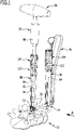
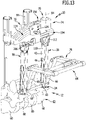
- a set of medical instruments 10 for implanting a spinal column stabilization system 12 is shown as an example.
- the spinal column stabilization system 12 comprises a plurality of bone screws 14, which can be designed in particular in the form of polyaxial screws, with an elongated shaft 16, which is provided with an external thread 18 and defines a longitudinal shaft axis 20, and a head 22, which has a seat 24 for a spherical proximal End 26 of the shank 16 such that the head 22 is pivotable relative to the shank 16 about a center point 28 of the spherical end 26 .
- the head 22 has a generally U-shaped rod receptacle 30 formed between two wall sections 32 which are provided with internally threaded sections.
- a connecting rod 34 of the spinal column stabilization system 12 can be inserted into the rod receptacle 30 and fixed with a fixing screw 36 whose external thread corresponds to the internal thread sections of the wall sections 32 .
- the bone screw 14 can in particular also be designed in such a way that not only can the connecting rod 34 be fixed to the head 22 with the fixing screw 36 , but the head 22 can also be fixed immovably to the spherical end 26 of the shaft 16 .
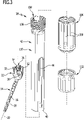
- the set of instruments 10 also includes a plurality of shaft-shaped or sleeve-shaped instruments 38, the distal end 40 of which is designed for temporary coupling to the head 22 in a known manner.
- the instrument 38 can in particular comprise an outer sleeve 42 which, starting from the end 40 , has a slot 44 which extends parallel to a longitudinal axis of the outer sleeve 42 .
- the slot 44 of the instrument 38 can be aligned with the head 22 in such a way that the connecting rod 34 held on an insertion instrument 46 can be inserted into the rod receptacle 30 coming from the side.
- An insertion opening for a free end 48 of the connecting rod 34 is delimited in particular by the wall sections 32, the seat 24 and the fixing screw 36.
- a screw-in instrument 50 is used to secure the connecting rod 34 in the rod receptacle 30; the fixing screw 36 is formed.
- the tool element receptacle 54 is shown as an example in the form of an internal polygon.
- the tool element receptacles of the bone screws 14 are also possible in the form of a polygon socket or a slot.
- the screw-in instrument 50 is equipped with a ratchet handle 56 on the proximal side in order to enable an operator to easily tighten the fixing screw on the head 22 .
- the ratchet handle 56 can be equipped with a torque limiting device 58 so that a predefined tightening torque of the fixing screw 36 is not exceeded.
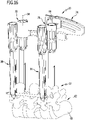
- the required number of bone screws 14 are first screwed into the vertebrae 60 of the spinal column 62 that are to be positioned relative to one another. Bone screws 14 are screwed into the pedicles of the vertebrae 60 for example on both sides of the spinous processes of the vertebrae 60 for optimal stabilization of the spinal column 62 .
- the heads 22 can first be pivoted about the center point 28 relative to the shanks 16 of the bone screws 14 .
- the instruments 38 are used for simple and, in particular, minimally invasive handling of the spinal column stabilization system 12 and the set of instruments 10. These are coupled to the heads 22 and thus form extensions of the same, which protrude from the patient's body.
- the set of instruments 10 can in particular include a distractor 64 with two legs 66 running parallel to one another, the distal ends 68 of which can be coupled to the instruments 38 in the region of their distal ends 40 . Proximal ends of the legs 66 are coupled via a distraction bar 70 with which a distance between the legs 66 can be changed and fixed.
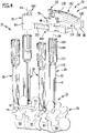
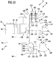
- the set of instruments 10 comprises a further instrument 72 in the form of an angle adjuster 74.
- the angle adjuster 74 is designed for temporary coupling to two instruments 38 and comprises a first coupling device 76 and a second coupling device 78.
- the coupling devices 76 and 78 can be pivoted relative to one another on the instrument 72 arranged or formed. Furthermore, the coupling devices 76 and 78 are also arranged or designed to be displaceable relative to one another on the instrument 72 .
- the angle adjuster 74 comprises a plate-shaped base body 80 on which the first coupling device 76 is held so that it can pivot about a pivot point 82 that is spatially remote from the base body 80 and preferably coincides with the center point 28 of the bone screw 14 with which the instrument coupled to the first coupling device 76 is connected 38 is temporarily connected.
- a pivot axis defined by the angle adjuster 74, about which the coupling devices 76 and 78 can be pivoted relative to one another, can include the pivot point 82 or the pivot point 82 lies on the pivot axis.
- the second coupling device 78 is held displaceably guided on the base body 80 .
- the first coupling device 76 includes a receptacle 86 for the instrument 38, which receptacle defines a first longitudinal axis 84 of the coupling device.
- the second coupling device 78 comprises a sleeve-shaped, self-contained retaining ring 90 which forms a receptacle 92 for a proximal end of an instrument 38 and defines a second longitudinal axis 94 of the coupling device.
- parallel, strip-shaped coupling projections 98 protrude from an inner wall 96 of the holding bow 88 , which are designed to correspond to the coupling recesses 100 on the instrument 38 .
- the coupling recesses 100 are designed in the form of longitudinal grooves running parallel to the first coupling device 76 , which are open in the radial direction pointing away from the first longitudinal axis 84 of the coupling device.
- a plurality of coupling projections 102 protruding in the direction of the second coupling device longitudinal axis 94 are arranged on a proximal end of the retaining ring 90 and can also engage in coupling recesses 100 on the instrument 38 .
- parallel, strip-shaped coupling projections 99 are formed protruding from an inner wall 97 of the retaining ring 90 parallel to the second longitudinal axis of the coupling device 44 and pointing towards it, which are formed to correspond to the coupling recesses 100 on the instrument 38 .
- the coupling recesses 100 are formed on extension sleeves 104, which can be temporarily coupled to proximal ends 108, which are provided with an external thread 106, of the slotted outer sleeves 42 that are enclosed by the instrument 38 and can be screwed on, in particular for the temporary connection to the angle adjuster 74.
- the instrument 72 also includes a first guide device 114 for guiding a movement of the first coupling device 76 along a section of a circular path 116.
- the first guide device 114 is partial arranged or formed on the base body 80 and includes two arcuate guide slots 118 and 120, which are arranged concentrically to each other.
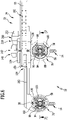
- a first fixing device 122 is provided, specifically in the form of a clamping device 124 with a first clamping element 126 and a second clamping element 127.
- the first clamping element comprises a flat plate 128 which carries the receptacle 86 on one side and on the other side two bolt-shaped connecting members 130 protruding perpendicularly from it and passing through the guide slot 118, each of which is provided with a blind hole 132 comprising an internal thread.
- the second clamping element 127 is also designed in the form of a plate 134 which has two bores 136 through which threaded shanks 138 of connecting screws pass, the threaded shanks 138 being screwed into the blind holes 132 .
- a first clamping member 142 is provided with a bolt-shaped threaded shank 144 and a T-shaped head 146.
- the threaded shank 144 passes through a bore 148 in the plate 134 and the guide slot 120 and is screwed into a threaded bore 150 of the plate 128.
- the plates 128 and 134 are pulled towards one another and clamp the base body 80 between them. Twisting the first clamping member 142 counterclockwise loosens the plates 128 and 134 just enough to allow the first locking device 122 to pivot relative to the body 80 about a pivot axis defined by the curvature of the guide slots 118 and 120 is defined. As already explained, this pivot axis ideally runs through the center point 28.
- the first clamping member 142 is designed in the form of a clamping screw 143 . This can be brought from an adjustment position in which the clamping device 124 can be moved relative to the base body 80 into a clamping position in which the clamping device 124 is immovably fixed relative to the base body 80 .
- the instrument 72 also includes a locking device 152 for locking the first coupling device 76 on the base body 80 in a basic position in which the coupling device longitudinal axes 84 and 94 of the coupling devices 76 and 78 are aligned parallel to one another.
- the locking device 152 includes a latching connection device 154 with a movable first latching member 156 and a second latching member 158, which is formed by one of the two connecting members 130.
- a latching connection device 154 with a movable first latching member 156 and a second latching member 158, which is formed by one of the two connecting members 130.
- the first and the second latching element 156, 158 are positively and/or positively engaged; in a release position they are disengaged.
- the first latching member 156 is in the form of a latching lever 162 mounted on the base body 80 such that it can pivot about a pivot axis 160 which runs parallel to the longitudinal axes of the connecting members 130 . It comprises a bore 164 through which a cylindrical bearing pin 166 which is inserted in a through bore 168 of the base body 80 passes.
- the latching lever 162 is inserted into a latching lever recess 170 and held in the basic position under prestressing, specifically with a spring element 172 in the form of a helical spring designed as a compression spring, which is inserted into a blind hole 174, the longitudinal axis of which runs transversely to the pivot axis 160, and against a proximal End of the locking lever 162 presses.
- a protruding projection 176 Arranged at the other end of latching lever 162 is a protruding projection 176, which can be brought into engagement with one connecting link 130 in the basic position, in such a way that projection 176 engages behind one connecting link 130, which in the basic position is between projection 176 and the pivot axis 160 is held.
- an actuating surface 178 which is provided with a plurality of transverse grooves on latching lever 162 and faces away from spring element 172, can be subjected to a release force that compresses spring element 172 and pivots latching lever 162 about pivot axis 160 such that the projection 176 releases the connecting member 130 which interacts with it in the basic position. Furthermore, if the first clamping device 124 is released, ie it assumes the adjustment position, the first locking device 122 can be moved in the guide slots 118 and 120 about the pivot axis of the instrument 72 .
- a display device 182 is also formed on the angle adjuster 74 . It comprises a plurality of angle markings 186 formed on a side face 184 of the base body 80 running concentrically to the pivot axis of the instrument 72 and formed in the form of flat, narrow grooves.
- An indicator member 188 is formed on the first coupler 76 in the form of a protrusion 190 protruding from the plate 128 at a side edge thereof which points to the angle markings 186 .
- a further indicator element can also be arranged or formed on the second clamping element 127 .
- an indicator element 192 corresponding to the indicator element 188 is also arranged on the plate 134 .
- the angle adjuster 74 further includes a second guide device 194 for guiding movement of the second coupling device 78 along a straight path. It is embodied or arranged on the base body 80 and comprises two guide bodies 196, each with a guide receptacle 198 embodied in the form of an opening, which define a common longitudinal axis 200.
- the two guide bodies 196 are arranged at a distance from one another on a side surface of the base body 80 which points away from the side surface with the angle markings 186 .
- the second coupling device 78 is arranged on a rod or shaft-shaped guide member 202 at one end thereof.
- the guide member 202 has a non-round, in particular polygonal, cross-section, which is designed to essentially correspond to a cross-section of the guide receptacles 198, so that the guide member 202 can be displaced parallel to the longitudinal axis 200 in the guide receptacle 198.
- Retaining ring 90 is disposed laterally on guide member 202 such that coupler longitudinal axes 84 and 94 define a common plane perpendicular to pivot axis 160 .
- the instrument 72 also includes a second fixing device 204 , which is also designed in the form of a clamping device 206 . It comprises a second clamping member 208 for clamping the guide member 202 to the base body 80.
- the second clamping member 208 is designed in the form of a clamping screw 210 which passes through a threaded bore 212 on one of the guide bodies 196 whose longitudinal axis runs transversely to the longitudinal axis 200 .
- a threaded shank 214 of the clamping screw 210 is screwed into the threaded bore 212 and presses with a free shank end 216 against the guide member 202 in the second alignment position.
- the guide member 202 has a groove-shaped guide recess 218 running parallel to the longitudinal axis 200, into which the shaft end 216 dips.
- End stops 220 which limit a displacement movement of the guide member 202 relative to the base body 80 .
- the clamping screw 210 has a T-shaped head 222, so that the shank end 216 can be moved towards the guide member 202 by turning the clamping screw 210 clockwise and away from the guide member 202 by turning it counterclockwise.
- bone screws 14 are screwed into the pedicles of the vertebrae 60 in the desired number.
- the bone screws 14 are then each coupled to an instrument 38 .
- the insertion instrument 46 is then used to insert connecting rods 34 into the rod receptacles 30 of two or more bone screws 14 in the manner described above.
- the connecting rods 34 can now be pre-fixed to a respective bone screw 14 with the screw-in instrument 50 inserted through the outer sleeve 42 .
- the connecting rod 34 is fixed to a bone screw 14 with the screw-in instrument 50 .
- the instrument 72 can now be coupled to the two instruments 38 in the manner described, as shown in FIGS figures 4 and 5 shown by sliding the couplers 76 and 78 onto the extension sleeves 104 connected to the instruments 38.
- the angle adjuster 74 is initially in the basic position, so that the longitudinal axes of the coupling device 84 and 94 are aligned parallel to one another.
- the locking lever 162 is first actuated by applying an actuating force to the actuating surface 178.
- the projection 176 then releases the connecting link 130 engaged with it and the first coupling device 76 can be pivoted relative to the second coupling device 78 or moved along the guide path defined by the first guide device 114 .
- the first locking device 122 is initially loosened and the coupling devices 76 and 78 are pivoted until the desired angle 180 can be read on the display device 182 .
- the first coupling device 76 can now be fixed in the first alignment position with the clamping device 124 .
- the clamping screw 143 is turned clockwise until the clamping device 124 clamps the base body 80 between itself.
- the first and second coupling device 76, 80 can be displaced with the second guide device 194 in the manner described relative to one another parallel to the longitudinal axis 200.
- the distractor 64 described above can be used, which can be coupled directly to the ends 40 of the instruments 38 in order to move the bone screws 14 away from one another or towards one another in a direction defined by the connecting rod 34 .
- any number of bone screws 14 can be screwed to vertebrae 60 in the manner described.
- the angle adjuster 74 can also be used to align instruments 38 relative to one another that are coupled to bone screws 14 that are fixed to the same vertebra 60 .
Landscapes
- Health & Medical Sciences (AREA)
- Orthopedic Medicine & Surgery (AREA)
- Neurology (AREA)
- Life Sciences & Earth Sciences (AREA)
- Surgery (AREA)
- Heart & Thoracic Surgery (AREA)
- Engineering & Computer Science (AREA)
- Biomedical Technology (AREA)
- Nuclear Medicine, Radiotherapy & Molecular Imaging (AREA)
- Medical Informatics (AREA)
- Molecular Biology (AREA)
- Animal Behavior & Ethology (AREA)
- General Health & Medical Sciences (AREA)
- Public Health (AREA)
- Veterinary Medicine (AREA)
- Surgical Instruments (AREA)
Applications Claiming Priority (2)
| Application Number | Priority Date | Filing Date | Title |
|---|---|---|---|
| DE102015120955.1A DE102015120955A1 (de) | 2015-12-02 | 2015-12-02 | Medizinisches Instrument und medizinisches Instrumentarium |
| PCT/EP2016/079616 WO2017093497A1 (de) | 2015-12-02 | 2016-12-02 | Medizinisches instrument und medizinisches instrumentarium |
Publications (2)
| Publication Number | Publication Date |
|---|---|
| EP3383291A1 EP3383291A1 (de) | 2018-10-10 |
| EP3383291B1 true EP3383291B1 (de) | 2022-06-22 |
Family
ID=57460540
Family Applications (1)
| Application Number | Title | Priority Date | Filing Date |
|---|---|---|---|
| EP16805150.6A Active EP3383291B1 (de) | 2015-12-02 | 2016-12-02 | Medizinisches instrument und medizinisches instrumentarium |
Country Status (6)
| Country | Link |
|---|---|
| US (1) | US10588673B2 (enExample) |
| EP (1) | EP3383291B1 (enExample) |
| JP (1) | JP6863986B2 (enExample) |
| CN (1) | CN108697443B (enExample) |
| DE (1) | DE102015120955A1 (enExample) |
| WO (1) | WO2017093497A1 (enExample) |
Families Citing this family (8)
| Publication number | Priority date | Publication date | Assignee | Title |
|---|---|---|---|---|
| WO2012128825A1 (en) * | 2011-03-24 | 2012-09-27 | Jackson Roger P | Polyaxial bone anchor with compound articulation and pop-on shank |
| US11484349B2 (en) * | 2017-02-17 | 2022-11-01 | Warsaw Orthopedic, Inc. | Surgical system and method |
| WO2019046443A1 (en) | 2017-08-30 | 2019-03-07 | Zimmer Biomet Spine, Inc. | DYNAMIC STABILIZATION SYSTEM |
| CN107736925B (zh) * | 2017-11-14 | 2020-03-24 | 山东威高骨科材料股份有限公司 | 套筒、用于安装连接棒的辅助装置及连接棒的安装方法 |
| EP3517062B1 (en) | 2018-01-26 | 2021-03-17 | Aesculap AG | Spinal repositioning instrument and spinal repositioning system |
| EP3636185B1 (en) * | 2018-10-09 | 2023-12-06 | Biedermann Technologies GmbH & Co. KG | System for correcting the position of bones, bone parts or vertebrae |
| US11678912B2 (en) * | 2019-09-24 | 2023-06-20 | Astura Medical Inc | Minimally invasive compressor / distractor |
| CN117179869A (zh) * | 2022-06-01 | 2023-12-08 | 硕果生医科技有限公司 | 骨钉套件 |
Family Cites Families (16)
| Publication number | Priority date | Publication date | Assignee | Title |
|---|---|---|---|---|
| CN2074630U (zh) * | 1990-10-10 | 1991-04-10 | 黄克勤 | 单臂式桥架骨折弹性外固定器 |
| CN2406623Y (zh) * | 2000-01-27 | 2000-11-22 | 陈国强 | 多功能颅脑立体定向手术装置 |
| US20080077155A1 (en) * | 2006-09-25 | 2008-03-27 | Jennifer Diederich | System and method for displacement of bony structures |
| US8197488B2 (en) * | 2006-10-16 | 2012-06-12 | Depuy Spine, Inc. | Automatic locking casper distractor |
| CN201029934Y (zh) * | 2007-01-24 | 2008-03-05 | 辛兆芹 | 微波刀机械引导臂 |
| CN101791249B (zh) * | 2010-01-28 | 2012-09-26 | 韩增灿 | 侧脑室前角穿刺定向仪 |
| US9345547B2 (en) * | 2011-04-18 | 2016-05-24 | Warsaw Orthopedic, Inc. | Apparatus and method for sizing a connecting element for positioning along a bone structure |
| TWI448790B (zh) * | 2011-05-13 | 2014-08-11 | Chi Mei Corp | 液晶配向膜及液晶顯示元件 |
| US8951257B2 (en) * | 2012-02-15 | 2015-02-10 | Warsaw Orthopedic, Inc. | Spinal correction system and method |
| US8906034B2 (en) * | 2012-04-17 | 2014-12-09 | Alphatec Spine, Inc. | Instrument and method for spinal compression and distraction |
| DE102012107056A1 (de) | 2012-08-01 | 2014-05-15 | Aesculap Ag | Chirurgisches Instrumentarium |
| US20140107659A1 (en) * | 2012-10-12 | 2014-04-17 | Alphatec Spine, Inc. | In situ rod measuring instrument and method of use |
| CN203369957U (zh) * | 2013-07-19 | 2014-01-01 | 马台 | 股骨头中心导航器 |
| DE102013108362A1 (de) * | 2013-08-02 | 2015-02-05 | Aesculap Ag | Medizinisches Instrument zum Halten und Handhaben eines chirurgischen Befestigungselements und Wirbelsäulenstabilisierungssystem |
| US9402660B2 (en) * | 2013-09-05 | 2016-08-02 | Warsaw Orthopedic, Inc. | Surgical instrument and method |
| DE102013111683A1 (de) | 2013-10-23 | 2015-04-23 | Aesculap Ag | Wirbelsäulenstabilisierungsystem, medizinisches Instrumentarium und medizinische Vorrichtung zum parallelen Ausrichten medizinischer Instrumente |
-
2015
- 2015-12-02 DE DE102015120955.1A patent/DE102015120955A1/de not_active Withdrawn
-
2016
- 2016-12-02 EP EP16805150.6A patent/EP3383291B1/de active Active
- 2016-12-02 JP JP2018528693A patent/JP6863986B2/ja active Active
- 2016-12-02 CN CN201680071130.1A patent/CN108697443B/zh active Active
- 2016-12-02 WO PCT/EP2016/079616 patent/WO2017093497A1/de not_active Ceased
-
2018
- 2018-05-29 US US15/990,966 patent/US10588673B2/en active Active
Also Published As
| Publication number | Publication date |
|---|---|
| CN108697443A (zh) | 2018-10-23 |
| EP3383291A1 (de) | 2018-10-10 |
| JP2018537195A (ja) | 2018-12-20 |
| US20180271566A1 (en) | 2018-09-27 |
| US10588673B2 (en) | 2020-03-17 |
| DE102015120955A1 (de) | 2017-06-08 |
| JP6863986B2 (ja) | 2021-04-21 |
| WO2017093497A1 (de) | 2017-06-08 |
| CN108697443B (zh) | 2021-12-21 |
Similar Documents
| Publication | Publication Date | Title |
|---|---|---|
| EP3383291B1 (de) | Medizinisches instrument und medizinisches instrumentarium | |
| EP3454767B1 (de) | Medizintechnisches instrument zur provisorischen fixierung einer polyaxialen pedikelschraube | |
| EP2832308B1 (de) | Medizinisches Instrument zum Halten und Handhaben eines chirurgischen Befestigungselements und Wirbelsäulenstabilisierungssystem | |
| DE69723108T2 (de) | Regulierbare osteosynthesevorrichtung für die wirbelsäule und positionierungswerkzeug | |
| EP2266483B1 (de) | Chirurgische Knochenverankerungsvorrichtung und Wirbelsäulenfixationssystem | |
| EP2233097B1 (de) | Instrumentensatz zum Einsetzen eines Stabilisierungssystems in die Wirbelsäule eines Körpers | |
| EP3023065B1 (de) | Pedikelschraubensystem und wirbelsäulenstabilisierungssystem | |
| DE69905707T2 (de) | Wirbelsäulen-osteosynthesesystem mit spannvorrichtung, insbesondere zur vorderen fixierung | |
| WO2004021901A1 (de) | Orthopädische fixationseinrichtung | |
| EP3117787A1 (de) | Pedikelschraube mit tulpe | |
| EP2829244A2 (de) | Instrumentensatz für die perkutane Wirbelsäulenstabilisierung mit Hilfe von Pedikelschrauben und Stäben | |
| EP3075330B1 (de) | Medizinische führungsvorrichtung | |
| EP2460481A1 (de) | Fusionsimplantat für Facettengelenke | |
| EP1408859A1 (de) | Verbindungselement | |
| EP3035877B1 (de) | Chirurgisches instrument zum manipulieren, positionieren und fixieren eines chirurgischen stabes relativ zu einem implantat | |
| EP3023066B1 (de) | Pedikelschraubensystem und wirbelsäulenstabilisierungssystem | |
| DE102022108980A1 (de) | Osteosynthesevorrichtung insbesondere zur Wirbelsäulenbehandlung und Befestigungssystem für diese | |
| EP3592253B1 (de) | Medizinisches sägeschablonensystem | |
| EP4478971A1 (de) | Knochenklemme | |
| EP4051143B1 (de) | Medizintechnisches entkopplungsinstrument | |
| DE20213572U1 (de) | Orthopädische Fixationseinrichtung | |
| DE102024109618A1 (de) | Hülse für eine Implantatschraube und Implantatschraube mit einer Hülse | |
| EP4620413A1 (de) | Medizinisches instrument zur wirbelmanipulation | |
| DE102024108234A1 (de) | Medizinisches Instrument zur Wirbelmanipulation | |
| EP4563103A1 (de) | Zentriereinheit mit verriegelungsschraube |
Legal Events
| Date | Code | Title | Description |
|---|---|---|---|
| STAA | Information on the status of an ep patent application or granted ep patent |
Free format text: STATUS: UNKNOWN |
|
| STAA | Information on the status of an ep patent application or granted ep patent |
Free format text: STATUS: THE INTERNATIONAL PUBLICATION HAS BEEN MADE |
|
| PUAI | Public reference made under article 153(3) epc to a published international application that has entered the european phase |
Free format text: ORIGINAL CODE: 0009012 |
|
| STAA | Information on the status of an ep patent application or granted ep patent |
Free format text: STATUS: REQUEST FOR EXAMINATION WAS MADE |
|
| 17P | Request for examination filed |
Effective date: 20180629 |
|
| AK | Designated contracting states |
Kind code of ref document: A1 Designated state(s): AL AT BE BG CH CY CZ DE DK EE ES FI FR GB GR HR HU IE IS IT LI LT LU LV MC MK MT NL NO PL PT RO RS SE SI SK SM TR |
|
| AX | Request for extension of the european patent |
Extension state: BA ME |
|
| DAV | Request for validation of the european patent (deleted) | ||
| DAX | Request for extension of the european patent (deleted) | ||
| GRAP | Despatch of communication of intention to grant a patent |
Free format text: ORIGINAL CODE: EPIDOSNIGR1 |
|
| STAA | Information on the status of an ep patent application or granted ep patent |
Free format text: STATUS: GRANT OF PATENT IS INTENDED |
|
| INTG | Intention to grant announced |
Effective date: 20220110 |
|
| GRAS | Grant fee paid |
Free format text: ORIGINAL CODE: EPIDOSNIGR3 |
|
| GRAA | (expected) grant |
Free format text: ORIGINAL CODE: 0009210 |
|
| STAA | Information on the status of an ep patent application or granted ep patent |
Free format text: STATUS: THE PATENT HAS BEEN GRANTED |
|
| AK | Designated contracting states |
Kind code of ref document: B1 Designated state(s): AL AT BE BG CH CY CZ DE DK EE ES FI FR GB GR HR HU IE IS IT LI LT LU LV MC MK MT NL NO PL PT RO RS SE SI SK SM TR |
|
| REG | Reference to a national code |
Ref country code: GB Ref legal event code: FG4D Free format text: NOT ENGLISH |
|
| REG | Reference to a national code |
Ref country code: CH Ref legal event code: EP |
|
| REG | Reference to a national code |
Ref country code: DE Ref legal event code: R096 Ref document number: 502016014998 Country of ref document: DE |
|
| REG | Reference to a national code |
Ref country code: AT Ref legal event code: REF Ref document number: 1499282 Country of ref document: AT Kind code of ref document: T Effective date: 20220715 |
|
| REG | Reference to a national code |
Ref country code: IE Ref legal event code: FG4D Free format text: LANGUAGE OF EP DOCUMENT: GERMAN |
|
| REG | Reference to a national code |
Ref country code: LT Ref legal event code: MG9D |
|
| REG | Reference to a national code |
Ref country code: NL Ref legal event code: MP Effective date: 20220622 |
|
| PG25 | Lapsed in a contracting state [announced via postgrant information from national office to epo] |
Ref country code: SE Free format text: LAPSE BECAUSE OF FAILURE TO SUBMIT A TRANSLATION OF THE DESCRIPTION OR TO PAY THE FEE WITHIN THE PRESCRIBED TIME-LIMIT Effective date: 20220622 Ref country code: NO Free format text: LAPSE BECAUSE OF FAILURE TO SUBMIT A TRANSLATION OF THE DESCRIPTION OR TO PAY THE FEE WITHIN THE PRESCRIBED TIME-LIMIT Effective date: 20220922 Ref country code: LT Free format text: LAPSE BECAUSE OF FAILURE TO SUBMIT A TRANSLATION OF THE DESCRIPTION OR TO PAY THE FEE WITHIN THE PRESCRIBED TIME-LIMIT Effective date: 20220622 Ref country code: HR Free format text: LAPSE BECAUSE OF FAILURE TO SUBMIT A TRANSLATION OF THE DESCRIPTION OR TO PAY THE FEE WITHIN THE PRESCRIBED TIME-LIMIT Effective date: 20220622 Ref country code: GR Free format text: LAPSE BECAUSE OF FAILURE TO SUBMIT A TRANSLATION OF THE DESCRIPTION OR TO PAY THE FEE WITHIN THE PRESCRIBED TIME-LIMIT Effective date: 20220923 Ref country code: FI Free format text: LAPSE BECAUSE OF FAILURE TO SUBMIT A TRANSLATION OF THE DESCRIPTION OR TO PAY THE FEE WITHIN THE PRESCRIBED TIME-LIMIT Effective date: 20220622 Ref country code: BG Free format text: LAPSE BECAUSE OF FAILURE TO SUBMIT A TRANSLATION OF THE DESCRIPTION OR TO PAY THE FEE WITHIN THE PRESCRIBED TIME-LIMIT Effective date: 20220922 |
|
| PG25 | Lapsed in a contracting state [announced via postgrant information from national office to epo] |
Ref country code: RS Free format text: LAPSE BECAUSE OF FAILURE TO SUBMIT A TRANSLATION OF THE DESCRIPTION OR TO PAY THE FEE WITHIN THE PRESCRIBED TIME-LIMIT Effective date: 20220622 Ref country code: LV Free format text: LAPSE BECAUSE OF FAILURE TO SUBMIT A TRANSLATION OF THE DESCRIPTION OR TO PAY THE FEE WITHIN THE PRESCRIBED TIME-LIMIT Effective date: 20220622 |
|
| PG25 | Lapsed in a contracting state [announced via postgrant information from national office to epo] |
Ref country code: NL Free format text: LAPSE BECAUSE OF FAILURE TO SUBMIT A TRANSLATION OF THE DESCRIPTION OR TO PAY THE FEE WITHIN THE PRESCRIBED TIME-LIMIT Effective date: 20220622 |
|
| PG25 | Lapsed in a contracting state [announced via postgrant information from national office to epo] |
Ref country code: SM Free format text: LAPSE BECAUSE OF FAILURE TO SUBMIT A TRANSLATION OF THE DESCRIPTION OR TO PAY THE FEE WITHIN THE PRESCRIBED TIME-LIMIT Effective date: 20220622 Ref country code: SK Free format text: LAPSE BECAUSE OF FAILURE TO SUBMIT A TRANSLATION OF THE DESCRIPTION OR TO PAY THE FEE WITHIN THE PRESCRIBED TIME-LIMIT Effective date: 20220622 Ref country code: RO Free format text: LAPSE BECAUSE OF FAILURE TO SUBMIT A TRANSLATION OF THE DESCRIPTION OR TO PAY THE FEE WITHIN THE PRESCRIBED TIME-LIMIT Effective date: 20220622 Ref country code: PT Free format text: LAPSE BECAUSE OF FAILURE TO SUBMIT A TRANSLATION OF THE DESCRIPTION OR TO PAY THE FEE WITHIN THE PRESCRIBED TIME-LIMIT Effective date: 20221024 Ref country code: ES Free format text: LAPSE BECAUSE OF FAILURE TO SUBMIT A TRANSLATION OF THE DESCRIPTION OR TO PAY THE FEE WITHIN THE PRESCRIBED TIME-LIMIT Effective date: 20220622 Ref country code: EE Free format text: LAPSE BECAUSE OF FAILURE TO SUBMIT A TRANSLATION OF THE DESCRIPTION OR TO PAY THE FEE WITHIN THE PRESCRIBED TIME-LIMIT Effective date: 20220622 Ref country code: CZ Free format text: LAPSE BECAUSE OF FAILURE TO SUBMIT A TRANSLATION OF THE DESCRIPTION OR TO PAY THE FEE WITHIN THE PRESCRIBED TIME-LIMIT Effective date: 20220622 |
|
| PG25 | Lapsed in a contracting state [announced via postgrant information from national office to epo] |
Ref country code: PL Free format text: LAPSE BECAUSE OF FAILURE TO SUBMIT A TRANSLATION OF THE DESCRIPTION OR TO PAY THE FEE WITHIN THE PRESCRIBED TIME-LIMIT Effective date: 20220622 Ref country code: IS Free format text: LAPSE BECAUSE OF FAILURE TO SUBMIT A TRANSLATION OF THE DESCRIPTION OR TO PAY THE FEE WITHIN THE PRESCRIBED TIME-LIMIT Effective date: 20221022 |
|
| REG | Reference to a national code |
Ref country code: DE Ref legal event code: R097 Ref document number: 502016014998 Country of ref document: DE |
|
| PG25 | Lapsed in a contracting state [announced via postgrant information from national office to epo] |
Ref country code: AL Free format text: LAPSE BECAUSE OF FAILURE TO SUBMIT A TRANSLATION OF THE DESCRIPTION OR TO PAY THE FEE WITHIN THE PRESCRIBED TIME-LIMIT Effective date: 20220622 |
|
| PG25 | Lapsed in a contracting state [announced via postgrant information from national office to epo] |
Ref country code: DK Free format text: LAPSE BECAUSE OF FAILURE TO SUBMIT A TRANSLATION OF THE DESCRIPTION OR TO PAY THE FEE WITHIN THE PRESCRIBED TIME-LIMIT Effective date: 20220622 |
|
| PLBE | No opposition filed within time limit |
Free format text: ORIGINAL CODE: 0009261 |
|
| STAA | Information on the status of an ep patent application or granted ep patent |
Free format text: STATUS: NO OPPOSITION FILED WITHIN TIME LIMIT |
|
| 26N | No opposition filed |
Effective date: 20230323 |
|
| REG | Reference to a national code |
Ref country code: CH Ref legal event code: PL |
|
| REG | Reference to a national code |
Ref country code: BE Ref legal event code: MM Effective date: 20221231 |
|
| PG25 | Lapsed in a contracting state [announced via postgrant information from national office to epo] |
Ref country code: SI Free format text: LAPSE BECAUSE OF FAILURE TO SUBMIT A TRANSLATION OF THE DESCRIPTION OR TO PAY THE FEE WITHIN THE PRESCRIBED TIME-LIMIT Effective date: 20220622 Ref country code: LU Free format text: LAPSE BECAUSE OF NON-PAYMENT OF DUE FEES Effective date: 20221202 |
|
| P01 | Opt-out of the competence of the unified patent court (upc) registered |
Effective date: 20230807 |
|
| PG25 | Lapsed in a contracting state [announced via postgrant information from national office to epo] |
Ref country code: LI Free format text: LAPSE BECAUSE OF NON-PAYMENT OF DUE FEES Effective date: 20221231 Ref country code: IE Free format text: LAPSE BECAUSE OF NON-PAYMENT OF DUE FEES Effective date: 20221202 Ref country code: CH Free format text: LAPSE BECAUSE OF NON-PAYMENT OF DUE FEES Effective date: 20221231 |
|
| PG25 | Lapsed in a contracting state [announced via postgrant information from national office to epo] |
Ref country code: BE Free format text: LAPSE BECAUSE OF NON-PAYMENT OF DUE FEES Effective date: 20221231 |
|
| PG25 | Lapsed in a contracting state [announced via postgrant information from national office to epo] |
Ref country code: IT Free format text: LAPSE BECAUSE OF FAILURE TO SUBMIT A TRANSLATION OF THE DESCRIPTION OR TO PAY THE FEE WITHIN THE PRESCRIBED TIME-LIMIT Effective date: 20220622 |
|
| REG | Reference to a national code |
Ref country code: AT Ref legal event code: MM01 Ref document number: 1499282 Country of ref document: AT Kind code of ref document: T Effective date: 20221202 |
|
| PG25 | Lapsed in a contracting state [announced via postgrant information from national office to epo] |
Ref country code: HU Free format text: LAPSE BECAUSE OF FAILURE TO SUBMIT A TRANSLATION OF THE DESCRIPTION OR TO PAY THE FEE WITHIN THE PRESCRIBED TIME-LIMIT; INVALID AB INITIO Effective date: 20161202 |
|
| PG25 | Lapsed in a contracting state [announced via postgrant information from national office to epo] |
Ref country code: AT Free format text: LAPSE BECAUSE OF NON-PAYMENT OF DUE FEES Effective date: 20221202 |
|
| PG25 | Lapsed in a contracting state [announced via postgrant information from national office to epo] |
Ref country code: CY Free format text: LAPSE BECAUSE OF FAILURE TO SUBMIT A TRANSLATION OF THE DESCRIPTION OR TO PAY THE FEE WITHIN THE PRESCRIBED TIME-LIMIT Effective date: 20220622 Ref country code: AT Free format text: LAPSE BECAUSE OF NON-PAYMENT OF DUE FEES Effective date: 20221202 |
|
| PG25 | Lapsed in a contracting state [announced via postgrant information from national office to epo] |
Ref country code: MK Free format text: LAPSE BECAUSE OF FAILURE TO SUBMIT A TRANSLATION OF THE DESCRIPTION OR TO PAY THE FEE WITHIN THE PRESCRIBED TIME-LIMIT Effective date: 20220622 |
|
| PG25 | Lapsed in a contracting state [announced via postgrant information from national office to epo] |
Ref country code: MC Free format text: LAPSE BECAUSE OF FAILURE TO SUBMIT A TRANSLATION OF THE DESCRIPTION OR TO PAY THE FEE WITHIN THE PRESCRIBED TIME-LIMIT Effective date: 20220622 |
|
| PG25 | Lapsed in a contracting state [announced via postgrant information from national office to epo] |
Ref country code: MC Free format text: LAPSE BECAUSE OF FAILURE TO SUBMIT A TRANSLATION OF THE DESCRIPTION OR TO PAY THE FEE WITHIN THE PRESCRIBED TIME-LIMIT Effective date: 20220622 |
|
| PG25 | Lapsed in a contracting state [announced via postgrant information from national office to epo] |
Ref country code: MT Free format text: LAPSE BECAUSE OF FAILURE TO SUBMIT A TRANSLATION OF THE DESCRIPTION OR TO PAY THE FEE WITHIN THE PRESCRIBED TIME-LIMIT Effective date: 20220622 |
|
| PG25 | Lapsed in a contracting state [announced via postgrant information from national office to epo] |
Ref country code: BG Free format text: LAPSE BECAUSE OF FAILURE TO SUBMIT A TRANSLATION OF THE DESCRIPTION OR TO PAY THE FEE WITHIN THE PRESCRIBED TIME-LIMIT Effective date: 20220622 |
|
| PG25 | Lapsed in a contracting state [announced via postgrant information from national office to epo] |
Ref country code: BG Free format text: LAPSE BECAUSE OF FAILURE TO SUBMIT A TRANSLATION OF THE DESCRIPTION OR TO PAY THE FEE WITHIN THE PRESCRIBED TIME-LIMIT Effective date: 20220622 |
|
| PGFP | Annual fee paid to national office [announced via postgrant information from national office to epo] |
Ref country code: DE Payment date: 20241216 Year of fee payment: 9 |
|
| PGFP | Annual fee paid to national office [announced via postgrant information from national office to epo] |
Ref country code: GB Payment date: 20241218 Year of fee payment: 9 |
|
| PGFP | Annual fee paid to national office [announced via postgrant information from national office to epo] |
Ref country code: FR Payment date: 20241218 Year of fee payment: 9 |
|
| PG25 | Lapsed in a contracting state [announced via postgrant information from national office to epo] |
Ref country code: TR Free format text: LAPSE BECAUSE OF FAILURE TO SUBMIT A TRANSLATION OF THE DESCRIPTION OR TO PAY THE FEE WITHIN THE PRESCRIBED TIME-LIMIT Effective date: 20220622 |