EP3023065B1 - Pedikelschraubensystem und wirbelsäulenstabilisierungssystem - Google Patents
Pedikelschraubensystem und wirbelsäulenstabilisierungssystem Download PDFInfo
- Publication number
- EP3023065B1 EP3023065B1 EP15195764.4A EP15195764A EP3023065B1 EP 3023065 B1 EP3023065 B1 EP 3023065B1 EP 15195764 A EP15195764 A EP 15195764A EP 3023065 B1 EP3023065 B1 EP 3023065B1
- Authority
- EP
- European Patent Office
- Prior art keywords
- screw
- coupling
- pedicle screw
- screw shaft
- bone
- Prior art date
- Legal status (The legal status is an assumption and is not a legal conclusion. Google has not performed a legal analysis and makes no representation as to the accuracy of the status listed.)
- Active
Links
- 230000008878 coupling Effects 0.000 claims description 109
- 238000010168 coupling process Methods 0.000 claims description 109
- 238000005859 coupling reaction Methods 0.000 claims description 109
- 210000000988 bone and bone Anatomy 0.000 claims description 106
- 241000309551 Arthraxon hispidus Species 0.000 claims description 23
- 230000006641 stabilisation Effects 0.000 claims description 13
- 238000011105 stabilization Methods 0.000 claims description 13
- 238000004026 adhesive bonding Methods 0.000 claims 1
- 238000005476 soldering Methods 0.000 claims 1
- 239000000126 substance Substances 0.000 claims 1
- 238000003466 welding Methods 0.000 claims 1
- 238000003780 insertion Methods 0.000 description 18
- 230000037431 insertion Effects 0.000 description 18
- 230000000903 blocking effect Effects 0.000 description 5
- 238000013461 design Methods 0.000 description 5
- 230000005540 biological transmission Effects 0.000 description 2
- 230000002349 favourable effect Effects 0.000 description 2
- 238000004519 manufacturing process Methods 0.000 description 2
- 241000722921 Tulipa gesneriana Species 0.000 description 1
- 230000009471 action Effects 0.000 description 1
- 230000015572 biosynthetic process Effects 0.000 description 1
- 238000005266 casting Methods 0.000 description 1
- 238000012937 correction Methods 0.000 description 1
- 230000001419 dependent effect Effects 0.000 description 1
- 238000011161 development Methods 0.000 description 1
- 238000005553 drilling Methods 0.000 description 1
- 230000000694 effects Effects 0.000 description 1
- 238000002513 implantation Methods 0.000 description 1
- 238000003754 machining Methods 0.000 description 1
- 238000000034 method Methods 0.000 description 1
- 230000009467 reduction Effects 0.000 description 1
- 230000000717 retained effect Effects 0.000 description 1
- 238000010079 rubber tapping Methods 0.000 description 1
- 238000007493 shaping process Methods 0.000 description 1
- 238000011477 surgical intervention Methods 0.000 description 1
Images

Classifications
-
- A—HUMAN NECESSITIES
- A61—MEDICAL OR VETERINARY SCIENCE; HYGIENE
- A61B—DIAGNOSIS; SURGERY; IDENTIFICATION
- A61B17/00—Surgical instruments, devices or methods, e.g. tourniquets
- A61B17/56—Surgical instruments or methods for treatment of bones or joints; Devices specially adapted therefor
- A61B17/58—Surgical instruments or methods for treatment of bones or joints; Devices specially adapted therefor for osteosynthesis, e.g. bone plates, screws, setting implements or the like
- A61B17/68—Internal fixation devices, including fasteners and spinal fixators, even if a part thereof projects from the skin
- A61B17/70—Spinal positioners or stabilisers ; Bone stabilisers comprising fluid filler in an implant
- A61B17/7001—Screws or hooks combined with longitudinal elements which do not contact vertebrae
- A61B17/7035—Screws or hooks, wherein a rod-clamping part and a bone-anchoring part can pivot relative to each other
- A61B17/7037—Screws or hooks, wherein a rod-clamping part and a bone-anchoring part can pivot relative to each other wherein pivoting is blocked when the rod is clamped
-
- A—HUMAN NECESSITIES
- A61—MEDICAL OR VETERINARY SCIENCE; HYGIENE
- A61B—DIAGNOSIS; SURGERY; IDENTIFICATION
- A61B17/00—Surgical instruments, devices or methods, e.g. tourniquets
- A61B17/56—Surgical instruments or methods for treatment of bones or joints; Devices specially adapted therefor
- A61B17/58—Surgical instruments or methods for treatment of bones or joints; Devices specially adapted therefor for osteosynthesis, e.g. bone plates, screws, setting implements or the like
- A61B17/68—Internal fixation devices, including fasteners and spinal fixators, even if a part thereof projects from the skin
- A61B17/70—Spinal positioners or stabilisers ; Bone stabilisers comprising fluid filler in an implant
- A61B17/7074—Tools specially adapted for spinal fixation operations other than for bone removal or filler handling
- A61B17/7076—Tools specially adapted for spinal fixation operations other than for bone removal or filler handling for driving, positioning or assembling spinal clamps or bone anchors specially adapted for spinal fixation
- A61B17/7077—Tools specially adapted for spinal fixation operations other than for bone removal or filler handling for driving, positioning or assembling spinal clamps or bone anchors specially adapted for spinal fixation for moving bone anchors attached to vertebrae, thereby displacing the vertebrae
-
- A—HUMAN NECESSITIES
- A61—MEDICAL OR VETERINARY SCIENCE; HYGIENE
- A61B—DIAGNOSIS; SURGERY; IDENTIFICATION
- A61B17/00—Surgical instruments, devices or methods, e.g. tourniquets
- A61B17/56—Surgical instruments or methods for treatment of bones or joints; Devices specially adapted therefor
- A61B17/58—Surgical instruments or methods for treatment of bones or joints; Devices specially adapted therefor for osteosynthesis, e.g. bone plates, screws, setting implements or the like
- A61B17/68—Internal fixation devices, including fasteners and spinal fixators, even if a part thereof projects from the skin
- A61B17/70—Spinal positioners or stabilisers ; Bone stabilisers comprising fluid filler in an implant
- A61B17/7001—Screws or hooks combined with longitudinal elements which do not contact vertebrae
- A61B17/7032—Screws or hooks with U-shaped head or back through which longitudinal rods pass
-
- A—HUMAN NECESSITIES
- A61—MEDICAL OR VETERINARY SCIENCE; HYGIENE
- A61B—DIAGNOSIS; SURGERY; IDENTIFICATION
- A61B17/00—Surgical instruments, devices or methods, e.g. tourniquets
- A61B17/56—Surgical instruments or methods for treatment of bones or joints; Devices specially adapted therefor
- A61B17/58—Surgical instruments or methods for treatment of bones or joints; Devices specially adapted therefor for osteosynthesis, e.g. bone plates, screws, setting implements or the like
- A61B17/68—Internal fixation devices, including fasteners and spinal fixators, even if a part thereof projects from the skin
- A61B17/70—Spinal positioners or stabilisers ; Bone stabilisers comprising fluid filler in an implant
- A61B17/7001—Screws or hooks combined with longitudinal elements which do not contact vertebrae
- A61B17/7035—Screws or hooks, wherein a rod-clamping part and a bone-anchoring part can pivot relative to each other
Definitions
- the present invention relates to a pedicle screw system comprising a pedicle screw with a screw shaft which has an external thread and a screw head mounted on the screw shaft in a ball joint, which screw head comprises a connecting element receptacle for a connecting element of a spinal column stabilization system.
- the present invention further relates to a spinal column stabilization system comprising at least two bone screws and at least one connecting element that can be fixed to the at least two bone screws.
- Pedicle screws and spinal column stabilization systems of the type described above are, for example, from DE 10 2013 100 574 A1 known. They can be used, for example, in deformity operations to bring deformed spinal columns into a desired shape and fix them in place by appropriate implantation and alignment of pedicle screws. To align individual, misaligned vertebrae, the forces for the corrective maneuvers are introduced into the respective vertebra via the pedicle screws.
- a pedicle screw system of the type described at the outset in that it comprises a bone alignment device and a coupling device for non-positive and / or positive coupling of the bone alignment device and the pedicle screw in an alignment position in which a mobility of the screw head and the screw shaft of three Degrees of freedom of movement of the rotation of the screw head mounted in a ball joint on the screw shaft is reduced by at least one degree of freedom of rotation, namely from originally three degrees of freedom of movement of rotation to one or two degrees of freedom of movement of rotation, wherein the screw head has a contact surface pointing in the direction of the external thread, on which the bone alignment device is supported in the alignment position.
- the further development proposed according to the invention enables the surgeon in particular to use the bone alignment device to apply forces to move, in particular rotating, to initiate deformed vertebrae of a spinal column directly on the screw shaft when the coupling device of the pedicle screw system assumes the alignment position.
- the proposed pedicle screw system thus combines on the one hand the advantages of polyaxial screws, which allow any orientation of the screw head relative to the screw shaft in order to facilitate the insertion of the connecting element into the connecting element receptacle on the screw head, and on the other hand, especially when restricting the degrees of freedom of movement of the rotation to one degree of freedom of rotation, the advantages of a monoaxial screw, which enables forces to be applied to the screw shaft to align a vertebral body into which the pedicle screw is screwed.
- the number of the originally three degrees of freedom of movement of the rotation can be limited to one or two degrees of freedom of movement of the rotation.
- the screw head has a contact surface facing in the direction of the external thread, on which the bone alignment device is supported in the alignment position. This embodiment enables in particular a direct force transmission from the bone alignment device to the screw head or a direct action on the screw head to block at least two degrees of freedom of rotation of the screw head which interacts with the screw shaft in a ball-and-socket manner.
- the coupling of the pedicle screw and the bone alignment device in the alignment position reduces the number of degrees of freedom of movement between the screw shaft and screw head to one degree of freedom of movement for rotation. This corresponds to a rotation of the screw shaft and the screw head relative to one another about only a single pivot axis.
- the coupling device can in particular provide an axial and / or rotationally fixed connection between the bone alignment device and the pedicle screw produced and thus an indirect force transmission, for example, from the bone alignment device to the screw shaft can be made possible via the bone alignment device.
- the bone alignment device is designed in the form of a clamping plate or comprises a clamping plate.
- the clamping plate on the pedicle screw can be clamped between the screw head and the external thread in order to partially block free rotation of the screw head relative to the screw shaft and only allow a pivoting movement about a single pivot axis, as is the case with a monoaxial screw allow.
- the coupling device comprises first and second coupling elements which in the alignment position are frictionally and / or positively engaged and are arranged or formed on the one hand on the bone alignment device and on the other hand on the pedicle screw.
- the bone alignment device can be brought into engagement with the pedicle screw in a simple and secure manner.
- the first coupling element is preferably designed in the form of a coupling projection and the second coupling element in the form of a coupling receptacle corresponding to the coupling projection.
- Such coupling elements can be designed in a simple manner and optionally arranged or designed on the pedicle screw or on the bone alignment device.
- the coupling projection engages positively or essentially positively in the coupling receptacle in the alignment position.
- a particularly stable pedicle screw system can be obtained, in particular, in that the coupling projection is formed in one piece with the screw shaft.
- the pedicle screw system can be produced in a particularly simple manner if the coupling projection is designed in the form of a thread-free shaft section of the screw shaft.
- the thread-free shaft section can in particular have a circular cross section or a non-circular cross section, for example in the form of an oval, a polygon or a polygon.
- a rotation between the bone alignment device and the pedicle screw can be made possible, or a non-rotatable connection with a non-circular cross section can also be established.
- the screw shank has a joint head and that the screw head has a joint head receptacle corresponding to the joint head for forming a ball joint in cooperation with the joint head.
- a ball joint can thus be formed in a simple manner by the joint head in cooperation with the joint head receptacle.
- the joint head can in particular have the shape of a sphere or part of a sphere.
- the joint head receptacle can in particular be shaped in the form of a hollow spherical seat corresponding to a joint ball.
- Degrees of freedom of rotation between the screw head and the screw shaft can be switched off in a simple manner if the coupling projection is arranged between the external thread and the joint head.
- a movement of the screw head relative to the screw shaft can be blocked in a simple manner with the bone alignment device, for example by means of a clamping connection.
- the coupling device comprises a stop element on which the bone alignment device is supported in the alignment position.
- the stop element can be formed on the screw shaft so that the bone alignment device can be supported on the one hand on the stop element and on the other hand on the screw head.
- the bone alignment device advantageously has a stop element contact surface, which in the alignment position rests on the stop element. This makes it possible in particular for the bone alignment device to be supported directly on the stop element in the alignment position. If, on the other hand, the bone alignment device can be supported on the screw head, mobility of the screw head relative to the screw shaft can be restricted in a simple manner.
- the stop element contact surface is preferably flat or essentially flat. This embodiment enables, in particular, a flat contact with the stop element if it has a flat or substantially flat stop surface against which the stop element contact surface is in contact in the alignment position.
- the stop element has a flat or essentially flat stop surface on which the bone alignment device is supported in the alignment position.
- a stop surface can be designed in a simple manner and enables the bone alignment device to rest flat on the stop element if the stop element contact surface is flat or essentially flat.
- a particularly compact design of the pedicle screw system can be achieved in particular in that the stop element is arranged or formed on the screw shaft.
- the screw shank can be manufactured particularly easily if the stop element is designed in the form of an annular flange.
- the screw shaft can be produced by casting or machining.
- the stop element is formed in one piece with the screw shank or is connected to the screw shank in a non-positive and / or material fit.
- the stop element can be pressed, glued, soldered or welded to the screw shaft.
- it can optionally be advantageous to form the stop element in one piece with the screw shaft or to connect it to it in a non-positive and / or material fit.
- an outer diameter of the stop element is greater than a maximum outer diameter of the external thread. It can thus be ensured that in the alignment position the bone alignment device cannot come into contact with the external thread.
- the stop element directly adjoins the external thread.
- the screw shaft can be screwed into a bone up to the stop element.
- the screw head can be produced in a particularly simple manner if the contact surface is designed to be flat or essentially flat or with a concave curve pointing away from the screw head.
- the contact surface is preferably shaped in such a way that a planar contact with the bone alignment device is possible.
- the bone alignment device has a guide surface for specifying a direction of movement for a relative movement between the Has the screw head and the screw shaft and that the screw head rests against the guide surface in the alignment position and is guided on the latter so that it can pivot about a pivot axis relative to the screw shaft.
- the guide surface it is thus possible, in particular, in a simple manner, to predetermine the desired relative movement between the screw head and the screw shaft, that is to say in particular to allow only a pivoting movement about a single pivot axis.
- This can be achieved in a simple manner by shaping the guide surface.
- the guide surface can be convexly curved in the direction of the screw head. For example, it can extend coaxially to the pivot axis or the pivot axis can lie on the guide surface.
- the guide surface preferably forms part of a cylinder surface. Conveniently, it forms part of a surface of a straight circular cylinder.
- a longitudinal axis defined by the straight circular cylinder can define the pivot axis or the pivot axis can lie on the surface and run parallel to the longitudinal axis of the straight circular cylinder.
- the pivot axis advantageously runs transversely to a screw shaft longitudinal axis of the screw shaft.
- the pivot axis can run perpendicular to the longitudinal axis of the screw shaft.
- the pivot axis can also run inclined relative to a plane running perpendicular to the longitudinal axis of the screw shaft and enclose an angle of inclination with it, for example in a range from approximately 0 ° to approximately 30 °. This makes it possible in particular to keep the screw head and the screw shaft in the alignment position inclined relative to one another by the angle of inclination, but still allow a pivoting movement about the pivot axis.
- the bone alignment device comprises a guide body and if the guide body is the guide surface, the stop element contact surface and / or one of the coupling elements of the coupling device includes.
- a guide body designed in this way can thus perform several functions and, overall, enables the bone alignment device and the pedicle screw system to be constructed as compactly as possible.
- the coupling receptacle is preferably designed in the form of a recess or opening in the bone alignment device. These are easy to manufacture.
- the coupling receptacle is expediently designed in the form of a bore. Such is easy to manufacture.
- a longitudinal axis of the bore can also specify an alignment of the screw head relative to the screw shank.
- the bone alignment device comprises a coupling section and a handling section and if the coupling section comprises one of the coupling elements of the coupling device.
- the bone alignment device can be coupled to the pedicle screw in a particularly simple manner if the bone alignment device can be clipped or snapped onto the pedicle screw.
- the coupling section of the bone alignment device is preferably designed to be clipped or latched onto the pedicle screw.
- a simple coupling between the bone alignment device and the pedicle screw can in particular be realized in that the coupling section has two essentially parallel to one another, from a basic position resiliently movable towards or away from each other, and that the clamping legs are separated from one another by an insertion slot for inserting the coupling element formed on the pedicle screw.
- the coupling element formed on the pedicle screw can be inserted into the insertion slot in the form of a thread-free shaft section so that it is widened somewhat until the coupling element of the pedicle screw engages, for example snaps into the alignment position, in the coupling element receptacle of the bone alignment device.
- the clamping legs can then spring back into their basic position in the alignment position or be kept somewhat pretensioned in the alignment position so that an additional clamping effect of the clamping legs is achieved in order to hold the bone alignment device in a clamping manner on the pedicle screw.
- a width of the insertion slot increases in the direction of a free end of the clamping legs.
- free ends of the clamping legs can have slide-on surfaces which facilitate the insertion of the coupling element formed on the pedicle screw into the insertion slot.
- the insertion slot extends partially into the handling section. This enables, in particular, the formation of very long clamping legs which then only have to be spread open slightly in order to couple the bone alignment device and the pedicle screw to one another in the alignment position.
- the inner diameter of the coupling receptacle is adapted to an outer diameter of the thread-free shaft section.
- the coupling receptacle defines a coupling receptacle longitudinal axis and that the coupling receptacle longitudinal axis runs transversely to the pivot axis. For example, it can run perpendicular to the pivot axis.
- the coupling receptacle can be designed such that the coupling receptacle longitudinal axis in the alignment position coincides with a longitudinal axis defined by the screw head and is inclined relative to the screw shaft longitudinal axis by the angle of inclination described above.
- an angle of the bend is preferably in a range from approximately 70 ° to approximately 110 °.
- the handling section comprises a grip area that connects the two clamping legs to one another. In this way, a surgeon can manipulate the bone alignment device with the pedicle screw coupled to it easily and safely.
- the pedicle screw system comprises several bone alignment devices in which the stop element contact surface and a guide surface longitudinal axis of the guide surface have different alignment angles relative to one another.
- a surgeon can select the bone alignment device with which he would like to predefine a fixed angle of inclination of the screw shaft and the screw head relative to one another in the alignment position.
- the set can have angles of inclination that are graduated by 10 ° to reflect the angle of inclination of the screw shaft and the screw head relative to one another in the alignment position in defined steps, for example with angles of inclination of 0 °, 10 °, 20 ° and so on.
- the bone alignment device has a screw shaft receptacle into which the screw shaft engages at least partially in the alignment position.
- the screw shaft can penetrate the screw shaft receptacle in the alignment position, that is to say, for example, a distal end of the screw shaft can protrude from the screw shaft receptacle on the distal side.
- the pedicle screw system can be designed in a particularly simple and compact manner if the coupling receptacle defines the screw shaft receptacle.
- the object set out at the beginning is further achieved according to the invention in a spinal column stabilization system of the type described at the beginning in that at least one of the at least two bone screws is designed in the form of one of the pedicle screw systems described above.
- a spinal column stabilization system developed in this way then in particular also has the advantages described above in connection with preferred embodiments of pedicle screw systems.
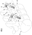
- FIG. 1 A spinal column stabilization system is shown by way of example, denoted overall by the reference numeral 10, which system comprises two bone screws 12 and a connecting element 14 attached to the two bone screws 12.
- the bone screws 12 are each fixed to a vertebra 16 of a vertebral column 18.
- the spinal column stabilization system 10 can of course also comprise more than two bone screws 12. These can be connected to one another via one or more connecting elements 14, for example.
- a connecting element 14 is shown as an example in the form of a round rod.
- Plate-shaped connecting elements with correspondingly designed sections which can be inserted into connecting element receptacles of the bone screws 12 and, for example, each can be fixed with a fixing screw 20, are also conceivable.
- the bone screws 12 can in principle be conventional pedicle screws available on the market. However, at least one of the bone screws 12 is preferably designed in the form of a pedicle screw system 22, which is explained in more detail below.
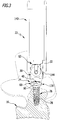
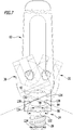
- Each of the pedicle screw systems 22 comprises a pedicle screw 24 with a screw shaft 26, which has an external thread 28, for example in the form of a self-tapping bone thread, and a screw head 30 mounted on the screw shaft 26 in a ball-and-socket joint.
- the screw head 30 has a connecting element receptacle 34 formed between two free legs 32 for the connecting element 14 of the spinal column stabilization system 10.
- An internal thread 36 is also provided on the connecting element receptacle 34, which is designed to correspond to an external thread 38 of the fixing screw 20, so that the fixing screw 20 for fixing the connecting element 14 can be screwed into the connecting element receptacle 34 from free ends of the legs 32, around the connecting element 14 to be fixed on the screw head 30.
- a proximal end of the screw shaft 26 is designed in the form of a joint head 42 with a flat end surface 44 pointing in the proximal direction, which is adjoined by a joint head surface 46 forming part of a spherical surface.
- a tool element receptacle 48 is formed in the joint head 42, for example in the form of a polygonal socket or a polygonal socket.
- a joint head receptacle 50 is formed on the screw head 30 in the form of a seat 52 corresponding to the joint head 42, which opens into an opening 54 which tapers in the inner diameter in the distal direction and which is formed at a distal end 56 of the screw head 30 and from which the screw shaft 26 protrudes distal side of the joint head 42.
- the joint head 42 is adjoined by a thread-free shaft section 58 which is delimited on the distal side by an annular flange 60.
- the annular flange 60 has an outer diameter that is slightly larger than an outer diameter of the joint head 42.
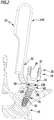
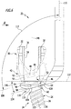
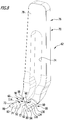
- the pedicle screw system 22 further comprises a bone alignment device 62 and a coupling device 64 for non-positive and / or form-fitting coupling of the bone alignment device 62 and the pedicle screw 24 in an alignment position, as shown, for example, in FIGS Figures 2 to 7 is shown as an example.
- the bone alignment device 62 comprises a clamping plate 66 which forms a coupling section 68 of the bone alignment device 62.
- a handling section 70 adjoins the coupling section 68 on the proximal side.
- the coupling section 68 comprises two clamping legs 72 which run essentially parallel to one another and can be moved resiliently towards one another or away from one another from a basic position and are separated from one another by an insertion slot 74.
- the insertion slot 74 extends partially into the handling section 70.
- a proximal end of the bone alignment device 62 forms a grip area 76 in the form of a connecting plate 78, which connects the two clamping legs 72 to one another.
- a width of the insertion slot 74 increases in the direction of the free ends 80 of the clamping legs 72 so that slide-on surfaces 82 are formed which are inclined towards one another in the distal direction.
- the coupling device 64 comprises first and second coupling elements 84 and 86 which, in the alignment position, are in force-locking and / or form-locking engagement. They are arranged and formed on the one hand on the bone alignment device 62 and on the other hand on the pedicle screw 24.
- the first coupling element 84 is designed in the form of a coupling projection 88
- the second coupling element 86 in the form of a coupling receptacle 90 corresponding to the coupling projection 88 Figures 4 and 5 It is easy to see that the coupling projection 88 engages with the coupling receptacle 90 in the alignment position with a form fit or essentially with a form fit.
- the coupling projection 88 is formed in one piece with the screw shaft 26, specifically in the form of the thread-free shaft section 58. The coupling projection 88 is thus arranged between the external thread 28 and the joint head 42.
- the coupling receptacle 90 is designed in the form of an opening 92, specifically as a bore 94.
- An inner diameter 96 of the bore 94 is adapted to an outer diameter 98 of the thread-free shaft section 58.
- a width 100 of the insertion slot 74 is smaller than the outer diameter 98.
- the coupling receptacle 90 defines a coupling receptacle longitudinal axis 102. This runs perpendicular to a plane 104 which is defined by an underside 106 of the clamping plate 66.
- the coupling section 68 and the handling section 70 each define longitudinal axes 108 and 110, which are angled relative to one another by an angle 112.
- the angle 112 is preferably in a range from approximately 60 ° to approximately 120 ° and can in particular be approximately 90 °.
- the coupling receptacle 90 forms a screw shaft receptacle 114 which the screw shaft 26 penetrates in the alignment position, that is to say at least partially engages in it.
- the coupling device 64 further comprises a stop element 116 on which the bone alignment device 62 is supported on the one hand in the alignment position.
- the underside 106 defines a stop element contact surface 118 which, in the alignment position, lies against the stop element 116.
- the stop element contact surface 118 is flat in the embodiment shown in the figures.
- the stop element 116 has a flat stop surface 120 on which the bone alignment device 62 is supported with its stop element contact surface 118 in the alignment position.
- the stop element 116 is arranged or formed on the screw shaft 26, specifically in the form of the annular flange 60.
- the stop element 116 is preferably formed in one piece with the screw shaft 26.
- the screw shaft 26 can also be connected to the stop element 116 in a non-positive and / or cohesive manner, for example pressed, glued, soldered or welded.
- the annular flange 60 is dimensioned such that its outer diameter 122 is larger than a maximum outer diameter 124 of the external thread 28.
- the stop element 116 directly adjoins the external thread 28.
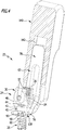
- the screw head 30 has a contact surface 126 pointing in the direction of the external thread 28, on which the bone alignment device 62 is supported in the alignment position, with an upper side 128 of the clamping plate 66 of the same.
- the contact surface 126 is flat in the screw head 30 shown by way of example in the figures. Alternatively, it can also be designed with a concave curve pointing from the screw head 30 in the direction of the external thread 28.
- the upper side 128 of the bone alignment device 62 defines a guide surface 130 for specifying a direction of movement for a relative movement between the screw head 30 and the screw shaft 26.
- a guide surface 130 for specifying a direction of movement for a relative movement between the screw head 30 and the screw shaft 26.
- the guide surface 130 is convexly curved in the direction of the screw head 30 and can in particular form part of a cylinder surface 134, in particular part of a surface of a straight circular cylinder.
- the pivot axis 132 runs transversely, in the embodiment shown in the figures, perpendicular to the coupling receptacle longitudinal axis 102. Thus, as in particular in FIG Figure 6 As shown, the pivot axis 132 also runs perpendicular to a screw shaft longitudinal axis 136 of the screw shaft 26.
- the clamping plate 66 forms a guide body 138 which comprises the guide surface 130, the stop element contact surface 118 and the second coupling element 86.
- the special configuration of the bone alignment device 62 enables, due to the special arrangement and design of the insertion slot 74, that the clamping legs 72 from the in Figure 8 basic position shown are resiliently movable towards or away from one another.
- the clamping legs 72 are spread open slightly so that the insertion slot 74, which is narrower than the outer diameter 98 in the basic position, is widened slightly. If the shaft section 58 slides on the sliding surfaces 82, the insertion slot 74 widens and the shaft section 58 can be inserted through it into the coupling receptacle 90. If the shaft section 58 engages in the coupling receptacle 90, the clamping legs 72 snap or spring back towards one another and partially enclose the shaft section 58. In the manner described, the bone alignment device 62, specifically its coupling section 68, can be clipped or snapped onto the pedicle screw 24.
- the guide surface 130 only allows the screw head 30 to be pivoted exclusively about the pivot axis 132 relative to the screw shaft 26.
- the bone alignment device 62 thus restricts the mobility of the screw head 30 and the screw shaft 26 from originally three degrees of freedom of rotation, which are defined by the ball joint 40, to only a single degree of rotation, which is defined by the pivot axis 132. So it is only the pivoting movement, as in Figure 7 shown schematically, possible about the pivot axis 132.
- the pedicle screw 24 embodied as a polyaxial screw, in cooperation with the bone alignment device 62, is practically reduced to the functionality of a monoaxial screw in which the screw head 30 can only be pivoted about the one pivot axis 132 relative to the screw shaft 26.
- the pedicle screw system 22 optionally includes a blocking sleeve 140. This has a corresponding to the handling section 70 formed receptacle 142, into which the handling section 70 can be inserted parallel to the longitudinal axis 110, as exemplified in FIG Figure 4 is shown.
- the receptacle 142 is closed on all sides up to close to a distal end 144 of the blocking sleeve 140 so that the clamping legs 72 can no longer be pivoted away from one another.
- the bone alignment device 62 coupled to the pedicle screw 24 can then no longer be released from the pedicle screw 24 without the blocking sleeve 140 being pulled off the handling section 70 in the proximal direction.
- the top 128 of the guide body 138 is inclined relative to the bottom 106 in the exemplary embodiment shown in the figures by an alignment angle 146.
- the alignment angle 146 specifies the inclination of a longitudinal axis 148 of the screw head 30 relative to the screw shaft longitudinal axis 136.
- the pedicle screw system 22 can comprise a plurality of bone alignment devices 62 which differ in the design of the guide body 138 in such a way that they have different alignment angles 146.
- the pedicle screw system 22 can comprise a set of bone alignment devices 62, which enable a surgeon to select an alignment of the longitudinal axis 148 and the screw shaft longitudinal axis 136 in a targeted manner and thus to specify a pivoting direction for the screw head 30 for the pedicle screw 24, which temporarily forms a monoaxial screw in the alignment position.
- the described set of bone alignment devices 62 with different alignment angles 146 enables a surgeon to select an intraoperative setting of the pivot axis 132.
- a doctor can influence the position of the screw head 30 after a rotation of the vertebra 16 with the aid of the bone alignment device 62 and consequently the insertion of the connecting element 14 into the connecting element receptacle 34 of the pedicle screw 24 simplify.
- the bone alignment device 62 is detached from the pedicle screw 24 again in the manner described.
Description
- Die vorliegende Erfindung betrifft ein Pedikelschraubensystem umfassend eine Pedikelschraube mit einem Schraubenschaft, welcher ein Außengewinde aufweist, und einem kugelgelenkig am Schraubenschaft gelagerten Schraubenkopf, welcher Schraubenkopf eine Verbindungselementaufnahme für ein Verbindungselement eines Wirbelsäulenstabilisierungssystems umfasst.
- Ferner betrifft die vorliegende Erfindung ein Wirbelsäulenstabilisierungssystem umfassend mindestens zwei Knochenschrauben und mindestens ein an den mindestens zwei Knochenschrauben festlegbares Verbindungselement.
- Pedikelschrauben und Wirbelsäulenstabilisierungssysteme der eingangs beschriebenen Art sind beispielsweise aus der
DE 10 2013 100 574 A1 bekannt. Mit ihnen lassen sich beispielsweise bei Deformitätenoperationen deformierte Wirbelsäulen durch entsprechende Implantation und Ausrichtung von Pedikelschrauben in eine gewünschte Form bringen und in dieser fixieren. Zur Ausrichtung einzelner, fehlgestellter Wirbel werden die Kräfte für die Korrekturmanöver über die Pedikelschrauben in den jeweiligen Wirbel eingeleitet. - Bei Pedikelschraubensystemen, bei denen ein Verbindungselement von oben in eine entsprechende Verbindungselementaufnahme am Schraubenkopf eingesetzt werden kann, also bei sogenannten "Tulpen"-Systemen, ist eine Krafteinleitung nicht möglich, wenn die Pedikelschraube in Form einer Polyaxialschraube ausgebildet ist. Eine Krafteinleitung ist nur möglich, wenn der Schraubenkopf relativ zum Schraubenschaft unbeweglich oder maximal um eine Achse verschwenkbar ist, es sich also bei der Pedikelschraube um eine sogenannte Monoaxialschraube handelt. Der Schraubenkopf wird dabei in einer Ebene bewegt, welche senkrecht zur Achse, um die verschwenkt wird, verläuft, so dass die Monoaxialschraube in diesem Sinne auch als Uniplanarschraube bezeichnet werden kann. Bei Polyaxialschrauben hingegen, die das Einsetzen des Verbindungselements, beispielsweise eines Stabs, deutlich dadurch vereinfachen, dass der Schraubenkopf beliebig relativ zum Schraubenschaft orientiert werden kann, ist eine solche Krafteinleitung und Korrektur einer Ausrichtung eines Wirbels nicht oder nur rudimentär möglich. Insbesondere ist es nicht möglich, die Technik der segmentalen Derotation bei Polyaxialschrauben anzuwenden. Diese ist nur bei direkter Krafteinleitung in die Pedikelschraube, wie es insbesondere die beschriebenen Monoaxialschrauben ermöglichen, realisierbar.
- Aus der
DE 10 2011 053 295 A1 ist eine polyaxiale Pedikelschraube mit provisorischer Fixierung bekannt. In derDE 92 02 587 U1 ist ein Repositions-Instrument beschrieben. Eine Retraktionsvorrichtung zum minimalinvasiven Öffnen eines Zwischenwirbelzugangs ist in derUS 2008/0262318 offenbart. Außerdem ist aus derUS 2015/0238235 A1 ein Instrument zum Verriegeln und Verhindern einer Rotation einer polyaxialen Pedikelschraube bekannt. - Es ist daher eine Aufgabe der vorliegenden Erfindung, ein Pedikelschraubensystem und ein Wirbelsäulenstabilisierungssystem der eingangs beschriebenen Art so weiter zu bilden, dass deren Handhabung verbessert wird.
- Diese Aufgabe wird bei einem Pedikelschraubensystem der eingangs beschriebenen Art erfindungsgemäß dadurch gelöst, dass es eine Knochenausrichtvorrichtung und eine Kopplungseinrichtung umfasst zum kraft- und/oder formschlüssigen Koppeln der Knochenausrichtvorrichtung und der Pedikelschraube in einer Ausrichtstellung, in welcher eine Beweglichkeit des Schraubenkopfs und des Schraubenschafts von drei Bewegungsfreiheitsgraden der Rotation des kugelgelenkig am Schraubenschaft gelagerten Schraubenkopfs um mindestens einen Rotationsfreiheitsgrad reduziert ist, nämlich von ursprünglich drei Bewegungsfreiheitsgraden der Rotation auf einen oder zwei Bewegungsfreiheitsgrade der Rotation, wobei der Schraubenkopf eine in Richtung auf das Außengewinde hin weisende Anlagefläche aufweist, an welcher sich die Knochenausrichtvorrichtung in der Ausrichtstellung abstützt.
- Die erfindungsgemäß vorgeschlagene Weiterbildung ermöglicht es dem Operateur insbesondere, über die Knochenausrichtvorrichtung Kräfte zum Bewegen, insbesondere Rotieren, deformierter Wirbel einer Wirbelsäule direkt auf den Schraubenschaft einzuleiten, wenn die Kopplungseinrichtung des Pedikelschraubensystems die Ausrichtstellung einnimmt. Das vorgeschlagene Pedikelschraubensystem vereinigt somit einerseits die Vorteile von Polyaxialschrauben, die eine beliebige Ausrichtung des Schraubenkopfs relativ zum Schraubenschaft ermöglichen, um das Einsetzen des Verbindungselements in die Verbindungselementaufnahme am Schraubenkopf zu erleichtern, und andererseits, insbesondere bei der Beschränkung der Bewegungsfreiheitsgrade der Rotation auf einen Rotationsfreiheitsgrad, die Vorteile einer Monoaxialschraube, die das Einleiten von Kräften auf den Schraubenschaft zur Ausrichtung eines Wirbelkörpers, in den die Pedikelschraube eingeschraubt ist, ermöglicht. Die Zahl der ursprünglich drei Bewegungsfreiheitsgrade der Rotation kann auf einen oder zwei Bewegungsfreiheitsgrade der Rotation beschränkt sein. Gemäß der Erfindung weist der Schraubenkopf eine in Richtung auf das Außengewinde hin weisende Anlagefläche auf, an welcher sich die Knochenausrichtvorrichtung in der Ausrichtstellung abstützt. Diese Ausgestaltung ermöglicht insbesondere eine direkte Kraftübertragung von der Knochenausrichtvorrichtung auf den Schraubenkopf beziehungsweise eine direkte Einwirkung auf diesen zum Blockieren von mindestens zwei Rotationsfreiheitsgraden des kugelgelenkig mit dem Schraubenschaft zusammenwirkenden Schraubenkopfs.
- Durch die Kopplung der Knochenausrichtvorrichtung und der Pedikelschraube in der Ausrichtstellung wird insbesondere temporär eine Anordnung geschaffen, die in ihrer Funktion einer Monoaxialschraube entspricht. Von den ursprünglich drei Bewegungsfreiheitsgraden, die die kugelgelenkige Verbindung zwischen dem Schraubenschaft und dem Schraubenkopf ermöglicht, wird durch die Kopplung der Pedikelschraube und der Knochenausrichtvorrichtung in der Ausrichtstellung die Zahl der Bewegungsfreiheitsgrade zwischen Schraubenschaft und Schraubenkopf auf einen Bewegungsfreiheitsgrad der Rotation reduziert. Dies entspricht einer Rotation des Schraubenschafts und des Schraubenkopfs relativ zueinander um lediglich eine einzige Schwenkachse. Durch die Kopplungseinrichtung kann insbesondere eine axiale und/oder drehfeste Verbindung zwischen der Knochenausrichtvorrichtung und der Pedikelschraube hergestellt und somit über die Knochenausrichtvorrichtung eine indirekte Kraftübertragung beispielsweise von der Knochenausrichtvorrichtung auf den Schraubenschaft ermöglicht werden.
- Günstig ist es, wenn die Knochenausrichtvorrichtung in Form einer Klemmplatte ausgebildet ist oder eine Klemmplatte umfasst. Beispielsweise kann die Klemmplatte an der Pedikelschraube zwischen dem Schraubenkopf und dem Außengewinde klemmend angeordnet werden, um so eine freie Rotation des Schraubenkopfs relativ zum Schraubenschaft teilweise zu blockieren und nur noch eine Verschwenkbewegung um eine einzige Schwenkachse, wie dies bei einer Monoaxialschraube der Fall ist, zu gestatten.
- Vorteilhaft ist es, wenn die Kopplungseinrichtung erste und zweite Kopplungselemente umfasst, welche in der Ausrichtstellung kraft- und/oder formschlüssig in Eingriff stehen und einerseits an der Knochenausrichtvorrichtung und andererseits an der Pedikelschraube angeordnet oder ausgebildet sind. Mit einer solchen Kopplungseinrichtung kann die Knochenausrichtvorrichtung mit der Pedikelschraube auf einfache und sichere Weise in Eingriff gebracht werden.
- Vorzugsweise sind das erste Kopplungselement in Form eines Kopplungsvorsprungs und das zweite Kopplungselement in Form einer zum Kopplungsvorsprung korrespondierenden Kopplungsaufnahme ausgebildet. Derartige Kopplungselemente lassen sich auf einfache Weise ausbilden und wahlweise an der Pedikelschraube oder an der Knochenausrichtvorrichtung anordnen oder ausbilden.
- Um insbesondere ein unbeabsichtigtes Ablösen der Knochenausrichtvorrichtung von der Pedikelschraube in der Ausrichtstellung zu vermeiden oder ein Risiko hierfür zu minimieren, ist es vorteilhaft, wenn der Kopplungsvorsprung in der Ausrichtstellung formschlüssig oder im Wesentlichen formschlüssig in die Kopplungsaufnahme eingreift.
- Ein besonders stabiles Pedikelschraubensystem lässt sich insbesondere dadurch erhalten, dass der Kopplungsvorsprung einstückig mit dem Schraubenschaft ausgebildet ist.
- Auf besonders einfache Weise herstellen lässt sich das Pedikelschraubensystem, wenn der Kopplungsvorsprung in Form eines gewindefreien Schaftabschnitts des Schraubenschafts ausgebildet ist. Der gewindefreie Schaftabschnitt kann insbesondere einen kreisförmigen Querschnitt aufweisen oder einen unrunden Querschnitt, beispielsweise in Form eines Ovals, eines Vielrunds oder eines Vielecks. So kann beispielsweise bei einem kreisförmigen Querschnitt eine Verdrehung zwischen der Knochenausrichtvorrichtung und der Pedikelschraube ermöglicht werden oder aber auch eine drehfeste Verbindung mit einem unrunden Querschnitt hergestellt werden.
- Gemäß einer weiteren bevorzugten Ausführungsform der Erfindung kann vorgesehen sein, dass der Schraubenschaft einen Gelenkkopf aufweist und dass der Schraubenkopf eine zum Gelenkkopf korrespondierende Gelenkkopfaufnahme zur Ausbildung eines Kugelgelenks im Zusammenwirken mit dem Gelenkkopf aufweist. Durch den Gelenkkopf im Zusammenwirken mit der Gelenkkopfaufnahme kann so auf einfache Weise ein Kugelgelenk gebildet werden. Der Gelenkkopf kann insbesondere die Form einer Kugel oder eines Teils einer Kugel aufweisen. Die Gelenkkopfaufnahme kann insbesondere in Form eines zu einer Gelenkkugel korrespondierenden hohlkugeligen Sitzes geformt sein.
- Auf einfache Weise lassen sich Rotationsfreiheitsgrade zwischen dem Schraubenkopf und dem Schraubenschaft ausschalten, wenn der Kopplungsvorsprung zwischen dem Außengewinde und dem Gelenkkopf angeordnet ist. Beispielsweise kann so mit der Knochenausrichtvorrichtung eine Bewegung des Schraubenkopfs relativ zum Schraubenschaft auf einfache Weise blockiert werden, beispielsweise durch eine klemmende Verbindung.
- Vorteilhaft ist es, wenn die Kopplungseinrichtung ein Anschlagelement umfasst, an welchem sich die Knochenausrichtvorrichtung in der Ausrichtstellung abstützt. Beispielsweise kann das Anschlagelement am Schraubenschaft ausgebildet sein, sodass sich die Knochenausrichtvorrichtung einerseits am Anschlagelement und andererseits am Schraubenkopf abstützen kann.
- Günstigerweise weist die Knochenausrichtvorrichtung eine Anschlagelementanlagefläche auf, welche in der Ausrichtstellung am Anschlagelement anliegt. Dies ermöglicht es insbesondere, dass sich die Knochenausrichtvorrichtung in der Ausrichtstellung direkt am Anschlagelement abstützt. Wenn sich die Knochenausrichtvorrichtung andererseits am Schraubenkopf abstützen kann, kann eine Beweglichkeit des Schraubenkopfs relativ zum Schraubenschaft auf einfache Weise eingeschränkt werden.
- Vorzugsweise ist die Anschlagelementanlagefläche eben oder im Wesentlichen eben ausgebildet. Diese Ausgestaltung ermöglicht insbesondere eine flächige Anlage am Anschlagelement, wenn dieses eine ebene oder im Wesentlichen ebene Anschlagfläche aufweist, an welcher die Anschlagelementanlagefläche in der Ausrichtstellung anliegt.
- Günstig ist es, wenn das Anschlagelement eine ebene oder im Wesentlichen ebene Anschlagfläche aufweist, an welcher sich die Knochenausrichtvorrichtung in der Ausrichtstellung abstützt. Eine solche Anschlagfläche ist auf einfache Weise auszubilden und ermöglicht eine flächige Anlage der Knochenausrichtvorrichtung am Anschlagelement, wenn die Anschlagelementanlagefläche eben oder im Wesentlichen eben ausgebildet ist.
- Ein besonders kompakter Aufbau des Pedikelschraubensystems lässt sich insbesondere dadurch erreichen, dass das Anschlagelement am Schraubenschaft angeordnet oder ausgebildet ist.
- Besonders einfach herstellen lässt sich der Schraubenschaft, wenn das Anschlagelement in Form eines Ringflansches ausgebildet ist. Beispielsweise kann der Schraubenschaft so durch Gießen oder spanende Bearbeitung hergestellt werden.
- Gemäß einer weiteren bevorzugten Ausführungsform der Erfindung kann vorgesehen sein, dass das Anschlagelement einstückig mit dem Schraubenschaft ausgebildet oder kraft- und/oder stoffschlüssig mit dem Schraubenschaft verbunden ist. Insbesondere kann das Anschlagelement mit dem Schraubenschaft verpresst, verklebt, verlötet oder verschweißt sein. Je nach Art und Ausbildung des Schraubenschafts und des Schraubenkopfs sowie der Art der kugelgelenkigen Verbindung derselben kann es wahlweise vorteilhaft sein, das Anschlagelement einstückig mit dem Schraubenschaft auszubilden oder kraft- und/oder stoffschlüssig mit diesem zu verbinden.
- Vorteilhaft ist es, wenn ein Außendurchmesser des Anschlagelements größer ist als ein maximaler Außendurchmesser des Außengewindes. So kann sichergestellt werden, dass in der Ausrichtstellung die Knochenausrichtvorrichtung nicht mit dem Außengewinde in Kontakt treten kann.
- Insbesondere bei kurzen Schraubenschäften ist es vorteilhaft, wenn das Anschlagelement direkt an das Außengewinde angrenzt. So kann der Schraubenschaft bis zum Anschlagelement in einen Knochen eingeschraubt werden.
- Auf besonders einfache Weise herstellen lässt sich der Schraubenkopf, wenn die Anlagefläche eben oder im Wesentlichen eben oder vom Schraubenkopf weg weisend konkav gekrümmt ausgebildet ist. Vorzugsweise wird die Anlagefläche derart geformt, dass eine flächige Anlage an der Knochenausrichtvorrichtung möglich ist.
- Gemäß einer weiteren bevorzugten Ausführungsform der Erfindung kann vorgesehen sein, dass die Knochenausrichtvorrichtung eine Führungsfläche zum Vorgeben einer Bewegungsrichtung für eine Relativbewegung zwischen dem Schraubenkopf und dem Schraubenschaft aufweist und dass der Schraubenkopf in der Ausrichtstellung an der Führungsfläche anliegt und an dieser um eine Schwenkachse relativ zum Schraubenschaft verschwenkbar geführt ist. Mit der Führungsfläche ist es so insbesondere auf einfache Weise möglich, die gewünschte Relativbewegung zwischen dem Schraubenkopf und dem Schraubenschaft vorzugeben, also insbesondere nur eine Verschwenkbewegung um eine einzige Schwenkachse zuzulassen. Dies kann auf einfache Weise durch Formgebung der Führungsfläche erreicht werden. Insbesondere kann die Führungsfläche in Richtung auf den Schraubenkopf hin weisend konvex gekrümmt sein. Beispielsweise kann sie sich koaxial zur Schwenkachse erstrecken oder kann die Schwenkachse auf der Führungsfläche liegen.
- Vorzugsweise bildet die Führungsfläche einen Teil einer Zylinderoberfläche. Günstigerweise bildet sie einen Teil einer Oberfläche eines geraden Kreiszylinders. Insbesondere kann eine vom geraden Kreiszylinder definierte Längsachse die Schwenkachse definieren oder kann die Schwenkachse auf der Oberfläche liegen und parallel zur Längsachse des geraden Kreiszylinders verlaufen.
- Vorteilhafterweise verläuft die Schwenkachse in der Ausrichtstellung quer zu einer Schraubenschaftlängsachse des Schraubenschafts. Insbesondere kann die Schwenkachse senkrecht zur Schraubenschaftlängsachse verlaufen. Selbstverständlich kann die Schwenkachse auch bezogen auf eine senkrecht zur Schraubenschaftlängsachse verlaufende Ebene geneigt verlaufen und mit dieser einen Neigungswinkel einschließen, beispielsweise in einem Bereich von etwa 0° bis etwa 30°. Dies ermöglicht es insbesondere, den Schraubenkopf und den Schraubenschaft in der Ausrichtstellung relativ zueinander um den Neigungswinkel geneigt zu halten, jedoch noch eine Verschwenkbewegung um die Schwenkachse zu ermöglichen.
- Vorteilhaft ist es, wenn die Knochenausrichtvorrichtung einen Führungskörper umfasst und wenn der Führungskörper die Führungsfläche, die Anschlagelementanlagefläche und/oder eines der Kopplungselemente der Kopplungseinrichtung umfasst. Ein derart ausgebildeter Führungskörper kann somit mehrere Funktionen ausüben und ermöglicht insgesamt einen möglichst kompakten Aufbau der Knochenausrichtvorrichtung und des Pedikelschraubensystems.
- Vorzugsweise ist die Kopplungsaufnahme in Form einer Ausnehmung oder Durchbrechung der Knochenausrichtvorrichtung ausgebildet. Diese lassen sich einfach herstellen.
- Günstigerweise ist die Kopplungsaufnahme in Form einer Bohrung ausgebildet. Eine solche ist auf einfache Weise herzustellen. Insbesondere kann eine Längsachse der Bohrung auch eine Ausrichtung des Schraubenkopfs relativ zum Schraubenschaft vorgeben.
- Um die Handhabung des Pedikelschraubensystems für einen Operateur weiter zu verbessern, ist es günstig, wenn die Knochenausrichtvorrichtung einen Kopplungsabschnitt und einen Handhabungsabschnitt umfasst und wenn der Kopplungsabschnitt eines der Kopplungselemente der Kopplungseinrichtung umfasst. Mit einer solchen Knochenausrichtvorrichtung ist es möglich, eine Verbindung in der Ausrichtstellung zwischen dem Kopplungsabschnitt und der Pedikelschraube herzustellen. Ein Operateur kann dann den Handhabungsabschnitt entweder mit einer Hand oder einem weiteren Instrument fassen und auf diese Weise eine Kraft auf die Pedikelschraube ausüben zum Ausrichten des Schraubenschafts und damit des mit diesem verbundenen Wirbels in einer gewünschten Weise.
- Auf besonders einfache Weise lässt sich die Knochenausrichtvorrichtung mit der Pedikelschraube koppeln, wenn die Knochenausrichtvorrichtung auf die Pedikelschraube aufclipsbar oder aufrastbar ausgebildet ist. Vorzugsweise ist der Kopplungsabschnitt der Knochenausrichtvorrichtung auf die Pedikelschraube aufclipsbar oder aufrastbar ausgebildet.
- Eine einfache Kopplung zwischen der Knochenausrichtvorrichtung und der Pedikelschraube kann insbesondere dadurch realisiert werden, dass der Kopplungsabschnitt zwei im Wesentlichen parallel zueinander verlaufende, aus einer Grundstellung federnd aufeinander zu oder voneinander weg bewegbare Klemmschenkel aufweist und dass die Klemmschenkel durch einen Einführschlitz zum Einführen des an der Pedikelschraube ausgebildeten Kopplungselements voneinander getrennt sind. Beispielsweise kann das an der Pedikelschraube ausgebildete Kopplungselement in Form eines gewindefreien Schaftabschnitts in den Einführschlitz eingeführt werden, sodass dieser etwas ausgeweitet wird, bis das Kopplungselement der Pedikelschraube in die Kopplungselementaufnahme der Knochenausrichtvorrichtung in der Ausrichtstellung eingreift, beispielsweise einschnappt. Die Klemmschenkel können dann in der Ausrichtstellung wieder in ihre Grundstellung zurückfedern oder in der Ausrichtstellung noch etwas unter Vorspannung gehalten sein, sodass eine zusätzliche Klemmwirkung der Klemmschenkel erreicht wird, um die Knochenausrichtvorrichtung klemmend an der Pedikelschraube zu halten.
- Um das Einführen des an der Pedikelschraube ausgebildeten Kopplungselements in die Kopplungsaufnahme der Knochenausrichtvorrichtung zu erleichtern, ist es vorteilhaft, wenn eine Breite des Einführschlitzes in Richtung auf ein freies Ende der Klemmschenkel hin zunimmt. Beispielsweise können freie Enden der Klemmschenkel Aufgleitflächen aufweisen, die das Einführen des an der Pedikelschraube ausgebildeten Kopplungselements in den Einführschlitz zu erleichtern.
- Damit das in Eingriff Bringen der Knochenausrichtvorrichtung mit der Pedikelschraube weiter erleichtert wird, ist es günstig, wenn sich der Einführschlitz teilweise in den Handhabungsabschnitt hinein erstreckt. Dies ermöglicht insbesondere die Ausbildung sehr langer Klemmschenkel, die dann zum Koppeln der Knochenausrichtvorrichtung und der Pedikelschraube miteinander in der Ausrichtstellung nur wenig aufgespreizt werden müssen.
- Um die Knochenausrichtvorrichtung im Wesentlichen ohne die Ausübung von Klemmkräften mit der Pedikelschraube zu koppeln, ist es vorteilhaft, wenn ein Innendurchmesser der Kopplungsaufnahme an einen Außendurchmesser des gewindefreien Schaftabschnitts angepasst ist.
- Ferner kann vorgesehen sein, dass die Kopplungsaufnahme eine Kopplungsaufnahmelängsachse definiert und dass die Kopplungsaufnahmelängsachse quer zur Schwenkachse verläuft. Beispielsweise kann sie senkrecht zur Schwenkachse verlaufen. Insbesondere kann die Kopplungsaufnahme derart ausgebildet sein, dass die Kopplungsaufnahmelängsachse in der Ausrichtstellung mit einer vom Schraubenkopf definierten Längsachse zusammenfällt und relativ zur Schraubenschaftlängsachse um den oben beschriebenen Neigungswinkel geneigt ist.
- Um insbesondere einen Einsatz des Pedikelschraubensystems bei minimalinvasiven chirurgischen Eingriffen zu ermöglichen, ist es vorteilhaft, wenn der Kopplungsabschnitt und der Handhabungsabschnitt gegeneinander abgewinkelt sind. Vorzugsweise liegt ein Winkel der Abwinklung in einem Bereich von etwa 70° bis etwa 110°.
- Damit die Knochenausrichtvorrichtung einfach und sicher gefasst und gehalten werden kann, ist es vorteilhaft, wenn der Handhabungsabschnitt einen die beiden Klemmschenkel miteinander verbindenden Griffbereich umfasst. So kann ein Operateur die Knochenausrichtvorrichtung mit der daran gekoppelten Pedikelschraube einfach und sicher manipulieren.
- Ferner ist es günstig, wenn das Pedikelschraubensystem mehrere Knochenausrichtvorrichtungen umfasst, bei denen die Anschlagelementanlagefläche und eine Führungsflächenlängsachse der Führungsfläche unterschiedliche Ausrichtwinkel relativ zueinander aufweisen. Mit einem solchen Satz von Knochenausrichtvorrichtungen des Pedikelschraubensystems kann ein Operateur jeweils diejenige Knochenausrichtvorrichtung auswählen, mit der er einen festen Neigungswinkel des Schraubenschafts und des Schraubenkopfs relativ zueinander in der Ausrichtstellung vorgeben möchte. Beispielsweise kann der Satz um jeweils 10° abgestufte Neigungswinkel aufweisen, um den Neigungswinkel des Schraubenschafts und des Schraubenkopfs relativ zueinander in der Ausrichtstellung in definierten Stufen vorgeben zu können, beispielsweise mit Neigungswinkeln von 0°, 10°, 20° und so weiter.
- Vorteilhaft ist es, wenn die Knochenausrichtvorrichtung eine Schraubenschaftaufnahme aufweist, in die der Schraubenschaft in der Ausrichtstellung mindestens teilweise eingreift. Insbesondere kann der Schraubenschaft die Schraubenschaftaufnahme in der Ausrichtstellung durchsetzen, also beispielsweise mit einem distalen Ende des Schraubenschafts aus der Schraubenschaftaufnahme distalseitig vorstehen.
- Besonders einfach und kompakt ausbilden lässt sich das Pedikelschraubensystem, wenn die Kopplungsaufnahme die Schraubenschaftaufnahme definiert.
- Die eingangs gestellte Aufgabe wird ferner bei einem Wirbelsäulenstabilisierungssystem der eingangs beschriebenen Art erfindungsgemäß dadurch gelöst, dass mindestens eine der mindestens zwei Knochenschrauben in Form eines der oben beschriebenen Pedikelschraubensysteme ausgebildet ist.
- Ein derart weitergebildetes Wirbelsäulenstabilisierungssystem weist dann insbesondere auch die oben im Zusammenhang mit bevorzugten Ausführungsformen von Pedikelschraubensystemen beschriebenen Vorteile auf.
- Die nachfolgende Beschreibung einer bevorzugten Ausführungsform der Erfindung dient im Zusammenhang mit der Zeichnung der näheren Erläuterung. Es zeigen:
- Figur 1:
- eine schematische Ansicht eines Wirbelsäulenstabilisierungssystems umfassend zwei Knochenschrauben und ein Verbindungselement, welches an einer Wirbelsäule festgelegt ist;
- Figur 2:
- eine Seitenansicht einer in einen Wirbel eingeschraubten Pedikelschraube mit daran gekoppelter Knochenausrichtvorrichtung;
- Figur 3:
- eine weitere Seitenansicht des in
Figur 2 dargestellten Pedikelschraubensystems; - Figur 4:
- eine perspektivische Ansicht des Pedikelschraubensystems aus
Figur 2 ; - Figur 5:
- eine Ansicht der Anordnung aus
Figur 4 von vorn; - Figur 6:
- eine Seitenansicht einer mit einer Pedikelschraube gekoppelten Knochenausrichtvorrichtung;
- Figur 7:
- eine Ansicht in Richtung des Pfeils A in
Figur 6 ; und - Figur 8:
- eine perspektivische Ansicht der Knochenausrichtvorrichtung aus
Figur 6 . - In
Figur 1 ist beispielhaft ein insgesamt mit dem Bezugszeichen 10 bezeichnetes Wirbelsäulenstabilisierungssystem dargestellt, welches zwei Knochenschrauben 12 und ein an den beiden Knochenschrauben 12 festgelegtes Verbindungselement 14 umfasst. Die Knochenschrauben 12 sind an jeweils einem Wirbel 16 einer Wirbelsäule 18 festgelegt. - Selbstverständlich kann das Wirbelsäulenstabilisierungssystem 10 auch mehr als zwei Knochenschrauben 12 umfassen. Diese können beispielsweise über ein oder mehrere Verbindungselemente 14 miteinander verbunden werden.
- In
Figur 1 ist ein Verbindungselement 14 beispielhaft in Form eines Rundstabes dargestellt. Denkbar sind auch plattenförmige Verbindungselemente mit entsprechend ausgebildeten Abschnitten, die in Verbindungselementaufnahmen der Knochenschrauben 12 eingesetzt und beispielsweise mit jeweils einer Fixierschraube 20 festgelegt werden können. - Bei den Knochenschrauben 12 kann es sich grundsätzlich um herkömmliche, am Markt verfügbare Pedikelschrauben handeln. Vorzugsweise ist mindestens eine der Knochenschrauben 12 jedoch in Form eines Pedikelschraubensystems 22 ausgebildet, welches nachfolgend im Einzelnen näher erläutert wird.
- Jedes der Pedikelschraubensysteme 22 umfasst eine Pedikelschraube 24 mit einem Schraubenschaft 26, welcher ein Außengewinde 28 aufweist, beispielsweise in Form eines selbstschneidenden Knochengewindes, und einen kugelgelenkig am Schraubenschaft 26 gelagerten Schraubenkopf 30. Der Schraubenkopf 30 weist eine zwischen zwei freien Schenkeln 32 gebildete Verbindungselementaufnahme 34 für das Verbindungselement 14 des Wirbelsäulenstabilisierungssystems 10 auf.
- An der Verbindungselementaufnahme 34 ist ferner ein Innengewinde 36 vorgesehen, welches korrespondierend zu einem Außengewinde 38 der Fixierschraube 20 ausgebildet ist, sodass die Fixierschraube 20 zum Festlegen des Verbindungselements 14 ausgehend von freien Enden der Schenkel 32 in die Verbindungselementaufnahme 34 eingeschraubt werden kann, um das Verbindungselement 14 am Schraubenkopf 30 festzulegen.
- Zur Ausbildung eines Kugelgelenks 40 zwischen dem Schraubenschaft 26 und dem Schraubenkopf 30 ist ein proximales Ende des Schraubenschafts 26 in Form eines Gelenkkopfs 42 ausgebildet mit einer in proximaler Richtung weisenden ebenen Endfläche 44, an welche eine einen Teil einer Kugeloberfläche bildende Gelenkkopffläche 46 angrenzt. In proximaler Richtung weisend ist im Gelenkkopf 42 eine Werkzeugelementaufnahme 48 ausgebildet, beispielsweise in Form eines Innenvielkant oder eines Innenvielrund.
- Am Schraubenkopf 30 ist eine Gelenkkopfaufnahme 50 ausgebildet in Form eines korrespondierend zum Gelenkkopf 42 ausgebildeten Sitzes 52, welcher in eine in distaler Richtung sich im Innendurchmesser verjüngende Durchbrechung 54 mündet, die an einem distalen Ende 56 des Schraubenkopfs 30 ausgebildet ist und aus der der Schraubenschaft 26 distalseitig des Gelenkkopfs 42 vorsteht.
- Distalseitig schließt sich an den Gelenkkopf 42 ein gewindefreier Schaftabschnitt 58 an, welcher distalseitig von einem Ringflansch 60 begrenzt ist. Der Ringflansch 60 weist einen Außendurchmesser auf, der etwas größer ist als ein Außendurchmesser des Gelenkkopfs 42.
- Das Pedikelschraubensystem 22 umfasst ferner eine Knochenausrichtvorrichtung 62 und eine Kopplungseinrichtung 64 zum kraft- und/oder formschlüssigen Koppeln der Knochenausrichtvorrichtung 62 und der Pedikelschraube 24 in einer Ausrichtstellung, wie sie beispielsweise in den
Figuren 2 bis 7 beispielshaft dargestellt ist. - Die Knochenausrichtvorrichtung 62 umfasst eine Klemmplatte 66, welche einen Kopplungsabschnitt 68 der Knochenausrichtvorrichtung 62 bildet. Proximalseitig schließt sich an den Kopplungsabschnitt 68 ein Handhabungsabschnitt 70 an.
- Der Kopplungsabschnitt 68 umfasst zwei im Wesentlichen parallel zueinander verlaufende, aus einer Grundstellung federnd aufeinander zu oder voneinander weg bewegbare Klemmschenkel 72, die durch einen Einführschlitz 74 voneinander getrennt sind. Der Einführschlitz 74 erstreckt sich teilweise in den Handhabungsabschnitt 70 hinein.
- Ein proximales Ende der Knochenausrichtvorrichtung 62 bildet einen die beiden Klemmschenkel 72 miteinander verbindender Griffbereich 76 in Form einer Verbindungsplatte 78.
- Eine Breite des Einführschlitzes 74 nimmt in Richtung auf freie Enden 80 der Klemmschenkel 72 hin zu, sodass Aufgleitflächen 82 ausgebildet werden, die in distaler Richtung weisend gegeneinander geneigt sind.
- Die Kopplungsreinrichtung 64 umfasst erste und zweite Kopplungselemente 84 und 86, die in der Ausrichtstellung kraft- und/oder formschlüssig in Eingriff stehen. Sie sind einerseits an der Knochenausrichtvorrichtung 62 und andererseits an der Pedikelschraube 24 angeordnet und ausgebildet.
- Bei dem in Figuren schematisch dargestellten Ausführungsbeispiel ist das erste Kopplungselement 84 in Form eines Kopplungsvorsprungs 88 ausgebildet, das zweite Kopplungselement 86 in Form einer zum Kopplungsvorsprung 88 korrespondierenden Kopplungsaufnahme 90. Wie insbesondere in
Figuren 4 und5 gut zu erkennen, greift der Kopplungsvorsprung 88 in der Ausrichtstellung formschlüssig oder im Wesentlichen formschlüssig in die Kopplungsaufnahme 90 ein. - Der Kopplungsvorsprung 88 ist einstückig mit dem Schraubenschaft 26 ausgebildet, und zwar in Form des gewindefreien Schaftabschnitts 58. Somit ist der Kopplungsvorsprung 88 zwischen dem Außengewinde 28 und dem Gelenkkopf 42 angeordnet.
- Die Kopplungsaufnahme 90 ist in Form einer Durchbrechung 92 ausgebildet, und zwar als Bohrung 94. Ein Innendurchmesser 96 der Bohrung 94 ist an einen Außendurchmesser 98 des gewindefreien Schaftabschnitts 58 angepasst. Eine Breite 100 des Einführschlitzes 74 ist kleiner als der Außendurchmesser 98.
- Die Kopplungsaufnahme 90 definiert eine Kopplungsaufnahmelängsachse 102. Diese verläuft senkrecht zu einer Ebene 104, die durch eine Unterseite 106 der Klemmplatte 66 definiert wird.
- Der Kopplungsabschnitt 68 und der Handhabungsabschnitt 70 definieren jeweils Längsachsen 108 und 110, die gegeneinander um einen Winkel 112 abgewinkelt sind. Der Winkel 112 liegt vorzugsweise in einem Bereich von etwa 60° bis etwa 120° und kann insbesondere etwa 90° betragen.
- Bei dem in den Figuren dargestellten Ausführungsbeispiel der Knochenausrichtvorrichtung 62 bildet die Kopplungsaufnahme 90 eine Schraubenschaftaufnahme 114, die der Schraubenschaft 26 in der Ausrichtstellung durchsetzt, also mindestens teilweise in diese eingreift.
- Die Kopplungseinrichtung 64 umfasst ferner ein Anschlagelement 116, an welchem sich die Knochenausrichtvorrichtung 62 in der Ausrichtstellung einerseits abstützt. Die Unterseite 106 definiert eine Anschlagelementanlagefläche 118, die in der Ausrichtstellung am Anschlagelement 116 anliegt. Die Anschlagelementanlagefläche 118 ist bei dem in den Figuren dargestellten Ausführungsbeispiel eben ausgebildet.
- Das Anschlagelement 116 weist eine ebene Anschlagfläche 120 auf, an welcher sich die Knochenausrichtvorrichtung 62 mit ihrer Anschlagelementanlagefläche 118 in der Ausrichtstellung abstützt.
- Das Anschlagelement 116 ist am Schraubenschaft 26 angeordnet beziehungsweise ausgebildet, und zwar in Form des Ringflansches 60. Das Anschlagelement 116 ist vorzugsweise einstückig mit dem Schraubenschaft 26 ausgebildet. Bei alternativen Ausführungsformen kann der Schraubenschaft 26 mit dem Anschlagelement 116 jedoch auch kraft- und/oder stoffschlüssig verbunden sein, beispielsweise verpresst, verklebt, verlötet oder verschweißt.
- Der Ringflansch 60 ist so bemessen, dass dessen Außendurchmesser 122 größer ist als ein maximaler Außendurchmesser 124 des Außengewindes 28. Zudem grenzt das Anschlagelement 116 direkt an das Außengewinde 28 an.
- Ferner weist der Schraubenkopf 30 eine in Richtung auf das Außengewinde 28 hin weisende Anlagefläche 126 auf, an welcher sich die Knochenausrichtvorrichtung 62 in der Ausrichtstellung abstützt, und zwar mit einer Oberseite 128 der Klemmplatte 66 derselben. Die Anlagefläche 126 ist bei dem in den Figuren beispielhaft dargestellten Schraubenkopf 30 eben ausgebildet. Alternativ kann sie auch vom Schraubenkopf 30 in Richtung auf das Außengewinde 28 hin weisend konkav gekrümmt ausgebildet sein.
- Die Oberseite 128 der Knochenausrichtvorrichtung 62 definiert eine Führungsfläche 130 zum Vorgeben einer Bewegungsrichtung für eine Relativbewegung zwischen dem Schraubenkopf 30 und dem Schraubenschaft 26. Wie beispielsweise in
Figur 7 gut zu erkennen, liegt der Schraubenkopf 30 in der Ausrichtstellung an der Führungsfläche 130 an und ist an dieser um eine Schwenkachse 132 relativ zum Schraubenschaft 26 verschwenkbar geführt. - Die Führungsfläche 130 ist in Richtung auf den Schraubenkopf 30 hin konvex gekrümmt ausgebildet und kann insbesondere einen Teil einer Zylinderoberfläche 134 bilden, insbesondere einen Teil einer Oberfläche eines geraden Kreiszylinders.
- Die Schwenkachse 132 verläuft quer, bei dem in den Figuren dargestellten Ausführungsbeispiel senkrecht, zur Kopplungsaufnahmelängsachse 102. Damit, wie insbesondere in
Figur 6 dargestellt, verläuft die Schwenkachse 132 auch senkrecht zu einer Schraubenschaftlängsachse 136 des Schraubenschafts 26. - Die Klemmplatte 66 bildet einen Führungskörper 138, welcher die Führungsfläche 130, die Anschlagelementanlagefläche 118 und das zweite Kopplungselement 86 umfasst.
- Die besondere Ausgestaltung der Knochenausrichtvorrichtung 62 ermöglicht es aufgrund der besonderen Anordnung und Ausbildung des Einführschlitzes 74, dass die Klemmschenkel 72 aus der in
Figur 8 dargestellten Grundstellung aufeinander zu oder voneinander weg federnd bewegbar sind. - Zum Einführen des Kopplungsvorsprungs 88 in die Kopplungsaufnahme 90 durch den Einführschlitz 74 werden die Klemmschenkel 72 etwas aufgespreizt, sodass der Einführschlitz 74, welcher in der Grundstellung schmaler als der Außendurchmesser 98 ist, etwas aufgeweitet wird. Gleitet der Schaftabschnitt 58 an den Aufgleitflächen 82 auf, so weitet sich der Einführschlitz 74 und der Schaftabschnitt 58 kann durch diesen hindurch in die Kopplungsaufnahme 90 eingeschoben werden. Greift der Schaftabschnitt 58 in die Kopplungsaufnahme 90 ein, schnappen beziehungsweise federn die Klemmschenkel 72 aufeinander zu zurück und umschließen den Schaftabschnitt 58 teilweise. In der beschriebenen Weise lässt sich die Knochenausrichtvorrichtung 62, und zwar deren Kopplungsabschnitt 68, auf die Pedikelschraube 24 aufclipsen beziehungsweise aufrasten.
- Die Führungsfläche 130 gestattet es aufgrund ihrer Ausgestaltung nur, den Schraubenkopf 30 ausschließlich um die Schwenkachse 132 relativ zum Schraubenschaft 26 zu verschwenken. Damit schränkt die Knochenausrichtvorrichtung 62 in der Ausrichtstellung die Beweglichkeit des Schraubenkopfs 30 und des Schraubenschafts 26 von ursprünglich drei Bewegungsfreiheitsgraden der Rotation, die durch das Kugelgelenk 40 definiert werden, auf lediglich einen einzigen Rotationsfreiheitsgrad ein, welcher durch die Schwenkachse 132 definiert wird. Es ist also nur noch die Verschwenkbewegung, wie in
Figur 7 schematisch dargestellt, um die Schwenkachse 132 möglich. Damit wird die als Polyaxialschraube ausgebildete Pedikelschraube 24 im Zusammenwirken mit der Knochenausrichtvorrichtung 62 praktisch auf Funktionalität einer Monoaxialschraube reduziert, bei welcher der Schraubenkopf 30 relativ zum Schraubenschaft 26 nur um die eine Schwenkachse 132 verschwenkbar ist. - Um zu verhindern, dass sich die Knochenausrichtvorrichtung 62 unbeabsichtigt von der Pedikelschraube 24 löst, umfasst das Pedikelschraubensystem 22 optional eine Blockierhülse 140. Diese weist eine korrespondierend zum Handhabungsabschnitt 70 ausgebildete Aufnahme 142 auf, in die der Handhabungsabschnitt 70 parallel zur Längsachse 110 eingeschoben werden kann, wie dies beispielhaft in
Figur 4 dargestellt ist. - Die Aufnahme 142 ist bis nahe an ein distales Ende 144 der Blockierhülse 140 heran allseitig geschlossen, sodass die Klemmschenkel 72 nicht mehr voneinander weg verschwenkt werden können. Die an der Pedikelschraube 24 gekoppelte Knochenausrichtvorrichtung 62 lässt sich dann nicht mehr von der Pedikelschraube 24 lösen, ohne dass die Blockierhülse 140 wieder in proximaler Richtung vom Handhabungsabschnitt 70 abgezogen wird.
- Die Oberseite 128 des Führungskörpers 138 ist relativ zur Unterseite 106 bei dem in den Figuren dargestellten Ausführungsbeispiel um einen Ausrichtwinkel 146 geneigt. Der Ausrichtwinkel 146 gibt die Neigung einer Längsachse 148 des Schraubenkopfs 30 relativ zur Schraubenschaftlängsachse 136 vor. Optional kann das Pedikelschraubensystem 22 mehrere Knochenausrichtvorrichtungen 62 umfassen, die sich in der Ausgestaltung des Führungskörpers 138 derart unterscheiden, dass sie unterschiedliche Ausrichtwinkel 146 aufweisen. So kann das Pedikelschraubensystem 22 einen Satz von Knochenausrichtvorrichtungen 62 umfassen, die es einem Operateur ermöglichen, eine Ausrichtung der Längsachse 148 und der Schraubenschaftlängsachse 136 gezielt zu wählen und damit der temporär in der Ausrichtstellung eine Monoaxialschraube bildenden Pedikelschraube 24 eine Schwenkrichtung für den Schraubenkopf 30 vorzugeben.
- Durch den beschriebenen Satz von Knochenausrichtvorrichtungen 62 mit unterschiedlichen Ausrichtwinkeln 146 wird es einem Operateur ermöglicht, eine intraoperative Einstellung der Schwenkachse 132 zu wählen. So kann ein Arzt durch entsprechende Wahl der Knochenausrichtvorrichtung 62 mit dem von ihm gewünschten Ausrichtwinkel 146 die Stellung des Schraubenkopfs 30 nach einer Rotation des Wirbels 16 mit Hilfe der Knochenausrichtvorrichtung 62 beeinflussen und in der Folge das Einsetzen des Verbindungselements 14 in die Verbindungselementaufnahme 34 der Pedikelschraube 24 vereinfachen.
- Mit dem Pedikelschraubensystem 22 ist die teilweise, insbesondere richtungsabhängige, Blockierung der Polyaxialität der Pedikelschraube 24 durch die temporäre Kopplung mit der Knochenausrichtvorrichtung 62 in der Ausrichtstellung sowie optional das intraoperative Einstellen eines Winkels zwischen der Längsachse 148 und der Schraubenschaftlängsachse 136 durch entsprechende Wahl einer Knochenausrichtvorrichtung 62 mit gewünschtem Ausrichtwinkel 146 möglich. Trotzdem bleibt die Möglichkeit, den Schraubenkopf 30 relativ zum Schraubenschaft 26 um die Längsachse 148 zu rotieren, auch in der Ausrichtstellung erhalten.
- Wird wieder die volle Polyaxialität der Pedikelschraube 24 gewünscht, wird in der beschriebenen Weise die Knochenausrichtvorrichtung 62 wieder von der Pedikelschraube 24 gelöst.
-
- 10
- Wirbelsäulenstabilisierungssystem
- 12
- Knochenschraube
- 14
- Verbindungselement
- 16
- Wirbel
- 18
- Wirbelsäule
- 20
- Fixierschraube
- 22
- Pedikelschraubensystem
- 24
- Pedikelschraube
- 26
- Schraubenschaft
- 28
- Außengewinde
- 30
- Schraubenkopf
- 32
- Schenkel
- 34
- Verbindungselementaufnahme
- 36
- Innengewinde
- 38
- Außengewinde
- 40
- Kugelgelenk
- 42
- Gelenkkopf
- 44
- Endfläche
- 46
- Gelenkkopffläche
- 48
- Werkzeugelementaufnahme
- 50
- Gelenkkopfaufnahme
- 52
- Sitz
- 54
- Durchbrechung
- 56
- Ende
- 58
- Schaftabschnitt
- 60
- Ringflansch
- 62
- Knochenausrichtvorrichtung
- 64
- Kopplungseinrichtung
- 66
- Klemmplatte
- 68
- Kopplungsabschnitt
- 70
- Handhabungsabschnitt
- 72
- Klemmschenkel
- 74
- Einführschlitz
- 76
- Griffbereich
- 78
- Verbindungsplatte
- 80
- Ende
- 82
- Aufgleitfläche
- 84
- erstes Kopplungselement
- 86
- zweites Kopplungselement
- 88
- Kopplungsvorsprung
- 90
- Kopplungsaufnahme
- 92
- Durchbrechung
- 94
- Bohrung
- 96
- Innendurchmesser
- 98
- Außendurchmesser
- 100
- Breite
- 102
- Kopplungsaufnahmelängsachse
- 104
- Ebene
- 106
- Unterseite
- 108
- Längsachse
- 110
- Längsachse
- 112
- Winkel
- 114
- Schraubenschaftaufnahme
- 116
- Anschlagelement
- 118
- Anschlagelementanlagefläche
- 120
- Anschlagfläche
- 122
- Außendurchmesser
- 124
- Außendurchmesser
- 126
- Anlagefläche
- 128
- Oberseite
- 130
- Führungsfläche
- 132
- Schwenkachse
- 134
- Zylinderoberfläche
- 136
- Schraubenschaftlängsachse
- 138
- Führungskörper
- 140
- Blockierhülse
- 142
- Aufnahme
- 144
- Ende
- 146
- Ausrichtwinkel
- 148
- Längsachse
Claims (15)
- Pedikelschraubensystem (22) umfassend eine Pedikelschraube (24) mit einem Schraubenschaft (26), welcher ein Außengewinde (28) aufweist, und einem kugelgelenkig am Schraubenschaft (26) gelagerten Schraubenkopf (30), welcher Schraubenkopf (30) eine Verbindungselementaufnahme (34) für ein Verbindungselement (14) eines Wirbelsäulenstabilisierungssystems (10) umfasst, gekennzeichnet durch eine Knochenausrichtvorrichtung (62) und eine Kopplungseinrichtung (64) zum kraft- und/oder formschlüssigen Koppeln der Knochenausrichtvorrichtung (62) und der Pedikelschraube (24) in einer Ausrichtstellung, in welcher eine Beweglichkeit des Schraubenkopfs (30) und des Schraubenschafts (26) von drei Bewegungsfreiheitsgraden der Rotation des kugelgelenkig am Schraubenschaft (26) gelagerten Schraubenkopfs (30) um mindestens einen Rotationsfreiheitsgrad reduziert ist, nämlich von ursprünglich drei Bewegungsfreiheitsgraden der Rotation auf einen oder zwei Bewegungsfreiheitsgrade der Rotation, wobei der Schraubenkopf (30) eine in Richtung auf das Außengewinde (28) hin weisende Anlagefläche (126) aufweist, an welcher sich die Knochenausrichtvorrichtung (62) in der Ausrichtstellung abstützt.
- Pedikelschraubensystem nach Anspruch 1, dadurch gekennzeichnet, dass die Knochenausrichtvorrichtung (62) in Form einer Klemmplatte (66) ausgebildet ist oder eine Klemmplatte (66) umfasst.
- Pedikelschraubensystem nach einem der voranstehenden Ansprüche, dadurch gekennzeichnet, dass die Kopplungseinrichtung (64) erste und zweite Kopplungselemente (84, 86) umfasst, welche in der Ausrichtstellung kraft- und/oder formschlüssig in Eingriff stehen und einerseits an der Knochenausrichtvorrichtung (62) und andererseits an der Pedikelschraube (24) angeordnet oder ausgebildet sind.
- Pedikelschraubensystem nach Anspruch 3, dadurch gekennzeichnet, dass die Knochenausrichtvorrichtung (62) einen Führungskörper (138) umfasst und dass der Führungskörper (138) die Führungsfläche (130), die Anschlagelementanlagefläche (118) und/oder eines der Kopplungselemente (86) der Kopplungseinrichtung (64) umfasst.
- Pedikelschraubensystem nach Anspruch 3 oder 4, dadurch gekennzeichnet, dass die Knochenausrichtvorrichtung (62) einen Kopplungsabschnitt (68) und einen Handhabungsabschnitt (70) umfasst und dass der Kopplungsabschnitt (68) eines der Kopplungselemente (84) der Kopplungseinrichtung (64) umfasst.
- Pedikelschraubensystem nach einem der Ansprüche 3 bis 5, dadurch gekennzeichnet, dass das erste Kopplungselement (84) in Form eines Kopplungsvorsprungs (88) und dass das zweite Kopplungselement (86) in Form einer zum Kopplungsvorsprung (88) korrespondierenden Kopplungsaufnahme (90) ausgebildet sind.
- Pedikelschraubensystem nach Anspruch 6, dadurch gekennzeichnet, dassa) der Kopplungsvorsprung (88) in der Ausrichtstellung formschlüssig oder im Wesentlichen formschlüssig in die Kopplungsaufnahme (90) eingreift
und/oderb) der Kopplungsvorsprung (88) einstückig mit dem Schraubenschaft (26) ausgebildet ist
und/oderc) der Kopplungsvorsprung (88) in Form eines gewindefreien Schaftabschnitts (58) des Schraubenschafts (26) ausgebildet ist. - Pedikelschraubensystem nach Anspruch 6 oder 7, dadurch gekennzeichnet, dass der Kopplungsvorsprung (88) in Form eines gewindefreien Schaftabschnitts (58) des Schraubenschafts (26) ausgebildet ist und dass ein Innendurchmesser (96) der Kopplungsaufnahme (90) an einen Außendurchmesser (98) des gewindefreien Schaftabschnitts (58) angepasst ist.
- Pedikelschraubensystem nach einem der voranstehenden Ansprüche, dadurch gekennzeichnet, dass der Schraubenschaft (26) einen Gelenckopf (42) aufweist und dass der Schraubenkopf (30) eine zum Gelenckopf (42) korrespondierende Gelenkkopfaufnahme (50) zur Ausbildung eines Kugelgelenks (40) im Zusammenwirken mit dem Gelenkkopf (42) aufweist und dass insbesondere der Kopplungsvorsprung (88) zwischen dem Außengewinde (28) und dem Gelenkkopf (42) angeordnet ist.
- Pedikelschraubensystem nach einem der voranstehenden Ansprüche, dadurch gekennzeichnet, dass die Kopplungseinrichtung (64) ein Anschlagelement (116) umfasst, an welchem sich die Knochenausrichtvorrichtung (62) in der Ausrichtstellung abstützt.
- Pedikelschraubensystem nach Anspruch 10, dadurch gekennzeichnet, dass das Anschlagelement (116) einstückig mit dem Schraubenschaft (26) ausgebildet oder kraft- und/oder stoffschlüssig mit dem Schraubenschaft (26) verbunden ist, insbesondere verpresst, verklebt, verlötet oder verschweißt.
- Pedikelschraubensystem nach einem der voranstehenden Ansprüche, dadurch gekennzeichnet, dass die Knochenausrichtvorrichtung (62) eine Führungsfläche (130) zum Vorgeben einer Bewegungsrichtung für eine Relativbewegung zwischen dem Schraubenkopf (30) und dem Schraubenschaft (26) aufweist und dass der Schraubenkopf (30) in der Ausrichtstellung an der Führungsfläche (130) anliegt und an dieser um eine Schwenkachse (132) relativ zum Schraubenschaft (26) verschwenkbar geführt ist.
- Pedikelschraubensystem nach Anspruch 12, dadurch gekennzeichnet, dass,a) das Pedikelschraubensystem mehrere Knochenausrichtvorrichtungen (62) umfasst, bei denen die Anschlagelementanlagefläche (118) und eine Führungsflächenlängsachse der Führungsfläche (130) unterschiedliche Ausrichtwinkel (146) relativ zueinander aufweisen,
und/oderb) die Führungsfläche (130) einen Teil einer Zylinderoberfläche (134) bildet, insbesondere einen Teil einer Oberfläche eines geraden Kreiszylinders,
und/oderc) die Schwenkachse (132) in der Ausrichtstellung quer, insbesondere senkrecht, zu einer Schraubenschaftlängsachse (136) des Schraubenschafts (26) verläuft. - Pedikelschraubensystem nach einem der voranstehenden Ansprüche, dadurch gekennzeichnet, dass die Knochenausrichtvorrichtung (62) eine Schraubenschaftaufnahme (114) aufweist, in die der Schraubenschaft (26) in der Ausrichtstellung mindestens teilweise eingreift.
- Wirbelsäulenstabilisierungssystem (10) umfassend mindestens zwei Knochenschrauben (12) und mindestens ein an den mindestens zwei Knochenschrauben (12) festlegbares Verbindungselement (14), dadurch gekennzeichnet, dass mindestens eine der mindestens zwei Knochenschrauben (12) in Form eines Pedikelschraubensystems (22) nach einem der voranstehenden Ansprüche ausgebildet ist.
Applications Claiming Priority (1)
| Application Number | Priority Date | Filing Date | Title |
|---|---|---|---|
| DE102014117176.4A DE102014117176A1 (de) | 2014-11-24 | 2014-11-24 | Pedikelschraubensystem und Wirbelsäulenstabilisierungssystem |
Publications (2)
| Publication Number | Publication Date |
|---|---|
| EP3023065A1 EP3023065A1 (de) | 2016-05-25 |
| EP3023065B1 true EP3023065B1 (de) | 2020-11-04 |
Family
ID=54695610
Family Applications (1)
| Application Number | Title | Priority Date | Filing Date |
|---|---|---|---|
| EP15195764.4A Active EP3023065B1 (de) | 2014-11-24 | 2015-11-23 | Pedikelschraubensystem und wirbelsäulenstabilisierungssystem |
Country Status (4)
| Country | Link |
|---|---|
| US (1) | US9795417B2 (de) |
| EP (1) | EP3023065B1 (de) |
| JP (1) | JP6706488B2 (de) |
| DE (1) | DE102014117176A1 (de) |
Families Citing this family (10)
| Publication number | Priority date | Publication date | Assignee | Title |
|---|---|---|---|---|
| DE102015109481A1 (de) * | 2015-06-15 | 2016-12-15 | Aesculap Ag | Pedikelschraube mit radial versetzter Führung |
| US9700293B2 (en) * | 2015-08-18 | 2017-07-11 | Globus Medical, Inc. | Devices and systems for surgical retraction |
| EP3582703B1 (de) * | 2017-02-17 | 2024-03-27 | Warsaw Orthopedic, Inc. | Chirurgisches adaptor und system |
| US10966762B2 (en) | 2017-12-15 | 2021-04-06 | Medos International Sarl | Unilateral implant holders and related methods |
| EP3626189B1 (de) | 2018-09-21 | 2023-05-24 | Biedermann Technologies GmbH & Co. KG | Instrument zur befestigung an einem knochenanker und instrument zur verwendung bei distraktion und/oder retraktion, insbesondere für die orthopädie oder neurochirurgie, speziell für die wirbelsäulenchirurgie |
| AU2019378091A1 (en) * | 2018-11-16 | 2021-07-08 | Southern Cross Patents Pty Ltd | Pedicle screws |
| US11291482B2 (en) | 2019-03-21 | 2022-04-05 | Medos International Sarl | Rod reducers and related methods |
| USD1004774S1 (en) | 2019-03-21 | 2023-11-14 | Medos International Sarl | Kerrison rod reducer |
| US11291481B2 (en) | 2019-03-21 | 2022-04-05 | Medos International Sarl | Rod reducers and related methods |
| JP2024500095A (ja) | 2020-12-09 | 2024-01-04 | アルファテック スパイン, インコーポレイテッド | 外科用リトラクタ |
Family Cites Families (30)
| Publication number | Priority date | Publication date | Assignee | Title |
|---|---|---|---|---|
| US5020519A (en) * | 1990-12-07 | 1991-06-04 | Zimmer, Inc. | Sagittal approximator |
| DE9202587U1 (de) * | 1992-02-28 | 1992-04-16 | Howmedica Gmbh, 2314 Schoenkirchen, De | |
| US5364397A (en) * | 1993-06-01 | 1994-11-15 | Zimmer, Inc. | Spinal coupler seater with dual jaws and an independent plunger |
| US7189234B2 (en) * | 1998-10-20 | 2007-03-13 | St. Francis Medical Technologies, Inc. | Interspinous process implant sizer and distractor with a split head and size indicator and method |
| US6551316B1 (en) * | 2001-03-02 | 2003-04-22 | Beere Precision Medical Instruments, Inc. | Selective compression and distraction instrument |
| US6440133B1 (en) * | 2001-07-03 | 2002-08-27 | Sdgi Holdings, Inc. | Rod reducer instruments and methods |
| US6746449B2 (en) * | 2001-09-12 | 2004-06-08 | Spinal Concepts, Inc. | Spinal rod translation instrument |
| FR2830433B1 (fr) * | 2001-10-04 | 2005-07-01 | Stryker Spine | Ensemble pour l'osteosynthese du rachis comprenant une tete d'organe d'ancrage et un outil pour la fixation de la tete |
| US6660006B2 (en) * | 2002-04-17 | 2003-12-09 | Stryker Spine | Rod persuader |
| US7278995B2 (en) * | 2002-06-04 | 2007-10-09 | Howmedica Osteonics Corp. | Apparatus for securing a spinal rod system |
| US7004947B2 (en) * | 2002-06-24 | 2006-02-28 | Endius Incorporated | Surgical instrument for moving vertebrae |
| US6648888B1 (en) * | 2002-09-06 | 2003-11-18 | Endius Incorporated | Surgical instrument for moving a vertebra |
| US7988698B2 (en) * | 2003-01-28 | 2011-08-02 | Depuy Spine, Inc. | Spinal rod approximator |
| US20060025768A1 (en) * | 2003-07-03 | 2006-02-02 | Andy Iott | Top loading spinal fixation device and instruments for loading and handling the same |
| US7625376B2 (en) * | 2005-01-26 | 2009-12-01 | Warsaw Orthopedic, Inc. | Reducing instrument for spinal surgery |
| US7799031B2 (en) * | 2005-02-09 | 2010-09-21 | Warsaw Orthopedic, Inc. | Reducing instrument for spinal surgery |
| US7951172B2 (en) | 2005-03-04 | 2011-05-31 | Depuy Spine Sarl | Constrained motion bone screw assembly |
| US8663292B2 (en) * | 2006-08-22 | 2014-03-04 | DePuy Synthes Products, LLC | Reduction sleeve |
| US7942906B2 (en) * | 2007-02-12 | 2011-05-17 | Neurospine Innovations And Solutions, Llc | Spinal stabilization system for the stabilization and fixation of the lumbar spine and method for using same |
| US8979749B2 (en) * | 2007-04-17 | 2015-03-17 | K2M, Inc. | Minimally open interbody access retraction device and surgical method |
| US8287546B2 (en) * | 2008-07-31 | 2012-10-16 | Zimmer Spine, Inc. | Surgical instrument with integrated compression and distraction mechanisms |
| US8298275B2 (en) * | 2009-10-30 | 2012-10-30 | Warsaw Orthopedic, Inc. | Direct control spinal implant |
| US8419778B2 (en) | 2010-01-15 | 2013-04-16 | Ebi, Llc | Uniplanar bone anchor system |
| US8535318B2 (en) * | 2010-04-23 | 2013-09-17 | DePuy Synthes Products, LLC | Minimally invasive instrument set, devices and related methods |
| DE102011053295A1 (de) * | 2011-09-06 | 2013-03-07 | Aesculap Ag | Polyaxiale Pedikelschraube mit provisorischer Fixierung |
| EP2604204B1 (de) | 2011-12-13 | 2014-10-01 | Biedermann Technologies GmbH & Co. KG | Monoplanare Knochenverankerungsvorrichtung mit auswählbarer Schwenkebene |
| US8470009B1 (en) | 2012-03-08 | 2013-06-25 | Warsaw Orthopedic, Inc. | Bone fastener and method of use |
| US9480505B2 (en) * | 2012-08-23 | 2016-11-01 | DePuy Synthes Products, Inc. | Bi-planar persuader |
| DE102013100574A1 (de) | 2013-01-21 | 2014-07-24 | Aesculap Ag | Implantatsystem und Befestigungselement für ein Implantatsystem |
| US9622794B2 (en) * | 2014-02-24 | 2017-04-18 | Hans Robert Tuten | Polyaxial pedicle screw locking and derotation instrument |
-
2014
- 2014-11-24 DE DE102014117176.4A patent/DE102014117176A1/de not_active Withdrawn
-
2015
- 2015-11-20 JP JP2015227244A patent/JP6706488B2/ja active Active
- 2015-11-23 US US14/948,905 patent/US9795417B2/en active Active
- 2015-11-23 EP EP15195764.4A patent/EP3023065B1/de active Active
Non-Patent Citations (1)
| Title |
|---|
| None * |
Also Published As
| Publication number | Publication date |
|---|---|
| US20160143668A1 (en) | 2016-05-26 |
| EP3023065A1 (de) | 2016-05-25 |
| JP2016104131A (ja) | 2016-06-09 |
| JP6706488B2 (ja) | 2020-06-10 |
| DE102014117176A1 (de) | 2016-05-25 |
| US9795417B2 (en) | 2017-10-24 |
Similar Documents
| Publication | Publication Date | Title |
|---|---|---|
| EP3023065B1 (de) | Pedikelschraubensystem und wirbelsäulenstabilisierungssystem | |
| EP2692304B1 (de) | Chirurgisches Instrumentarium | |
| EP0650344B1 (de) | Osteosynthetisches befestigungselement und manipulierhilfe dazu | |
| EP3117787B1 (de) | Pedikelschraube mit tulpe | |
| EP1261288B1 (de) | Verbindungselement für knochen- oder wirbelstäbe | |
| EP1570795B1 (de) | Einrichtung zur dynamischen Stabilisierung von Wirbeln oder Knochen und stabförmiges Element dafür | |
| EP1460952B1 (de) | Vorrichtung zur kugelgelenkartigen verbindung zweier teile | |
| EP2266483B1 (de) | Chirurgische Knochenverankerungsvorrichtung und Wirbelsäulenfixationssystem | |
| DE69917633T2 (de) | Vorrichtung zur sicherung eines wirbelsäulenstabes | |
| EP2599456B1 (de) | Chirurgisches Instrument | |
| EP2233097B1 (de) | Instrumentensatz zum Einsetzen eines Stabilisierungssystems in die Wirbelsäule eines Körpers | |
| EP3383291B1 (de) | Medizinisches instrument und medizinisches instrumentarium | |
| DE102005009282A1 (de) | Implantatsystem und Befestigungselement für ein Implantatsystem | |
| EP3454767A1 (de) | Medizintechnisches instrument zur provisorischen fixierung einer polyaxialen pedikelschraube | |
| DE10136162B4 (de) | Verbindungselement zum Verbinden zweier zur Knochen- und Wirbelsäulenstabilisierung eingesetzter stabförmiger Elemente | |
| EP1551320A1 (de) | Orthopädische fixationseinrichtung | |
| DE4330837A1 (de) | Pedikelschraube und Fixateur interne | |
| EP3023066B1 (de) | Pedikelschraubensystem und wirbelsäulenstabilisierungssystem | |
| DE19828137A1 (de) | Ostheosynthese-Instrument, nämlich zangenartiges Verstellmittel | |
| EP1648318B1 (de) | Vorrichtung zur fixierung eines längsträgers mit einem knochenfixationselement | |
| EP2911600A2 (de) | Knochenschraube und knochenschraubensystem | |
| DE10132712B4 (de) | Knochenschraube und Osteosynthesevorrichtung | |
| EP1269927B1 (de) | Vergurtungssystem zur Spondylodese der Lendenwirbelsäule | |
| WO2003041601A1 (de) | Vorrichtung zur verbindung eines längsträgers mit einem knochenfixationsmittel | |
| DE4409242C2 (de) | Osteosynthesevorrichtung |
Legal Events
| Date | Code | Title | Description |
|---|---|---|---|
| AK | Designated contracting states |
Kind code of ref document: A1 Designated state(s): AL AT BE BG CH CY CZ DE DK EE ES FI FR GB GR HR HU IE IS IT LI LT LU LV MC MK MT NL NO PL PT RO RS SE SI SK SM TR |
|
| AX | Request for extension of the european patent |
Extension state: BA ME |
|
| PUAI | Public reference made under article 153(3) epc to a published international application that has entered the european phase |
Free format text: ORIGINAL CODE: 0009012 |
|
| STAA | Information on the status of an ep patent application or granted ep patent |
Free format text: STATUS: REQUEST FOR EXAMINATION WAS MADE |
|
| 17P | Request for examination filed |
Effective date: 20161125 |
|
| RBV | Designated contracting states (corrected) |
Designated state(s): AL AT BE BG CH CY CZ DE DK EE ES FI FR GB GR HR HU IE IS IT LI LT LU LV MC MK MT NL NO PL PT RO RS SE SI SK SM TR |
|
| STAA | Information on the status of an ep patent application or granted ep patent |
Free format text: STATUS: EXAMINATION IS IN PROGRESS |
|
| 17Q | First examination report despatched |
Effective date: 20190614 |
|
| GRAP | Despatch of communication of intention to grant a patent |
Free format text: ORIGINAL CODE: EPIDOSNIGR1 |
|
| STAA | Information on the status of an ep patent application or granted ep patent |
Free format text: STATUS: GRANT OF PATENT IS INTENDED |
|
| INTG | Intention to grant announced |
Effective date: 20200518 |
|
| GRAJ | Information related to disapproval of communication of intention to grant by the applicant or resumption of examination proceedings by the epo deleted |
Free format text: ORIGINAL CODE: EPIDOSDIGR1 |
|
| STAA | Information on the status of an ep patent application or granted ep patent |
Free format text: STATUS: EXAMINATION IS IN PROGRESS |
|
| GRAP | Despatch of communication of intention to grant a patent |
Free format text: ORIGINAL CODE: EPIDOSNIGR1 |
|
| INTC | Intention to grant announced (deleted) | ||
| STAA | Information on the status of an ep patent application or granted ep patent |
Free format text: STATUS: GRANT OF PATENT IS INTENDED |
|
| GRAS | Grant fee paid |
Free format text: ORIGINAL CODE: EPIDOSNIGR3 |
|
| GRAA | (expected) grant |
Free format text: ORIGINAL CODE: 0009210 |
|
| STAA | Information on the status of an ep patent application or granted ep patent |
Free format text: STATUS: THE PATENT HAS BEEN GRANTED |
|
| INTG | Intention to grant announced |
Effective date: 20200924 |
|
| AK | Designated contracting states |
Kind code of ref document: B1 Designated state(s): AL AT BE BG CH CY CZ DE DK EE ES FI FR GB GR HR HU IE IS IT LI LT LU LV MC MK MT NL NO PL PT RO RS SE SI SK SM TR |
|
| REG | Reference to a national code |
Ref country code: GB Ref legal event code: FG4D Free format text: NOT ENGLISH |
|
| REG | Reference to a national code |
Ref country code: CH Ref legal event code: EP |
|
| REG | Reference to a national code |
Ref country code: AT Ref legal event code: REF Ref document number: 1329813 Country of ref document: AT Kind code of ref document: T Effective date: 20201115 |
|
| REG | Reference to a national code |
Ref country code: DE Ref legal event code: R096 Ref document number: 502015013742 Country of ref document: DE |
|
| REG | Reference to a national code |
Ref country code: IE Ref legal event code: FG4D Free format text: LANGUAGE OF EP DOCUMENT: GERMAN |
|
| REG | Reference to a national code |
Ref country code: NL Ref legal event code: MP Effective date: 20201104 |
|
| PG25 | Lapsed in a contracting state [announced via postgrant information from national office to epo] |
Ref country code: GR Free format text: LAPSE BECAUSE OF FAILURE TO SUBMIT A TRANSLATION OF THE DESCRIPTION OR TO PAY THE FEE WITHIN THE PRESCRIBED TIME-LIMIT Effective date: 20210205 Ref country code: RS Free format text: LAPSE BECAUSE OF FAILURE TO SUBMIT A TRANSLATION OF THE DESCRIPTION OR TO PAY THE FEE WITHIN THE PRESCRIBED TIME-LIMIT Effective date: 20201104 Ref country code: FI Free format text: LAPSE BECAUSE OF FAILURE TO SUBMIT A TRANSLATION OF THE DESCRIPTION OR TO PAY THE FEE WITHIN THE PRESCRIBED TIME-LIMIT Effective date: 20201104 Ref country code: PT Free format text: LAPSE BECAUSE OF FAILURE TO SUBMIT A TRANSLATION OF THE DESCRIPTION OR TO PAY THE FEE WITHIN THE PRESCRIBED TIME-LIMIT Effective date: 20210304 Ref country code: NO Free format text: LAPSE BECAUSE OF FAILURE TO SUBMIT A TRANSLATION OF THE DESCRIPTION OR TO PAY THE FEE WITHIN THE PRESCRIBED TIME-LIMIT Effective date: 20210204 |
|
| PG25 | Lapsed in a contracting state [announced via postgrant information from national office to epo] |
Ref country code: BG Free format text: LAPSE BECAUSE OF FAILURE TO SUBMIT A TRANSLATION OF THE DESCRIPTION OR TO PAY THE FEE WITHIN THE PRESCRIBED TIME-LIMIT Effective date: 20210204 Ref country code: ES Free format text: LAPSE BECAUSE OF FAILURE TO SUBMIT A TRANSLATION OF THE DESCRIPTION OR TO PAY THE FEE WITHIN THE PRESCRIBED TIME-LIMIT Effective date: 20201104 Ref country code: LV Free format text: LAPSE BECAUSE OF FAILURE TO SUBMIT A TRANSLATION OF THE DESCRIPTION OR TO PAY THE FEE WITHIN THE PRESCRIBED TIME-LIMIT Effective date: 20201104 Ref country code: SE Free format text: LAPSE BECAUSE OF FAILURE TO SUBMIT A TRANSLATION OF THE DESCRIPTION OR TO PAY THE FEE WITHIN THE PRESCRIBED TIME-LIMIT Effective date: 20201104 Ref country code: IS Free format text: LAPSE BECAUSE OF FAILURE TO SUBMIT A TRANSLATION OF THE DESCRIPTION OR TO PAY THE FEE WITHIN THE PRESCRIBED TIME-LIMIT Effective date: 20210304 Ref country code: PL Free format text: LAPSE BECAUSE OF FAILURE TO SUBMIT A TRANSLATION OF THE DESCRIPTION OR TO PAY THE FEE WITHIN THE PRESCRIBED TIME-LIMIT Effective date: 20201104 |
|
| REG | Reference to a national code |
Ref country code: LT Ref legal event code: MG9D |
|
| PG25 | Lapsed in a contracting state [announced via postgrant information from national office to epo] |
Ref country code: HR Free format text: LAPSE BECAUSE OF FAILURE TO SUBMIT A TRANSLATION OF THE DESCRIPTION OR TO PAY THE FEE WITHIN THE PRESCRIBED TIME-LIMIT Effective date: 20201104 |
|
| REG | Reference to a national code |
Ref country code: CH Ref legal event code: PL |
|
| PG25 | Lapsed in a contracting state [announced via postgrant information from national office to epo] |
Ref country code: LT Free format text: LAPSE BECAUSE OF FAILURE TO SUBMIT A TRANSLATION OF THE DESCRIPTION OR TO PAY THE FEE WITHIN THE PRESCRIBED TIME-LIMIT Effective date: 20201104 Ref country code: LU Free format text: LAPSE BECAUSE OF NON-PAYMENT OF DUE FEES Effective date: 20201123 Ref country code: RO Free format text: LAPSE BECAUSE OF FAILURE TO SUBMIT A TRANSLATION OF THE DESCRIPTION OR TO PAY THE FEE WITHIN THE PRESCRIBED TIME-LIMIT Effective date: 20201104 Ref country code: SK Free format text: LAPSE BECAUSE OF FAILURE TO SUBMIT A TRANSLATION OF THE DESCRIPTION OR TO PAY THE FEE WITHIN THE PRESCRIBED TIME-LIMIT Effective date: 20201104 Ref country code: CZ Free format text: LAPSE BECAUSE OF FAILURE TO SUBMIT A TRANSLATION OF THE DESCRIPTION OR TO PAY THE FEE WITHIN THE PRESCRIBED TIME-LIMIT Effective date: 20201104 Ref country code: EE Free format text: LAPSE BECAUSE OF FAILURE TO SUBMIT A TRANSLATION OF THE DESCRIPTION OR TO PAY THE FEE WITHIN THE PRESCRIBED TIME-LIMIT Effective date: 20201104 Ref country code: SM Free format text: LAPSE BECAUSE OF FAILURE TO SUBMIT A TRANSLATION OF THE DESCRIPTION OR TO PAY THE FEE WITHIN THE PRESCRIBED TIME-LIMIT Effective date: 20201104 |
|
| REG | Reference to a national code |
Ref country code: DE Ref legal event code: R097 Ref document number: 502015013742 Country of ref document: DE |
|
| REG | Reference to a national code |
Ref country code: BE Ref legal event code: MM Effective date: 20201130 |
|
| PG25 | Lapsed in a contracting state [announced via postgrant information from national office to epo] |
Ref country code: MC Free format text: LAPSE BECAUSE OF FAILURE TO SUBMIT A TRANSLATION OF THE DESCRIPTION OR TO PAY THE FEE WITHIN THE PRESCRIBED TIME-LIMIT Effective date: 20201104 Ref country code: DK Free format text: LAPSE BECAUSE OF FAILURE TO SUBMIT A TRANSLATION OF THE DESCRIPTION OR TO PAY THE FEE WITHIN THE PRESCRIBED TIME-LIMIT Effective date: 20201104 Ref country code: CH Free format text: LAPSE BECAUSE OF NON-PAYMENT OF DUE FEES Effective date: 20201130 Ref country code: LI Free format text: LAPSE BECAUSE OF NON-PAYMENT OF DUE FEES Effective date: 20201130 |
|
| PLBE | No opposition filed within time limit |
Free format text: ORIGINAL CODE: 0009261 |
|
| STAA | Information on the status of an ep patent application or granted ep patent |
Free format text: STATUS: NO OPPOSITION FILED WITHIN TIME LIMIT |
|
| 26N | No opposition filed |
Effective date: 20210805 |
|
| PG25 | Lapsed in a contracting state [announced via postgrant information from national office to epo] |
Ref country code: NL Free format text: LAPSE BECAUSE OF FAILURE TO SUBMIT A TRANSLATION OF THE DESCRIPTION OR TO PAY THE FEE WITHIN THE PRESCRIBED TIME-LIMIT Effective date: 20201104 Ref country code: AL Free format text: LAPSE BECAUSE OF FAILURE TO SUBMIT A TRANSLATION OF THE DESCRIPTION OR TO PAY THE FEE WITHIN THE PRESCRIBED TIME-LIMIT Effective date: 20201104 Ref country code: IE Free format text: LAPSE BECAUSE OF NON-PAYMENT OF DUE FEES Effective date: 20201123 Ref country code: IT Free format text: LAPSE BECAUSE OF FAILURE TO SUBMIT A TRANSLATION OF THE DESCRIPTION OR TO PAY THE FEE WITHIN THE PRESCRIBED TIME-LIMIT Effective date: 20201104 |
|
| PG25 | Lapsed in a contracting state [announced via postgrant information from national office to epo] |
Ref country code: SI Free format text: LAPSE BECAUSE OF FAILURE TO SUBMIT A TRANSLATION OF THE DESCRIPTION OR TO PAY THE FEE WITHIN THE PRESCRIBED TIME-LIMIT Effective date: 20201104 |
|
| REG | Reference to a national code |
Ref country code: AT Ref legal event code: MM01 Ref document number: 1329813 Country of ref document: AT Kind code of ref document: T Effective date: 20201123 |
|
| PG25 | Lapsed in a contracting state [announced via postgrant information from national office to epo] |
Ref country code: AT Free format text: LAPSE BECAUSE OF NON-PAYMENT OF DUE FEES Effective date: 20201123 |
|
| PG25 | Lapsed in a contracting state [announced via postgrant information from national office to epo] |
Ref country code: IS Free format text: LAPSE BECAUSE OF FAILURE TO SUBMIT A TRANSLATION OF THE DESCRIPTION OR TO PAY THE FEE WITHIN THE PRESCRIBED TIME-LIMIT Effective date: 20210304 Ref country code: TR Free format text: LAPSE BECAUSE OF FAILURE TO SUBMIT A TRANSLATION OF THE DESCRIPTION OR TO PAY THE FEE WITHIN THE PRESCRIBED TIME-LIMIT Effective date: 20201104 Ref country code: MT Free format text: LAPSE BECAUSE OF FAILURE TO SUBMIT A TRANSLATION OF THE DESCRIPTION OR TO PAY THE FEE WITHIN THE PRESCRIBED TIME-LIMIT Effective date: 20201104 Ref country code: CY Free format text: LAPSE BECAUSE OF FAILURE TO SUBMIT A TRANSLATION OF THE DESCRIPTION OR TO PAY THE FEE WITHIN THE PRESCRIBED TIME-LIMIT Effective date: 20201104 |
|
| PG25 | Lapsed in a contracting state [announced via postgrant information from national office to epo] |
Ref country code: MK Free format text: LAPSE BECAUSE OF FAILURE TO SUBMIT A TRANSLATION OF THE DESCRIPTION OR TO PAY THE FEE WITHIN THE PRESCRIBED TIME-LIMIT Effective date: 20201104 |
|
| PG25 | Lapsed in a contracting state [announced via postgrant information from national office to epo] |
Ref country code: BE Free format text: LAPSE BECAUSE OF NON-PAYMENT OF DUE FEES Effective date: 20201130 |
|
| P01 | Opt-out of the competence of the unified patent court (upc) registered |
Effective date: 20230802 |
|
| PGFP | Annual fee paid to national office [announced via postgrant information from national office to epo] |
Ref country code: GB Payment date: 20231123 Year of fee payment: 9 |
|
| PGFP | Annual fee paid to national office [announced via postgrant information from national office to epo] |
Ref country code: FR Payment date: 20231122 Year of fee payment: 9 Ref country code: DE Payment date: 20231120 Year of fee payment: 9 |