EP3383291B1 - Medical instrument and medical equipment - Google Patents
Medical instrument and medical equipment Download PDFInfo
- Publication number
- EP3383291B1 EP3383291B1 EP16805150.6A EP16805150A EP3383291B1 EP 3383291 B1 EP3383291 B1 EP 3383291B1 EP 16805150 A EP16805150 A EP 16805150A EP 3383291 B1 EP3383291 B1 EP 3383291B1
- Authority
- EP
- European Patent Office
- Prior art keywords
- coupling device
- coupling
- guide
- clamping
- medical instrument
- Prior art date
- Legal status (The legal status is an assumption and is not a legal conclusion. Google has not performed a legal analysis and makes no representation as to the accuracy of the status listed.)
- Active
Links
- 230000008878 coupling Effects 0.000 claims description 164
- 238000010168 coupling process Methods 0.000 claims description 164
- 238000005859 coupling reaction Methods 0.000 claims description 164
- 230000006641 stabilisation Effects 0.000 claims description 13
- 238000011105 stabilization Methods 0.000 claims description 13
- 238000006073 displacement reaction Methods 0.000 claims description 3
- 230000000149 penetrating effect Effects 0.000 claims description 2
- 210000000988 bone and bone Anatomy 0.000 description 26
- 238000000034 method Methods 0.000 description 7
- 230000002349 favourable effect Effects 0.000 description 6
- 238000012937 correction Methods 0.000 description 5
- 238000003780 insertion Methods 0.000 description 4
- 230000037431 insertion Effects 0.000 description 4
- 238000013461 design Methods 0.000 description 3
- 238000005553 drilling Methods 0.000 description 3
- 230000006835 compression Effects 0.000 description 2
- 238000007906 compression Methods 0.000 description 2
- 238000002513 implantation Methods 0.000 description 2
- 208000007623 Lordosis Diseases 0.000 description 1
- FAPWRFPIFSIZLT-UHFFFAOYSA-M Sodium chloride Chemical compound [Na+].[Cl-] FAPWRFPIFSIZLT-UHFFFAOYSA-M 0.000 description 1
- 238000013459 approach Methods 0.000 description 1
- 238000012790 confirmation Methods 0.000 description 1
- 238000011161 development Methods 0.000 description 1
- 239000007943 implant Substances 0.000 description 1
- 238000011065 in-situ storage Methods 0.000 description 1
- 238000004519 manufacturing process Methods 0.000 description 1
- 238000004513 sizing Methods 0.000 description 1
- 238000011477 surgical intervention Methods 0.000 description 1
- XLYOFNOQVPJJNP-UHFFFAOYSA-N water Substances O XLYOFNOQVPJJNP-UHFFFAOYSA-N 0.000 description 1
Images


Classifications
-
- A—HUMAN NECESSITIES
- A61—MEDICAL OR VETERINARY SCIENCE; HYGIENE
- A61B—DIAGNOSIS; SURGERY; IDENTIFICATION
- A61B17/00—Surgical instruments, devices or methods, e.g. tourniquets
- A61B17/56—Surgical instruments or methods for treatment of bones or joints; Devices specially adapted therefor
- A61B17/58—Surgical instruments or methods for treatment of bones or joints; Devices specially adapted therefor for osteosynthesis, e.g. bone plates, screws, setting implements or the like
- A61B17/68—Internal fixation devices, including fasteners and spinal fixators, even if a part thereof projects from the skin
- A61B17/70—Spinal positioners or stabilisers ; Bone stabilisers comprising fluid filler in an implant
- A61B17/7074—Tools specially adapted for spinal fixation operations other than for bone removal or filler handling
- A61B17/7083—Tools for guidance or insertion of tethers, rod-to-anchor connectors, rod-to-rod connectors, or longitudinal elements
-
- A—HUMAN NECESSITIES
- A61—MEDICAL OR VETERINARY SCIENCE; HYGIENE
- A61B—DIAGNOSIS; SURGERY; IDENTIFICATION
- A61B17/00—Surgical instruments, devices or methods, e.g. tourniquets
- A61B17/56—Surgical instruments or methods for treatment of bones or joints; Devices specially adapted therefor
- A61B17/58—Surgical instruments or methods for treatment of bones or joints; Devices specially adapted therefor for osteosynthesis, e.g. bone plates, screws, setting implements or the like
- A61B17/68—Internal fixation devices, including fasteners and spinal fixators, even if a part thereof projects from the skin
- A61B17/70—Spinal positioners or stabilisers ; Bone stabilisers comprising fluid filler in an implant
- A61B17/7074—Tools specially adapted for spinal fixation operations other than for bone removal or filler handling
- A61B17/7076—Tools specially adapted for spinal fixation operations other than for bone removal or filler handling for driving, positioning or assembling spinal clamps or bone anchors specially adapted for spinal fixation
- A61B17/7077—Tools specially adapted for spinal fixation operations other than for bone removal or filler handling for driving, positioning or assembling spinal clamps or bone anchors specially adapted for spinal fixation for moving bone anchors attached to vertebrae, thereby displacing the vertebrae
- A61B17/708—Tools specially adapted for spinal fixation operations other than for bone removal or filler handling for driving, positioning or assembling spinal clamps or bone anchors specially adapted for spinal fixation for moving bone anchors attached to vertebrae, thereby displacing the vertebrae with tubular extensions coaxially mounted on the bone anchors
-
- A—HUMAN NECESSITIES
- A61—MEDICAL OR VETERINARY SCIENCE; HYGIENE
- A61B—DIAGNOSIS; SURGERY; IDENTIFICATION
- A61B17/00—Surgical instruments, devices or methods, e.g. tourniquets
- A61B17/56—Surgical instruments or methods for treatment of bones or joints; Devices specially adapted therefor
- A61B17/58—Surgical instruments or methods for treatment of bones or joints; Devices specially adapted therefor for osteosynthesis, e.g. bone plates, screws, setting implements or the like
- A61B17/68—Internal fixation devices, including fasteners and spinal fixators, even if a part thereof projects from the skin
- A61B17/70—Spinal positioners or stabilisers ; Bone stabilisers comprising fluid filler in an implant
- A61B17/7001—Screws or hooks combined with longitudinal elements which do not contact vertebrae
- A61B17/7032—Screws or hooks with U-shaped head or back through which longitudinal rods pass
-
- A—HUMAN NECESSITIES
- A61—MEDICAL OR VETERINARY SCIENCE; HYGIENE
- A61B—DIAGNOSIS; SURGERY; IDENTIFICATION
- A61B17/00—Surgical instruments, devices or methods, e.g. tourniquets
- A61B17/56—Surgical instruments or methods for treatment of bones or joints; Devices specially adapted therefor
- A61B17/58—Surgical instruments or methods for treatment of bones or joints; Devices specially adapted therefor for osteosynthesis, e.g. bone plates, screws, setting implements or the like
- A61B17/68—Internal fixation devices, including fasteners and spinal fixators, even if a part thereof projects from the skin
- A61B17/70—Spinal positioners or stabilisers ; Bone stabilisers comprising fluid filler in an implant
- A61B17/7074—Tools specially adapted for spinal fixation operations other than for bone removal or filler handling
- A61B17/7076—Tools specially adapted for spinal fixation operations other than for bone removal or filler handling for driving, positioning or assembling spinal clamps or bone anchors specially adapted for spinal fixation
- A61B17/7077—Tools specially adapted for spinal fixation operations other than for bone removal or filler handling for driving, positioning or assembling spinal clamps or bone anchors specially adapted for spinal fixation for moving bone anchors attached to vertebrae, thereby displacing the vertebrae
- A61B17/7079—Tools requiring anchors to be already mounted on an implanted longitudinal or transverse element, e.g. where said element guides the anchor motion
-
- A—HUMAN NECESSITIES
- A61—MEDICAL OR VETERINARY SCIENCE; HYGIENE
- A61B—DIAGNOSIS; SURGERY; IDENTIFICATION
- A61B17/00—Surgical instruments, devices or methods, e.g. tourniquets
- A61B17/56—Surgical instruments or methods for treatment of bones or joints; Devices specially adapted therefor
- A61B17/58—Surgical instruments or methods for treatment of bones or joints; Devices specially adapted therefor for osteosynthesis, e.g. bone plates, screws, setting implements or the like
- A61B17/68—Internal fixation devices, including fasteners and spinal fixators, even if a part thereof projects from the skin
- A61B17/70—Spinal positioners or stabilisers ; Bone stabilisers comprising fluid filler in an implant
- A61B17/7074—Tools specially adapted for spinal fixation operations other than for bone removal or filler handling
- A61B17/7083—Tools for guidance or insertion of tethers, rod-to-anchor connectors, rod-to-rod connectors, or longitudinal elements
- A61B17/7085—Tools for guidance or insertion of tethers, rod-to-anchor connectors, rod-to-rod connectors, or longitudinal elements for insertion of a longitudinal element down one or more hollow screw or hook extensions, i.e. at least a part of the element within an extension has a component of movement parallel to the extension's axis
-
- A—HUMAN NECESSITIES
- A61—MEDICAL OR VETERINARY SCIENCE; HYGIENE
- A61B—DIAGNOSIS; SURGERY; IDENTIFICATION
- A61B17/00—Surgical instruments, devices or methods, e.g. tourniquets
- A61B17/56—Surgical instruments or methods for treatment of bones or joints; Devices specially adapted therefor
- A61B17/58—Surgical instruments or methods for treatment of bones or joints; Devices specially adapted therefor for osteosynthesis, e.g. bone plates, screws, setting implements or the like
- A61B17/68—Internal fixation devices, including fasteners and spinal fixators, even if a part thereof projects from the skin
- A61B17/70—Spinal positioners or stabilisers ; Bone stabilisers comprising fluid filler in an implant
- A61B17/7074—Tools specially adapted for spinal fixation operations other than for bone removal or filler handling
- A61B17/7091—Tools specially adapted for spinal fixation operations other than for bone removal or filler handling for applying, tightening or removing longitudinal element-to-bone anchor locking elements, e.g. caps, set screws, nuts or wedges
-
- A—HUMAN NECESSITIES
- A61—MEDICAL OR VETERINARY SCIENCE; HYGIENE
- A61B—DIAGNOSIS; SURGERY; IDENTIFICATION
- A61B17/00—Surgical instruments, devices or methods, e.g. tourniquets
- A61B17/56—Surgical instruments or methods for treatment of bones or joints; Devices specially adapted therefor
- A61B17/58—Surgical instruments or methods for treatment of bones or joints; Devices specially adapted therefor for osteosynthesis, e.g. bone plates, screws, setting implements or the like
- A61B17/68—Internal fixation devices, including fasteners and spinal fixators, even if a part thereof projects from the skin
- A61B17/70—Spinal positioners or stabilisers ; Bone stabilisers comprising fluid filler in an implant
- A61B17/7001—Screws or hooks combined with longitudinal elements which do not contact vertebrae
- A61B17/7035—Screws or hooks, wherein a rod-clamping part and a bone-anchoring part can pivot relative to each other
- A61B17/7037—Screws or hooks, wherein a rod-clamping part and a bone-anchoring part can pivot relative to each other wherein pivoting is blocked when the rod is clamped
-
- A—HUMAN NECESSITIES
- A61—MEDICAL OR VETERINARY SCIENCE; HYGIENE
- A61B—DIAGNOSIS; SURGERY; IDENTIFICATION
- A61B17/00—Surgical instruments, devices or methods, e.g. tourniquets
- A61B17/56—Surgical instruments or methods for treatment of bones or joints; Devices specially adapted therefor
- A61B17/58—Surgical instruments or methods for treatment of bones or joints; Devices specially adapted therefor for osteosynthesis, e.g. bone plates, screws, setting implements or the like
- A61B17/68—Internal fixation devices, including fasteners and spinal fixators, even if a part thereof projects from the skin
- A61B17/70—Spinal positioners or stabilisers ; Bone stabilisers comprising fluid filler in an implant
- A61B17/7074—Tools specially adapted for spinal fixation operations other than for bone removal or filler handling
- A61B17/7076—Tools specially adapted for spinal fixation operations other than for bone removal or filler handling for driving, positioning or assembling spinal clamps or bone anchors specially adapted for spinal fixation
- A61B17/7082—Tools specially adapted for spinal fixation operations other than for bone removal or filler handling for driving, positioning or assembling spinal clamps or bone anchors specially adapted for spinal fixation for driving, i.e. rotating, screws or screw parts specially adapted for spinal fixation, e.g. for driving polyaxial or tulip-headed screws
-
- A—HUMAN NECESSITIES
- A61—MEDICAL OR VETERINARY SCIENCE; HYGIENE
- A61B—DIAGNOSIS; SURGERY; IDENTIFICATION
- A61B17/00—Surgical instruments, devices or methods, e.g. tourniquets
- A61B2017/00477—Coupling
-
- A—HUMAN NECESSITIES
- A61—MEDICAL OR VETERINARY SCIENCE; HYGIENE
- A61B—DIAGNOSIS; SURGERY; IDENTIFICATION
- A61B90/00—Instruments, implements or accessories specially adapted for surgery or diagnosis and not covered by any of the groups A61B1/00 - A61B50/00, e.g. for luxation treatment or for protecting wound edges
- A61B90/06—Measuring instruments not otherwise provided for
- A61B2090/067—Measuring instruments not otherwise provided for for measuring angles
Landscapes
- Health & Medical Sciences (AREA)
- Orthopedic Medicine & Surgery (AREA)
- Neurology (AREA)
- Life Sciences & Earth Sciences (AREA)
- Surgery (AREA)
- Heart & Thoracic Surgery (AREA)
- Engineering & Computer Science (AREA)
- Biomedical Technology (AREA)
- Nuclear Medicine, Radiotherapy & Molecular Imaging (AREA)
- Medical Informatics (AREA)
- Molecular Biology (AREA)
- Animal Behavior & Ethology (AREA)
- General Health & Medical Sciences (AREA)
- Public Health (AREA)
- Veterinary Medicine (AREA)
- Surgical Instruments (AREA)
Description
Die vorliegende Erfindung betrifft ein medizinisches Instrument zum temporären Koppeln mit mindestens zwei schaft- oder hülsenförmigen Instrumenten, umfassend eine erste Kopplungseinrichtung zum temporären Koppeln mit einem ersten schaft- oder hülsenförmigen Instrument und eine zweite Kopplungseinrichtung zum Koppeln mit einem zweiten schaft- oder hülsenförmigen Instrument, wobei die erste Kopplungseinrichtung und die zweite Kopplungseinrichtung relativ zueinander verschwenkbar angeordnet oder ausgebildet sind, welches medizinische Instrument einen Grundkörper umfasst, an welchem die erste Kopplungseinrichtung verschwenkbar um einen, insbesondere vom Grundkörper räumlich entfernten, Drehpunkt geführt gehalten ist, welches medizinische Instrument eine erste Führungseinrichtung zum Führen einer Bewegung der ersten Kopplungseinrichtung längs einer Kreisbahn umfasst, wobei die erste Führungseinrichtung mindestens teilweise am Grundkörper angeordnet oder ausgebildet ist.The present invention relates to a medical instrument for temporarily coupling to at least two shaft- or sleeve-shaped instruments, comprising a first coupling device for temporarily coupling to a first shaft- or sleeve-shaped instrument and a second coupling device for coupling to a second shaft- or sleeve-shaped instrument, wherein the first coupling device and the second coupling device are arranged or designed to be pivotable relative to one another, which medical instrument comprises a base body on which the first coupling device is held so as to be guided such that it can pivot about a pivot point, in particular spatially remote from the base body, which medical instrument has a first guide device for guiding a movement of the first coupling device along a circular path, the first guide device being at least partially arranged or formed on the base body.
Ferner betrifft die vorliegend Erfindung ein medizinisches Instrumentarium zum Implantieren eines Wirbelsäulenstabilisierungssystems, umfassend mindestens zwei schaft- oder hülsenförmige Instrumente.Furthermore, the present invention relates to a set of medical instruments for implanting a spinal column stabilization system, comprising at least two shaft-shaped or sleeve-shaped instruments.
Ein medizinisches Instrumentarium der eingangs beschriebenen Art zum Implantieren eines Wirbelsäulenstabilisierungssystems ist beispielsweise aus der
Bekannte Instrumentarien besitzen eine hohe Komplexität und sind zeitaufwendig in der Bedienung. Ferner erfordern bestimmte Schädigungen an der Wirbelsäule eines Patienten nicht nur einen bestimmten Abstand der benachbarten Wirbel voneinander, sondern auch eine bestimmte Ausrichtung beziehungsweise Orientierung relativ zueinander. Um dies zu erreichen, ist es bekannt, in benachbarten Wirbeln verankerte Knochenschrauben beziehungsweise deren Köpfe in gewünschter Weise auszurichten, um eine ursprüngliche Stellung benachbarter Wirbel wiederherzustellen oder eine Korrektur einer Fehlstellung vorzunehmen. Eine solche Winkeleinstellung vorzunehmen ist mit bekannten Instrumentarium nur sehr aufwendig möglich, da man sich beispielsweise einem gewünschten Korrekturwinkel, insbesondere einem Lordosewinkel, Schritt für Schritt nähern muss. Bei der bekannten Vorgehensweise wechseln sich eine vom Operateur vorgenommene Korrektureinstellung und eine Kontrolle des von ihm eingestellten Winkels durch Röntgen so lange ab, bis der gewünschte Winkel erreicht wird.Known instruments are highly complex and time-consuming to operate. Furthermore, specific damage to a patient's spine not only requires a specific distance between the adjacent vertebrae, but also a specific alignment or orientation relative to one another. In order to achieve this, it is known to align bone screws anchored in adjacent vertebrae or their heads in the desired manner in order to restore an original position of adjacent vertebrae or to correct a misalignment. Setting such an angle is only possible with a great deal of effort using known instruments since, for example, a desired correction angle, in particular a lordosis angle, has to be approached step by step. In the known procedure, a corrective setting made by the operator and a control of the angle set by him by X-ray alternate until the desired angle is reached.
In der
Es ist daher eine Aufgabe der vorliegenden Erfindung, ein medizinisches Instrument sowie ein medizinisches Instrumentarium der eingangs beschriebenen Art so zu verbessern, dass die Implantation eines Wirbelsäulenstabilisierungssystems vereinfacht wird.It is therefore an object of the present invention to provide a medical instrument and a set of medical instruments of the kind initially described Art to improve so that the implantation of a spinal stabilization system is simplified.
Diese Aufgabe wird bei einem medizinischen Instrument der eingangs beschriebenen Art erfindungsgemäß dadurch gelöst, dass die erste Führungseinrichtung zwei oder mehr kreisbogenförmige Führungsschlitze umfasst.In the case of a medical instrument of the type described at the outset, this object is achieved according to the invention in that the first guide device comprises two or more guide slots in the shape of a circular arc.
Die erfindungsgemäß vorgeschlagene Weiterbildung ermöglicht es, mit dem medizinischen Instrument zwei schaft- oder hülsenförmige Instrumente zu koppeln und durch relative Verschwenkung der ersten Kopplungseinrichtung und der zweiten Kopplungseinrichtung die schaft- oder hülsenförmigen Instrumente entsprechend relativ zueinander in definierter Weise zu verschwenken und auf diese Weise einen gewünschten Winkel zwischen diesen und insbesondere benachbarten Wirbeln einzustellen. Durch die Verschwenkung der schaft- oder hülsenförmigen Instrumente relativ zueinander werden auch die Köpfe der Schrauben des Wirbelsäulenfixationssystems in entsprechender Weise und gegebenenfalls auch die Schäfte der Knochenschrauben ausgerichtet. Anders als bei der bisherigen Vorgehensweise, muss nicht abwechselnd eine Korrektureinstellung vorgenommen und durch eine Röntgenaufnahme überprüft werden, sondern es kann beispielweise mit dem vorgeschlagenen medizinischen Instrument ein anhand von vor dem operativen Eingriff aufgenommenen Röntgenbildern festgestellter erforderlicher Korrekturwinkel direkt übertragen werden durch Verschwenkung der ersten Kopplungseinrichtung und der zweiten Kopplungseinrichtung relativ zueinander um den Korrekturwinkel. Mehrfache Röntgenkontrolle und langwierige Korrektureinstellungen sowie Nachjustierungen sind mit dem vorgeschlagenen Instrument nicht mehr erforderlich. Gemäß der Erfindung ist vorgesehen, dass das Instrument einen Grundkörper umfasst, an welchem die erste Kopplungseinrichtung verschwenkbar um einen Drehpunkt geführt gehalten ist. Insbesondere kann es sich bei dem Drehpunkt um einen vom Grundkörper räumlich entfernten Drehpunkt handeln. Beispielsweise kann der Drehpunkt definiert werden durch einen Mittelpunkt eines Kugelgelenks, das bei einer Polyaxialschraube zwischen einem Kopf und einem Schaft der Schraube ausgebildet ist. Auf diese Weise lassen sich gezielt Winkel und/oder Abstände zwischen Knochenschrauben einstellen. Gemäß der Erfindung ist vorgesehen, dass das medizinische Instrument eine erste Führungseinrichtung zum Führen einer Bewegung der ersten Kopplungseinrichtung längs einer Kreisbahn umfasst. Eine solche Führungseinrichtung ermöglicht es insbesondere, die erste und die zweite Kopplungseinrichtung relativ zueinander so zu bewegen, dass diese relativ zueinander eine Verschwenkbewegung um einen von der Kreisbahn definierten Mittelpunkt ausführen können. Insbesondere kann eine Krümmung der Kreisbahn an eine Länge der mit den Kopplungseinrichtungen zu koppelnden schaft- oder hülsenförmigen Instrumente angepasst sein, sodass ein Mittelpunkt der Kreisbahn beispielsweise mit einem Drehpunkt einer Polyaxialschraube zusammenfällt. So kann bei einem konstant bleibenden Abstand zweier Polyaxialschrauben relativ zueinander deren Orientierung auf einfache Weise geändert werden. Werden beispielsweise schaft- oder hülsenförmigen Instrumente in zwei unterschiedlichen Längen genutzt, kann eine Krümmung der Kreisbahn so vorgesehen werden, dass sie zu einem Mittelwert der zwei unterschiedlichen Längen korrespondiert. Auf besonders einfache Weise ausbilden lässt sich das medizinische Instrument dadurch, dass die erste Führungseinrichtung mindestens teilweise am Grundkörper angeordnet oder ausgebildet ist und mindestens einen kreisbogenförmigen Führungsschlitz umfasst. Beispielsweise kann der Grundkörper in Form einer Platte ausgebildet sein oder eine Platte umfassen, in welcher ein kreisbogenförmiger Führungsschlitz ausgebildet ist. Gemäß der Erfindung sind zwei oder mehr kreisbogenförmige Führungsschlitze ausgebildet sein. Vorzugsweise sind diese konzentrisch zueinander am Grundkörper ausgebildet.The development proposed according to the invention makes it possible to couple two shaft-shaped or sleeve-shaped instruments to the medical instrument and to pivot the shaft-shaped or sleeve-shaped instruments relative to one another in a defined manner by relative pivoting of the first coupling device and the second coupling device, and in this way achieve a desired Set angles between these and in particular adjacent vertebrae. By pivoting the shaft-shaped or sleeve-shaped instruments relative to one another, the heads of the screws of the spinal column fixation system are also aligned in a corresponding manner, and possibly also the shafts of the bone screws. In contrast to the previous procedure, a correction setting does not have to be made alternately and checked by means of an X-ray; instead, with the proposed medical instrument, for example, a required correction angle determined on the basis of X-rays taken before the surgical intervention can be directly transmitted by pivoting the first coupling device and of the second coupling device relative to each other by the correction angle. Multiple X-ray checks and tedious correction settings and readjustments are no longer necessary with the proposed instrument. According to the invention, it is provided that the instrument comprises a base body on which the first coupling device is held so that it can pivot about a pivot point. In particular, the pivot point can be a pivot point that is spatially remote from the base body. For example, the fulcrum can be defined by a center point of a ball joint formed between a head and a shank of the screw in the case of a polyaxial screw. In this way angles and/or distances between bone screws can be adjusted in a targeted manner. According to the invention, it is provided that the medical instrument includes a first guide device for guiding a movement of the first coupling device along a circular path. Such a guide device makes it possible, in particular, to move the first and the second coupling device relative to one another in such a way that they can pivot relative to one another about a center point defined by the circular path. In particular, a curvature of the circular path can be adapted to a length of the shaft-shaped or sleeve-shaped instruments to be coupled with the coupling devices, so that a center point of the circular path coincides with a pivot point of a polyaxial screw, for example. Thus, with a constant distance between two polyaxial screws relative to one another, their orientation can be changed in a simple manner. If, for example, shaft-shaped or sleeve-shaped instruments of two different lengths are used, the circular path can be curved in such a way that it corresponds to a mean value of the two different lengths. The medical instrument can be formed in a particularly simple manner in that the first guide device is arranged or formed at least partially on the base body and comprises at least one guide slot in the shape of a circular arc. For example, the base body can be in the form of a plate or can comprise a plate in which a guide slot in the shape of a circular arc is formed. According to the invention, two or more arc-shaped guide slots are formed. These are preferably formed concentrically with one another on the base body.
Günstig ist es, wenn die erste Kopplungseinrichtung und die zweite Kopplungseinrichtung relativ zueinander verschiebbar angeordnet oder ausgebildet sind. Optional zur relativen Verschwenkbarkeit der ersten Kopplungseinrichtung und der zweiten Kopplungseinrichtung relativ zueinander ermöglicht es die relative Verschiebbarkeit zudem, auch einen Abstand der beiden schaft-oder hülsenförmigen Instrumente gezielt zu verändern und damit auch einen Abstand der Knochenschrauben beziehungsweise deren Köpfen, die mit dem schaft- oder hülsenförmigen Instrumenten gekoppelt sind.It is favorable if the first coupling device and the second coupling device are arranged or designed to be displaceable relative to one another. As an option to the relative pivotability of the first coupling device and the second coupling device relative to one another, the relative displaceability also makes it possible to change a distance between the two shaft-shaped or sleeve-shaped instruments in a targeted manner, and thus also one Distance of the bone screws or their heads that are coupled to the shaft or sleeve-shaped instruments.
Günstig ist es, wenn die zweite Kopplungseinrichtung am Grundkörper verschiebbar geführt gehalten ist. So lässt sich insbesondere ein Abstand zwischen der ersten und der zweiten Kopplungseinrichtung durch Verschieben der zweiten Kopplungseinrichtung relativ zum Grundkörper gezielt ändern. Insbesondere kann eine Verschiebung der zweiten Kopplungseinrichtung am Grundkörper längs einer geraden und/oder gekrümmten Bahn erfolgen.It is favorable if the second coupling device is held displaceably guided on the base body. In particular, a distance between the first and the second coupling device can be changed in a targeted manner by displacing the second coupling device relative to the base body. In particular, the second coupling device can be displaced on the base body along a straight and/or curved path.
Vorteilhaft ist es, wenn die erste Kopplungseinrichtung und/oder die zweite Kopplungseinrichtung in Form einer eine Kopplungseinrichtungslängsachse definierenden Aufnahme für ein schaft- oder hülsenförmiges Instrument ausgebildet sind. Diese Ausgestaltung ermöglicht es insbesondere, das medizinische Instrument auf einfache Weise mit einem oder zwei schaft- oder hülsenförmigen Instrumenten zu koppeln.It is advantageous if the first coupling device and/or the second coupling device are designed in the form of a receptacle for a shaft-shaped or sleeve-shaped instrument that defines a longitudinal axis of the coupling device. This configuration makes it possible, in particular, to couple the medical instrument to one or two shaft-shaped or sleeve-shaped instruments in a simple manner.
Auf besonders einfache Weise ausbilden lässt sich das medizinische Instrument, wenn die Aufnahmen in Form von Halteringen oder Haltebögen ausgebildet sind. Beispielsweise können die Halteringe in sich geschlossen sein und eine hinreichende Erstreckung parallel zur Kopplungseinrichtungslängsachse der jeweiligen Kopplungseinrichtung aufweisen, um ein Verkippen des schaft-oder hülsenförmigen Instruments relativ zur Kopplungseinrichtung möglichst zu verhindern. Ein Haltebogen kann beispielsweise C-förmig gestaltet sein und umfasst vorzugsweise einen Winkelbereich von mehr als 180°, um das schaft-oder hülsenförmige Instrument sicher und möglichst unverlierbar an einer der beiden Kopplungseinrichtungen zu halten.The medical instrument can be designed in a particularly simple manner if the receptacles are designed in the form of retaining rings or tie bows. For example, the retaining rings can be self-contained and have a sufficient extension parallel to the longitudinal axis of the coupling device of the respective coupling device in order to prevent the shaft-shaped or sleeve-shaped instrument from tilting relative to the coupling device as much as possible. A holding bow can be C-shaped, for example, and preferably includes an angular range of more than 180° in order to hold the shaft-shaped or sleeve-shaped instrument securely and as captively as possible on one of the two coupling devices.
Günstig ist es, wenn an den Aufnahmen mindestens ein abstehender Kopplungsvorsprung angeordnet oder ausgebildet ist zum kraft- und/oder formschlüssigen Koppeln mit einem schaft- oder hülsenförmigen Instrument. Der mindestens eine Kopplungsvorsprung ermöglicht es, das schaft- oder hülsenförmige Instrument in gezielter Weise, beispielsweise gegen eine Rotation relativ zur Kopplungseinrichtung gesichert, mit dieser in Eingriff zu bringen.It is favorable if at least one protruding coupling projection is arranged or formed on the receptacles for non-positive and/or positive coupling with a shaft-shaped or sleeve-shaped instrument. The at least one coupling projection allows the shaft or sleeve-shaped Instrument in a targeted manner, secured for example against rotation relative to the coupling device to engage with it.
Vorzugsweise ist der mindestens eine Kopplungsvorsprung von einer inneren Wandfläche auf die Kopplungseinrichtungslängsachse hin vorstehend ausgebildet. Beispielsweise kann der mindestens eine Kopplungsvorsprung, es können insbesondere auch zwei, drei oder mehr Kopplungsvorsprünge vorgesehen sein, in korrespondierende Ausnehmungen am schaft- oder hülsenförmigen Instrument eingreifen, um eine Rotation desselben relativ zur Kopplungseinrichtung zu verhindern. Zudem kann so auch eine Führung des schaft- oder hülsenförmigen Instruments an der Kopplungseinrichtung erreicht werden. Aufnahmen, die zum mindestens einen Kopplungsvorsprung korrespondieren, können insbesondere von der Kopplungseinrichtungslängsachse radial weg weisend geöffnet sein.The at least one coupling projection is preferably designed to protrude from an inner wall surface towards the longitudinal axis of the coupling device. For example, the at least one coupling projection, in particular two, three or more coupling projections can also be provided, engage in corresponding recesses on the shaft-shaped or sleeve-shaped instrument in order to prevent the same from rotating relative to the coupling device. In addition, the shaft-shaped or sleeve-shaped instrument can also be guided on the coupling device in this way. Receptacles that correspond to the at least one coupling projection can in particular be opened pointing radially away from the longitudinal axis of the coupling device.
Vorzugsweise umfasst das medizinische Instrument zwei zueinander konzentrisch angeordnete kreisbogenförmige Schlitze. Diese ermöglichen es insbesondere, die erste Kopplungseinrichtung mit einer definierten Ausrichtung relativ zum Grundkörper und damit zur zweiten Kopplungseinrichtung zu bewegen, insbesondere um einen gemeinsamen Drehpunkt zu verschwenken.The medical instrument preferably comprises two arc-shaped slits arranged concentrically to one another. These make it possible in particular to move the first coupling device with a defined orientation relative to the base body and thus to the second coupling device, in particular to pivot about a common pivot point.
Besonders vorteilhaft ist es, wenn das medizinische Instrument eine erste Feststelleinrichtung zum Fixieren der ersten Kopplungseinrichtung in einer ersten Ausrichtstellung am Grundkörper umfasst. So lässt sich ein relativer Winkel zwischen der ersten und zweiten Kopplungseinrichtung nicht nur gezielt einstellen, sondern auch in der ersten Ausrichtstellung fixieren.It is particularly advantageous if the medical instrument comprises a first fixing device for fixing the first coupling device in a first alignment position on the base body. In this way, a relative angle between the first and second coupling device can not only be adjusted in a targeted manner, but also fixed in the first alignment position.
Vorteilhaft ist es, wenn die erste Feststelleinrichtung in Form einer Klemmeinrichtung ausgebildet ist. Eine Klemmeinrichtung lässt sich auf verschiedene Arten ausbilden und ermöglicht ein schnelles und einfaches Lösen und Feststellen derselben.It is advantageous if the first locking device is designed in the form of a clamping device. A clamping device can be designed in various ways and enables it to be released and locked quickly and easily.
Günstig ist es, wenn die Klemmeinrichtung erste und zweite Klemmelemente umfasst, die über den mindestens einen Führungsschlitz durchsetzende Verbindungsglieder miteinander gekoppelt sind und ein erstes Klemmglied zum Bewegen der ersten und zweiten Klemmelemente aufeinander zu umfassen. Diese Ausgestaltung ermöglicht es insbesondere, die erste Kopplungseinrichtung einerseits am Grundkörper in definierter Weise zu führen und durch aufeinander zu bewegen die ersten und zweiten Klemmelemente durch das erste Klemmglied am Grundkörper in der ersten Ausrichtstellung festzulegen.It is favorable if the clamping device comprises first and second clamping elements which are coupled to one another via connecting members penetrating the at least one guide slot and comprise a first clamping member for moving the first and second clamping elements towards one another. This configuration makes it possible in particular to guide the first coupling device on the base body in a defined manner and to fix the first and second clamping elements by the first clamping member on the base body in the first alignment position by moving them towards one another.
Eine besonders einfache Handhabung des Instruments wird ermöglicht, wenn das erste Klemmglied in Form einer Klemmschraube ausgebildet ist, welche den mindestens einen Führungsschlitz mindestens teilweise durchsetzt und von einer Justierstellung in eine Klemmstellung bringbar ist und umgekehrt. Um die erste Kopplungseinrichtung in der Ausrichtstellung am Grundkörper festzulegen, muss also lediglich die Klemmschraube in die Klemmstellung gebracht werden. Um die erste Kopplungseinrichtung wieder bewegen zu können, muss die Klemmschraube lediglich wieder gelöst werden, also in die Justierstellung überführt werden, sodass die erste Kopplungseinrichtung wieder relativ zum Grundkörper und relativ zur zweiten Kopplungseinrichtung bewegt werden kann.A particularly simple handling of the instrument is made possible if the first clamping member is designed in the form of a clamping screw which at least partially penetrates the at least one guide slot and can be brought from an adjustment position into a clamping position and vice versa. In order to fix the first coupling device in the alignment position on the base body, only the clamping screw has to be brought into the clamping position. In order to be able to move the first coupling device again, the clamping screw simply has to be loosened again, ie transferred to the adjustment position, so that the first coupling device can be moved again relative to the base body and relative to the second coupling device.
Ein besonders kompakter Aufbau des medizinischen Instruments kann insbesondere dadurch erreicht werden, dass das erste Klemmelement die erste Aufnahme umfasst oder trägt. Insbesondere kann das erste Klemmelement mit der ersten Aufnahme einstückig ausgebildet sein. So kann bereits bei der Herstellung eine definierte Ausrichtung der Aufnahme relativ zum Grundkörper vorgegeben werden.A particularly compact design of the medical instrument can be achieved in particular by the first clamping element enclosing or carrying the first receptacle. In particular, the first clamping element can be designed in one piece with the first receptacle. A defined alignment of the receptacle relative to the base body can already be specified during manufacture.
Gemäß einer weiteren bevorzugten Ausführungsform der Erfindung kann vorgesehen sein, dass das medizinische Instrument eine Verriegelungseinrichtung umfasst zum Verriegeln der ersten Kopplungseinrichtung am Grundkörper in einer Grundstellung, in welcher die Kopplungseinrichtungslängsachsen der mindestens zwei Kopplungseinrichtungen parallel zueinander ausgerichtet sind. Die Verriegelungseinrichtung ermöglicht es insbesondere, das Instrument in eine definierte Grundstellung zu bringen, in welcher die Kopplungseinrichtungslängsachsen insbesondere der ersten und der zweiten Kopplungseinrichtung parallel zueinander ausgerichtet sind. Ausgehend von dieser Grundstellung kann dann beispielsweise nach Lösen der Verriegelungseinrichtung das Instrument eingesetzt werden zum Einstellen eines gewünschten Relativwinkels zwischen der ersten und der zweiten Kopplungseinrichtung.According to a further preferred embodiment of the invention, it can be provided that the medical instrument comprises a locking device for locking the first coupling device on the base body in a basic position in which the longitudinal axes of the coupling device of the at least two coupling devices are aligned parallel to one another are. In particular, the locking device makes it possible to bring the instrument into a defined basic position in which the longitudinal axes of the coupling device, in particular of the first and second coupling devices, are aligned parallel to one another. Starting from this basic position, the instrument can then be used to set a desired relative angle between the first and the second coupling device, for example after releasing the locking device.
Vorteilhaft ist es, wenn die Verriegelungseinrichtung eine Rastverbindungseinrichtung mit einem beweglichen ersten Rastglied und einem zweiten Rastglied umfasst und wenn das erste und das zweite Rastglied in der Grundstellung kraft- und/oder formschlüssig in Eingriff stehen und in einer Lösestellung außer Eingriff stehen. In der Lösestellung kann beispielsweise die erste Kopplungseinrichtung relativ zum Grundkörper bewegt werden. Die beschriebene Rastverbindungseinrichtung kann insbesonderer auf einfache Weise und mit einer minimalen Zahl an beweglichen Teilen realisiert werden. Insbesondere kann sie auch für eine intraoperative Handhabung optimiert werden.It is advantageous if the locking device comprises a latching connection device with a movable first latching element and a second latching element and if the first and the second latching element are non-positively and/or positively engaged in the basic position and are disengaged in a release position. In the release position, for example, the first coupling device can be moved relative to the base body. In particular, the snap-in connection device described can be realized in a simple manner and with a minimum number of moving parts. In particular, it can also be optimized for intraoperative handling.
Auf einfache Weise lässt sich die Rastverbindungseinrichtung ausbilden, wenn das erste Rastglied in Form eines verschieb- und/oder schwenkbar am Grundkörper gelagerten Rasthebels ausgebildet ist, welcher einen Vorsprung oder eine Ausnehmung aufweist, welcher beziehungsweise welche mit einer korrespondierenden Ausnehmung oder einem korrespondierenden Vorsprung an der ersten Kopplungseinrichtung in der Grundstellung in Eingriff steht. Zum Lösen der Rastverbindungseinrichtung muss lediglich das erste Rastglied derart verschoben und/oder verschwenkt werden, dass es außer Eingriff mit dem zweiten Rastglied kommt, sodass die Rastverbindungseinrichtung die beschriebene Lösungsstellung einnimmt.The snap-in connection device can be designed in a simple manner if the first snap-in element is designed in the form of a snap-in lever which is mounted on the base body in a displaceable and/or pivotable manner and has a projection or a recess which is/are connected to a corresponding recess or a corresponding projection on the first coupling device is engaged in the basic position. To release the latching connection device, the first latching element only has to be displaced and/or pivoted in such a way that it disengages from the second latching element, so that the latching connection device assumes the described release position.
Die Handhabung des Instruments lässt sich weiter verbessern, wenn das erste Rastglied um eine Schwenkachse verschwenkbar gelagert ist, welche quer, insbesondere senkrecht, zur Kopplungseinrichtungslängsachse der ersten und/oder zweiten Kopplungseinrichtung verläuft. Auf diese Weise kann die erste Kopplungseinrichtung am Grundkörper in der Grundstellung insbesondere mit minimalen Kräften gehalten werden. Die Schwenkachse kann ferner parallel zu einer Achse verlaufen, die durch die erste Führungseinrichtung definiert wird, um welche die erste und die zweite Kopplungseinrichtung relativ zueinander verschwenkt werden können.The handling of the instrument can be further improved if the first latching element is mounted such that it can pivot about a pivot axis which runs transversely, in particular perpendicularly, to the longitudinal axis of the coupling device of the first and/or second coupling device. In this way, the first coupling device are held on the base body in the basic position in particular with minimal forces. The pivot axis can also run parallel to an axis defined by the first guide device, about which the first and the second coupling device can be pivoted relative to one another.
Für eine besonders einfache Handhabung des medizinischen Instruments ist es günstig, wenn es eine Anzeigeeinrichtung zum Anzeigen eines Winkels zwischen den Kopplungseinrichtungslängsachsen der mindestens zwei Kopplungseinrichtungen umfasst.For a particularly simple handling of the medical instrument, it is advantageous if it includes a display device for displaying an angle between the longitudinal axes of the coupling device of the at least two coupling devices.
Auf besonders einfache Weise ausbilden lässt sich die Anzeigeeinrichtung, wenn diese Winkelmarkierungen am Grundkörper und ein an der ersten Kopplungseinrichtung angeordnetes oder ausgebildetes Anzeigeglied umfasst, welches auf die Winkelmarkierungen hin weist. Eine solche Anzeigeeinrichtung lässt sich insbesondere auch intraoperativ gut reinigen, beispielsweise durch Spülen mit Wasser oder einer isotonischen Kochsalzlösung.The display device can be formed in a particularly simple manner if it comprises angle markings on the base body and a display element which is arranged or formed on the first coupling device and points to the angle markings. Such a display device can also be easily cleaned intraoperatively, for example by rinsing with water or an isotonic saline solution.
Um das medizinische Instrument besonders kompakt auszubilden, ist es günstig, wenn das Anzeigeglied am ersten und/oder zweiten Klemmelement angeordnet oder ausgebildet ist.In order to design the medical instrument to be particularly compact, it is favorable if the display element is arranged or designed on the first and/or second clamping element.
Gemäß einer weiteren bevorzugten Ausführungsform der Erfindung kann vorgesehen sein, dass das medizinische Instrument eine zweite Führungseinrichtung zum Führen einer Bewegung der zweiten Kopplungseinrichtung längs einer geradlinigen Bahn umfasst. Die zweite Führungseinrichtung ermöglicht es insbesondere, die erste und die zweite Kopplungseinrichtung relativ zueinander längs einer geradlinigen Bahn zu bewegen, also beispielsweise einen Abstand zwischen denselben gezielt zu verändern.According to a further preferred embodiment of the invention, it can be provided that the medical instrument comprises a second guide device for guiding a movement of the second coupling device along a rectilinear path. The second guide device makes it possible, in particular, to move the first and the second coupling device relative to one another along a straight path, that is to say, for example, to change a distance between them in a targeted manner.
Weiterhin lässt sich das Instrument besonders kompakt ausbilden, wenn die zweite Führungseinrichtung am Grundkörper ausgebildet ist und mindestens eine Führungsaufnahme umfasst. Insbesondere können auch zwei Führungsaufnahmen vorgesehen sein, die eine besonders stabile und bahntreue Führung der zweiten Kopplungseinrichtung am Grundkörper gestatten.Furthermore, the instrument can be made particularly compact if the second guide device is formed on the base body and includes at least one guide receptacle. In particular, two guide shots be provided, which allow a particularly stable and path-true guidance of the second coupling device on the base body.
Vorteilhaft ist es, wenn die zweite Kopplungseinrichtung ein stab- oder schaftförmiges Führungsglied umfasst, welches in oder an der mindestens einen Führungsaufnahme geführt gehalten ist. Beispielsweise kann die Führungsaufnahme in Form eines Rings ausgebildet sein, in die das stab- oder schaftförmige Führungsglied eingeschoben und darin verschiebbar gehalten ist. Es können auch zwei Führungsaufnahmen vorgesehen sein, die eine verbesserte Führung des stab- oder schaftförmigen Führungsglieds ermöglichen.It is advantageous if the second coupling device comprises a rod-shaped or shaft-shaped guide member, which is held guided in or on the at least one guide mount. For example, the guide receptacle can be designed in the form of a ring, into which the rod-shaped or shaft-shaped guide member is inserted and held displaceably therein. Two guide receptacles can also be provided, which enable improved guidance of the rod-shaped or shaft-shaped guide member.
Ferner kann es günstig sein, wenn das medizinische Instrument eine zweite Feststelleinrichtung zum Fixieren der zweiten Kopplungseinrichtung in einer zweiten Ausrichtstellung am Grundkörper umfasst. Die zweite Feststelleinrichtung ermöglicht es insbesondere, ähnlich wie die erste Feststelleinrichtung, nun die zweite Kopplungseinrichtung relativ zum Grundkörper in einer definierten Position festzulegen, nämlich in der zweiten Ausrichtstellung. Damit kann insbesondere ein gewünschter Abstand zwischen der ersten und der zweiten Kopplungseinrichtung nicht nur eingestellt, sondern auch temporär festgelegt werden.Furthermore, it can be advantageous if the medical instrument includes a second fixing device for fixing the second coupling device in a second alignment position on the base body. The second fixing device makes it possible, in particular, similar to the first fixing device, to now fix the second coupling device in a defined position relative to the base body, namely in the second alignment position. In this way, in particular, a desired distance between the first and the second coupling device can not only be set, but also temporarily fixed.
Auf besonders einfache Weise ausbilden lässt sich die zweite Feststelleinrichtung, wenn sie in Form einer Klemmeinrichtung ausgebildet ist. Insbesondere kann so die zweite Kopplungseinrichtung klemmend am Grundkörper in der zweiten Ausrichtstellung gehalten werden.The second locking device can be designed in a particularly simple manner if it is designed in the form of a clamping device. In particular, the second coupling device can be held in the second alignment position in a clamped manner on the base body.
Vorteilhaft ist es, wenn die zweite Klemmeinrichtung mindestens ein zweites Klemmglied umfasst zum klemmenden Fixieren des Führungsglieds am Grundkörper.It is advantageous if the second clamping device comprises at least one second clamping member for clamping the guide member to the base body.
Günstig ist es, wenn das zweite Klemmglied in Form einer Klemmschraube ausgebildet ist, welche die mindestens eine Führungsaufnahme durchsetzt und mit einem freien Schaftende eines Klemmschraubenschafts in der zweiten Ausrichtstellung gegen das Führungsglied drückt. Insbesondere kann am Führungsglied eine nutförmige Führungsvertiefung ausgebildet sein, in die das freie Schaftende des Klemmschraubenschafts in der zweiten Ausrichtstellung drückt. Durch die Führungsvertiefung kann insbesondere eine Verdrehung des Führungsglieds in der mindestens einen Führungsaufnahme verhindert werden. Das Führungsglied kann optional auch einen unrunden Querschnitt aufweisen, sodass eine Verdrehung des Führungsglieds um eine Längsachse in einer Führungsaufnahme, die einen korrespondierenden Innenquerschnitt aufweist, der an den Querschnitt des Führungsglieds angepasst ist, ebenfalls verhindert werden kann.It is favorable if the second clamping element is designed in the form of a clamping screw which penetrates the at least one guide receptacle and has a free shank end of a clamping screw shank in the second Alignment presses against the guide member. In particular, a groove-shaped guide recess can be formed on the guide member, into which the free shank end of the clamping screw shank presses in the second alignment position. In particular, the guide recess can prevent the guide member from twisting in the at least one guide receptacle. The guide member can optionally also have a non-circular cross section, so that the guide member can also be prevented from twisting about a longitudinal axis in a guide receptacle that has a corresponding internal cross section that is adapted to the cross section of the guide member.
Um ein unerwünschtes Lösen der zweiten Kopplungseinrichtung vom Grundkörper zu verhindern, ist es vorteilhaft, wenn die Führungsvertiefung Endanschläge für eine Verschiebebewegung des Führungsglieds relativ zum Grundkörper definiert. Ragt zum Beispiel das freie Schaftende des Klemmschraubenschafts in die nutförmige Führungsvertiefung hinein, so kann das Führungsglied nur so weit hin und her geschoben werden, bis das freie Schaftende an einem der Endanschläge, beispielsweise beidseits der Führungsvertiefung ausgebildete, aufeinander zu weisende Anschlagflächen, anschlägt.In order to prevent an undesired detachment of the second coupling device from the base body, it is advantageous if the guide recess defines end stops for a displacement movement of the guide member relative to the base body. For example, if the free shank end of the clamping screw shank protrudes into the groove-shaped guide recess, the guide member can only be pushed back and forth until the free shank end hits one of the end stops, e.g. facing stop surfaces formed on both sides of the guide recess.
Die eingangs gestellte Aufgabe wird ferner bei einem medizinischen Instrumentarium der eingangs beschriebenen Art erfindungsgemäß dadurch gelöst, dass es eines der oben beschriebenen vorteilhaften medizinischen Instrumente umfasst.The object set at the outset is also achieved according to the invention in the case of a set of medical instruments of the type described at the outset in that it comprises one of the advantageous medical instruments described above.
Ein derart ausgebildetes medizinisches Instrumentarium ermöglicht es insbesondere auf einfache Weise, ein Wirbelsäulenstabilisierungssystem zu implantieren, insbesondere Knochenschrauben, beispielsweise in Form von Pedikelschrauben, in Wirbelkörpern in gewünschter Weise mit vorgegebenem Abstand und einem relativen Ausrichtwinkel in Wirbeln der Wirbelsäule zu verankern.Medical instruments designed in this way make it particularly easy to implant a spinal column stabilization system, in particular to anchor bone screws, for example in the form of pedicle screws, in vertebral bodies in the desired manner with a predetermined distance and a relative alignment angle in vertebrae of the spinal column.
Die nachfolgende Beschreibung bevorzugter Ausführungsformen der Erfindung dient im Zusammenhang mit den Zeichnungen der näheren Erläuterung. Es zeigen:
- Figur 1:
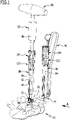
- eine beispielhafte perspektivische Darstellung eines Teils eines medizinischen Instrumentariums zum Implantieren eines Wirbelsäulenstabilisierungssystem beim Einsetzen eines Verbindungsstabs in Aufnahmen an Köpfen zweier Polyaxialschrauben;
- Figur 2:
- eine teilweise durchbrochene Ansicht in Richtung des Pfeils A in
Figur 1 ; - Figur 3:
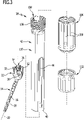
- eine Explosionsdarstellung eines schaft- oder hülsenförmigen Instruments, welches mit einem Kopf einer Polyaxialschraube temporär koppelbar ist;
- Figur 4:
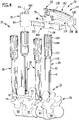
- eine perspektivische Gesamtansicht des Instrumentariums mit einem medizinischen Instrument zum temporären Koppeln mit zwei von insgesamt vier schaft- oder hülsenförmigen Instrumenten;
- Figur 5:
- eine perspektivische Ansicht des mit zwei schaft- oder hülsenförmigen Instrumenten gekoppelten medizinischen Instruments;
- Figur 6:
- eine Ansicht der Anordnung aus
Figur 5 in Richtung des Pfeils B; - Figur 7:
- eine Schnittansicht längs Linie 7-7 in
Figur 6 ; - Figur 8:
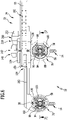
- eine Explosionsdarstellung des medizinischen Instruments zum temporären Koppeln mit zwei schaft- oder hülsenförmigen Instrumenten;
- Figur 9:
- eine teilweise durchbrochene Seitenansicht der Anordnung aus
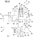
Figur 8 ; - Figur 10:
- eine Ansicht der Anordnung aus
Figur 9 in Richtung des Pfeils C; - Figur 11:
- eine perspektivische, teilweise Explosionsdarstellung der Anordnung aus
Figur 8 ; - Figur 12:
- eine Schnittansicht längs Linie 12-12 in
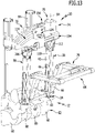
Figur 11 - Figur 13:
- eine perspektivische Gesamtansicht eines medizinischen Instrumentariums mit einem medizinischen Instrument zum temporären Koppeln mit zwei schaft- oder hülsenförmigen Instrumenten und einem Distraktor;
Figur 14;- eine Teilansicht der Anordnung aus
Figur 14 im Wesentlichen von der Gegenseite; - Figur 15:
- eine Anordnung ähnlich
Figur 14 beim Festlegen des Verbindungsstabs an einer Pedikelschraube bei einem voreingestellten Winkel der ersten und zweiten Kopplungseinrichtung des medizinischen Instruments relativ zueinander; - Figur 16:
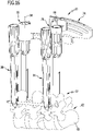
- eine perspektivische Gesamtansicht ähnlich
Figur 13 , jedoch ohne Distraktor; und - Figur 17:
- eine Ansicht ähnlich
Figur 16 beim Festlegen eines weiteren Verbindungsstabs an einer Pedikelschraube.
- Figure 1:
- an exemplary perspective representation of part of a medical instrument set for implanting a spinal column stabilization system when inserting a connecting rod into receptacles on the heads of two polyaxial screws;
- Figure 2:
- a partially broken view in the direction of arrow A in
figure 1 ; - Figure 3:
- an exploded view of a shaft- or sleeve-shaped instrument which can be temporarily coupled to a head of a polyaxial screw;
- Figure 4:
- a perspective overall view of the set of instruments with a medical instrument for temporary coupling with two of a total of four shaft-shaped or sleeve-shaped instruments;
- Figure 5:
- a perspective view of the medical instrument coupled to two shaft-shaped or sleeve-shaped instruments;
- Figure 6:
- a view of the arrangement
figure 5 in the direction of arrow B; - Figure 7:
- a sectional view taken along line 7-7 in
figure 6 ; - Figure 8:
- an exploded view of the medical instrument for temporary coupling with two shaft or sleeve-shaped instruments;
- Figure 9:
- a partially broken side view of the assembly
figure 8 ; - Figure 10:
- a view of the arrangement
figure 9 in the direction of arrow C; - Figure 11:
- a perspective, partially exploded view of the assembly
figure 8 ; - Figure 12:
- a sectional view taken along line 12-12 in
figure 11 ; - Figure 13:
- a perspective overall view of a set of medical instruments with a medical instrument for temporary coupling with two shaft-shaped or sleeve-shaped instruments and a distractor;
- Figure 14;
- a partial view of the assembly
figure 14 essentially from the opposite side; - Figure 15:
- an arrangement similar
figure 14 upon fixing the connecting rod to a pedicle screw at a preset angle of the first and second coupling means of the medical instrument relative to each other; - Figure 16:
- an overall perspective view similar
figure 13 , but without distractor; and - Figure 17:
- a view similar
figure 16 when attaching another connecting rod to a pedicle screw.
In den
Das Wirbelsäulenstabilisierungssystem 12 umfasst mehrere Knochenschrauben 14, die insbesondere in Form von Polyaxialschrauben ausgebildet sein können, mit einem langgestreckten Schaft 16, welcher mit einem Außengewinde 18 versehen ist und eine Schaftlängsachse 20 definiert, und einem Kopf 22, welcher einen Sitz 24 für ein kugeliges proximales Ende 26 des Schafts 16 aufweist, so dass der Kopf 22 relativ zum Schaft 16 um einen Mittelpunkt 28 des kugeligen Endes 26 verschwenkbar ist.The spinal
Der Kopf 22 weist eine im Wesentlichen U-förmige Stabaufnahme 30 auf, die zwischen zwei Wandabschnitten 32, welche mit Innengewindeabschnitten versehen sind, ausgebildet ist. In die Stabaufnahme 30 kann ein Verbindungsstab 34 des Wirbelsäulenstabilisierungssystems 12 eingesetzt und mit einer Fixierschraube 36 festgelegt werden, deren Außengewinde zu den Innengewindeabschnitten der Wandabschnitte 32 korrespondiert.The
Die Knochenschraube 14 kann insbesondere auch derart ausgebildet sein, dass mit der Fixierschraube 36 nicht nur der Verbindungsstab 34 am Kopf 22 festgelegt werden kann, sondern auch der Kopf 22 unbeweglich am kugeligen Ende 26 des Schafts 16 festlegbar ist.The
Das Instrumentarium 10 umfasst ferner mehrere schaft- oder hülsenförmige Instrumente 38, deren distales Ende 40 ausgebildet ist zum temporären Koppeln mit dem Kopf 22 in bekannter Weise. Das Instrument 38 kann insbesondere eine Außenhülse 42 umfassen, welche ausgehend vom Ende 40 einen sich parallel zu einer Längsachse der Außenhülse 42 erstreckenden Schlitz 44 aufweist. Der Schlitz 44 des Instruments 38 ist mit dem Kopf 22 so ausrichtbar, dass der an einem Einsetzinstrument 46 gehaltene Verbindungsstab 34, von der Seite her kommend in die Stabaufnahme 30 einführbar ist. Eine Einführöffnung für ein freies Ende 48 des Verbindungsstabs 34 ist insbesondere begrenzt durch die Wandabschnitte 32, den Sitz 24 sowie die Fixierschraube 36.The set of
Zum Festlegen des Verbindungsstabs 34 in der Stabaufnahme 30 dient ein Einschraubinstrument 50, welches durch die Außenhülse 42 hindurch an den Kopf 22 mit seinem distalen Ende heranführbar ist und an seinem distalen Ende ein Werkzeugelement 52 aufweist, welches korrespondierend zu einer in proximaler Richtung weisenden Werkzeugelementaufnahme 54 der Fixierschraube 36 ausgebildet ist. In den Figuren ist die Werkzeugelementaufnahme 54 beispielhaft in Form eines Innenvielrunds dargestellt. Alternativ sind die Werkzeugelementaufnahmen der Knochenschrauben 14 auch in Form eines Innenmehrkant oder eines Schlitzes möglich.A screw-in
Für die einfache Handhabung ist das Einschraubinstrument 50 proximalseitig mit einem Ratschengriff 56 ausgestattet, um einem Operateur auf einfache Weise das Anziehen der Fixierschraube am Kopf 22 zu ermöglichen. Insbesondere kann der Ratschengriff 56 mit einer Drehmomentbegrenzungseinrichtung 58 ausgestattet sein, um ein vordefiniertes Anzugsmoment der Fixierschraube 36 nicht zu überschreiten.For easy handling, the screw-in
Zur Implantation des Wirbelsäulenstabilisierungssystems 12 wird zunächst in die relativ zueinander zu positionierenden Wirbel 60 der Wirbelsäule 62 die erforderliche Anzahl von Knochenschrauben 14 eingeschraubt. Für eine optimale Stabilisierung der Wirbelsäule 62 werden beispielsweise beidseits der Dornfortsätze der Wirbel 60 Knochenschrauben 14 in die Pedikel der Wirbel 60 eingeschraubt.For the implantation of the spinal
Wie bereits beschrieben können die Köpfe 22 relativ zu den Schäften 16 der Knochenschrauben 14 zunächst um den Mittelpunkt 28 verschwenkt werden. Für eine einfache und insbesondere minimalinvasive Handhabung des Wirbelsäulenstabilisierungssystems 12 sowie des Instrumentariums 10 dienen die Instrumente 38. Diese werden mit den Köpfen 22 gekoppelt und bilden so Verlängerungen derselben, die aus dem Körper des Patienten herausragen.As already described, the
Um einen Abstand zwischen den Knochenschrauben 14 benachbarter Wirbel 60 gezielt einstellen zu können, kann das Instrumentarium 10 insbesondere einen Distraktor 64 mit zwei parallel zueinander verlaufenden Schenkeln 66 umfassen, deren distale Enden 68 mit den Instrumenten 38 im Bereich von deren distalen Enden 40 koppelbar sind. Proximale Enden der Schenkel 66 sind über einen Distraktionsbügel 70 gekoppelt, mit dem ein Abstand zwischen den Schenkeln 66 veränderbar und feststellbar ist.In order to be able to adjust a distance between the bone screws 14 of
Das Instrumentarium 10 umfasst ein weiteres Instrument 72 in Form eines Winkeleinstellers 74. Der Winkeleinsteller 74 ist ausgebildet zum temporären Koppeln mit zwei Instrumenten 38 und umfasst eine erste Kopplungseinrichtung 76 und eine zweite Kopplungseinrichtung 78. Die Kopplungseinrichtungen 76 und 78 sind relativ zueinander verschwenkbar am Instrument 72 angeordnet beziehungsweise ausgebildet. Des Weiteren sind die Kopplungseinrichtungen 76 und 78 relativ zueinander auch verschiebbar am Instrument 72 angeordnet beziehungsweise ausgebildet.The set of
Der Winkeleinsteller 74 umfasst einen plattenförmigen Grundkörper 80, an welchem die erste Kopplungseinrichtung 76 verschwenkbar um einen vom Grundkörper 80 räumlich entfernten Drehpunkt 82 geführt gehalten ist, welcher vorzugsweise mit dem Mittelpunkt 28 der Knochenschraube 14 übereinstimmt, mit welcher das mit der ersten Kopplungseinrichtung 76 gekoppelte Instrument 38 temporär verbunden ist. Insbesondere kann eine vom Winkeleinsteller 74 definierte Schwenkachse, um die die Kopplungseinrichtungen 76 und 78 relativ zueinander verschwenkbar sind, den Drehpunkt 82 umfassen beziehungsweise der Drehpunkt 82 liegt auf der Schwenkachse.The
Die zweite Kopplungseinrichtung 78 ist am Grundkörper 80 verschiebbar geführt gehalten.The
Die erste Kopplungseinrichtung 76 umfasst eine eine erste Kopplungseinrichtungslängsachse 84 definierende Aufnahme 86 für das Instrument 38. Die Aufnahme 86 ist in Form eines hülsenförmigen Haltebogens 88 ausgebildet, welcher im Wesentlichen C-förmig ist und einen Winkelbereich von mehr als 270° umschließt.The
Die zweite Kopplungseinrichtung 78 umfasst einen hülsenförmigen, in sich geschlossenen Haltering 90, welcher eine Aufnahme 92 für ein proximales Ende eines Instruments 38 bildet und eine zweite Kopplungseinrichtungslängsachse 94 definiert.The
Von einer Innenwand 96 des Haltebogens 88 stehen parallel zur ersten Kopplungseinrichtungslängsachse 84 und auf diese hin weisende, parallel verlaufende, streifenförmige Kopplungsvorsprünge 98 ab, welche korrespondierend zu Kopplungsausnehmungen 100 am Instrument 38 ausgebildet sind. Die Kopplungsausnehmungen 100 sind in Form von parallel zur ersten Kopplungseinrichtung 76 verlaufenden Längsnuten ausgebildet, die in radialer Richtung von der ersten Kopplungseinrichtungslängsachse 84 weg weisend geöffnet sind.Parallel to the first
Am Haltering 90 sind an einem proximalen Ende mehrere in Richtung auf die zweite Kopplungseinrichtungslängsachse 94 vorstehende Kopplungsvorsprünge 102 angeordnet, die ebenfalls in Kopplungsausnehmungen 100 am Instrument 38 eingreifen können. Außerdem sind auch von einer Innenwand 97 des Halterings 90 parallel zur zweiten Kopplungseinrichtungslängsachse 44 und auf diese hin weisend, parallel verlaufende, streifenförmige Kopplungsvorsprünge 99 abstehend ausgebildet, welche korrespondierend zu Kopplungsausnehmungen 100 am Instrument 38 ausgebildet sind.A plurality of
Die Kopplungsausnehmungen 100 sind an Verlängerungshülsen 104 ausgebildet, die mit proximalen, mit einem Außengewinde 106 versehenen Enden 108 der vom Instrument 38 umfassten, geschlitzten Außenhülsen 42 aufschraubbaren Kopplungshülsen 112 temporär koppelbar sind, und zwar insbesondere zum temporären Verbinden mit dem Winkeleinsteller 74.The coupling recesses 100 are formed on
Das Instrument 72 umfasst ferner eine erste Führungseinrichtung 114 zum Führen einer Bewegung der ersten Kopplungseinrichtung 76 längs eines Ausschnitts einer Kreisbahn 116. Die erste Führungseinrichtung 114 ist teilweise am Grundkörper 80 angeordnet beziehungsweise ausgebildet und umfasst zwei kreisbogenförmige Führungsschlitze 118 und 120, welche konzentrisch zueinander angeordnet sind.The
Um die erste Kopplungseinrichtung 76 in einer ersten Ausrichtstellung am Grundkörper 80 zu fixieren, ist eine erste Feststelleinrichtung 122 vorgesehen, und zwar in Form einer Klemmeinrichtung 124 mit einem ersten Klemmelement 126 und einem zweiten Klemmelement 127.In order to fix the
Das erste Klemmelement umfasst eine flache Platte 128, die auf ihrer einen Seite die Aufnahme 86 trägt und auf ihrer anderen Seite zwei senkrecht von ihr abstehende, den Führungsschlitz 118 durchsetzende bolzenförmige Verbindungsglieder 130, die jeweils mit einem ein Innengewinde umfassenden Sackloch 132 versehen sind. Das zweite Klemmelement 127 ist ebenfalls in Form einer Platte 134 ausgebildet, welche zwei Bohrungen 136 aufweist, die von Gewindeschäften 138 von Verbindungsschrauben durchsetzt sind, wobei die Gewindeschäfte 138 in die Sacklöcher 132 eingeschraubt sind.The first clamping element comprises a
Die beiden Platten 128 und 134 liegen auf zwei voneinander weg weisenden Seiten des Grundkörpers 80 an. Um die beiden Klemmelemente 126 und 127 so aufeinander bewegen zu können, dass die Feststelleinrichtung 122 die erste Ausrichtstellung einnimmt, ist ein erstes Klemmglied 142 vorgesehen mit einem bolzenförmigen Gewindeschaft 144 und einem T-förmigen Kopf 146. Der Gewindeschaft 144 durchsetzt eine Bohrung 148 der Platte 134 sowie den Führungsschlitz 120 und ist in eine Gewindebohrung 150 der Platte 128 eingeschraubt.The two
Durch Verdrehen des Klemmglieds 142 um seine Längsachse im Uhrzeigersinn werden die Platten 128 und 134 gegeneinander gezogen und klemmen den Grundkörper 80 zwischen sich. Verdreht man das erste Klemmglied 142 im Gegenuhrzeigersinn, so werden die Platten 128 und 134 gerade so weit gelöst, dass die erste Feststelleinrichtung 122 relativ zum Grundkörper 80 um eine Schwenkachse verschwenkbar ist, welche durch die Krümmung der Führungsschlitze 118 und 120 definiert wird. Wie bereits dargelegt, verläuft diese Schwenkachse idealerweise durch den Mittelpunkt 28.By rotating the clamping
Das erste Klemmglied 142 ist in Form einer Klemmschraube 143 ausgebildet. Diese ist von einer Justierstellung, in welcher die Klemmeinrichtung 124 relativ zum Grundkörper 80 bewegbar ist, in eine Klemmstellung bringbar, in welcher die Klemmeinrichtung 124 relativ zum Grundkörper 80 unbeweglich festgelegt ist.The
Das Instrument 72 umfasst ferner eine Verriegelungseinrichtung 152 zum Verriegeln der ersten Kopplungseinrichtung 76 am Grundkörper 80 in einer Grundstellung, in welcher die Kopplungseinrichtungslängsachsen 84 und 94 der Kopplungseinrichtungen 76 und 78 parallel zueinander ausgerichtet sind.The
Die Verriegelungseinrichtung 152 umfasst eine Rastverbindungseinrichtung 154 mit einem beweglichen ersten Rastglied 156 und einem zweiten Rastglied 158, welches durch eines der beiden Verbindungsglieder 130 gebildet ist. In der beispielhaft in
Das erste Rastglied 156 ist in Form eines um eine Schwenkachse 160, welche parallel zu Längsachsen der Verbindungsglieder 130 verläuft, verschwenkbar am Grundkörper 80 gelagerten Rasthebels 162 ausgebildet. Er umfasst eine Bohrung 164, die von einem zylindrischen Lagerstift 166 durchsetzt ist, welcher in eine Durchgangsbohrung 168 des Grundkörpers 80 eingesetzt ist. Der Rasthebel 162 ist in eine Rasthebelausnehmung 170 eingesetzt und vorspannend in der Grundstellung gehalten, und zwar mit einem Federelement 172 in Form einer als Druckfeder ausgebildeten Schraubenfeder, die in eine Sacklochbohrung 174, deren Längsachse quer zur Schwenkachse 160 verläuft, eingesetzt ist und gegen ein proximales Ende des Rasthebels 162 drückt.The
Am anderen Ende des Rasthebels 162 ist ein abstehender Vorsprung 176 angeordnet, welcher mit dem einen Verbindungsglied 130 in der Grundstellung in Eingriff bringbar ist, und zwar derart, dass der Vorsprung 176 das eine Verbindungsglied 130 hintergreift, welches in der Grundstellung zwischen dem Vorsprung 176 und der Schwenkachse 160 gehalten ist.Arranged at the other end of latching
Zum Lösen der Verriegelungseinrichtung 152 kann eine Betätigungsfläche 178, die vom Federelement 172 weg weisend am Rasthebel 162 mit einer Mehrzahl von Quernuten versehen ist, mit einer Lösekraft beaufschlagt werden, die das Federelement 172 komprimiert und den Rasthebel 162 so um die Schwenkachse 160 verschwenkt, dass der Vorsprung 176 das mit ihm in der Grundstellung zusammenwirkende Verbindungsglied 130 freigibt. Ist ferner die erste Klemmeinrichtung 124 gelöst, nimmt sie also die Justierstellung ein, so kann die erste Feststelleinrichtung 122 in den Führungsschlitzen 118 und 120 um die Schwenkachse des Instruments 72 bewegt werden.To release locking
Um zwischen den Kopplungseinrichtungslängsachsen 84 und 94 einen Winkel 180 einstellen und anzeigen zu können, ist am Winkeleinsteller 74 ferner eine Anzeigeeinrichtung 182 ausgebildet. Sie umfasst eine Mehrzahl auf einer konzentrisch zur Schwenkachse des Instruments 72 verlaufenden Seitenfläche 184 des Grundkörpers 80 ausgebildeten Winkelmarkierungen 186, die in Form flacher schmaler Nuten ausgebildet sind.In order to be able to set and display an
An der ersten Kopplungseinrichtung 76 ist ein Anzeigeglied 188 ausgebildet, und zwar in Form eines von der Platte 128 an einer Seitenkante derselben vorstehenden Vorsprungs 190, welcher auf die Winkelmarkierungen 186 hin weist. Optional kann auch am zweiten Klemmelement 127 ein weiteres Anzeigeglied angeordnet oder ausgebildet sein. So ist bei dem in den Figuren dargestellten Ausführungsbeispiel des Winkeleinstellers 74 auch auf der Platte 134 ein dem Anzeigeglied 188 entsprechendes Anzeigeglied 192 angeordnet.An
Der Winkeleinsteller 74 umfasst ferner eine zweite Führungseinrichtung 194 zum Führen einer Bewegung der zweiten Kopplungseinrichtung 78 längs einer geradlinigen Bahn. Sie ist am Grundkörper 80 ausgebildet beziehungsweise angeordnet und umfasst zwei Führungskörper 196 mit jeweils einer in Form einer Durchbrechung ausgebildeten Führungsaufnahme 198, welche eine gemeinsame Längsachse 200 definieren. Die beiden Führungskörper 196 sind beabstandet voneinander auf einer Seitenfläche des Grundkörpers 80 angeordnet, die von der Seitenfläche mit den Winkelmarkierungen 186 weg weist.The
Die zweite Kopplungseinrichtung 78 ist an einem stab- oder schaftförmigen Führungsglied 202 angeordnet, und zwar an einem Ende desselben. Das Führungsglied 202 weist einen unrunden, insbesondere vieleckigen Querschnitt auf, welcher im Wesentlichen korrespondierend zu einem Querschnitt der Führungsaufnahmen 198 ausgebildet ist, so dass das Führungsglied 202 parallel zur Längsachse 200 in der Führungsaufnahme 198 verschiebbar ist.The
Der Haltering 90 ist am Führungsglied 202 seitlich angeordnet, so dass die Kopplungseinrichtungslängsachsen 84 und 94 eine gemeinsame Ebene definieren, die senkrecht zur Schwenkachse 160 verläuft.Retaining
Um die zweite Kopplungseinrichtung 78 in einer zweiten Ausrichtstellung am Grundkörper 80 zu fixieren, umfasst das Instrument 72 ferner eine zweite Feststelleinrichtung 204, die ebenfalls in Form einer Klemmeinrichtung 206 ausgebildet ist. Sie umfasst ein zweites Klemmglied 208 zum klemmenden Fixieren des Führungsglieds 202 am Grundkörper 80.In order to fix the
Das zweite Klemmglied 208 ist in Form einer Klemmschraube 210 ausgebildet, welche eine Gewindebohrung 212 an einem der Führungskörper 196 durchsetzt, deren Längsachse quer zur Längsachse 200 verläuft. Ein Gewindeschaft 214 der Klemmschraube 210 ist in die Gewindebohrung 212 eingeschraubt und drückt mit einem freien Schaftende 216 in der zweiten Ausrichtstellung gegen das Führungsglied 202.The
Das Führungsglied 202 weist eine parallel zur Längsachse 200 verlaufende nutförmige Führungsvertiefung 218 auf, in die das Schaftende 216 eintaucht.The
Aufeinander zu weisende innere Seitenflächen am Ende der Führungsvertiefung 218 bilden Endanschläge 220, die eine Verschiebebewegung des Führungsglieds 202 relativ zum Grundkörper 80 begrenzen.Inner side faces facing each other at the end of the
Zum Betätigen der zweiten Feststelleinrichtung umfasst die Klemmschraube 210 einen T-förmigen Kopf 222, so dass durch eine Verdrehung der Klemmschraube 210 im Uhrzeigersinn das Schaftende 216 in Richtung auf das Führungsglied 202 hin und bei einer Bewegung im Gegenuhrzeigersinn vom Führungsglied 202 weg bewegt werden kann.To actuate the second locking device, the clamping
Nachfolgend wird die Funktionsweise des Instrumentariums 10 kurz anhand der
In einem ersten Schritt werden, wie schematisch in
Die Verbindungsstäbe 34 können nun an jeweils einer Knochenschraube 14 mit dem durch die Außenhülse 42 eingeführten Einschraubinstrument 50 vorfixiert werden.The connecting
Um einen Winkel zwischen Längsachsen der Instrumente 38, die mit Knochenschrauben 14, welche in benachbarte Wirbel 60 eingeschraubt sind, verbunden sind, in gewünschter Weise auszurichten, wird, wie in
Nun kann das Instrument 72 mit den beiden Instrumenten 38 in der beschriebenen Weise gekoppelt werden, und zwar wie in den
Der Winkeleinsteller 74 befindet sich zunächst in der Grundstellung, sodass die Kopplungseinrichtungslängsachsen 84 und 94 parallel zueinander ausgerichtet sind.The
Um einen gewünschten Winkel 180 zwischen den Kopplungseinrichtungslängsachsen 84 und 94 einzustellen, wird zunächst der Rasthebel 162 betätigt durch Beaufschlagen der Betätigungsfläche 178 mit einer Betätigungskraft. Der Vorsprung 176 gibt dann das mit ihm in Eingriff stehende Verbindungsglied 130 frei und die erste Kopplungseinrichtung 76 kann relativ zur zweiten Kopplungseinrichtung 78 verschwenkt beziehungsweise längs der durch die erste Führungseinrichtung 114 definierten Führungsbahn bewegt werden.In order to set a desired
Die erste Feststelleinrichtung 122 ist zunächst gelockert und die Kopplungseinrichtungen 76 und 78 werden so weit verschwenkt, bis der gewünschte Winkel 180 auf der Anzeigeeinrichtung 182 ablesbar ist.The
Nun kann mit der Klemmeinrichtung 124 die erste Kopplungseinrichtung 76 in der ersten Ausrichtstellung festgelegt werden. Dazu wird die Klemmschraube 143 im Uhrzeigersinn verdreht, bis die Klemmeinrichtung 124 den Grundkörper 80 klemmend zwischen sich hält.The
Falls eine weitere Distraktion der benachbarten Wirbel 60 erforderlich ist können die erste und zweite Kopplungseinrichtung 76, 80 mit der zweiten Führungseinrichtung 194 in der beschriebenen Weise relativ zueinander parallel zur Längsachse 200 verschoben werden. Optional kann der oben beschriebene Distraktor 64 eingesetzt werden, welcher direkt mit den Enden 40 der Instrumente 38 koppelbar ist, um die Knochenschrauben 14 in einer durch den Verbindungsstab 34 definierten Richtung voneinander weg oder aufeinander zu zu bewegen.If further distraction of the
In der beschriebenen Weise kann eine beliebige Zahl von Knochenschrauben 14 mit Wirbeln 60 verschraubt werden. Optional können mit dem Winkeleinsteller 74 auch Instrumente 38 relativ zueinander ausgerichtet werden, die mit Knochenschrauben 14 gekoppelt sind, die am selben Wirbel 60 festgelegt sind.Any number of bone screws 14 can be screwed to
- 1010
- Instrumentariuminstruments
- 1212
- Wirbelsäulenstabilisierungssystemspinal stabilization system
- 1414
- Knochenschraubebone screw
- 1616
- Schaftshaft
- 1818
- Außengewindeexternal thread
- 2020
- Schaftlängsachselongitudinal axis of the shaft
- 2222
- Kopfhead
- 2424
- SitzSeat
- 2626
- EndeEnd
- 2828
- MittelpunktFocus
- 3030
- Stabaufnahmepole mount
- 3232
- Wandabschnittwall section
- 3434
- Verbindungsstabconnecting rod
- 3636
- Fixierschraubefixing screw
- 3838
- Instrumentinstrument
- 4040
- EndeEnd
- 4242
- Außenhülseouter sleeve
- 4444
- Schlitzslot
- 4646
- Einsetzinstrumentinsertion tool
- 4848
- EndeEnd
- 5050
- Einschraubinstrumentscrew-in instrument
- 5252
- Werkzeugelementtool item
- 5454
- Werkzeugelementaufnahmetool element holder
- 5656
- Ratschengriffratchet handle
- 5858
- Drehmomentbegrenzungseinrichtungtorque limiting device
- 6060
- Wirbelwhirl
- 6262
- Wirbelsäulespine
- 6464
- Distraktordistractor
- 6666
- Schenkelleg
- 6868
- EndeEnd
- 7070
- Distraktionsbügeldistraction bar
- 7272
- Instrumentinstrument
- 7474
- Winkeleinstellerangle adjuster
- 7676
- erste Kopplungseinrichtungfirst coupling device
- 7878
- zweite Kopplungseinrichtungsecond coupling device
- 8080
- Grundkörperbody
- 8282
- Drehpunktpivot point
- 8484
- erste Kopplungseinrichtungslängsachsefirst coupler longitudinal axis
- 8686
- Aufnahmerecording
- 8888
- Haltebogentie
- 9090
- Halteringretaining ring
- 9292
- Aufnahmerecording
- 9494
- zweite Kopplungseinrichtungslängsachsesecond coupling device longitudinal axis
- 9696
- Innenwandinner wall
- 9797
- Innenwandinner wall
- 9898
- Kopplungsvorsprungcoupling tab
- 9999
- Kopplungsvorsprungcoupling tab
- 100100
- Kopplungsausnehmungcoupling recess
- 102102
- Kopplungsvorsprungcoupling tab
- 103103
- Wandflächewall surface
- 104104
- Verlängerungshülseextension sleeve
- 106106
- Außengewindeabschnittmale thread section
- 108108
- EndeEnd
- 110110
- Hülsesleeve
- 112112
- Kopplungshülsecoupling sleeve
- 114114
- erste Führungseinrichtungfirst guide device
- 116116
- Kreisbahncircular path
- 118118
- Führungsschlitzguide slot
- 120120
- Führungsschlitzguide slot
- 122122
- erste Feststelleinrichtungfirst locking device
- 124124
- Klemmeinrichtungclamping device
- 126126
- erstes Klemmelementfirst clamping element
- 127127
- zweites Klemmelementsecond clamping element
- 128128
- Platteplate
- 130130
- Verbindungsgliedlink
- 132132
- Sacklochblind hole
- 134134
- Platteplate
- 136136
- Bohrungdrilling
- 138138
- Gewindeschaftthreaded shank
- 140140
- Verbindungsschraubeconnecting screw
- 142142
- erstes Klemmgliedfirst clamping member
- 143143
- Klemmschraubeclamping screw
- 144144
- Gewindeschaftthreaded shank
- 146146
- Kopfhead
- 148148
- Bohrungdrilling
- 150150
- Gewindebohrungthreaded hole
- 152152
- Verriegelungseinrichtunglocking device
- 154154
- Rastverbindungseinrichtungsnap-in connection device
- 156156
- erstes Rastgliedfirst locking element
- 158158
- zweites Rastgliedsecond locking member
- 160160
- Schwenkachsepivot axis
- 162162
- Rasthebellocking lever
- 164164
- Bohrungdrilling
- 166166
- Lagerstiftbearing pin
- 168168
- Durchgangsbohrungthrough hole
- 170170
- Rasthebelausnehmunglocking lever recess
- 172172
- Federelementspring element
- 174174
- Sacklochbohrungblind hole
- 176176
- Vorsprunghead Start
- 178178
- Bestätigungsflächeconfirmation area
- 180180
- Winkelangle
- 182182
- Anzeigeeinrichtungdisplay device
- 184184
- Seitenflächeside face
- 186186
- Winkelmarkierungangle mark
- 188188
- Anzeigegliedindicator
- 190190
- Vorsprunghead Start
- 192192
- Anzeigegliedindicator
- 194194
- zweite Führungseinrichtungsecond guide device
- 196196
- Führungskörperguide body
- 198198
- Führungsaufnahmelead recording
- 200200
- Längsachselongitudinal axis
- 202202
- Führungsgliedleader
- 204204
- zweite Feststelleinrichtungsecond locking device
- 206206
- Klemmeinrichtungclamping device
- 208208
- zweites Klemmgliedsecond clamping member
- 210210
- Klemmschraubeclamping screw
- 212212
- Gewindebohrungthreaded hole
- 214214
- Gewindeschaftthreaded shank
- 216216
- Schaftendeshaft end
- 218218
- Führungsvertiefungleadership deepening
- 220220
- Endanschlagend stop
- 222222
- Kopfhead
Claims (15)
- Medical instrument (72) for temporarily coupling to at least two shank-or sleeve-shaped instruments (38), comprising a first coupling device (76) for temporarily coupling to a first shank- or sleeve-shaped instrument (38) and a second coupling device (78) for coupling to a second shank- or sleeve-shaped instrument (38), wherein the first coupling device (76) and the second coupling device (78) are arranged or formed so as to be pivotable relative to each other, which medical instrument comprises a main body (80) on which the first coupling device (76) is guided and held so as to be pivotable about a point of rotation (82) that, in particular, is spatially remote from the main body (80), which medical instrument comprises a first guide device (114) for guiding a movement of the first coupling device (76) along a circular path (116), wherein the first guide device (114) is arranged or formed at least partially on the main body (80), characterized in that the first guide device (114) comprises two or more circular arc shaped guide slots (118, 120).
- Medical instrument in accordance with Claim 1, characterized in thata) the first coupling device (76) and the second coupling device (78) are arranged or formed so as to be displaceable relative to each other
and/orb) the second coupling device (78) is displaceably guided and held on the main body (80). - Medical instrument in accordance with any one of the preceding Claims, characterized in that the first coupling device (76) and/or the second coupling device (78) are configured in the form of a receiver (86, 92) for a shank- or sleeve-shaped instrument (38), which defines a coupling device longitudinal axis (84, 94).
- Medical instrument in accordance with Claim 3, characterized in thata) the receivers (86, 92) are configured in the form of retaining rings or retaining arcs (88)
and/orb) at least one protruding coupling projection (98, 102) is arranged or formed at the receivers (86, 92) for coupling to a shank- or sleeve-shaped instrument (38) in a non-positive-and/or positive-locking manner,
wherein, in particular, the at least one coupling projection (98, 102) is formed projecting from an inner wall face (96, 103) toward the coupling device longitudinal axis (84). - Medical instrument in accordance with any one of the preceding Claims, characterized by two circular arc shaped guide slots (118, 120) arranged concentrically to each other.
- Medical instrument in accordance with any one of the preceding Claims, characterized by a first fixing device (122) for fixing the first coupling device (76) in a first orientation on the main body (80).
- Medical instrument in accordance with Claim 6, characterized in that the first fixing device (122) is configured in the form of a clamping device (124).
- Medical instrument in accordance with Claim 7, characterized in that the clamping device comprises first and second clamping elements (126, 127) that are coupled to each other by connecting members (130) penetrating the at least one guide slot (118) and that comprise a first clamping member (142) for moving the first and second clamping elements (126, 127) toward each other.
- Medical instrument in accordance with Claim 8, characterized in thata) the first clamping member (142) is configured in the form of a clamping screw (143) which at least partially penetrates the at least one guide slot (120) and is able to be brought from an adjusting position into a clamping position and vice versa
and/orb) the first clamping element (126) comprises or bears the first receiver (86). - Medical instrument in accordance with any one of the preceding Claims, characterized by a locking device (152) for locking the first coupling device (76) on the main body (80) in a normal position in which the coupling device longitudinal axes (84, 94) of the at least two coupling devices (76, 78) are aligned in parallel to each other.
- Medical instrument in accordance with Claim 10, characterized in that the locking device (152) comprises a latching connecting device (154) having a moveable first latching member (156) and a second latching member (158), and in that the first and the second latching member (156, 158) are engaged in a non-positive- and/or positive-locking manner in the normal position and are disengaged in a release position,wherein, in particular, the first latching member (156) is configured in the form of a latching lever (162) that is displaceably and/or pivotably mounted on the main body (80) and which has a projection (176) or a recess which is engaged in the normal position with a corresponding recess or a corresponding projection (130) on the first coupling device (76),wherein, further in particular, the first latching member (156) is mounted so as to be pivotable about a pivot axis (160) which runs transversely, in particular perpendicularly, to the coupling device longitudinal axis (84, 94) of the first and/or second coupling device (76, 78).
- Medical instrument in accordance with any one of Claims 3 to 11, characterized by a display device (182) for displaying an angle (180) between the coupling device longitudinal axes (84, 94) of the at least two coupling devices (76, 78).
- Medical instrument in accordance with Claim 12, characterized in that the display device (182) comprises angle markings (186) on the main body (80), and a display member, arranged or formed on the first coupling device (76), which points to the angle markings (186) wherein, in particular, the display member (188) is arranged or formed on the first and/or second clamping element (126, 127).
- Medical instrument in accordance with any one of the preceding Claims, characterized bya) a second guide device (194) for guiding a movement of the second coupling device (78) along a linear path,wherein, in particular, the second guide device (194) is formed on the main body (80) and comprises at least one guide receiver (198), in particular two,wherein, further in particular, the second coupling device (78) comprises a rod- or shank-shaped guide member (202) which is guided and held in or at the at least one guide receiver (198),
and/orb) a second fixing device for fixing the second coupling device (78) in a second orientation (204) on the main body (80), wherein, in particular, the second fixing device (204) is configured in the form of a clamping device (206),
wherein, further in particular, the second clamping device (206) comprises at least one second clamping member (208) for fixing the guide member (202) on the main body (80) in a clamping manner, which second clamping member (208), in particular, is configured in the form of a clamping screw (210) which penetrates the at least one guide receiver (198) and pushes against the guide member (202) in the second orientation with a free shank end (216) of a clamping screw shank (214), in particular in the region of a groove-shaped guide recess (218), which guide recess (218), in particular, defines end stops (220) for a displacement movement of the guide member (202) relative to the main body (80). - Medical instrumentarium (10) for implanting a spinal column stabilization system (12), comprising at least two shank- or sleeve-shaped instruments (38), characterized in that the instrumentarium (10) further comprises an instrument (72) in accordance with any one of the preceding Claims.
Applications Claiming Priority (2)
| Application Number | Priority Date | Filing Date | Title |
|---|---|---|---|
| DE102015120955.1A DE102015120955A1 (en) | 2015-12-02 | 2015-12-02 | Medical instrument and medical instrument |
| PCT/EP2016/079616 WO2017093497A1 (en) | 2015-12-02 | 2016-12-02 | Medical instrument and medical equipment |
Publications (2)
| Publication Number | Publication Date |
|---|---|
| EP3383291A1 EP3383291A1 (en) | 2018-10-10 |
| EP3383291B1 true EP3383291B1 (en) | 2022-06-22 |
Family
ID=57460540
Family Applications (1)
| Application Number | Title | Priority Date | Filing Date |
|---|---|---|---|
| EP16805150.6A Active EP3383291B1 (en) | 2015-12-02 | 2016-12-02 | Medical instrument and medical equipment |
Country Status (6)
| Country | Link |
|---|---|
| US (1) | US10588673B2 (en) |
| EP (1) | EP3383291B1 (en) |
| JP (1) | JP6863986B2 (en) |
| CN (1) | CN108697443B (en) |
| DE (1) | DE102015120955A1 (en) |
| WO (1) | WO2017093497A1 (en) |
Families Citing this family (7)
| Publication number | Priority date | Publication date | Assignee | Title |
|---|---|---|---|---|
| WO2012128825A1 (en) * | 2011-03-24 | 2012-09-27 | Jackson Roger P | Polyaxial bone anchor with compound articulation and pop-on shank |
| US11484349B2 (en) * | 2017-02-17 | 2022-11-01 | Warsaw Orthopedic, Inc. | Surgical system and method |
| AU2018324017B2 (en) | 2017-08-30 | 2020-08-20 | Zimmer Biomet Spine, Inc. | Dynamic stabilization system |
| CN107736925B (en) * | 2017-11-14 | 2020-03-24 | 山东威高骨科材料股份有限公司 | Sleeve, auxiliary device for installing connecting rod and installation method of connecting rod |
| EP3517062B1 (en) | 2018-01-26 | 2021-03-17 | Aesculap AG | Spinal repositioning instrument and spinal repositioning system |
| EP3636185B1 (en) * | 2018-10-09 | 2023-12-06 | Biedermann Technologies GmbH & Co. KG | System for correcting the position of bones, bone parts or vertebrae |
| US11678912B2 (en) * | 2019-09-24 | 2023-06-20 | Astura Medical Inc | Minimally invasive compressor / distractor |
Family Cites Families (16)
| Publication number | Priority date | Publication date | Assignee | Title |
|---|---|---|---|---|
| CN2074630U (en) * | 1990-10-10 | 1991-04-10 | 黄克勤 | Single arm bridge frame spring outer fixer for fracture |
| CN2406623Y (en) * | 2000-01-27 | 2000-11-22 | 陈国强 | Multifunctional instrument for stereoscopic directional operation on cranium and brain |
| US20080077155A1 (en) * | 2006-09-25 | 2008-03-27 | Jennifer Diederich | System and method for displacement of bony structures |
| US8197488B2 (en) * | 2006-10-16 | 2012-06-12 | Depuy Spine, Inc. | Automatic locking casper distractor |
| CN201029934Y (en) * | 2007-01-24 | 2008-03-05 | 辛兆芹 | Microwave knife mechanical guiding arm |
| CN101791249B (en) * | 2010-01-28 | 2012-09-26 | 韩增灿 | Precornu puncture direction finder |
| US9345547B2 (en) * | 2011-04-18 | 2016-05-24 | Warsaw Orthopedic, Inc. | Apparatus and method for sizing a connecting element for positioning along a bone structure |
| TWI448790B (en) * | 2011-05-13 | 2014-08-11 | Chi Mei Corp | Liquid crystal alignment film and liguid crystal display element |
| US8951257B2 (en) * | 2012-02-15 | 2015-02-10 | Warsaw Orthopedic, Inc. | Spinal correction system and method |
| JP6175129B2 (en) * | 2012-04-17 | 2017-08-02 | アルファテック スパイン, インコーポレイテッド | Instruments and methods for spinal cord compression and traction |
| DE102012107056A1 (en) | 2012-08-01 | 2014-05-15 | Aesculap Ag | Surgical instruments |
| US20140107659A1 (en) * | 2012-10-12 | 2014-04-17 | Alphatec Spine, Inc. | In situ rod measuring instrument and method of use |
| CN203369957U (en) * | 2013-07-19 | 2014-01-01 | 马台 | Femoral head center navigator |
| DE102013108362A1 (en) * | 2013-08-02 | 2015-02-05 | Aesculap Ag | Medical instrument for holding and manipulating a surgical fastener and spinal stabilization system |
| US9402660B2 (en) * | 2013-09-05 | 2016-08-02 | Warsaw Orthopedic, Inc. | Surgical instrument and method |
| DE102013111683A1 (en) | 2013-10-23 | 2015-04-23 | Aesculap Ag | Spine stabilization system, medical instrumentation and medical device for aligning medical instruments in parallel |
-
2015
- 2015-12-02 DE DE102015120955.1A patent/DE102015120955A1/en not_active Withdrawn
-
2016
- 2016-12-02 CN CN201680071130.1A patent/CN108697443B/en active Active
- 2016-12-02 WO PCT/EP2016/079616 patent/WO2017093497A1/en active Application Filing
- 2016-12-02 JP JP2018528693A patent/JP6863986B2/en active Active
- 2016-12-02 EP EP16805150.6A patent/EP3383291B1/en active Active
-
2018
- 2018-05-29 US US15/990,966 patent/US10588673B2/en active Active
Also Published As
| Publication number | Publication date |
|---|---|
| US10588673B2 (en) | 2020-03-17 |
| WO2017093497A1 (en) | 2017-06-08 |
| DE102015120955A1 (en) | 2017-06-08 |
| US20180271566A1 (en) | 2018-09-27 |
| CN108697443A (en) | 2018-10-23 |
| JP2018537195A (en) | 2018-12-20 |
| EP3383291A1 (en) | 2018-10-10 |
| CN108697443B (en) | 2021-12-21 |
| JP6863986B2 (en) | 2021-04-21 |
Similar Documents
| Publication | Publication Date | Title |
|---|---|---|
| EP3383291B1 (en) | Medical instrument and medical equipment | |
| EP3454767B1 (en) | Medical instrument for provisionally fastening a polyaxial pedicle screw | |
| EP2832308B1 (en) | Medical instrument for holding and handling a surgical fastening element and spine stabilising system | |
| DE69723108T2 (en) | ADJUSTABLE OSTEOSYNTHESIS DEVICE FOR THE SPINE AND POSITIONING TOOL | |
| EP2266483B1 (en) | Surgical bone anchoring device and spinal column fixation system | |
| EP2233097B1 (en) | Instrument set for inserting a stabilisation system into the spine of a body | |
| EP3023065B1 (en) | Pedicle screw system and spinal column-stabilizing system | |
| EP3117787A1 (en) | Pedicle screw with tulip | |
| EP1551320A1 (en) | Orthopedic fixation device | |
| EP2829244A2 (en) | Instrument set for percutaneous spinal stabilisation with the aid of pedicle screws and rods | |
| WO2002054965A1 (en) | Connector element for bone rods or spinal rods | |
| WO2003011156A1 (en) | Connecting element | |
| EP3023066B1 (en) | Pedicle screw system and spinal column-stabilizing system | |
| EP2460481A1 (en) | Fusion implant for facet joints | |
| EP3075330B1 (en) | Medical guiding device | |
| EP3035877B1 (en) | Surgical instrument for manipulating, positioning and fixing a surgical rod in relation to an implant | |
| EP1269929A1 (en) | Connection system for the spinal fusion of the lumbar column | |
| DE102004056091B4 (en) | Orthopedic fixation device and orthopedic fixation system | |
| EP3592253B1 (en) | Medical saw jig system | |
| DE102022108980A1 (en) | Osteosynthesis device, in particular for treating the spine, and fastening system for the same | |
| DE202004018037U1 (en) | Device to be used for securing bone stabilizing element to bone screw, comprising single element for adjusting and fixing | |
| WO2021083845A1 (en) | Medical decoupling instrument | |
| EP3420990A1 (en) | Expansion device for a bone anchor | |
| DE202004014768U1 (en) | Device for distraction of vertebral bodies during operation, comprising one holding arm attached to movable sleeve | |
| DE102014100362A1 (en) | Medical instrument, medical instrumentation and spine stabilization system |
Legal Events
| Date | Code | Title | Description |
|---|---|---|---|
| STAA | Information on the status of an ep patent application or granted ep patent |
Free format text: STATUS: UNKNOWN |
|
| STAA | Information on the status of an ep patent application or granted ep patent |
Free format text: STATUS: THE INTERNATIONAL PUBLICATION HAS BEEN MADE |
|
| PUAI | Public reference made under article 153(3) epc to a published international application that has entered the european phase |
Free format text: ORIGINAL CODE: 0009012 |
|
| STAA | Information on the status of an ep patent application or granted ep patent |
Free format text: STATUS: REQUEST FOR EXAMINATION WAS MADE |
|
| 17P | Request for examination filed |
Effective date: 20180629 |
|
| AK | Designated contracting states |
Kind code of ref document: A1 Designated state(s): AL AT BE BG CH CY CZ DE DK EE ES FI FR GB GR HR HU IE IS IT LI LT LU LV MC MK MT NL NO PL PT RO RS SE SI SK SM TR |
|
| AX | Request for extension of the european patent |
Extension state: BA ME |
|
| DAV | Request for validation of the european patent (deleted) | ||
| DAX | Request for extension of the european patent (deleted) | ||
| GRAP | Despatch of communication of intention to grant a patent |
Free format text: ORIGINAL CODE: EPIDOSNIGR1 |
|
| STAA | Information on the status of an ep patent application or granted ep patent |
Free format text: STATUS: GRANT OF PATENT IS INTENDED |
|
| INTG | Intention to grant announced |
Effective date: 20220110 |
|
| GRAS | Grant fee paid |
Free format text: ORIGINAL CODE: EPIDOSNIGR3 |
|
| GRAA | (expected) grant |
Free format text: ORIGINAL CODE: 0009210 |
|
| STAA | Information on the status of an ep patent application or granted ep patent |
Free format text: STATUS: THE PATENT HAS BEEN GRANTED |
|
| AK | Designated contracting states |
Kind code of ref document: B1 Designated state(s): AL AT BE BG CH CY CZ DE DK EE ES FI FR GB GR HR HU IE IS IT LI LT LU LV MC MK MT NL NO PL PT RO RS SE SI SK SM TR |
|
| REG | Reference to a national code |
Ref country code: GB Ref legal event code: FG4D Free format text: NOT ENGLISH |
|
| REG | Reference to a national code |
Ref country code: CH Ref legal event code: EP |
|
| REG | Reference to a national code |
Ref country code: DE Ref legal event code: R096 Ref document number: 502016014998 Country of ref document: DE |
|
| REG | Reference to a national code |
Ref country code: AT Ref legal event code: REF Ref document number: 1499282 Country of ref document: AT Kind code of ref document: T Effective date: 20220715 |
|
| REG | Reference to a national code |
Ref country code: IE Ref legal event code: FG4D Free format text: LANGUAGE OF EP DOCUMENT: GERMAN |
|
| REG | Reference to a national code |
Ref country code: LT Ref legal event code: MG9D |
|
| REG | Reference to a national code |
Ref country code: NL Ref legal event code: MP Effective date: 20220622 |
|
| PG25 | Lapsed in a contracting state [announced via postgrant information from national office to epo] |
Ref country code: SE Free format text: LAPSE BECAUSE OF FAILURE TO SUBMIT A TRANSLATION OF THE DESCRIPTION OR TO PAY THE FEE WITHIN THE PRESCRIBED TIME-LIMIT Effective date: 20220622 Ref country code: NO Free format text: LAPSE BECAUSE OF FAILURE TO SUBMIT A TRANSLATION OF THE DESCRIPTION OR TO PAY THE FEE WITHIN THE PRESCRIBED TIME-LIMIT Effective date: 20220922 Ref country code: LT Free format text: LAPSE BECAUSE OF FAILURE TO SUBMIT A TRANSLATION OF THE DESCRIPTION OR TO PAY THE FEE WITHIN THE PRESCRIBED TIME-LIMIT Effective date: 20220622 Ref country code: HR Free format text: LAPSE BECAUSE OF FAILURE TO SUBMIT A TRANSLATION OF THE DESCRIPTION OR TO PAY THE FEE WITHIN THE PRESCRIBED TIME-LIMIT Effective date: 20220622 Ref country code: GR Free format text: LAPSE BECAUSE OF FAILURE TO SUBMIT A TRANSLATION OF THE DESCRIPTION OR TO PAY THE FEE WITHIN THE PRESCRIBED TIME-LIMIT Effective date: 20220923 Ref country code: FI Free format text: LAPSE BECAUSE OF FAILURE TO SUBMIT A TRANSLATION OF THE DESCRIPTION OR TO PAY THE FEE WITHIN THE PRESCRIBED TIME-LIMIT Effective date: 20220622 Ref country code: BG Free format text: LAPSE BECAUSE OF FAILURE TO SUBMIT A TRANSLATION OF THE DESCRIPTION OR TO PAY THE FEE WITHIN THE PRESCRIBED TIME-LIMIT Effective date: 20220922 |
|
| PG25 | Lapsed in a contracting state [announced via postgrant information from national office to epo] |
Ref country code: RS Free format text: LAPSE BECAUSE OF FAILURE TO SUBMIT A TRANSLATION OF THE DESCRIPTION OR TO PAY THE FEE WITHIN THE PRESCRIBED TIME-LIMIT Effective date: 20220622 Ref country code: LV Free format text: LAPSE BECAUSE OF FAILURE TO SUBMIT A TRANSLATION OF THE DESCRIPTION OR TO PAY THE FEE WITHIN THE PRESCRIBED TIME-LIMIT Effective date: 20220622 |
|
| PG25 | Lapsed in a contracting state [announced via postgrant information from national office to epo] |
Ref country code: NL Free format text: LAPSE BECAUSE OF FAILURE TO SUBMIT A TRANSLATION OF THE DESCRIPTION OR TO PAY THE FEE WITHIN THE PRESCRIBED TIME-LIMIT Effective date: 20220622 |
|
| PG25 | Lapsed in a contracting state [announced via postgrant information from national office to epo] |
Ref country code: SM Free format text: LAPSE BECAUSE OF FAILURE TO SUBMIT A TRANSLATION OF THE DESCRIPTION OR TO PAY THE FEE WITHIN THE PRESCRIBED TIME-LIMIT Effective date: 20220622 Ref country code: SK Free format text: LAPSE BECAUSE OF FAILURE TO SUBMIT A TRANSLATION OF THE DESCRIPTION OR TO PAY THE FEE WITHIN THE PRESCRIBED TIME-LIMIT Effective date: 20220622 Ref country code: RO Free format text: LAPSE BECAUSE OF FAILURE TO SUBMIT A TRANSLATION OF THE DESCRIPTION OR TO PAY THE FEE WITHIN THE PRESCRIBED TIME-LIMIT Effective date: 20220622 Ref country code: PT Free format text: LAPSE BECAUSE OF FAILURE TO SUBMIT A TRANSLATION OF THE DESCRIPTION OR TO PAY THE FEE WITHIN THE PRESCRIBED TIME-LIMIT Effective date: 20221024 Ref country code: ES Free format text: LAPSE BECAUSE OF FAILURE TO SUBMIT A TRANSLATION OF THE DESCRIPTION OR TO PAY THE FEE WITHIN THE PRESCRIBED TIME-LIMIT Effective date: 20220622 Ref country code: EE Free format text: LAPSE BECAUSE OF FAILURE TO SUBMIT A TRANSLATION OF THE DESCRIPTION OR TO PAY THE FEE WITHIN THE PRESCRIBED TIME-LIMIT Effective date: 20220622 Ref country code: CZ Free format text: LAPSE BECAUSE OF FAILURE TO SUBMIT A TRANSLATION OF THE DESCRIPTION OR TO PAY THE FEE WITHIN THE PRESCRIBED TIME-LIMIT Effective date: 20220622 |
|
| PG25 | Lapsed in a contracting state [announced via postgrant information from national office to epo] |
Ref country code: PL Free format text: LAPSE BECAUSE OF FAILURE TO SUBMIT A TRANSLATION OF THE DESCRIPTION OR TO PAY THE FEE WITHIN THE PRESCRIBED TIME-LIMIT Effective date: 20220622 Ref country code: IS Free format text: LAPSE BECAUSE OF FAILURE TO SUBMIT A TRANSLATION OF THE DESCRIPTION OR TO PAY THE FEE WITHIN THE PRESCRIBED TIME-LIMIT Effective date: 20221022 |
|
| REG | Reference to a national code |
Ref country code: DE Ref legal event code: R097 Ref document number: 502016014998 Country of ref document: DE |
|
| PG25 | Lapsed in a contracting state [announced via postgrant information from national office to epo] |
Ref country code: AL Free format text: LAPSE BECAUSE OF FAILURE TO SUBMIT A TRANSLATION OF THE DESCRIPTION OR TO PAY THE FEE WITHIN THE PRESCRIBED TIME-LIMIT Effective date: 20220622 |
|
| PG25 | Lapsed in a contracting state [announced via postgrant information from national office to epo] |
Ref country code: DK Free format text: LAPSE BECAUSE OF FAILURE TO SUBMIT A TRANSLATION OF THE DESCRIPTION OR TO PAY THE FEE WITHIN THE PRESCRIBED TIME-LIMIT Effective date: 20220622 |
|
| PLBE | No opposition filed within time limit |
Free format text: ORIGINAL CODE: 0009261 |
|
| STAA | Information on the status of an ep patent application or granted ep patent |
Free format text: STATUS: NO OPPOSITION FILED WITHIN TIME LIMIT |
|
| 26N | No opposition filed |
Effective date: 20230323 |
|
| REG | Reference to a national code |
Ref country code: CH Ref legal event code: PL |
|
| REG | Reference to a national code |
Ref country code: BE Ref legal event code: MM Effective date: 20221231 |
|
| PG25 | Lapsed in a contracting state [announced via postgrant information from national office to epo] |
Ref country code: SI Free format text: LAPSE BECAUSE OF FAILURE TO SUBMIT A TRANSLATION OF THE DESCRIPTION OR TO PAY THE FEE WITHIN THE PRESCRIBED TIME-LIMIT Effective date: 20220622 Ref country code: LU Free format text: LAPSE BECAUSE OF NON-PAYMENT OF DUE FEES Effective date: 20221202 |
|
| P01 | Opt-out of the competence of the unified patent court (upc) registered |
Effective date: 20230807 |
|
| PG25 | Lapsed in a contracting state [announced via postgrant information from national office to epo] |
Ref country code: LI Free format text: LAPSE BECAUSE OF NON-PAYMENT OF DUE FEES Effective date: 20221231 Ref country code: IE Free format text: LAPSE BECAUSE OF NON-PAYMENT OF DUE FEES Effective date: 20221202 Ref country code: CH Free format text: LAPSE BECAUSE OF NON-PAYMENT OF DUE FEES Effective date: 20221231 |
|
| PG25 | Lapsed in a contracting state [announced via postgrant information from national office to epo] |
Ref country code: BE Free format text: LAPSE BECAUSE OF NON-PAYMENT OF DUE FEES Effective date: 20221231 |
|
| PGFP | Annual fee paid to national office [announced via postgrant information from national office to epo] |
Ref country code: GB Payment date: 20231220 Year of fee payment: 8 |
|
| PG25 | Lapsed in a contracting state [announced via postgrant information from national office to epo] |
Ref country code: IT Free format text: LAPSE BECAUSE OF FAILURE TO SUBMIT A TRANSLATION OF THE DESCRIPTION OR TO PAY THE FEE WITHIN THE PRESCRIBED TIME-LIMIT Effective date: 20220622 |
|
| PGFP | Annual fee paid to national office [announced via postgrant information from national office to epo] |
Ref country code: FR Payment date: 20231219 Year of fee payment: 8 Ref country code: DE Payment date: 20231214 Year of fee payment: 8 |
|
| REG | Reference to a national code |
Ref country code: AT Ref legal event code: MM01 Ref document number: 1499282 Country of ref document: AT Kind code of ref document: T Effective date: 20221202 |
|
| PG25 | Lapsed in a contracting state [announced via postgrant information from national office to epo] |
Ref country code: HU Free format text: LAPSE BECAUSE OF FAILURE TO SUBMIT A TRANSLATION OF THE DESCRIPTION OR TO PAY THE FEE WITHIN THE PRESCRIBED TIME-LIMIT; INVALID AB INITIO Effective date: 20161202 |
|
| PG25 | Lapsed in a contracting state [announced via postgrant information from national office to epo] |
Ref country code: AT Free format text: LAPSE BECAUSE OF NON-PAYMENT OF DUE FEES Effective date: 20221202 |