EP3382895A1 - Dispositif électronique pourvu d'un circuit de prévention de défaillance secondaire - Google Patents
Dispositif électronique pourvu d'un circuit de prévention de défaillance secondaire Download PDFInfo
- Publication number
- EP3382895A1 EP3382895A1 EP16868301.9A EP16868301A EP3382895A1 EP 3382895 A1 EP3382895 A1 EP 3382895A1 EP 16868301 A EP16868301 A EP 16868301A EP 3382895 A1 EP3382895 A1 EP 3382895A1
- Authority
- EP
- European Patent Office
- Prior art keywords
- power supply
- electronic component
- power
- voltage
- type electronic
- Prior art date
- Legal status (The legal status is an assumption and is not a legal conclusion. Google has not performed a legal analysis and makes no representation as to the accuracy of the status listed.)
- Withdrawn
Links
Images


Classifications
-
- H—ELECTRICITY
- H02—GENERATION; CONVERSION OR DISTRIBUTION OF ELECTRIC POWER
- H02H—EMERGENCY PROTECTIVE CIRCUIT ARRANGEMENTS
- H02H5/00—Emergency protective circuit arrangements for automatic disconnection directly responsive to an undesired change from normal non-electric working conditions with or without subsequent reconnection
- H02H5/10—Emergency protective circuit arrangements for automatic disconnection directly responsive to an undesired change from normal non-electric working conditions with or without subsequent reconnection responsive to mechanical injury, e.g. rupture of line, breakage of earth connection
- H02H5/105—Emergency protective circuit arrangements for automatic disconnection directly responsive to an undesired change from normal non-electric working conditions with or without subsequent reconnection responsive to mechanical injury, e.g. rupture of line, breakage of earth connection responsive to deterioration or interruption of earth connection
-
- G—PHYSICS
- G01—MEASURING; TESTING
- G01R—MEASURING ELECTRIC VARIABLES; MEASURING MAGNETIC VARIABLES
- G01R31/00—Arrangements for testing electric properties; Arrangements for locating electric faults; Arrangements for electrical testing characterised by what is being tested not provided for elsewhere
- G01R31/005—Testing of electric installations on transport means
- G01R31/006—Testing of electric installations on transport means on road vehicles, e.g. automobiles or trucks
-
- G—PHYSICS
- G01—MEASURING; TESTING
- G01R—MEASURING ELECTRIC VARIABLES; MEASURING MAGNETIC VARIABLES
- G01R31/00—Arrangements for testing electric properties; Arrangements for locating electric faults; Arrangements for electrical testing characterised by what is being tested not provided for elsewhere
- G01R31/50—Testing of electric apparatus, lines, cables or components for short-circuits, continuity, leakage current or incorrect line connections
- G01R31/52—Testing for short-circuits, leakage current or ground faults
-
- H—ELECTRICITY
- H02—GENERATION; CONVERSION OR DISTRIBUTION OF ELECTRIC POWER
- H02H—EMERGENCY PROTECTIVE CIRCUIT ARRANGEMENTS
- H02H3/00—Emergency protective circuit arrangements for automatic disconnection directly responsive to an undesired change from normal electric working condition with or without subsequent reconnection ; integrated protection
- H02H3/14—Emergency protective circuit arrangements for automatic disconnection directly responsive to an undesired change from normal electric working condition with or without subsequent reconnection ; integrated protection responsive to occurrence of voltage on parts normally at earth potential
-
- H—ELECTRICITY
- H02—GENERATION; CONVERSION OR DISTRIBUTION OF ELECTRIC POWER
- H02H—EMERGENCY PROTECTIVE CIRCUIT ARRANGEMENTS
- H02H3/00—Emergency protective circuit arrangements for automatic disconnection directly responsive to an undesired change from normal electric working condition with or without subsequent reconnection ; integrated protection
- H02H3/20—Emergency protective circuit arrangements for automatic disconnection directly responsive to an undesired change from normal electric working condition with or without subsequent reconnection ; integrated protection responsive to excess voltage
- H02H3/202—Emergency protective circuit arrangements for automatic disconnection directly responsive to an undesired change from normal electric working condition with or without subsequent reconnection ; integrated protection responsive to excess voltage for dc systems
-
- H—ELECTRICITY
- H02—GENERATION; CONVERSION OR DISTRIBUTION OF ELECTRIC POWER
- H02J—CIRCUIT ARRANGEMENTS OR SYSTEMS FOR SUPPLYING OR DISTRIBUTING ELECTRIC POWER; SYSTEMS FOR STORING ELECTRIC ENERGY
- H02J1/00—Circuit arrangements for dc mains or dc distribution networks
- H02J1/08—Three-wire systems; Systems having more than three wires
- H02J1/082—Plural DC voltage, e.g. DC supply voltage with at least two different DC voltage levels
-
- H—ELECTRICITY
- H03—ELECTRONIC CIRCUITRY
- H03K—PULSE TECHNIQUE
- H03K17/00—Electronic switching or gating, i.e. not by contact-making and –breaking
-
- B—PERFORMING OPERATIONS; TRANSPORTING
- B60—VEHICLES IN GENERAL
- B60R—VEHICLES, VEHICLE FITTINGS, OR VEHICLE PARTS, NOT OTHERWISE PROVIDED FOR
- B60R16/00—Electric or fluid circuits specially adapted for vehicles and not otherwise provided for; Arrangement of elements of electric or fluid circuits specially adapted for vehicles and not otherwise provided for
- B60R16/02—Electric or fluid circuits specially adapted for vehicles and not otherwise provided for; Arrangement of elements of electric or fluid circuits specially adapted for vehicles and not otherwise provided for electric constitutive elements
- B60R16/023—Electric or fluid circuits specially adapted for vehicles and not otherwise provided for; Arrangement of elements of electric or fluid circuits specially adapted for vehicles and not otherwise provided for electric constitutive elements for transmission of signals between vehicle parts or subsystems
Definitions
- the invention relates to prevention of failure occurred to an electronic component in an electronic circuit and, in particular, to prevention of secondary failure occurred to an electronic component, arising from breakage of a common ground wire to plural electronic components.
- a device referred to as an electronic device, an electronic system, or the like has any of various configurations in accordance with a required control operation and the like.
- the device referred to as the electronic device, the electronic system, or the like has a so-called microcomputer and the like and performs a desired control operation on the basis of various sensors, data generated therein, and the like.
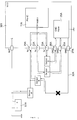
- FIG. 4 and Fig. 5 each depict a configuration example of such a conventional electronic device.
- the conventional device will be described by using the same drawings.
- This conventional device is an example of the electronic device that electrically realizes various types of operation control required for a motor vehicle.
- This electronic device is constructed of a vehicle electronic control unit (described as "ECU” in Fig. 4) 301 as a central component.
- the vehicle electronic control unit 301 has: an IC (not depicted) that has functions such as arithmetic operations and control represented by a microcomputer (not depicted); an interface circuit (not depicted) connected to an external circuit; and the like, and is configured to be able to execute the operation control of an engine and the like on the basis of detection signals acquired by plural sensors, signals from various types of unillustrated switches, and the like.
- This vehicle electronic control unit 301 receives the detection signals from four sensors A to D as the plural sensors, for example.
- the vehicle electronic control unit 301 is provided with a power supply IC (described as "PW-IC" in Fig. 4 and Fig. 5) 11A that converts a battery voltage (for example, 12 V) supplied from a vehicle battery 51A to a prescribed voltage, such as 5 V, required in the electronic circuit and stabilizes and outputs the converted voltage, so as to supply generated 5 V to an unillustrated circuit, the sensors A to D, and the like.
- a power supply IC (described as "PW-IC” in Fig. 4 and Fig. 5) 11A that converts a battery voltage (for example, 12 V) supplied from a vehicle battery 51A to a prescribed voltage, such as 5 V, required in the electronic circuit and stabilizes and outputs the converted voltage, so as to supply generated 5 V to an unillustrated circuit, the sensors A to D, and the like.
- the sensor A requires both of the power supply voltage (for example, 12 V) from the vehicle battery 51A and 5 V from the power supply IC 11A.
- ground for these sensors A to D is collected on a ground plate material 35A that is provided in the vehicle electronic control unit 301, and is connected to a vehicle earth via this ground plate material 35A.
- the ground of the sensors A to D is connected to ground connection terminals 25A to 27A that are provided in the vehicle electronic control unit 301 while being also connected to the vehicle electronic control unit 301, the other external circuit (not depicted), and another electronic control device (not depicted).
- the sufficient number of ground terminals and 5-V power supply terminals are not always provided in the electronic device.
- the sensor C and the sensor D are connected to 5-V power supply terminals 22A, 23A and the ground terminals 25A, 26A that are separately provided in the vehicle electronic control unit 301, the sensor A and the sensor B share a single 5-V power supply terminal 21A and a shared ground terminal 27A, and the sensor A is also supplied with the battery voltage from the vehicle battery 51A.
- a mutual connection point on the ground sides of the sensor A and the sensor B is connected to the shared ground terminal 27A by a shared ground wire 32A (see Fig. 4).
- a shared ground wire 32A is broken for some reason (see a symbol X in Fig. 5), as indicated by two-dot chain lines in Fig. 5, a reverse current flows from the vehicle battery 51A into the 5-V power supply terminal 21A, which is shared by the sensor A and the sensor B, via these sensors A, B. It is because the battery voltage (12 V) is higher than the output voltage of the power supply IC 11A.
- the reverse current flows into the power supply IC 11A via a common 5-V supply wire that is connected to the 5-V power supply terminal 21A shared by the sensors A, B, also flows into the sensors C, D, and eventually reaches the commonly connected vehicle ground from these power supply IC 11A and ground sides of the sensors C, D.
- the circuit disclosed in PTL 1 can protect the load itself, the breakage of which occurs.
- the circuit disclosed in PTL 1 cannot prevent damage, failure, or the like of a component in advance that has a high possibility of secondary damage, failure, or the like occurred thereto, arising from the breakage, that is, the sensors C, D in the electronic device with the configuration that has been described above with reference to Fig. 4 and Fig. 5.
- the invention has been made in view of the above circumstance and therefore provides a secondary failure preventing circuit that can reliably suppress or prevent secondary damage, failure, or the like of an electronic component having a certain power supply voltage, arising from breakage of a common ground wire to electronic components having different power supply voltages.
- an electronic device that includes a secondary failure preventing circuit includes: a dual power-supply type electronic component that requires a first power supply voltage and a second power supply voltage that is lower than the first power supply voltage; a first single power-supply type electronic component that requires the second power supply voltage; at least one wire-unshared single power-supply type electronic component that requires the second power supply voltage; a unit power supply circuit that generates and outputs the second power supply voltage on the basis of the first power supply voltage; and a secondary failure preventing circuit that prevents generation of a reverse current to the wire-unshared single power-supply type electronic component, arising from breakage of a common ground wire to the dual power-supply type electronic component and the first single power-supply type electronic component.
- a secondary preventing circuit blocks application of the second power supply voltage to the dual power-supply type electronic component and the single power-supply type electronic component.
- the generation of the reverse current from the dual power-supply type electronic component side to the other single power-supply type electronic component through a single power-supply type electronic portion, a ground side of which is connected to this dual power-supply type electronic component by the common ground wire is prevented and avoided.
- secondary failure of the other single power-supply type electronic component is reliably prevented or reduced. Therefore, an effect of improving reliability and safety of the entire electronic device is exerted.
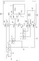
- Fig. 1 depicts a configuration example of an electronic device for vehicle operation control, and the electronic device is constructed of a so-called vehicle electronic control unit 101 as a primary component that executes operation control of a motor vehicle. A description will hereinafter be made on a configuration of the vehicle electronic control unit 101.
- the vehicle electronic control unit 101 has a microcomputer (not depicted) as a central component, a storage device (not depicted), and an interface circuit (not depicted) and is provided with a power supply IC (described as "PW-IC" in Fig. 1) 11 as a unit power supply circuit.
- the power supply IC 11 generates a power supply voltage (a second power supply voltage), such as 5 V, that is required for operations of the microcomputer and the like on the basis of a battery voltage (for example, 12 V) as a first power supply voltage that is supplied from a vehicle battery 51 provided on the outside, and carries out processing such as stabilization of the power supply voltage for output.
- a second power supply voltage such as 5 V
- a battery voltage for example, 12 V
- the vehicle electronic control unit 101 is provided with a battery connection terminal (described as “BAT” in Fig. 1) 20, first to third unit voltage supply terminals 21 to 23, first to third ground connection terminals (described as “GND” in Fig. 1) 25 to 27 and a monitor terminal (described as "MON” in Fig. 1) 28.
- BAT battery connection terminal
- VFD first to third ground connection terminals
- MON monitor terminal
- First to fourth sensors (described as a "Sensor A”, a “Sensor B”, a “Sensor C”, and a “Sensor D” in Fig. 1) 1 to 4 are provided on the outside of this vehicle electronic control unit 101, and detection signals thereof are received by the vehicle electronic control unit 101 and used for the processing such as engine control.
- the second to fourth sensors (single power-supply type electronic components) 2 to 4 are operated by the 5-V power supply voltage while the first sensor (a dual power-supply type electronic component) 1 requires two power supply voltage systems. That is, more specifically, the first sensor 1 requires the two power supply voltages of 12 V and 5 V. Note that an example of such a sensor that requires the two power supply voltage systems is an oxygen sensor in the motor vehicle; however, it is needless to say that the first sensor 1 is not limited thereto.
- the third and fourth sensors 3, 4 as wire-unshared single power-supply type electronic components are provided to be applied with the power supply voltage and connected to the ground without intervening a common wire for the application of the power supply voltage and the connection to the ground.
- the terminals that can be used for the power supply to and the ground connection of the above-described four sensors 1 to 4 are the three unit voltage supply terminals 21 to 23 and the three first to third ground connection terminals 25 to 27, and the number of each type of the terminals is smaller than the number of the sensors by one. For this reason, wiring therebetween is as will be described below.
- a 12-V voltage application side of the first sensor 1 is connected to a positive electrode terminal of the vehicle battery 51 and the battery connection terminal 20 of the vehicle electronic control unit 101.
- Both of a 5-V voltage application side of the first sensor 1 and a 5-V voltage application side of the second sensor (a first single power-supply type electronic component) 2 are connected to the first unit voltage supply terminal 21 of the vehicle electronic control unit 101.
- a 5-V voltage application side of the third sensor 3 and a 5-V voltage application side of the fourth sensor 4 are respectively connected to the second unit voltage supply terminal 22 and the third unit voltage supply terminal 23 of the vehicle electronic control unit 101.
- both of a ground side of the first sensor 1 and a ground side of the second sensor 2 are connected to the third ground connection terminal 27 of the vehicle electronic control unit 101.
- the ground side of the first sensor 1 and the ground side of the second sensor 2 are mutually connected (hereinafter referred to as a "shared ground connection point" for convenience of the description), and a shared ground connection point 31 and the third ground connection terminal 27 are connected by a shared ground wire 32.
- a ground side of the third sensor 3 and a ground side of the fourth sensor 4 are respectively connected to the second ground connection terminal 25 and the first ground connection terminal 26 of the vehicle electronic control unit 101.
- the first unit voltage supply terminal 21 is connected to a first connection terminal 102a of the secondary failure preventing circuit 102.
- the second and third unit voltage supply terminals 22, 23 and a second connection terminal 102b of the secondary failure preventing circuit 102 are mutually connected, and a connection point thereof (hereinafter referred to as a "unit voltage connection point" for convenience of the description) 33 is connected to a voltage output terminal 11a of the power supply IC 11.
- the secondary failure preventing circuit 102 is provided in a manner to be connected in series to a 5-V voltage (second power supply voltage) supply path to the first and second sensors 1, 2.
- each of the first to third ground connection terminals 25 to 27 is connected to a ground connection plate material 35 that is provided in the vehicle electronic control unit 101.
- the ground connection plate material 35 is connected to a specified vehicle earth connection section.
- the secondary failure preventing circuit 102 is a circuit that has a so-called switching function, and is configured to achieve a conductive state between the one connection terminal 102a and the other connection terminal 102b normally, that is, in the case where the shared ground wire 32 is in a state of not being broken but being connected normally and to achieve a non-conductive state between the one connection terminal 102a and the other connection terminal 102b in the case where it is determined that the shared ground wire 32 is broken.
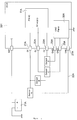
- Such a secondary failure preventing circuit 102 is configured to monitor an electric potential on the ground sides of the first and second sensors 2 in order to determine presence or absence of breakage of the shared ground wire 32, and to achieve the non-conductive state between the one connection terminal 102a and the other connection terminal 102b as described above in the case where the potential exceeds a specified threshold (reference voltage).
- the secondary failure preventing circuit 102 is configured to be able to receive the electric potential on the ground sides of the first and second sensors 1, 2 via the monitor terminal 28.
- the secondary failure preventing circuit 102 in this circuit configuration example is constructed of a comparator 41, a transistor 42, and a relay 43 as primary components.
- an inverting input terminal of the comparator 41 is connected to the monitor terminal 28 and receives the electric potential on the ground sides of the first and second sensors 1, 2.
- a non-inverting input terminal of the comparator 41 receives a divided voltage at a mutual connection point between first and second resistors (respectively described as "R1", “R2” in Fig. 2) 44, 45 as the reference voltage for a comparison operation.
- the first and second resistors 44, 45 are connected in series between a supply line of a secondary circuit power supply voltage Vs and the ground.
- An output terminal of the comparator 41 is connected to a base of the transistor 42 via a third resistor (described as “R3" in Fig. 1) 46, and the base of the transistor 42 is further connected to the ground via a fourth resistor (described as "R4" in Fig. 2) 47.
- a third resistor described as "R3" in Fig. 1
- R4 fourth resistor
- an NPN bipolar transistor is used as the transistor 42.
- the secondary circuit power supply voltage Vs does not have to be limited to a particular voltage value, and any voltage value can be set therefor.
- the secondary circuit power supply voltage Vs may be the battery voltage or 5 V output by the power supply IC 11.
- a collector of the transistor 42 is connected to an end of an electromagnetic coil 43a of the relay 43 as a switching element, and the secondary circuit power supply voltage Vs is applied to the other end of this electromagnetic coil 43a. Meanwhile, an emitter of the transistor 42 is connected to the ground.
- the relay 43 has a normally-closed connection point 43b that is brought into a closed state in a non-excited state where the electromagnetic coil 43a is not excited.
- One end of the normally-closed connection point 43b and the other end of the normally-closed connection point 43b are respectively connected to the first connection terminal 102a and the second connection terminal 102b.
- the comparator 41 outputs a low voltage that corresponds to a logical value Low. Accordingly, the transistor 42 is brought into the non-conductive state, and the electromagnetic coil 43a of the relay 43 is brought into the non-excited state. Thus, the normally-closed connection point 43b is maintained in the closed state. As a result, each of the first unit voltage supply terminal 21 and the second and third unit voltage supply terminals 22, 23 is brought into the conductive state with the voltage output terminal 11a of the power supply IC 11 via the normally-closed connection point 43b, and the voltage is normally supplied thereto by the power supply IC 11.
- the ground sides of the first and second sensors 1, 2 are disconnected from the ground, which brings a state where the battery voltage is applied to the first unit voltage supply terminal 21 via the first and second sensors 1, 2.
- the electric potential on the ground sides of the first and second sensors 1, 2 is increased to be almost equal to the battery voltage.
- the voltage of the non-inverting input terminal of the comparator 41 that is, the electric potential on the ground sides of the first and second sensors 1, 2 that is applied to the non-inverting input terminal via the monitor terminal 28 significantly exceeds the reference voltage of the inverting input terminal, the comparator 41 outputs a voltage that corresponds to a logical value High, and the transistor 42 is brought into the conductive state.
- the electromagnetic coil 43a is excited, the normally-closed connection point 43b is brought into an opened state, and the conductive state of each of the first unit voltage supply terminal 21 and the second and third unit voltage supply terminals 22, 23 with the voltage output terminal 11a of the power supply IC 11 is canceled.
- flow of a reverse current from the vehicle battery 51 via the power supply IC 11 and the third and fourth sensors 3, 4 is reliably avoided, and damage or failure spread to the power supply IC 11 and the third and fourth sensors 3, 4 arising from the breakage of the shared ground wire 32, that is, so-called secondary failure is reliably prevented.
- the NPN bipolar transistor is used as the transistor 42 in the specific circuit example of the secondary failure preventing circuit 102.
- the transistor 42 is not limited thereto, and it is needless to say that a transistor with another structure, such as a MOSFET, can also be used therefor.
- the relay 43 is configured to use the relay 43 to open/close the first and second connection terminals 102a, 102b.
- a configuration of using a so-called semiconductor switch, such as the MOSFET, can also be adopted.
- the second connection terminal 102b of the secondary failure preventing circuit 102 and the second and third unit voltage supply terminals 22, 23 are mutually connected and that the connection point 33 therebetween is connected to the voltage output terminal 11a of the voltage supply IC 11 (see Fig. 1 and Fig. 2).
- the invention is not limited to such a configuration.
- it may be configured that the second connection terminal 102b and the second and third unit voltage supply terminals 22, 23 are separately connected to the voltage output terminal 11a.
- the invention can be applied to an electronic device for which it is desired to reliably prevent or suppress secondary damage, failure, or the like of an electronic component having a certain power supply voltage, arising from breakage of a common ground wire to electronic components having different power supply voltages.
Landscapes
- Physics & Mathematics (AREA)
- General Physics & Mathematics (AREA)
- Engineering & Computer Science (AREA)
- Power Engineering (AREA)
- Chemical & Material Sciences (AREA)
- Combustion & Propulsion (AREA)
- Testing Of Short-Circuits, Discontinuities, Leakage, Or Incorrect Line Connections (AREA)
- Electronic Switches (AREA)
- Valves And Accessory Devices For Braking Systems (AREA)
- Protection Of Static Devices (AREA)
- Emergency Protection Circuit Devices (AREA)
- Direct Current Feeding And Distribution (AREA)
Applications Claiming Priority (2)
| Application Number | Priority Date | Filing Date | Title |
|---|---|---|---|
| JP2015228253 | 2015-11-23 | ||
| PCT/JP2016/081207 WO2017090352A1 (fr) | 2015-11-23 | 2016-10-21 | Dispositif électronique pourvu d'un circuit de prévention de défaillance secondaire |
Publications (2)
| Publication Number | Publication Date |
|---|---|
| EP3382895A1 true EP3382895A1 (fr) | 2018-10-03 |
| EP3382895A4 EP3382895A4 (fr) | 2019-01-09 |
Family
ID=58763705
Family Applications (1)
| Application Number | Title | Priority Date | Filing Date |
|---|---|---|---|
| EP16868301.9A Withdrawn EP3382895A4 (fr) | 2015-11-23 | 2016-10-21 | Dispositif électronique pourvu d'un circuit de prévention de défaillance secondaire |
Country Status (4)
| Country | Link |
|---|---|
| EP (1) | EP3382895A4 (fr) |
| JP (1) | JPWO2017090352A1 (fr) |
| CN (1) | CN108352830A (fr) |
| WO (1) | WO2017090352A1 (fr) |
Cited By (4)
| Publication number | Priority date | Publication date | Assignee | Title |
|---|---|---|---|---|
| FR3090889A1 (fr) * | 2018-12-19 | 2020-06-26 | Psa Automobiles Sa | Dispositif de gestion d’une perte de masse pour un système électrique |
| WO2021122146A1 (fr) * | 2019-12-16 | 2021-06-24 | Knorr-Bremse Systeme für Nutzfahrzeuge GmbH | Système de mesure pour acquérir un paramètre physique et procédé pour faire fonctionner un système de mesure |
| FR3130220A1 (fr) * | 2021-12-09 | 2023-06-16 | Psa Automobiles Sa | Raccordement à la masse distribué d’un dispositif relié à des câbles d’échange de données |
| US11890964B2 (en) | 2021-09-15 | 2024-02-06 | Panasonic Intellectual Property Management Co., Ltd. | Vehicle and control device |
Family Cites Families (11)
| Publication number | Priority date | Publication date | Assignee | Title |
|---|---|---|---|---|
| JPH03166816A (ja) * | 1989-11-27 | 1991-07-18 | Hitachi Ltd | 半導体集積回路装置 |
| DE19931021A1 (de) * | 1999-07-06 | 2001-01-11 | Volkswagen Ag | Schaltungsanordnung zum Schutz vor Verpolungsschäden |
| JP2002159136A (ja) * | 2000-11-17 | 2002-05-31 | Denso Corp | 自動車用制御装置 |
| JP4710739B2 (ja) | 2006-06-30 | 2011-06-29 | 株式会社デンソー | 負荷断線検出回路 |
| JP2008292265A (ja) * | 2007-05-24 | 2008-12-04 | Calsonic Kansei Corp | グランド信号ライン異常検出回路 |
| JP5825957B2 (ja) * | 2011-09-27 | 2015-12-02 | 新電元工業株式会社 | スイッチング回路 |
| JP2013193721A (ja) * | 2012-03-23 | 2013-09-30 | Hitachi Automotive Systems Ltd | 共用電源装置 |
| KR20150089270A (ko) * | 2014-01-27 | 2015-08-05 | 엘에스산전 주식회사 | 배터리 역접속 방지 장치 및 그 동작 방법 |
| JP2016072734A (ja) * | 2014-09-29 | 2016-05-09 | ボッシュ株式会社 | エンジン制御装置および方法 |
| CN104502789B (zh) * | 2015-01-19 | 2017-08-08 | 南车株洲电力机车有限公司 | 一种双源制地铁工程维护车的接地检测电路 |
| CN204651922U (zh) * | 2015-06-02 | 2015-09-16 | 深圳市蓝德汽车电源技术有限公司 | 一种电动汽车电源输入防电流冲击电路 |
-
2016
- 2016-10-21 WO PCT/JP2016/081207 patent/WO2017090352A1/fr unknown
- 2016-10-21 CN CN201680068142.9A patent/CN108352830A/zh active Pending
- 2016-10-21 JP JP2017552317A patent/JPWO2017090352A1/ja active Pending
- 2016-10-21 EP EP16868301.9A patent/EP3382895A4/fr not_active Withdrawn
Cited By (4)
| Publication number | Priority date | Publication date | Assignee | Title |
|---|---|---|---|---|
| FR3090889A1 (fr) * | 2018-12-19 | 2020-06-26 | Psa Automobiles Sa | Dispositif de gestion d’une perte de masse pour un système électrique |
| WO2021122146A1 (fr) * | 2019-12-16 | 2021-06-24 | Knorr-Bremse Systeme für Nutzfahrzeuge GmbH | Système de mesure pour acquérir un paramètre physique et procédé pour faire fonctionner un système de mesure |
| US11890964B2 (en) | 2021-09-15 | 2024-02-06 | Panasonic Intellectual Property Management Co., Ltd. | Vehicle and control device |
| FR3130220A1 (fr) * | 2021-12-09 | 2023-06-16 | Psa Automobiles Sa | Raccordement à la masse distribué d’un dispositif relié à des câbles d’échange de données |
Also Published As
| Publication number | Publication date |
|---|---|
| WO2017090352A1 (fr) | 2017-06-01 |
| CN108352830A (zh) | 2018-07-31 |
| EP3382895A4 (fr) | 2019-01-09 |
| JPWO2017090352A1 (ja) | 2018-07-05 |
Similar Documents
| Publication | Publication Date | Title |
|---|---|---|
| US7504743B2 (en) | Power supply control device for on-vehicle electrical loads | |
| US10139443B2 (en) | Circuit apparatus and method for detecting a state of an interlock loop | |
| EP3382895A1 (fr) | Dispositif électronique pourvu d'un circuit de prévention de défaillance secondaire | |
| CN109477862B (zh) | 车载控制装置 | |
| CN107765073B (zh) | 过电流检测装置、蓄电装置以及电流检测方法 | |
| CN107706882A (zh) | 用于机动车的车载电路系统内的电负载的电子熔断器 | |
| EP3118996B1 (fr) | Circuit d'attaque d'un dispositif de commutation de commande de puissance électrique | |
| US10153632B2 (en) | Device and method for protecting an electrical system component of a vehicle electrical system | |
| US10830830B2 (en) | Battery monitoring device for vehicle-mounted battery | |
| US20200136427A1 (en) | Electronic circuit for redundant supply of an electric load | |
| US10882475B2 (en) | Multi-voltage control device for a motor vehicle, motor vehicle and operating method for the control device | |
| US11435389B2 (en) | Electrical control device detection circuit, detection method, and electric vehicle | |
| CN117426036A (zh) | 车载用断路装置及断路方法 | |
| US10921384B2 (en) | Disconnection sensing circuit and electrical connection box | |
| CN105637762B (zh) | 过电流保护电路 | |
| US9647449B2 (en) | Integrated circuit arrangement, method and system for use in a safety-critical application | |
| CN214669449U (zh) | 接口保护电路、插枪检测电路、电动车辆控制电路和车辆 | |
| US9809120B2 (en) | Discrete under voltage/over voltage monitoring circuit | |
| EP3629040B1 (fr) | Système de détection de câble ouvert et procédé associé | |
| JP6379294B2 (ja) | 電気回路装置 | |
| US11914002B2 (en) | Electrical installation comprising a monitoring module | |
| US20240105411A1 (en) | Status detection circuit and remotely operable switch | |
| US11451045B2 (en) | Automotive auxiliary unit with an electronic protection unit | |
| JP2022169862A (ja) | 保護装置 | |
| CN118414268A (zh) | 电气设备及车载系统 |
Legal Events
| Date | Code | Title | Description |
|---|---|---|---|
| STAA | Information on the status of an ep patent application or granted ep patent |
Free format text: STATUS: THE INTERNATIONAL PUBLICATION HAS BEEN MADE |
|
| PUAI | Public reference made under article 153(3) epc to a published international application that has entered the european phase |
Free format text: ORIGINAL CODE: 0009012 |
|
| STAA | Information on the status of an ep patent application or granted ep patent |
Free format text: STATUS: REQUEST FOR EXAMINATION WAS MADE |
|
| 17P | Request for examination filed |
Effective date: 20180625 |
|
| AK | Designated contracting states |
Kind code of ref document: A1 Designated state(s): AL AT BE BG CH CY CZ DE DK EE ES FI FR GB GR HR HU IE IS IT LI LT LU LV MC MK MT NL NO PL PT RO RS SE SI SK SM TR |
|
| AX | Request for extension of the european patent |
Extension state: BA ME |
|
| A4 | Supplementary search report drawn up and despatched |
Effective date: 20181210 |
|
| RIC1 | Information provided on ipc code assigned before grant |
Ipc: B60R 16/03 20060101ALI20181204BHEP Ipc: G01R 31/02 20060101ALI20181204BHEP Ipc: H02H 3/20 20060101ALI20181204BHEP Ipc: G01R 31/00 20060101ALI20181204BHEP Ipc: H02H 5/10 20060101ALI20181204BHEP Ipc: H03K 17/00 20060101AFI20181204BHEP Ipc: H02H 3/14 20060101ALI20181204BHEP Ipc: B60R 16/02 20060101ALI20181204BHEP Ipc: H02J 1/00 20060101ALI20181204BHEP Ipc: H02J 1/08 20060101ALI20181204BHEP |
|
| DAV | Request for validation of the european patent (deleted) | ||
| DAX | Request for extension of the european patent (deleted) | ||
| STAA | Information on the status of an ep patent application or granted ep patent |
Free format text: STATUS: THE APPLICATION IS DEEMED TO BE WITHDRAWN |
|
| 18D | Application deemed to be withdrawn |
Effective date: 20190718 |