EP3382890B1 - Pumpenanordnung und steuerungsverfahren - Google Patents
Pumpenanordnung und steuerungsverfahren Download PDFInfo
- Publication number
- EP3382890B1 EP3382890B1 EP17164400.8A EP17164400A EP3382890B1 EP 3382890 B1 EP3382890 B1 EP 3382890B1 EP 17164400 A EP17164400 A EP 17164400A EP 3382890 B1 EP3382890 B1 EP 3382890B1
- Authority
- EP
- European Patent Office
- Prior art keywords
- voltage
- input voltage
- power consumption
- converter
- frequency converter
- Prior art date
- Legal status (The legal status is an assumption and is not a legal conclusion. Google has not performed a legal analysis and makes no representation as to the accuracy of the status listed.)
- Active
Links
Images


Classifications
-
- H—ELECTRICITY
- H02—GENERATION; CONVERSION OR DISTRIBUTION OF ELECTRIC POWER
- H02P—CONTROL OR REGULATION OF ELECTRIC MOTORS, ELECTRIC GENERATORS OR DYNAMO-ELECTRIC CONVERTERS; CONTROLLING TRANSFORMERS, REACTORS OR CHOKE COILS
- H02P27/00—Arrangements or methods for the control of AC motors characterised by the kind of supply voltage
- H02P27/04—Arrangements or methods for the control of AC motors characterised by the kind of supply voltage using variable-frequency supply voltage, e.g. inverter or converter supply voltage
- H02P27/047—V/F converter, wherein the voltage is controlled proportionally with the frequency
-
- H—ELECTRICITY
- H02—GENERATION; CONVERSION OR DISTRIBUTION OF ELECTRIC POWER
- H02P—CONTROL OR REGULATION OF ELECTRIC MOTORS, ELECTRIC GENERATORS OR DYNAMO-ELECTRIC CONVERTERS; CONTROLLING TRANSFORMERS, REACTORS OR CHOKE COILS
- H02P27/00—Arrangements or methods for the control of AC motors characterised by the kind of supply voltage
-
- F—MECHANICAL ENGINEERING; LIGHTING; HEATING; WEAPONS; BLASTING
- F04—POSITIVE - DISPLACEMENT MACHINES FOR LIQUIDS; PUMPS FOR LIQUIDS OR ELASTIC FLUIDS
- F04D—NON-POSITIVE-DISPLACEMENT PUMPS
- F04D15/00—Control, e.g. regulation, of pumps, pumping installations or systems
- F04D15/0066—Control, e.g. regulation, of pumps, pumping installations or systems by changing the speed, e.g. of the driving engine
-
- F—MECHANICAL ENGINEERING; LIGHTING; HEATING; WEAPONS; BLASTING
- F04—POSITIVE - DISPLACEMENT MACHINES FOR LIQUIDS; PUMPS FOR LIQUIDS OR ELASTIC FLUIDS
- F04D—NON-POSITIVE-DISPLACEMENT PUMPS
- F04D13/00—Pumping installations or systems
- F04D13/02—Units comprising pumps and their driving means
- F04D13/06—Units comprising pumps and their driving means the pump being electrically driven
- F04D13/0606—Canned motor pumps
-
- H—ELECTRICITY
- H02—GENERATION; CONVERSION OR DISTRIBUTION OF ELECTRIC POWER
- H02P—CONTROL OR REGULATION OF ELECTRIC MOTORS, ELECTRIC GENERATORS OR DYNAMO-ELECTRIC CONVERTERS; CONTROLLING TRANSFORMERS, REACTORS OR CHOKE COILS
- H02P27/00—Arrangements or methods for the control of AC motors characterised by the kind of supply voltage
- H02P27/04—Arrangements or methods for the control of AC motors characterised by the kind of supply voltage using variable-frequency supply voltage, e.g. inverter or converter supply voltage
- H02P27/06—Arrangements or methods for the control of AC motors characterised by the kind of supply voltage using variable-frequency supply voltage, e.g. inverter or converter supply voltage using DC to AC converters or inverters
- H02P27/08—Arrangements or methods for the control of AC motors characterised by the kind of supply voltage using variable-frequency supply voltage, e.g. inverter or converter supply voltage using DC to AC converters or inverters with pulse width modulation
-
- Y—GENERAL TAGGING OF NEW TECHNOLOGICAL DEVELOPMENTS; GENERAL TAGGING OF CROSS-SECTIONAL TECHNOLOGIES SPANNING OVER SEVERAL SECTIONS OF THE IPC; TECHNICAL SUBJECTS COVERED BY FORMER USPC CROSS-REFERENCE ART COLLECTIONS [XRACs] AND DIGESTS
- Y02—TECHNOLOGIES OR APPLICATIONS FOR MITIGATION OR ADAPTATION AGAINST CLIMATE CHANGE
- Y02B—CLIMATE CHANGE MITIGATION TECHNOLOGIES RELATED TO BUILDINGS, e.g. HOUSING, HOUSE APPLIANCES OR RELATED END-USER APPLICATIONS
- Y02B30/00—Energy efficient heating, ventilation or air conditioning [HVAC]
- Y02B30/70—Efficient control or regulation technologies, e.g. for control of refrigerant flow, motor or heating
Definitions
- the present disclosure relates generally to pump assemblies, in particular to speed controlled wet rotor centrifugal pumps, and a method for controlling an electrical drive motor for driving such a pump.
- Such pumps in the power range of 5W to 3kW are typically used in circulation pumps of house heating systems.
- Speed controlled wet rotor pumps usually comprise a frequency converter configured to drive the motor at a desired speed according to the required pumping power.
- the switching frequency of the frequency converter In order to drive the motor with a pulse width modulated signal having a sinusoidal shape, the switching frequency of the frequency converter must be high, which introduces switching losses in the frequency converter.
- EP 2 133 991 describes a speed controlled pump in which the input voltage to the frequency converter is adapted by a voltage converter to the required output voltage aiming for a maximum modulation index for minimising switching losses in the frequency converter.
- embodiments of the present disclosure provide a pump assembly with further reduced power consumption.
- a pump assembly comprising a pump unit, an electrical drive motor for driving the pump unit, and a control unit for controlling the drive motor.
- the control unit comprises a frequency converter, a voltage converter and a controller, wherein the voltage converter is configured to provide an input voltage U in to the frequency converter, the input voltage being adjustable within a voltage range between a minimum input voltage U min and and a maximum output voltage U max .
- the controller is configured to determine an actual power consumption of at least one of the drive motor, the frequency converter and the voltage converter during operation of the pump unit, and configured to tune the input voltage depending on the determined actual power consumption during operation of the pump unit.
- the controller may be part of the frequency converter or of the voltage converter or a separate component of the control unit.
- the controller may be configured to determine an actual combined power consumption of the drive motor, the frequency converter and the voltage converter, and to tune the input voltage depending on the determined actual combined power consumption.
- the controller may be configured to determine an actual combined power consumption of the drive motor, the frequency converter and the voltage converter, and to tune the input voltage depending on the determined actual combined power consumption.
- the controller may thus be configured to tune the input voltage so that the actual power consumption is minimised.
- a minimum power loss (MPL) algorithm may be applied to find the optimal input voltage for achieving the lowest power consumption of the combined system comprising the drive motor, the frequency converter and the voltage converter.
- the MPL algorithm may increase the input voltage from U 0 to U 1 and compares the power consumption P 0 for U 0 and the power consumption P 1 for U 1 . If the power consumption P 1 for U 1 is smaller than the power consumption P 0 for U 0 , the input voltage may be further increased to U 2 .
- the input voltage may be decreased from U 0 to U' 1 , and then further decreased to U' 2 if the power consumption has reduced by ⁇ P from U 0 to U' 1 .
- the controller may be configured to determine a rate of change in actual power consumption in at least one of the drive motor, the frequency converter and the voltage converter during operation of the pump, wherein the controller is configured to tune the input voltage only if the positive rate of change of the actual power consumption is below a defined threshold, or if a parameter relating to the positive rate of change of the actual power consumption is below a defined threshold for that parameter.
- the MPL algorithm may be switched off when the power consumption is rising too quickly and switched on when the power consumption is stable within the defined threshold.
- the controller may be configured to increase the input voltage in a pre-defined manner if the positive rate of change of the actual power consumption is above the threshold. For instance, the input voltage may be increased at a constant rate or steps as long as the positive rate of change of the actual power consumption is above the defined threshold. If the power consumption is rising too quickly, an input voltage achieving a maximum modulation index may be applied.
- the controller may be configured to determine the actual electrical power consumption in pre-defined temporal intervals or in an essentially continuous manner to tune the input voltage accordingly.
- the controller may be configured to determine a power consumption differential ⁇ P between the power consumption when the input voltage is provided and the power consumption when another input voltage was previously provided, wherein tuning the input voltage includes changing the input voltage by a voltage differential ⁇ U, wherein the sign and/or the amount of the voltage differential ⁇ U is dependent on the determined power consumption differential ⁇ P.
- the drive motor may be operable in a field-weakening mode and a non-field-weakening mode, wherein the controller is configured to tune the input voltage within a voltage range between a minimum input voltage U min and a reference voltage U ref in the field weakening mode, and wherein the controller is configured to tune the input voltage within a voltage range between the reference voltage U ref and a maximum input voltage U max in the non-field-weakening mode, wherein U min ⁇ U ref ⁇ U max .
- field-weakening mode shall mean that the stator current partly reduces the total magnetic flux, because it is phase-shifted with respect to the rotor magnetic flux by more than 90°.
- non-field-weakening mode shall mean that a stator current has a phase-shift of 90° or less with respect to the rotor magnetic flux such that no component of the stator current reduces the total magnetic flux.
- the frequency converter and the voltage converter are located on separate circuit boards, preferably separated by a housing wall.
- the pump unit comprises a wet rotor circulation pump for a heating or cooling system.
- a method for controlling an electrical drive motor for driving a pump unit comprising a frequency converter and a voltage converter.
- the method comprises the following steps:
- the step of tuning the input voltage includes tuning the input voltage so that the actual power consumption is minimised.
- the method may comprise a further step of determining a rate of change in actual power consumption in at least one of the drive motor, the frequency converter and the voltage converter during operation of the pump, and wherein tuning the input voltage includes the condition that the positive rate of change of the actual power consumption is below a defined threshold.
- the step of tuning the input voltage includes increasing the input voltage in a pre-defined manner if said condition is not fulfilled.
- the step of determining the actual electrical power consumption includes determining the actual electrical power consumption in pre-defined temporal intervals or in an essentially continuous manner for tuning the input voltage accordingly.
- the step of tuning the input voltage includes tuning the input voltage within a voltage range between the minimum input voltage U min and a reference voltage U ref when the drive motor is operated in a field-weakening mode, and wherein tuning the input voltage includes tuning the input voltage within a voltage range between the reference voltage U ref and the maximum input voltage U max when the drive motor is operated in a non-field-weakening mode, wherein U min ⁇ U ref ⁇ U max .
- the method may comprise a step of feeding back the reference voltage U ref from the frequency converter to the voltage converter.
- the voltage converter may then tune the input voltage to the reference voltage in non-field-weakening mode.
- the method may comprise a step of signalling the determined actual total power consumption to the frequency converter.
- the actual total power consumption may be the actual power consumption of the combined system of frequency converter, motor and voltage converter.
- the step of determining the actual total power consumption includes determining an approximate power consumption in the voltage converter based on a look-up table and/or a determined actual power consumption in the frequency converter and/or the input voltage.
- the method may comprise a step of determining a power consumption differential ⁇ P between the power consumption when the input voltage is provided and the power consumption when another input voltage was previously provided, wherein tuning the input voltage includes changing the input voltage by a voltage differential ⁇ U, wherein the sign and/or the amount of the voltage differential ⁇ U is dependent on the determined power consumption differential ⁇ P.
- Fig. 1 shows a pump assembly 1 with a centrifugal pump unit 2, an input port 3 and an output port 5, wherein the input port 3 and an output port 5 are coaxially arranged on a pipe axis A on opposing sides of the pump unit 2.
- the input port 3 and the output port 5 comprise connector flanges 7, 9 for a connection to pipes (not shown).
- the pump unit 2 comprises a rotor axis R essentially perpendicular to the pipe axis A.
- a pump housing 11 of the pump unit 2 is essentially arranged between the input port 3 and the output port 5.
- the pump housing 11 comprises an impeller (not shown) for rotating around the rotor axis R and pumping fluid from the input port 3 to the output port 5.
- the impeller is driven by a motor (not shown) located in a motor housing 13 extending from the pump housing 11 along the rotor axis R to an electronics housing 15.
- the electronics housing 15 comprises a control unit 201 (see Fig. 2 ) for controlling a three-phase synchronous permanent magnet drive motor 203.
- the control circuitry shown in Fig. 2 comprises the control unit 201 for controlling the three-phase synchronous permanent magnet drive motor 203.
- the control unit 201 receives an AC supply voltage 205.
- This AC supply voltage 205 may be a 230V/110V line voltage or it may be a low AC supply voltage, e.g. 60V, provided by an internal or an external power supply unit (not shown).
- the control unit 201 comprises a voltage converter 207 and a frequency converter 209, wherein the voltage converter 207 receives the AC supply voltage 203 and provides a DC input voltage U in to the frequency converter 209.
- the frequency converter 209 provides to each of the three phases of the drive motor 203 a pulse-width modulated AC output voltage U out for driving the motor 203.
- the three phases are phase-shifted by 120° with respect to each other.
- the control unit 201 further comprises a controller 211 controlling switches within the frequency converter 209.
- the controller 211 may be part of the frequency converter 209 or an extra circuitry.
- the controller 211 comprises a minimum power loss module 213 incorporating a minimum power loss (MPL) algorithm.
- the controller 201 is configured to determine an actual power consumption of at least one of the drive motor 203, the frequency converter 209 and the voltage converter 207, preferably an actual total power consumption of a combined system of motor 203, frequency converter 209 and voltage converter 207, during operation of the pump unit 2.
- the input voltage U in provided by the voltage converter 207 is adjustable within a voltage range between U min and U max , wherein the controller 211 is configured to tune the input voltage U in depending on the determined actual power consumption during operation of the pump unit 2.
- the power loss in the combined system of frequency converter 209 and motor 203 rises in non-field-weakening mode from a reference voltage U ref with the input voltage U in .
- the motor 203 may be operated in field-weakening mode.
- the combined system of frequency converter 209 and motor 203 shows a minimum power loss P loss,FC+M,min (see Fig. 4 ) at an input voltage U in that may differ from the reference voltage U ref .
- a minimum power loss P loss,FC+M,min may be in particular lower than the reference voltage U ref such that it may be advantageous to operate in field-weakening mode.
- the voltage converter 207 is in principle more efficient when outputting higher input voltages U in (see Fig.
- the combined system of frequency converter 209, motor 203 and voltage converter 207 shows a resulting minimum power loss P loss,FC+M+VC,min (see Fig. 8 ) at an input voltage U in that may differ from the reference voltage U ref .
- the controller 211 may be configured to tune the input voltage U in so that the power loss of the combined system of frequency converter 209, motor 203 and voltage converter 207 is at its minimum P loss,FC+M+VC,min as shown in Fig. 8 .
- the vector diagram in a rotating reference frame of Fig. 5 illustrates the phase relation between the main components in non-field weakening mode.
- a magnetic flux ⁇ pm of the permanent magnet is 90° phase-shifted with respect to a phase current I in a stator of the motor 203.
- the resistive voltage drop U R and the back EMF U E are in phase, and the inductive voltage drop U L is 90° phase-shifted with respect to the resistive voltage drop U R .
- the modulation index M is maximal so that the output voltage U out essentially equals a maximum output voltage U out,max illustrated by the circle.
- the input voltage U in may be decreased below the reference voltage U ref , which is possible in field-weakening mode as shown in Fig. 6 .
- the reduced magnetic flux in the motor ⁇ would result in less torque and hydraulic output power of the pump, which may be compensated at part load by a higher phase current I while still consuming less power in total.
- the motor 203 may be operated at full load where the phase current I cannot be increased any further, the field-weakening mode may be less efficient, but that may be rarely the case. Most of the time, the motor 203 may be operated at part load, when a selective operation in field-weakening mode or non-field weakening mode under appropriate tuning of the input voltage U in may be most efficient.
- full load means that the frequency converter is fed with the maximum input power
- part load means that the frequency converter is fed with less than the maximum input power.
- field-weakening mode means that the phase current partly reduces the total magnetic flux, because it is phase-shifted with respect to the rotor magnetic flux by more than 90°.
- the phase current has a phase-shift of 90° or less with respect to the rotor magnetic flux such that no component of the phase current reduces the total magnetic flux.
- position sensors may be used.
- the output voltage U out may be measured to determine whether a motor is running in field-weakening mode or non-field weakening mode.
- the controller 211 is part of the voltage converter 207 receiving the power loss in the frequency converter 209 and in the motor 203 via a feedback loop 215.
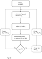
- Fig. 10 further describes the minimum power loss (MPL) algorithm of the minimum power loss (MPL) module 213 of the controller 211.
- MPL minimum power loss
- a first step an initial input voltage U in is provided to the frequency converter 209 by the voltage converter 207.
- the initial input voltage U in is adjustable by an initial voltage differential ⁇ U in so that U in is variably adjustable within a voltage range between U min and U max .
- an actual power consumption P 0 of at least one of the drive motor 203, the frequency converter 209 and the voltage converter 207 during operation of the pump unit 2 is determined and stored.
- the input voltage U in is then varied by the initial voltage differential ⁇ U in , and an actual power consumption P 1 of at least one of the drive motor 203, the frequency converter 209 and the voltage converter 207 during operation of the pump unit 2 is determined.
- the power consumptions P 1 and P 0 are then compared. If P 1 ⁇ P 0 the adjustment decreased the power consumption and the above steps may be repeated starting from the adjusted input voltage U in until P 1 ⁇ P 0 . If P 1 ⁇ P 0 , the sign of ⁇ U in may be changed to adjust U in in the other direction. Thereby, the input voltage U in is tuned depending on the determined actual power consumption during operation of the pump unit 2.
- the MPL algorithm may switch back to the initial voltage differential ⁇ U in once the total minimum power loss of the combined system of frequency converter 209, motor 203 and voltage converter 207 is reached at P loss,FC+M+VC,min .
- the controller 211 may further be configured to determine a rate of change in actual power consumption in at least one of the drive motor 203, the frequency converter 209 and the voltage converter 207 during operation of the pump 1, wherein the controller 211 is configured to tune the input voltage U in only if the positive rate of change of the actual power consumption is below a defined threshold, i.e. the frequency converter 209 is operating in a steady power consumption within limits. If the actual power consumption is rising too quickly above limits, the MPL algorithm of Fig. 10 may be suspended until a steady power consumption within limits is reached. The controller 211 may then increase the input voltage U in in a pre-defined manner, e.g. at a constant rate or steps of ⁇ U in . The controller 211 may determine the actual electrical power consumption in pre-defined temporal intervals or in an essentially continuous manner to start tuning the input voltage U in once the power consumption is stable within limits.
Landscapes
- Engineering & Computer Science (AREA)
- Power Engineering (AREA)
- Mechanical Engineering (AREA)
- General Engineering & Computer Science (AREA)
- Control Of Ac Motors In General (AREA)
Claims (19)
- Pumpenanordnung (1), die Folgendes umfasst- ein Pumpenaggregat (2),- einen elektrischen Antriebsmotor (203) zum Antreiben des Pumpenaggregats (2), und- eine Steuereinheit (201) zum Steuern des Antriebsmotors (203), wobei die Steuereinheit (201) einen Frequenzwandler (209), einen Spannungswandler (207) und einen Controller (211) umfasst,wobei der Spannungswandler (207) konfiguriert ist, um eine Eingangsspannung (Uin) zu dem Frequenzwandler (209) bereitzustellen, wobei die Eingangsspannung (Uin) innerhalb eines Spannungsbereichs zwischen einer Mindesteingangsspannung (Umin) und einer maximalen Eingangsspannung (Umax) einstellbar ist dadurch gekennzeichnet, dass
die Steuervorrichtung (211) konfiguriert ist, um einen tatsächlichen Leistungsverbrauch mindestens eines des Antriebsmotors (203), des Frequenzwandlers (209) und des Spannungswandlers (207) während des Betriebs des Pumpenaggregats (2) zu bestimmen, und
wobei die Steuervorrichtung (211) konfiguriert ist, um die Eingangsspannung (Uin) in Abhängigkeit von dem bestimmten tatsächlichen Leistungsverbrauch während des Betriebs des Pumpenaggregats (2) abzustimmen. - Pumpenanordnung (1) nach Anspruch 1, wobei die Steuervorrichtung (211) konfiguriert ist, um die Eingangsspannung (Uin) derart abzustimmen, dass der tatsächliche Leistungsverbrauch minimiert wird.
- Pumpenanordnung (1) nach einem der vorstehenden Ansprüche, wobei die Steuervorrichtung (211) konfiguriert ist, um eine Änderungsrate des tatsächlichen Leistungsverbrauchs in mindestens einem des Antriebsmotors (203), des Frequenzwandlers (209) und des Spannungswandlers (207) während des Betriebs des Pumpenaggregats (2) zu bestimmen, wobei die Steuervorrichtung (211) konfiguriert ist, um die Eingangsspannung (Uin) nur abzustimmen, falls die positive Änderungsrate des tatsächlichen Leistungsverbrauchs unter einem definierten Schwellenwert liegt.
- Pumpenanordnung (1) nach Anspruch 3, wobei die Steuervorrichtung (211) konfiguriert ist, um die Eingangsspannung (Uin) auf eine vordefinierte Art zu steigern, falls die positive Änderungsrate des tatsächlichen Leistungsverbrauchs über dem Schwellenwert liegt.
- Pumpenanordnung (1) nach einem der vorstehenden Ansprüche, wobei die Steuervorrichtung (211) konfiguriert ist, um den tatsächlichen Stromverbrauch in vordefinierten Zeitintervallen oder auf eine im Wesentlichen kontinuierliche Art zu bestimmen, um die Eingangsspannung (Uin) entsprechend abzustimmen.
- Pumpenanordnung (1) nach einem der vorstehenden Ansprüche, wobei die Steuervorrichtung (211) konfiguriert ist, um ein Leistungsverbrauchsdifferenzial (ΔP) zwischen dem Leistungsverbrauch, wenn die Eingangsspannung (Uin) bereitgestellt wird, und dem Leistungsverbrauch, wenn eine andere Eingangsspannung (Uin) zuvor bereitgestellt wurde, zu bestimmen, wobei das Abstimmen der Eingangsspannung (Uin) das Ändern der Eingangsspannung um ein Spannungsdifferenzial (ΔU) beinhaltet, wobei das Vorzeichen und/oder die Menge an Spannungsdifferenzial (ΔU) von dem bestimmten Leistungsverbrauchsdifferenzial (ΔP) abhängen.
- Pumpenanordnung (1) nach einem der vorstehenden Ansprüche, wobei der Antriebsmotor (203) in einem Feldschwächungsmodus und einem Nicht-Feldschwächungsmodus betreibbar ist, wobei die Steuervorrichtung (211) konfiguriert ist, um die Eingangsspannung (Uin) innerhalb eines Spannungsbereichs zwischen der Mindesteingangsspannung (Umin) und einer Referenzspannung (Uref) in dem Feldschwächungsmodus abzustimmen, und wobei die Steuervorrichtung (211) konfiguriert ist, um die Eingangsspannung (Uin) innerhalb eines Spannungsbereichs zwischen der Referenzspannung (Uref) und der maximalen Eingangsspannung (Umax) in dem Nicht-Feldschwächungsmodus abzustimmen, wobei Umin < Uref < Umax.
- Pumpenanordnung (1) nach einem der vorstehenden Ansprüche, wobei der Frequenzwandler (209) und der Spannungswandler (207) auf separaten Leiterplatten liegen, die vorzugsweise von einer Gehäusewand getrennt sind.
- Pumpenanordnung (1) nach einem der vorstehenden Ansprüche, wobei das Pumpenaggregat (2) eine Nassläuferumwälzpumpe für ein Heiz- oder Kühlsystem umfasst.
- Verfahren zum Steuern eines elektrischen Antriebsmotors (203) zum Antreiben einer Pumpeinheit (2), wobei eine Steuereinheit (211) des elektrischen Antriebsmotors (203) einen Frequenzwandler (209) und einen Spannungswandler (207) umfasst, wobei das Verfahren Folgendes umfasst:- Bereitstellen einer Eingangsspannung (Uin) zu dem Frequenzwandler (209) durch den Spannungswandler (207), wobei die Eingangsspannung (Uin) innerhalb eines Spannungsbereichs zwischen einer Mindesteingangsspannung (Umin) und einer maximalen Eingangsspannung (Umax) einstellbar ist,
gekennzeichnet durch- Bestimmen eines tatsächlichen Leistungsverbrauchs mindestens eines des Antriebsmotors (203), des Frequenzwandlers (209) und des Spannungswandlers (207) während des Betriebs des Pumpenaggregats (2), und- Abstimmen der Eingangsspannung (Uin) in Abhängigkeit von dem bestimmten tatsächlichen Leistungsverbrauch während des Betriebs des Pumpenaggregats (2). - Verfahren nach Anspruch 10, wobei das Abstimmen der Eingangsspannung (Uin) das Abstimmen der Eingangsspannung (Uin) derart beinhaltet, dass der tatsächliche Leistungsverbrauch minimiert wird.
- Verfahren nach Anspruch 10 oder 11, das ferner das Bestimmen einer Änderungsrate des tatsächlichen Leistungsverbrauchs in mindestens einem des Antriebsmotors (203), des Frequenzwandlers (209) und des Spannungswandlers (207) während des Betriebs des Pumpenaggregats (2) umfasst, und wobei das Abstimmen der Eingangsspannung (Uin) die Bedingung umfasst, dass die positive Änderungsrate des tatsächlichen Leistungsverbrauchs unter einem definierten Schwellenwert liegt.
- Verfahren nach Anspruch 12, wobei das Abstimmen der Eingangsspannung (Uin) das Steigern der Eingangsspannung (Uin) auf eine vordefinierte Art beinhaltet, falls die Bedingung nicht erfüllt ist
- Verfahren nach einem der Ansprüche 10 bis 13, wobei das Bestimmen des tatsächlichen Stromverbrauchs das Bestimmen des tatsächlichen Stromverbrauchs in vordefinierten Zeitintervallen oder auf eine im Wesentlichen kontinuierliche Art umfasst, um die Eingangsspannung (Uin) entsprechend abzustimmen.
- Verfahren nach einem der Ansprüche 10 bis 14, wobei das Abstimmen der Eingangsspannung (Uin) das Abstimmen der Eingangsspannung (Uin) innerhalb eines Spannungsbereichs zwischen der Mindesteingangsspannung (Umin) und einer Referenzspannung (Uref), wenn der Antriebsmotor (203) in einem Feldschwächungsmodus betrieben wird, beinhaltet, und wobei das Abstimmen der Eingangsspannung (Uin) das Abstimmen der Eingangsspannung (Uin) innerhalb eines Spannungsbereichs zwischen der Referenzspannung (Uref) und der maximalen Eingangsspannung (Umax), wenn der Antriebsmotor (203) in einem Nicht-Feldschwächungsmodus betrieben wird, beinhaltet, wobei Umin < Uref < Umax.
- Verfahren nach Anspruch 15, das das Zurückspeisen der Referenzspannung (Uref) von dem Frequenzwandler (209) zu dem Spannungswandler (207) umfasst.
- Verfahren nach einem der Ansprüche 10 bis 16, das ferner das Signalisieren eines bestimmten tatsächlichen Gesamtleistungsverbrauchs eines kombinierten Systems aus Frequenzwandler (209), Motor (203) und Spannungswandler (209) zu dem Frequenzwandler (209) umfasst.
- Verfahren nach einem der Ansprüche 10 bis 17, wobei das Bestimmen des tatsächlichen Leistungsverbrauchs eines kombinierten Systems aus Frequenzwandler (209), Motor (203) und Spannungswandler (209) das Bestimmen eines tatsächlichen Gesamtleistungsverbrauchs unter Verwenden eines ungefähren Leistungsverbrauchs in dem Spannungswandler (209) basierend auf einer Nachschlagtabelle und/oder eines bestimmten aktuellen Leistungsverbrauchs in dem Frequenzwandler (209) und/oder der Eingangsspannung (Uin) beinhaltet.
- Verfahren nach einem der Ansprüche 10 bis 18, das weiter das Bestimmen eines Differenzleistungsverbrauchs (ΔP) zwischen dem Leistungsverbrauch, wenn die Eingangsspannung (Uin) bereitgestellt wird, und dem Leistungsverbrauch, wenn eine andere Eingangsspannung (Uin) zuvor bereitgestellt wurde, beinhaltet, wobei das Abstimmen der Eingangsspannung (Uin) das Ändern der Eingangsspannung (Uin) um ein Spannungsdifferenzial (ΔU) umfasst, wobei das Vorzeichen und/oder die Menge des Spannungsdifferenzials (ΔU) von dem bestimmten Leistungsverbrauchsdifferenzial (ΔP) abhängen.
Priority Applications (4)
| Application Number | Priority Date | Filing Date | Title |
|---|---|---|---|
| EP17164400.8A EP3382890B2 (de) | 2017-03-31 | 2017-03-31 | Pumpenanordnung und steuerungsverfahren |
| US15/938,302 US10361649B2 (en) | 2017-03-31 | 2018-03-28 | Pump assembly and controlling method |
| RU2018111032A RU2696723C1 (ru) | 2017-03-31 | 2018-03-28 | Насосный узел и способ управления |
| CN201810282017.9A CN108696227B (zh) | 2017-03-31 | 2018-04-02 | 泵组件及控制方法 |
Applications Claiming Priority (1)
| Application Number | Priority Date | Filing Date | Title |
|---|---|---|---|
| EP17164400.8A EP3382890B2 (de) | 2017-03-31 | 2017-03-31 | Pumpenanordnung und steuerungsverfahren |
Publications (3)
| Publication Number | Publication Date |
|---|---|
| EP3382890A1 EP3382890A1 (de) | 2018-10-03 |
| EP3382890B1 true EP3382890B1 (de) | 2020-07-22 |
| EP3382890B2 EP3382890B2 (de) | 2023-05-24 |
Family
ID=58489521
Family Applications (1)
| Application Number | Title | Priority Date | Filing Date |
|---|---|---|---|
| EP17164400.8A Active EP3382890B2 (de) | 2017-03-31 | 2017-03-31 | Pumpenanordnung und steuerungsverfahren |
Country Status (4)
| Country | Link |
|---|---|
| US (1) | US10361649B2 (de) |
| EP (1) | EP3382890B2 (de) |
| CN (1) | CN108696227B (de) |
| RU (1) | RU2696723C1 (de) |
Families Citing this family (1)
| Publication number | Priority date | Publication date | Assignee | Title |
|---|---|---|---|---|
| US11286925B2 (en) * | 2019-04-23 | 2022-03-29 | Peopleflo Manufacturing, Inc. | Electronic apparatus and method for optimizing the use of motor-driven equipment in a control loop system |
Citations (6)
| Publication number | Priority date | Publication date | Assignee | Title |
|---|---|---|---|---|
| US4249120A (en) | 1979-07-26 | 1981-02-03 | Mcgraw-Edison Co. | Variable speed induction motor control system |
| EP1286458A1 (de) | 2001-08-22 | 2003-02-26 | Pumpenfabrik Ernst Vogel Gesellschaft m.b.H. | Verfahren und Vorrichtung zur Regelung von Kreiselarbeitsmaschinen |
| US20050068001A1 (en) | 2001-11-23 | 2005-03-31 | Danfoss Drives A/S | Frequency converter for different mains voltages |
| EP2133991B1 (de) | 2008-06-09 | 2011-06-08 | Grundfos Management A/S | Kreiselpumpenaggregat |
| US20140136000A1 (en) | 2012-11-15 | 2014-05-15 | Abb Oy | Method for approximating a static head of a fluid transfer system |
| US20150326093A1 (en) | 2012-12-27 | 2015-11-12 | Grundfos Holding A/S | Pump unit |
Family Cites Families (10)
| Publication number | Priority date | Publication date | Assignee | Title |
|---|---|---|---|---|
| US4473338A (en) * | 1980-09-15 | 1984-09-25 | Garmong Victor H | Controlled well pump and method of analyzing well production |
| US5092302A (en) * | 1990-12-26 | 1992-03-03 | Ford Motor Company | Fuel pump speed control by dc-dc converter |
| US5318409A (en) * | 1993-03-23 | 1994-06-07 | Westinghouse Electric Corp. | Rod pump flow rate determination from motor power |
| US6045333A (en) * | 1997-12-01 | 2000-04-04 | Camco International, Inc. | Method and apparatus for controlling a submergible pumping system |
| RU2157468C1 (ru) * | 1999-02-08 | 2000-10-10 | Самарская государственная архитектурно-строительная академия | Способ регулирования расхода центробежного электронасоса |
| US6414455B1 (en) * | 2000-04-03 | 2002-07-02 | Alvin J. Watson | System and method for variable drive pump control |
| TWI495256B (zh) * | 2012-06-26 | 2015-08-01 | Asia Pacific Fuel Cell Tech | 馬達電源控制系統 |
| EP2905888A1 (de) * | 2014-02-05 | 2015-08-12 | Grundfos Holding A/S | Stromrichter |
| JP6345135B2 (ja) * | 2015-02-25 | 2018-06-20 | 東芝キヤリア株式会社 | モータ駆動装置 |
| CN106026851A (zh) * | 2016-07-13 | 2016-10-12 | 广州东芝白云菱机电力电子有限公司 | 基于斩波器作电源补偿的电机变频器 |
-
2017
- 2017-03-31 EP EP17164400.8A patent/EP3382890B2/de active Active
-
2018
- 2018-03-28 US US15/938,302 patent/US10361649B2/en active Active
- 2018-03-28 RU RU2018111032A patent/RU2696723C1/ru active
- 2018-04-02 CN CN201810282017.9A patent/CN108696227B/zh active Active
Patent Citations (6)
| Publication number | Priority date | Publication date | Assignee | Title |
|---|---|---|---|---|
| US4249120A (en) | 1979-07-26 | 1981-02-03 | Mcgraw-Edison Co. | Variable speed induction motor control system |
| EP1286458A1 (de) | 2001-08-22 | 2003-02-26 | Pumpenfabrik Ernst Vogel Gesellschaft m.b.H. | Verfahren und Vorrichtung zur Regelung von Kreiselarbeitsmaschinen |
| US20050068001A1 (en) | 2001-11-23 | 2005-03-31 | Danfoss Drives A/S | Frequency converter for different mains voltages |
| EP2133991B1 (de) | 2008-06-09 | 2011-06-08 | Grundfos Management A/S | Kreiselpumpenaggregat |
| US20140136000A1 (en) | 2012-11-15 | 2014-05-15 | Abb Oy | Method for approximating a static head of a fluid transfer system |
| US20150326093A1 (en) | 2012-12-27 | 2015-11-12 | Grundfos Holding A/S | Pump unit |
Non-Patent Citations (2)
| Title |
|---|
| POHLENZ DANIEL, ET AL.: "Wirkungsgradoptimale Regelung eines elektrischen Fahrantriebes mit variabler Zwischenkreisspannung", DISSERTATION UNIVERSITY OF PADERBORN, HISTORISCH CENTRUM LIMBURG, 1 January 2012 (2012-01-01), XP055960935, [retrieved on 20220914] |
| TIMO SCHOENEN ; MARKUS S. KUNTER ; MARTIN D. HENNEN ; RIK W. DE DONCKER: "Advantages of a variable DC-link voltage by using a DC-DC converter in hybrid-electric vehicles", VEHICLE POWER AND PROPULSION CONFERENCE (VPPC), 2010 IEEE, IEEE, 1 September 2010 (2010-09-01), pages 1 - 5, XP031929139, ISBN: 978-1-4244-8220-7, DOI: 10.1109/VPPC.2010.5729003 |
Also Published As
| Publication number | Publication date |
|---|---|
| US20180287542A1 (en) | 2018-10-04 |
| CN108696227A (zh) | 2018-10-23 |
| US10361649B2 (en) | 2019-07-23 |
| EP3382890A1 (de) | 2018-10-03 |
| EP3382890B2 (de) | 2023-05-24 |
| CN108696227B (zh) | 2021-10-08 |
| RU2696723C1 (ru) | 2019-08-05 |
Similar Documents
| Publication | Publication Date | Title |
|---|---|---|
| CN101884164B (zh) | 交流电动机的控制装置 | |
| EP2465195B1 (de) | Steuerung und verfahren für den übergang zwischen steuerwinkeln | |
| US8228016B2 (en) | Gain adjustment to improve torque linearity in a field weakening region | |
| US6222335B1 (en) | Method of controlling a voltage-fed induction machine | |
| CN105324932B (zh) | 驱动装置 | |
| EP2151918A1 (de) | Betreiben eines Synchronmotors mit einem Permanentmagnetrotor | |
| US20090309525A1 (en) | Drive for motor | |
| US10756664B2 (en) | System for applying maximum driving efficiency point of load | |
| US6979967B2 (en) | Efficiency optimization control for permanent magnet motor drive | |
| EP3482491B1 (de) | Flussabschwächung mit geschlossenem regelkreis für permanentmagent-synchronmotoren | |
| JP3806539B2 (ja) | 永久磁石式同期モータの制御方法 | |
| EP3382890B1 (de) | Pumpenanordnung und steuerungsverfahren | |
| JP2006149097A (ja) | モータ制御装置 | |
| EP3382888B1 (de) | Pumpenanordnung und steuerungsverfahren | |
| US11005394B2 (en) | Control system and control method | |
| JP2018042315A (ja) | インバータ制御装置 | |
| JP2005229736A (ja) | 電動機駆動装置およびそれを用いた空気調和機 | |
| JP4791319B2 (ja) | インバータ装置、圧縮機駆動装置および冷凍・空調装置 | |
| JP2004266904A (ja) | モータの運転制御装置 | |
| US12451829B2 (en) | Variable frequency drive synchronous reluctance motor system with volts-per-Hertz control | |
| US12176837B2 (en) | Motor flying start using field weakening control | |
| JP2021013290A (ja) | モータ制御装置 | |
| JP3662146B2 (ja) | ブラシレスモータ駆動回路及びブラシレスモータ駆動回路の制御方法 | |
| EP3872982A1 (de) | Steuereinheit und steuerverfahren zur steuerung eines motors | |
| KR101731015B1 (ko) | 영구자석 동기 전동기 및 전동기 제어 시스템 |
Legal Events
| Date | Code | Title | Description |
|---|---|---|---|
| PUAI | Public reference made under article 153(3) epc to a published international application that has entered the european phase |
Free format text: ORIGINAL CODE: 0009012 |
|
| STAA | Information on the status of an ep patent application or granted ep patent |
Free format text: STATUS: THE APPLICATION HAS BEEN PUBLISHED |
|
| AK | Designated contracting states |
Kind code of ref document: A1 Designated state(s): AL AT BE BG CH CY CZ DE DK EE ES FI FR GB GR HR HU IE IS IT LI LT LU LV MC MK MT NL NO PL PT RO RS SE SI SK SM TR |
|
| AX | Request for extension of the european patent |
Extension state: BA ME |
|
| STAA | Information on the status of an ep patent application or granted ep patent |
Free format text: STATUS: REQUEST FOR EXAMINATION WAS MADE |
|
| 17P | Request for examination filed |
Effective date: 20190129 |
|
| RBV | Designated contracting states (corrected) |
Designated state(s): AL AT BE BG CH CY CZ DE DK EE ES FI FR GB GR HR HU IE IS IT LI LT LU LV MC MK MT NL NO PL PT RO RS SE SI SK SM TR |
|
| GRAP | Despatch of communication of intention to grant a patent |
Free format text: ORIGINAL CODE: EPIDOSNIGR1 |
|
| STAA | Information on the status of an ep patent application or granted ep patent |
Free format text: STATUS: GRANT OF PATENT IS INTENDED |
|
| INTG | Intention to grant announced |
Effective date: 20200218 |
|
| GRAS | Grant fee paid |
Free format text: ORIGINAL CODE: EPIDOSNIGR3 |
|
| GRAA | (expected) grant |
Free format text: ORIGINAL CODE: 0009210 |
|
| STAA | Information on the status of an ep patent application or granted ep patent |
Free format text: STATUS: THE PATENT HAS BEEN GRANTED |
|
| AK | Designated contracting states |
Kind code of ref document: B1 Designated state(s): AL AT BE BG CH CY CZ DE DK EE ES FI FR GB GR HR HU IE IS IT LI LT LU LV MC MK MT NL NO PL PT RO RS SE SI SK SM TR |
|
| REG | Reference to a national code |
Ref country code: GB Ref legal event code: FG4D |
|
| REG | Reference to a national code |
Ref country code: CH Ref legal event code: EP |
|
| REG | Reference to a national code |
Ref country code: DE Ref legal event code: R096 Ref document number: 602017020037 Country of ref document: DE |
|
| REG | Reference to a national code |
Ref country code: AT Ref legal event code: REF Ref document number: 1294341 Country of ref document: AT Kind code of ref document: T Effective date: 20200815 |
|
| REG | Reference to a national code |
Ref country code: IE Ref legal event code: FG4D |
|
| REG | Reference to a national code |
Ref country code: LT Ref legal event code: MG4D |
|
| REG | Reference to a national code |
Ref country code: AT Ref legal event code: MK05 Ref document number: 1294341 Country of ref document: AT Kind code of ref document: T Effective date: 20200722 |
|
| PG25 | Lapsed in a contracting state [announced via postgrant information from national office to epo] |
Ref country code: FI Free format text: LAPSE BECAUSE OF FAILURE TO SUBMIT A TRANSLATION OF THE DESCRIPTION OR TO PAY THE FEE WITHIN THE PRESCRIBED TIME-LIMIT Effective date: 20200722 Ref country code: LT Free format text: LAPSE BECAUSE OF FAILURE TO SUBMIT A TRANSLATION OF THE DESCRIPTION OR TO PAY THE FEE WITHIN THE PRESCRIBED TIME-LIMIT Effective date: 20200722 Ref country code: PT Free format text: LAPSE BECAUSE OF FAILURE TO SUBMIT A TRANSLATION OF THE DESCRIPTION OR TO PAY THE FEE WITHIN THE PRESCRIBED TIME-LIMIT Effective date: 20201123 Ref country code: BG Free format text: LAPSE BECAUSE OF FAILURE TO SUBMIT A TRANSLATION OF THE DESCRIPTION OR TO PAY THE FEE WITHIN THE PRESCRIBED TIME-LIMIT Effective date: 20201022 Ref country code: AT Free format text: LAPSE BECAUSE OF FAILURE TO SUBMIT A TRANSLATION OF THE DESCRIPTION OR TO PAY THE FEE WITHIN THE PRESCRIBED TIME-LIMIT Effective date: 20200722 Ref country code: ES Free format text: LAPSE BECAUSE OF FAILURE TO SUBMIT A TRANSLATION OF THE DESCRIPTION OR TO PAY THE FEE WITHIN THE PRESCRIBED TIME-LIMIT Effective date: 20200722 Ref country code: NO Free format text: LAPSE BECAUSE OF FAILURE TO SUBMIT A TRANSLATION OF THE DESCRIPTION OR TO PAY THE FEE WITHIN THE PRESCRIBED TIME-LIMIT Effective date: 20201022 Ref country code: GR Free format text: LAPSE BECAUSE OF FAILURE TO SUBMIT A TRANSLATION OF THE DESCRIPTION OR TO PAY THE FEE WITHIN THE PRESCRIBED TIME-LIMIT Effective date: 20201023 Ref country code: HR Free format text: LAPSE BECAUSE OF FAILURE TO SUBMIT A TRANSLATION OF THE DESCRIPTION OR TO PAY THE FEE WITHIN THE PRESCRIBED TIME-LIMIT Effective date: 20200722 Ref country code: SE Free format text: LAPSE BECAUSE OF FAILURE TO SUBMIT A TRANSLATION OF THE DESCRIPTION OR TO PAY THE FEE WITHIN THE PRESCRIBED TIME-LIMIT Effective date: 20200722 |
|
| PG25 | Lapsed in a contracting state [announced via postgrant information from national office to epo] |
Ref country code: RS Free format text: LAPSE BECAUSE OF FAILURE TO SUBMIT A TRANSLATION OF THE DESCRIPTION OR TO PAY THE FEE WITHIN THE PRESCRIBED TIME-LIMIT Effective date: 20200722 Ref country code: PL Free format text: LAPSE BECAUSE OF FAILURE TO SUBMIT A TRANSLATION OF THE DESCRIPTION OR TO PAY THE FEE WITHIN THE PRESCRIBED TIME-LIMIT Effective date: 20200722 Ref country code: LV Free format text: LAPSE BECAUSE OF FAILURE TO SUBMIT A TRANSLATION OF THE DESCRIPTION OR TO PAY THE FEE WITHIN THE PRESCRIBED TIME-LIMIT Effective date: 20200722 Ref country code: IS Free format text: LAPSE BECAUSE OF FAILURE TO SUBMIT A TRANSLATION OF THE DESCRIPTION OR TO PAY THE FEE WITHIN THE PRESCRIBED TIME-LIMIT Effective date: 20201122 |
|
| PG25 | Lapsed in a contracting state [announced via postgrant information from national office to epo] |
Ref country code: NL Free format text: LAPSE BECAUSE OF FAILURE TO SUBMIT A TRANSLATION OF THE DESCRIPTION OR TO PAY THE FEE WITHIN THE PRESCRIBED TIME-LIMIT Effective date: 20200722 |
|
| REG | Reference to a national code |
Ref country code: DE Ref legal event code: R026 Ref document number: 602017020037 Country of ref document: DE |
|
| PG25 | Lapsed in a contracting state [announced via postgrant information from national office to epo] |
Ref country code: EE Free format text: LAPSE BECAUSE OF FAILURE TO SUBMIT A TRANSLATION OF THE DESCRIPTION OR TO PAY THE FEE WITHIN THE PRESCRIBED TIME-LIMIT Effective date: 20200722 Ref country code: SM Free format text: LAPSE BECAUSE OF FAILURE TO SUBMIT A TRANSLATION OF THE DESCRIPTION OR TO PAY THE FEE WITHIN THE PRESCRIBED TIME-LIMIT Effective date: 20200722 Ref country code: RO Free format text: LAPSE BECAUSE OF FAILURE TO SUBMIT A TRANSLATION OF THE DESCRIPTION OR TO PAY THE FEE WITHIN THE PRESCRIBED TIME-LIMIT Effective date: 20200722 Ref country code: CZ Free format text: LAPSE BECAUSE OF FAILURE TO SUBMIT A TRANSLATION OF THE DESCRIPTION OR TO PAY THE FEE WITHIN THE PRESCRIBED TIME-LIMIT Effective date: 20200722 Ref country code: DK Free format text: LAPSE BECAUSE OF FAILURE TO SUBMIT A TRANSLATION OF THE DESCRIPTION OR TO PAY THE FEE WITHIN THE PRESCRIBED TIME-LIMIT Effective date: 20200722 |
|
| PLBI | Opposition filed |
Free format text: ORIGINAL CODE: 0009260 |
|
| PLAX | Notice of opposition and request to file observation + time limit sent |
Free format text: ORIGINAL CODE: EPIDOSNOBS2 |
|
| PG25 | Lapsed in a contracting state [announced via postgrant information from national office to epo] |
Ref country code: AL Free format text: LAPSE BECAUSE OF FAILURE TO SUBMIT A TRANSLATION OF THE DESCRIPTION OR TO PAY THE FEE WITHIN THE PRESCRIBED TIME-LIMIT Effective date: 20200722 |
|
| 26 | Opposition filed |
Opponent name: KSB SE & CO. KGAA Effective date: 20210422 Opponent name: WILO SE Effective date: 20210422 |
|
| PG25 | Lapsed in a contracting state [announced via postgrant information from national office to epo] |
Ref country code: SK Free format text: LAPSE BECAUSE OF FAILURE TO SUBMIT A TRANSLATION OF THE DESCRIPTION OR TO PAY THE FEE WITHIN THE PRESCRIBED TIME-LIMIT Effective date: 20200722 |
|
| PG25 | Lapsed in a contracting state [announced via postgrant information from national office to epo] |
Ref country code: SI Free format text: LAPSE BECAUSE OF FAILURE TO SUBMIT A TRANSLATION OF THE DESCRIPTION OR TO PAY THE FEE WITHIN THE PRESCRIBED TIME-LIMIT Effective date: 20200722 |
|
| PLBB | Reply of patent proprietor to notice(s) of opposition received |
Free format text: ORIGINAL CODE: EPIDOSNOBS3 |
|
| REG | Reference to a national code |
Ref country code: NL Ref legal event code: MP Effective date: 20200722 |
|
| PG25 | Lapsed in a contracting state [announced via postgrant information from national office to epo] |
Ref country code: MC Free format text: LAPSE BECAUSE OF FAILURE TO SUBMIT A TRANSLATION OF THE DESCRIPTION OR TO PAY THE FEE WITHIN THE PRESCRIBED TIME-LIMIT Effective date: 20200722 |
|
| REG | Reference to a national code |
Ref country code: CH Ref legal event code: PL |
|
| REG | Reference to a national code |
Ref country code: BE Ref legal event code: MM Effective date: 20210331 |
|
| PG25 | Lapsed in a contracting state [announced via postgrant information from national office to epo] |
Ref country code: LI Free format text: LAPSE BECAUSE OF NON-PAYMENT OF DUE FEES Effective date: 20210331 Ref country code: LU Free format text: LAPSE BECAUSE OF NON-PAYMENT OF DUE FEES Effective date: 20210331 Ref country code: CH Free format text: LAPSE BECAUSE OF NON-PAYMENT OF DUE FEES Effective date: 20210331 Ref country code: IE Free format text: LAPSE BECAUSE OF NON-PAYMENT OF DUE FEES Effective date: 20210331 |
|
| PG25 | Lapsed in a contracting state [announced via postgrant information from national office to epo] |
Ref country code: BE Free format text: LAPSE BECAUSE OF NON-PAYMENT OF DUE FEES Effective date: 20210331 |
|
| REG | Reference to a national code |
Ref country code: DE Ref legal event code: R082 Ref document number: 602017020037 Country of ref document: DE |
|
| PUAH | Patent maintained in amended form |
Free format text: ORIGINAL CODE: 0009272 |
|
| STAA | Information on the status of an ep patent application or granted ep patent |
Free format text: STATUS: PATENT MAINTAINED AS AMENDED |
|
| 27A | Patent maintained in amended form |
Effective date: 20230524 |
|
| AK | Designated contracting states |
Kind code of ref document: B2 Designated state(s): AL AT BE BG CH CY CZ DE DK EE ES FI FR GB GR HR HU IE IS IT LI LT LU LV MC MK MT NL NO PL PT RO RS SE SI SK SM TR |
|
| REG | Reference to a national code |
Ref country code: DE Ref legal event code: R102 Ref document number: 602017020037 Country of ref document: DE |
|
| PG25 | Lapsed in a contracting state [announced via postgrant information from national office to epo] |
Ref country code: CY Free format text: LAPSE BECAUSE OF FAILURE TO SUBMIT A TRANSLATION OF THE DESCRIPTION OR TO PAY THE FEE WITHIN THE PRESCRIBED TIME-LIMIT Effective date: 20200722 |
|
| PG25 | Lapsed in a contracting state [announced via postgrant information from national office to epo] |
Ref country code: HU Free format text: LAPSE BECAUSE OF FAILURE TO SUBMIT A TRANSLATION OF THE DESCRIPTION OR TO PAY THE FEE WITHIN THE PRESCRIBED TIME-LIMIT; INVALID AB INITIO Effective date: 20170331 |
|
| PG25 | Lapsed in a contracting state [announced via postgrant information from national office to epo] |
Ref country code: MK Free format text: LAPSE BECAUSE OF FAILURE TO SUBMIT A TRANSLATION OF THE DESCRIPTION OR TO PAY THE FEE WITHIN THE PRESCRIBED TIME-LIMIT Effective date: 20200722 |
|
| PG25 | Lapsed in a contracting state [announced via postgrant information from national office to epo] |
Ref country code: MT Free format text: LAPSE BECAUSE OF FAILURE TO SUBMIT A TRANSLATION OF THE DESCRIPTION OR TO PAY THE FEE WITHIN THE PRESCRIBED TIME-LIMIT Effective date: 20200722 |
|
| PG25 | Lapsed in a contracting state [announced via postgrant information from national office to epo] |
Ref country code: TR Free format text: LAPSE BECAUSE OF FAILURE TO SUBMIT A TRANSLATION OF THE DESCRIPTION OR TO PAY THE FEE WITHIN THE PRESCRIBED TIME-LIMIT Effective date: 20200722 |
|
| PGFP | Annual fee paid to national office [announced via postgrant information from national office to epo] |
Ref country code: GB Payment date: 20260324 Year of fee payment: 10 |
|
| PGFP | Annual fee paid to national office [announced via postgrant information from national office to epo] |
Ref country code: DE Payment date: 20260319 Year of fee payment: 10 |
|
| PGFP | Annual fee paid to national office [announced via postgrant information from national office to epo] |
Ref country code: IT Payment date: 20260324 Year of fee payment: 10 |
|
| PGFP | Annual fee paid to national office [announced via postgrant information from national office to epo] |
Ref country code: FR Payment date: 20260320 Year of fee payment: 10 |