EP3382877A1 - Electronic control device and electric power steering device equipped therewith - Google Patents
Electronic control device and electric power steering device equipped therewith Download PDFInfo
- Publication number
- EP3382877A1 EP3382877A1 EP16868555.0A EP16868555A EP3382877A1 EP 3382877 A1 EP3382877 A1 EP 3382877A1 EP 16868555 A EP16868555 A EP 16868555A EP 3382877 A1 EP3382877 A1 EP 3382877A1
- Authority
- EP
- European Patent Office
- Prior art keywords
- mcu
- external wdt
- inverter
- control unit
- electronic control
- Prior art date
- Legal status (The legal status is an assumption and is not a legal conclusion. Google has not performed a legal analysis and makes no representation as to the accuracy of the status listed.)
- Granted
Links
- 230000005856 abnormality Effects 0.000 claims abstract description 30
- 239000004065 semiconductor Substances 0.000 claims abstract description 14
- 238000004891 communication Methods 0.000 claims description 4
- 230000005669 field effect Effects 0.000 claims description 3
- 230000002093 peripheral effect Effects 0.000 claims description 3
- 230000006870 function Effects 0.000 description 23
- 230000002159 abnormal effect Effects 0.000 description 6
- 238000010586 diagram Methods 0.000 description 6
- 230000000694 effects Effects 0.000 description 5
- 101100119059 Saccharomyces cerevisiae (strain ATCC 204508 / S288c) ERG25 gene Proteins 0.000 description 2
- 238000001514 detection method Methods 0.000 description 2
- 230000003071 parasitic effect Effects 0.000 description 2
- 230000005540 biological transmission Effects 0.000 description 1
- 230000008571 general function Effects 0.000 description 1
- 238000000034 method Methods 0.000 description 1
- 230000001360 synchronised effect Effects 0.000 description 1
Images


Classifications
-
- B—PERFORMING OPERATIONS; TRANSPORTING
- B62—LAND VEHICLES FOR TRAVELLING OTHERWISE THAN ON RAILS
- B62D—MOTOR VEHICLES; TRAILERS
- B62D5/00—Power-assisted or power-driven steering
- B62D5/04—Power-assisted or power-driven steering electrical, e.g. using an electric servo-motor connected to, or forming part of, the steering gear
- B62D5/0457—Power-assisted or power-driven steering electrical, e.g. using an electric servo-motor connected to, or forming part of, the steering gear characterised by control features of the drive means as such
- B62D5/046—Controlling the motor
- B62D5/0463—Controlling the motor calculating assisting torque from the motor based on driver input
-
- B—PERFORMING OPERATIONS; TRANSPORTING
- B62—LAND VEHICLES FOR TRAVELLING OTHERWISE THAN ON RAILS
- B62D—MOTOR VEHICLES; TRAILERS
- B62D5/00—Power-assisted or power-driven steering
- B62D5/04—Power-assisted or power-driven steering electrical, e.g. using an electric servo-motor connected to, or forming part of, the steering gear
- B62D5/0421—Electric motor acting on or near steering gear
-
- B—PERFORMING OPERATIONS; TRANSPORTING
- B62—LAND VEHICLES FOR TRAVELLING OTHERWISE THAN ON RAILS
- B62D—MOTOR VEHICLES; TRAILERS
- B62D5/00—Power-assisted or power-driven steering
- B62D5/04—Power-assisted or power-driven steering electrical, e.g. using an electric servo-motor connected to, or forming part of, the steering gear
- B62D5/0457—Power-assisted or power-driven steering electrical, e.g. using an electric servo-motor connected to, or forming part of, the steering gear characterised by control features of the drive means as such
- B62D5/0481—Power-assisted or power-driven steering electrical, e.g. using an electric servo-motor connected to, or forming part of, the steering gear characterised by control features of the drive means as such monitoring the steering system, e.g. failures
- B62D5/0493—Power-assisted or power-driven steering electrical, e.g. using an electric servo-motor connected to, or forming part of, the steering gear characterised by control features of the drive means as such monitoring the steering system, e.g. failures detecting processor errors, e.g. plausibility of steering direction
-
- B—PERFORMING OPERATIONS; TRANSPORTING
- B62—LAND VEHICLES FOR TRAVELLING OTHERWISE THAN ON RAILS
- B62D—MOTOR VEHICLES; TRAILERS
- B62D6/00—Arrangements for automatically controlling steering depending on driving conditions sensed and responded to, e.g. control circuits
-
- G—PHYSICS
- G05—CONTROLLING; REGULATING
- G05B—CONTROL OR REGULATING SYSTEMS IN GENERAL; FUNCTIONAL ELEMENTS OF SUCH SYSTEMS; MONITORING OR TESTING ARRANGEMENTS FOR SUCH SYSTEMS OR ELEMENTS
- G05B19/00—Programme-control systems
- G05B19/02—Programme-control systems electric
- G05B19/04—Programme control other than numerical control, i.e. in sequence controllers or logic controllers
- G05B19/042—Programme control other than numerical control, i.e. in sequence controllers or logic controllers using digital processors
- G05B19/0428—Safety, monitoring
-
- G—PHYSICS
- G06—COMPUTING; CALCULATING OR COUNTING
- G06F—ELECTRIC DIGITAL DATA PROCESSING
- G06F11/00—Error detection; Error correction; Monitoring
- G06F11/07—Responding to the occurrence of a fault, e.g. fault tolerance
- G06F11/0703—Error or fault processing not based on redundancy, i.e. by taking additional measures to deal with the error or fault not making use of redundancy in operation, in hardware, or in data representation
- G06F11/0706—Error or fault processing not based on redundancy, i.e. by taking additional measures to deal with the error or fault not making use of redundancy in operation, in hardware, or in data representation the processing taking place on a specific hardware platform or in a specific software environment
- G06F11/0736—Error or fault processing not based on redundancy, i.e. by taking additional measures to deal with the error or fault not making use of redundancy in operation, in hardware, or in data representation the processing taking place on a specific hardware platform or in a specific software environment in functional embedded systems, i.e. in a data processing system designed as a combination of hardware and software dedicated to performing a certain function
- G06F11/0739—Error or fault processing not based on redundancy, i.e. by taking additional measures to deal with the error or fault not making use of redundancy in operation, in hardware, or in data representation the processing taking place on a specific hardware platform or in a specific software environment in functional embedded systems, i.e. in a data processing system designed as a combination of hardware and software dedicated to performing a certain function in a data processing system embedded in automotive or aircraft systems
-
- G—PHYSICS
- G06—COMPUTING; CALCULATING OR COUNTING
- G06F—ELECTRIC DIGITAL DATA PROCESSING
- G06F11/00—Error detection; Error correction; Monitoring
- G06F11/07—Responding to the occurrence of a fault, e.g. fault tolerance
- G06F11/0703—Error or fault processing not based on redundancy, i.e. by taking additional measures to deal with the error or fault not making use of redundancy in operation, in hardware, or in data representation
- G06F11/0751—Error or fault detection not based on redundancy
- G06F11/0754—Error or fault detection not based on redundancy by exceeding limits
- G06F11/0757—Error or fault detection not based on redundancy by exceeding limits by exceeding a time limit, i.e. time-out, e.g. watchdogs
-
- G—PHYSICS
- G06—COMPUTING; CALCULATING OR COUNTING
- G06F—ELECTRIC DIGITAL DATA PROCESSING
- G06F11/00—Error detection; Error correction; Monitoring
- G06F11/30—Monitoring
-
- H—ELECTRICITY
- H02—GENERATION; CONVERSION OR DISTRIBUTION OF ELECTRIC POWER
- H02M—APPARATUS FOR CONVERSION BETWEEN AC AND AC, BETWEEN AC AND DC, OR BETWEEN DC AND DC, AND FOR USE WITH MAINS OR SIMILAR POWER SUPPLY SYSTEMS; CONVERSION OF DC OR AC INPUT POWER INTO SURGE OUTPUT POWER; CONTROL OR REGULATION THEREOF
- H02M1/00—Details of apparatus for conversion
- H02M1/32—Means for protecting converters other than automatic disconnection
-
- H—ELECTRICITY
- H02—GENERATION; CONVERSION OR DISTRIBUTION OF ELECTRIC POWER
- H02M—APPARATUS FOR CONVERSION BETWEEN AC AND AC, BETWEEN AC AND DC, OR BETWEEN DC AND DC, AND FOR USE WITH MAINS OR SIMILAR POWER SUPPLY SYSTEMS; CONVERSION OF DC OR AC INPUT POWER INTO SURGE OUTPUT POWER; CONTROL OR REGULATION THEREOF
- H02M7/00—Conversion of ac power input into dc power output; Conversion of dc power input into ac power output
- H02M7/42—Conversion of dc power input into ac power output without possibility of reversal
- H02M7/44—Conversion of dc power input into ac power output without possibility of reversal by static converters
- H02M7/48—Conversion of dc power input into ac power output without possibility of reversal by static converters using discharge tubes with control electrode or semiconductor devices with control electrode
- H02M7/53—Conversion of dc power input into ac power output without possibility of reversal by static converters using discharge tubes with control electrode or semiconductor devices with control electrode using devices of a triode or transistor type requiring continuous application of a control signal
- H02M7/537—Conversion of dc power input into ac power output without possibility of reversal by static converters using discharge tubes with control electrode or semiconductor devices with control electrode using devices of a triode or transistor type requiring continuous application of a control signal using semiconductor devices only, e.g. single switched pulse inverters
- H02M7/5387—Conversion of dc power input into ac power output without possibility of reversal by static converters using discharge tubes with control electrode or semiconductor devices with control electrode using devices of a triode or transistor type requiring continuous application of a control signal using semiconductor devices only, e.g. single switched pulse inverters in a bridge configuration
- H02M7/53871—Conversion of dc power input into ac power output without possibility of reversal by static converters using discharge tubes with control electrode or semiconductor devices with control electrode using devices of a triode or transistor type requiring continuous application of a control signal using semiconductor devices only, e.g. single switched pulse inverters in a bridge configuration with automatic control of output voltage or current
- H02M7/53873—Conversion of dc power input into ac power output without possibility of reversal by static converters using discharge tubes with control electrode or semiconductor devices with control electrode using devices of a triode or transistor type requiring continuous application of a control signal using semiconductor devices only, e.g. single switched pulse inverters in a bridge configuration with automatic control of output voltage or current with digital control
-
- H—ELECTRICITY
- H02—GENERATION; CONVERSION OR DISTRIBUTION OF ELECTRIC POWER
- H02P—CONTROL OR REGULATION OF ELECTRIC MOTORS, ELECTRIC GENERATORS OR DYNAMO-ELECTRIC CONVERTERS; CONTROLLING TRANSFORMERS, REACTORS OR CHOKE COILS
- H02P27/00—Arrangements or methods for the control of AC motors characterised by the kind of supply voltage
- H02P27/04—Arrangements or methods for the control of AC motors characterised by the kind of supply voltage using variable-frequency supply voltage, e.g. inverter or converter supply voltage
- H02P27/06—Arrangements or methods for the control of AC motors characterised by the kind of supply voltage using variable-frequency supply voltage, e.g. inverter or converter supply voltage using dc to ac converters or inverters
-
- H—ELECTRICITY
- H02—GENERATION; CONVERSION OR DISTRIBUTION OF ELECTRIC POWER
- H02P—CONTROL OR REGULATION OF ELECTRIC MOTORS, ELECTRIC GENERATORS OR DYNAMO-ELECTRIC CONVERTERS; CONTROLLING TRANSFORMERS, REACTORS OR CHOKE COILS
- H02P29/00—Arrangements for regulating or controlling electric motors, appropriate for both AC and DC motors
- H02P29/02—Providing protection against overload without automatic interruption of supply
- H02P29/024—Detecting a fault condition, e.g. short circuit, locked rotor, open circuit or loss of load
- H02P29/0241—Detecting a fault condition, e.g. short circuit, locked rotor, open circuit or loss of load the fault being an overvoltage
-
- G—PHYSICS
- G05—CONTROLLING; REGULATING
- G05B—CONTROL OR REGULATING SYSTEMS IN GENERAL; FUNCTIONAL ELEMENTS OF SUCH SYSTEMS; MONITORING OR TESTING ARRANGEMENTS FOR SUCH SYSTEMS OR ELEMENTS
- G05B2219/00—Program-control systems
- G05B2219/20—Pc systems
- G05B2219/26—Pc applications
- G05B2219/2603—Steering car
-
- G—PHYSICS
- G05—CONTROLLING; REGULATING
- G05B—CONTROL OR REGULATING SYSTEMS IN GENERAL; FUNCTIONAL ELEMENTS OF SUCH SYSTEMS; MONITORING OR TESTING ARRANGEMENTS FOR SUCH SYSTEMS OR ELEMENTS
- G05B2219/00—Program-control systems
- G05B2219/20—Pc systems
- G05B2219/26—Pc applications
- G05B2219/2637—Vehicle, car, auto, wheelchair
Landscapes
- Engineering & Computer Science (AREA)
- Power Engineering (AREA)
- Theoretical Computer Science (AREA)
- Physics & Mathematics (AREA)
- General Physics & Mathematics (AREA)
- Combustion & Propulsion (AREA)
- Chemical & Material Sciences (AREA)
- Transportation (AREA)
- Mechanical Engineering (AREA)
- General Engineering & Computer Science (AREA)
- Quality & Reliability (AREA)
- Automation & Control Theory (AREA)
- Power Steering Mechanism (AREA)
- Steering Control In Accordance With Driving Conditions (AREA)
- Safety Devices In Control Systems (AREA)
- Debugging And Monitoring (AREA)
- Control Of Electric Motors In General (AREA)
Abstract
Description
- The present invention relates to an electronic control unit, and in particular to an electric power steering apparatus that drives and controls a motor for assist-control of a vehicle by a micro controller unit (MCU) (a central processing unit (CPU), a micro processing unit (MPU), a microcomputer, or the like) via an inverter which is constituted by field effect transistor (FET) bridges as semiconductor switching devices. The present invention also relates to the electronic control unit that comprises the MCU having a built-in self-test (BIST) (a self-diagnostic circuit) function or cooperates with an external circuit having the BIST function, ON/OFF-controls gates of the semiconductor switching devices (for example, the FETs) by detecting an abnormality (a failure) of the MCU by means of a watch dog timer (WDT) which is disposed in the external, and maintains safety of a system by stopping the driving of the inverter by turning the gate off even when the MCU is abnormal.
- An electric power steering apparatus (EPS) which is equipped with an electronic control unit and provides a steering system of a vehicle with a steering assist torque (an assist torque) by means of a rotational torque of a motor, applies the steering assist torque to a steering shaft or a rack shaft by means of a transmission mechanism such as gears or a belt through a reduction mechanism. In order to accurately generate the steering assist torque, such a conventional electric power steering apparatus performs a feedback control of a motor current. The feedback control adjusts a voltage supplied to the motor so that a difference between a steering assist command value (a current command value) and a detected motor current value becomes small, and the adjustment of the voltage applied to the motor is generally performed by an adjustment of a duty of a pulse width modulation (PWM) control. The motor is driven and controlled by the inverter which is constituted by FET bridges as semiconductor switching devices.
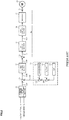
- A general configuration of the conventional electric power steering apparatus will be described with reference to
FIG. 1 . As shown inFIG. 1 , a column shaft (a steering shaft or a handle shaft) 2 connected to a handle (a steering wheel) 1 is connected to steeredwheels reduction gears 3,universal joints pinion mechanism 5, andtie rods 6a and 6b, further viahub units column shaft 2 is provided with atorque sensor 10 for detecting a steering torque Th of thesteering wheel 1 and asteering angle sensor 14 for detecting a steering angle θ, and amotor 20 for assisting a steering force of thesteering wheel 1 is connected to thecolumn shaft 2 through thereduction gears 3. The electric power is supplied to a control unit (ECU) 30 for controlling the electric power steering apparatus from abattery 13 as a power supply, and an ignition key (IG) signal is inputted into thecontrol unit 30 through anignition key 11. Thecontrol unit 30 calculates a current command value of an assist-control on the basis of the steering torque Th detected by thetorque sensor 10 and a vehicle speed Vel detected by avehicle speed sensor 12, and controls a current supplied to themotor 20 by means of a voltage control command value Vref obtained by performing compensation or the like to the calculated current command value. The steering angle θ can be obtained from a rotational sensor connected to themotor 20. - A controller area network (CAN) 40 to send/receive various information and signals on the vehicle is connected to the
control unit 30, and it is also possible to receive the vehicle speed Vel from the CAN 40. Further, a non-CAN 41 is also possible to connect to thecontrol unit 30, and the non-CAN 41 sends and receives a communication, analogue/digital signals, electric wave or the like except for the CAN 40. - In such an electric power steering apparatus, the
control unit 30 mainly comprises an MCU (including a CPU, an MPU and the like), and general functions performed by programs within the MCU are, for example, shown inFIG. 2 . Functions and operations of thecontrol unit 30 will be described with reference toFIG. 2 . The steering torque Th from thetorque sensor 10 and the vehicle speed Vel from the vehicle speed sensor 12 (or from the CAN 40) are inputted into a current commandvalue calculating section 31. The current commandvalue calculating section 31 calculates a current command value Iref1 based on the steering torque Th and the vehicle speed Vel using an assist map or the like. The calculated current command value Iref1 is added with a compensation signal CM for improving characteristics from a compensatingsection 34 at an addingsection 32A. The current command value Iref2 after the addition is limited of the maximum value thereof at a current limitingsection 33. The current command value Irefm limited of the maximum value is inputted into a subtractingsection 32B, whereat a detected motor current value Im is subtracted from the current command value Irefm. - The subtraction result I (= Irefm - Im) in the subtracting
section 32B is proportional-integral-controlled (PI-controlled) at a PI-control section 35. The voltage control command value Vref obtained by the PI-control and a modulation signal (a carrier) CF are inputted into a PWM-control section 36, whereat a duty thereof is calculated. Themotor 20 is PWM-driven by aninverter 37 with a PWM signal calculated the duty. The motor current value Im of themotor 20 is detected by a motor current detection means 38 and is inputted into the subtractingsection 32B for the feedback. - The compensating
section 34 adds a self-aligning torque (SAT) detected or estimated and aninertia compensation value 342 at an addingsection 344. The addition result is further added with aconvergence control value 341 at an addingsection 345. The addition result is inputted into the addingsection 32A as the compensation signal CM, thereby to improve the control characteristics. - In a case that the
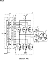
motor 20 is a three-phase brushless motor, details of the PWM-control section 36 and theinverter 37 have a configuration as shown inFIG. 3 , and the PWM-control section 36 comprises aduty calculating section 36A that is within the MCU and calculates duty signals D1 to D6 which are used in a three-phase PWM-control by using the voltage control command value Vref in accordance with a predetermined equation, and agate driving section 36B that drives the gates of the FETs as the semiconductor switching devices by means of the duty signals D1 to D6 and turns the gates on or off with compensating a dead time. The modulation signal (the carrier) CF is inputted into theduty calculating section 36A, and theduty calculating section 36A calculates the duty signals D1 to D6 of the PWM by synchronized to the modulation signal CF. - The
inverter 37 is configured to the three-phase bridges of theupper stage FET 1 toFET 3 and thelower stage FET 4 to FET 6. Thegate driving section 36B turns theFET 1 to the FET 6 on or of f by means of the duty signals D1 to D6 of the PWM respectively, so that themotor 20 is driven. TheFET 1 to the FET 6 are the FET with a back flow preventing parasitic diode. - A
motor opening switch 23 is interposed between theinverter 37 and themotor 20 in order to interrupt a current supply when the assist-control is stopped and the like. Themotor opening switch 23 comprises the FETs with the parasitic diode disposed to respective phases. - In such an electric power steering apparatus, conventionally, a system that detects the abnormality (including the failure) of the MCU is disclosed in, for example, an apparatus described in Japanese Unexamined Patent Publication No.
2003-26024 A Patent Document 1, as shown inFIG. 4 , in order to prevent from dangerous operation when theMCU 100A is abnormal, aWDT 110 serving as the abnormal detecting circuit is disposed in the external of theMCU 100A, theWDT 110 outputs a reset signal RS when detecting the abnormality of theMCU 100A, and areset circuit 120 that arranges a shape of the reset signal RS and resets theMCU 100A, is provided. The electric power from a power supply generatingcircuit 130 is supplied to theMCU 100A. The steering torque Th, the vehicle speed Vel, the steering angle θ and the like are inputted into theMCU 100A. TheMCU 100A drives and controls themotor 20 by using the calculated duty signals D1 to D6 of the PWM for driving the FETs through thegate driving section 36B and theinverter 37. - The
external WDT 110 inputs an abnormal detecting signal from theMCU 100A, outputs the reset signal RS in a case of detecting the abnormal signal, resets theMCU 100A through thereset circuit 120, and stops theMCU 100A and the system, so that the safety is secured. - Patent Document 1: Japanese Unexamined Patent Publication No.
2003-26024 A - However, the recent MCU with function safety has a safety function, and a hardware self-diagnostic function (a hardware BIST (a self-diagnostic circuit)) judging whether the safety function normally operates or not is incorporated in the MCU. There exists a restriction that a signal to the external WDT cannot be outputted while software cannot operate during executing the BIST. On the other hand, in a case that the external WDT operates while the BIST is executed, the signal from the MCU cannot be inputted, and then there is a possibility that the external WDT erroneously detects the abnormality of the MCU. It is required that the function of the external WDT is set to a disable state (Disable) while the BIST is executed.
- In a case that the MCU is failed in starting when the function of the external WDT is the disable state considering that the BIST is executed in starting the MCU, there is a problem that the external WDT cannot detect the abnormality of the MCU and the possibility that the system reaches the dangerous operation exists.
- The present invention has been developed in view of the above-described circumstances, and an object of the present invention is to provide an electronic control unit where an external WDT can always normally detect an abnormality (a failure) to an MCU having a BIST function or an MCU which cooperates with an external circuit having the BIST function and which can maintain safety of a system, and an electric power steering apparatus equipped with the electronic control unit.
- The present invention relates to an electronic control unit that is controlled by a micro controller unit (an MCU) via an inverter constituted by a semiconductor switching device, the above-described object of the present invention is achieved by that comprising: an external watch dog timer (an external WDT) to detect an abnormality of the MCU, a reset circuit to reset the MCU when the external WDT detects the abnormality of the MCU, and an ON/OFF control section to turn a gate of the semiconductor switching device on or off in accordance with the external WDT, wherein the inverter is stopped by turning the gate off via the ON/OFF control section when the external WDT is a disable state, and wherein when the abnormality of the MCU is not detected in an enable state to which the external WDT transits from the disable state, the inverter is driven by turning the gate on via the ON/OFF control section, and when the abnormality of the MCU is detected, the inverter is stopped by turning the gate off via the ON/OFF control section and the MCU is reset by the reset circuit.
- The above-described object of the present invention is efficiently achieved by that wherein the MCU has a built-in self-test (BIST) function, or the MCU cooperates with an external circuit having the BIST function; or wherein the semiconductor switching device is a field effect transistor (an FET) ; or wherein the external WDT is initiated in the disable state, and transits to the enable state based on a pulse signal from the MCU; or wherein the external WDT comprises a control terminal for the disable state/the enable-state, and transits to the enable state by operating the control terminal from the MCU; or wherein the external WDT is initiated in the disable state, and transits to the enable state based on a serial peripheral interface (SPI) communication with the MCU.
- The above-described object of the present invention is achieved by an electric power steering apparatus that is equipped with the above each electronic control unit.
- The electronic control unit of the present invention is provided with the external WDT which monitors the operation of the MCU having the BIST function or the MCU cooperating with the external circuit having the BIST function, drives the motor for the assist-control via the gate driving section constituted by the FET bridges and the inverter on the basis of the control signal from the MCU, and stops the inverter by outputting a driving stop signal to the gate driving section (a gate OFF signal) regardless of whether the abnormality (the failure) of the MCU occurs or not in a case that the external WDT is the disable state (Disable). The electronic control unit makes the external WDT transit from the disable state to the enable state (Enable) under the predetermined condition, it drives the inverter by outputting a gate ON signal in a case that the abnormality of the MCU is not detected when the external WDT is the enable state, and in a case that the abnormality of the MCU is detected when the external WDT is the enable state, it stops the inverter by outputting the gate OFF signal and resets the MCU. Thus, it is possible to maintain the safety of the system.
- Since the output driver is stopped by turning the gate off even when the external WDT is the disable state (Disable) and the failure of the MCU occurs, the electronic control unit has the effect that the system can maintain the safety. The pulse signal having a constant period from the MCU or the like is used for judging whether a condition that the external WDT transits to the enable state (Enable) issatisfiedor not. Since the external WDT can transit to the enable state (Enable) (release of the state of turning the gate off) by confirming that the MCU normally operates, the electronic control unit has the effect that the FET driving and the motor driving can be safely initiated.
- In the accompanying drawings:
-
FIG. 1 is a configuration diagram showing a general outline of an electric power steering apparatus; -
FIG. 2 is a block diagram showing a configuration example of a control system of the electric power steering apparatus; -
FIG. 3 is a circuit diagram showing a configuration example of a general PWM-control section and an inverter; -
FIG. 4 is a circuit diagram showing a configuration example of the inverter having a conventional protection function; -
FIG. 5 is a block diagram showing a configuration example of the present invention; -
FIG. 6 is a block diagram showing a configuration example of a gate driving section; and -
FIG. 7 is a flowchart showing an operating example of the present invention. - The present invention is an electronic control unit that is controlled by an MCU via an inverter constituted by semiconductor switching devices. An electric power steering apparatus equipped with the electronic control unit PWM-drives and controls a motor by an MCU having a BIST function or an MCU cooperating with an external circuit having the BIST function, and applies an assist torque to a steering system of a vehicle. The inverter that is constituted by FET bridges as the semiconductor switching devices is used in driving the motor . The electronic control unit comprises an external WDT that detects an abnormality (including a failure) of the MCU, and an ON/OFF control section that turns gates of the respective FETs in the inverter on or off by using a signal from the external WDT. The inverter is stopped by turning the gates of the FETs off, regardless of whether the abnormality (including the failure) of the MCU occurs or not, in a case that the external WDT is a disable state (Disable) . The external WDT transits from the disable state (Disable) to an enable state (Enable) when a predetermined condition is satisfied. In a case that the external WDT is the enable state and does not detect the abnormality of the MCU, the inverter is driven by turning the gates of the FETs on. In a case that the external WDT is the enable state and detects the abnormality of the MCU, the inverter is stopped by turning the gates of the FETs off and the MCU is reset. Thereby, the safety of the system can be maintained.
- Hereinafter, an embodiment of the present invention will be described with reference to the accompanying drawings. In the present embodiment, the electric power steering apparatus equipped with the electronic control unit will be described.
- As shown in
FIG. 5 corresponding toFIG. 4 , in the present invention, anMCU 100 having the BIST function performs an overall control. The electronic control unit comprises anexternal WDT 110 that detects the abnormality of theMCU 100, areset circuit 120 that resets theMCU 100 on the basis of a reset signal RS which theexternal WDT 110 outputs, and an ON/OFF control section 140 that outputs a gate signal RSG which turns gates of agate driving section 36B on or off on the basis of presence or absence of the reset signal RS. - As shown in
FIG. 6 , in thegate driving section 36B, duty signals D1 to D6 from theMCU 100 input into "AND" circuits 36-1 to 36-6 respectively. The gate signal RSG is also inputted into the "AND" circuits 36-1 to 36-6. Since the "AND" circuits 36-1 to 36-6 output driving signals D1A to D6A under an "AND" condition, when the gate signal RSG is inputted, the outputs of the driving signals D1A to D6A from the "AND" circuits 36-1 to 36-6 are all OFF, and the inverter is stopped driving. When the gate signal RSG is not inputted into the "AND" circuits 36-1 to 36-6, the calculated duty signals D1 to D6 are outputted as the driving signals D1A to D6A from the "AND" circuits 36-1 to 36-6, and the inverter is driven by using the duty signals D1 to D6. - In such a configuration, an operating example will be described with reference to a flowchart of
FIG. 7 . - When starting the power supply, the
MCU 100 executes a hardware BIST that checks whether a safety function incorporated in theMCU 100 normally operates or not (Step S1). Because software cannot operate during executing the hardware BIST, terminals of theMCU 100 are initial setting states during the BIST. On the other hand, in order to prevent from erroneous detection due to not detecting the signals from theMCU 100 during executing the BIST of theMCU 100, theexternal WDT 110 starts in the disable state (Disable) (Step S2), outputs the gate signal RSG to the gateFET driving section 36B via the ON/OFF control section 140, and stops the driving of theinverter 37 by turning the FET1 to the FET6 off (Step S3) . - After completing the hardware BIST (Step S4), when the software normally operates, the pulse signal having a constant period, which indicates that the
MCU 100 normally operates, is outputted from theMCU 100 to the external WDT 110 (Step S5). In a case that theexternal WDT 110 detects the pulse signal having the constant period and can judge that theMCU 100 normally operates, the function of theexternal WDT 110 transits from the disable state (Disable) to the enable state (Enable) (Step S10), the gate signal RSG is released via the ON/OFF control section 140 (Step S11), and theexternal WDT 110 continues diagnosing the operation of the MCU 100 (Step S12). - After the
external WDT 110 transits to the enable state (Enable), in a case that the abnormality of theMCU 100 is not detected and theMCU 100 normally operates, the gate signal RSG is set to "gate ON" via the ON/OFF control section 140 (Step S15), theinverter 37 is driven (Step S16), and the above driving operation is continued. - On the other hand, in a case that the
MCU 100 is failed and cannot detect the pulse signal having the constant in the above Step S13, theexternal WDT 110 detects the abnormality of theMCU 100. When theexternal WDT 110 detects the abnormality of theMCU 100, theWDT 110 outputs the reset signal RS, the gate signal RSG is set to "gate OFF" via the ON/OFF control section 140, and the driving of theinverter 37 is stopped by turning the FET1 to the FET6 off (Step S20). Further, theMCU 100 is reset via the reset circuit 120 (Step S21), and the driving is stopped (Step S22) . - In a case that the
MCU 110 is failed or is abnormal when starting the power supply and theMCU 110 abnormally operates, since the software cannot normally operate regardless of whether the BIST is executed or not, theMCU 100 cannot output the pulse signal having the constant period (Step S5). Then, theexternal WDT 110 does not transit from the disable state (Disable) to the enable state (Enable), and the gates continue to be turned off by the gate signal RSG (Step S3). - As described above, even in a case that the
external WDT 110 is the disable state (Disable) and the failure of theMCU 100 is occurred, since the gates are turned off by the gate signal RSG and the output driver is stopped, there exists the effect that the system can maintain the safety. The pulse signal from theMCU 100 is used for judging whether a condition that theexternal WDT 110 transits to the enable state (Enable) is satisfied or not. Since theexternal WDT 110 can transit to the enable state (Enable) (release of the gate signal RSG) by confirming that theMCU 100 normally operates, there exists the effect that the FET driving and the motor driving can be safely initiated. In the present embodiment, the pulse signal having the constant period from the MCU is used for judging whether a condition that the external WDT transits to the enable state (Enable) is satisfied or not. Alternatively, a control terminal for setting the disable state (Disable) or the enable state (Enable) is disposed in the external WDT, and the MCU may operate the control terminal. As another method, the disable state (Disable) or the enable state (Enable) in the external WDT may be set by serial peripheral interface (SPI) communication. - The electronic control unit of the present invention is not limited to use the electric power steering apparatus, and can be applied to, for example, a vehicle-mounted control device, and a general electronic control unit that drives the motor or the actuator.
- Further, as described above, the MCU itself has the BIST function. The MCU that cooperates with the circuit having the BIST function may be used.
-
- 1
- handle (steering wheel)
- 2
- column shaft (steering shaft, handle shaft)
- 10
- torque sensor
- 12
- vehicle speed sensor
- 13
- battery
- 20
- motor
- 23
- motor opening switch
- 30
- control unit (ECU)
- 31
- current command value calculating section
- 35
- PI-control section
- 36
- PWM-control section
- 37
- inverter
- 100
- micro controller unit (MCU)
- 110
- watch dog timer (WDT)
- 120
- reset circuit
- 130
- power supply generating circuit
- 140
- ON/OFF control section
Claims (7)
- An electronic control unit that is controlled by a micro controller unit (an MCU) via an inverter constituted by a semiconductor switching device, comprising:an external watch dog timer (an external WDT) to detect an abnormality of said MCU,a reset circuit to reset said MCU when said external WDT detects said abnormality of said MCU, andan ON/OFF control section to turn a gate of said semiconductor switching device on or off in accordance with said external WDT,wherein said inverter is stopped by turning said gate off via said ON/OFF control section when said external WDT is a disable state, andwherein when said abnormality of said MCU is not detected in an enable state to which said external WDT transits from said disable state, said inverter is driven by turning said gate on via said ON/OFF control section, and when said abnormality of said MCU is detected, said inverter is stopped by turning said gate off via said ON/OFF control section and said MCU is reset by said reset circuit.
- The electronic control unit according to Claim 1, wherein said MCU has a built-in self-test (BIST) function, or said MCU cooperates with an external circuit having said BIST function.
- The electronic control unit according to Claim 1 or 2, wherein said semiconductor switching device is a field effect transistor (an FET).
- The electronic control unit according to any one of Claims 1 to 3, wherein said external WDT is initiated in said disable state, and transits to said enable state based on a pulse signal from said MCU.
- The electronic control unit according to any one of Claims 1 to 3, wherein said external WDT comprises a control terminal for said disable state/said enable-state, and transits to said enable state by operating said control terminal from said MCU.
- The electronic control unit according to any one of Claims 1 to 3, wherein said external WDT is initiated in said disable state, and transits to said enable state based on a serial peripheral interface (SPI) communication with said MCU.
- An electric power steering apparatus that is equipped with said electronic control unit according to any one of Claims 1 to 6, drives and controls a motor by said MCU via said inverter based on a current command value served as a steering command, and applies an assist torque to a steering system of a vehicle by said motor.
Applications Claiming Priority (2)
| Application Number | Priority Date | Filing Date | Title |
|---|---|---|---|
| JP2015229025 | 2015-11-24 | ||
| PCT/JP2016/084602 WO2017090612A1 (en) | 2015-11-24 | 2016-11-22 | Electronic control device and electric power steering device equipped therewith |
Publications (3)
| Publication Number | Publication Date |
|---|---|
| EP3382877A1 true EP3382877A1 (en) | 2018-10-03 |
| EP3382877A4 EP3382877A4 (en) | 2019-07-24 |
| EP3382877B1 EP3382877B1 (en) | 2021-04-14 |
Family
ID=58764132
Family Applications (1)
| Application Number | Title | Priority Date | Filing Date |
|---|---|---|---|
| EP16868555.0A Active EP3382877B1 (en) | 2015-11-24 | 2016-11-22 | Electronic control device and electric power steering device equipped therewith |
Country Status (7)
| Country | Link |
|---|---|
| US (1) | US10471984B2 (en) |
| EP (1) | EP3382877B1 (en) |
| JP (1) | JP6550469B2 (en) |
| KR (1) | KR102051765B1 (en) |
| CN (1) | CN108702099B (en) |
| BR (1) | BR112018010214B1 (en) |
| WO (1) | WO2017090612A1 (en) |
Families Citing this family (4)
| Publication number | Priority date | Publication date | Assignee | Title |
|---|---|---|---|---|
| US10435007B2 (en) * | 2015-09-23 | 2019-10-08 | Cummins, Inc. | Systems and methods of engine stop/start control of an electrified powertrain |
| KR102322483B1 (en) * | 2017-07-20 | 2021-11-08 | 현대모비스 주식회사 | Apparatus for controlling entry of safe state in motor driven power supply system and method thereof |
| CN113085566B (en) * | 2021-04-21 | 2022-08-23 | 苏州汇川联合动力系统有限公司 | Motor controller safety state switching circuit, device and control method |
| KR20220147992A (en) * | 2021-04-28 | 2022-11-04 | 현대자동차주식회사 | Apparatus and method for controlling power of vehicle |
Family Cites Families (12)
| Publication number | Priority date | Publication date | Assignee | Title |
|---|---|---|---|---|
| WO1998058382A1 (en) * | 1997-06-16 | 1998-12-23 | Hitachi, Ltd. | Semiconductor integrated circuit device |
| JP4029522B2 (en) * | 1999-07-02 | 2008-01-09 | 日本精工株式会社 | Control device for electric power steering device |
| JP3968972B2 (en) * | 2000-08-14 | 2007-08-29 | 日本精工株式会社 | Control device for electric power steering device |
| JP2002332909A (en) * | 2001-05-08 | 2002-11-22 | Kokusan Denki Co Ltd | Control device for vehicle drive device |
| JP2002354871A (en) * | 2001-05-25 | 2002-12-06 | Mitsubishi Electric Corp | Electric power steering device |
| JP2003026024A (en) | 2001-07-17 | 2003-01-29 | Omron Corp | Control device for electric power steering |
| JP2009251680A (en) * | 2008-04-01 | 2009-10-29 | Toshiba Tec Corp | Method and program for starting information processor |
| CN103561993B (en) * | 2011-05-31 | 2016-03-02 | 丰田自动车株式会社 | The control method of vehicle and vehicle |
| JP5403010B2 (en) * | 2011-08-08 | 2014-01-29 | 株式会社デンソー | Capacitor discharge circuit |
| JP5892394B2 (en) * | 2014-01-28 | 2016-03-23 | 株式会社デンソー | Power conversion device and electric power steering device using the same |
| JP2015153343A (en) * | 2014-02-19 | 2015-08-24 | キヤノン株式会社 | Runaway monitoring device and control system |
| JP6341795B2 (en) * | 2014-08-05 | 2018-06-13 | ルネサスエレクトロニクス株式会社 | Microcomputer and microcomputer system |
-
2016
- 2016-11-22 KR KR1020187013992A patent/KR102051765B1/en active IP Right Grant
- 2016-11-22 EP EP16868555.0A patent/EP3382877B1/en active Active
- 2016-11-22 US US15/776,907 patent/US10471984B2/en active Active
- 2016-11-22 CN CN201680067660.9A patent/CN108702099B/en active Active
- 2016-11-22 JP JP2017552664A patent/JP6550469B2/en active Active
- 2016-11-22 BR BR112018010214-8A patent/BR112018010214B1/en active IP Right Grant
- 2016-11-22 WO PCT/JP2016/084602 patent/WO2017090612A1/en active Application Filing
Also Published As
| Publication number | Publication date |
|---|---|
| US10471984B2 (en) | 2019-11-12 |
| KR102051765B1 (en) | 2019-12-03 |
| EP3382877A4 (en) | 2019-07-24 |
| US20180339726A1 (en) | 2018-11-29 |
| BR112018010214A2 (en) | 2019-02-12 |
| CN108702099A (en) | 2018-10-23 |
| JPWO2017090612A1 (en) | 2018-09-06 |
| EP3382877B1 (en) | 2021-04-14 |
| CN108702099B (en) | 2020-09-15 |
| JP6550469B2 (en) | 2019-07-24 |
| BR112018010214B1 (en) | 2022-08-30 |
| KR20180073615A (en) | 2018-07-02 |
| WO2017090612A1 (en) | 2017-06-01 |
Similar Documents
| Publication | Publication Date | Title |
|---|---|---|
| JP6593508B2 (en) | Motor control device and electric power steering device equipped with the same | |
| CN109314483B (en) | Motor control device, and electric power steering device and vehicle equipped with same | |
| US7091684B2 (en) | Electric power steering apparatus | |
| EP3340457B1 (en) | Electronic control device and electric power steering device equipped with same | |
| US6687590B2 (en) | Electric power steering apparatus | |
| EP3382877B1 (en) | Electronic control device and electric power steering device equipped therewith | |
| KR100798222B1 (en) | Electric power steering control apparatus | |
| WO2003078237A1 (en) | Electric power steering device control apparatus | |
| US11273862B2 (en) | Steering control device | |
| JP6497456B2 (en) | Control device for electric power steering device | |
| JP2009046044A (en) | Control device for electric power steering device | |
| JP6287644B2 (en) | Control device for electric power steering device | |
| JP2019054612A (en) | Motor controller and electrically-driven power steering device mounting the same |
Legal Events
| Date | Code | Title | Description |
|---|---|---|---|
| STAA | Information on the status of an ep patent application or granted ep patent |
Free format text: STATUS: THE INTERNATIONAL PUBLICATION HAS BEEN MADE |
|
| PUAI | Public reference made under article 153(3) epc to a published international application that has entered the european phase |
Free format text: ORIGINAL CODE: 0009012 |
|
| STAA | Information on the status of an ep patent application or granted ep patent |
Free format text: STATUS: REQUEST FOR EXAMINATION WAS MADE |
|
| 17P | Request for examination filed |
Effective date: 20180517 |
|
| AK | Designated contracting states |
Kind code of ref document: A1 Designated state(s): AL AT BE BG CH CY CZ DE DK EE ES FI FR GB GR HR HU IE IS IT LI LT LU LV MC MK MT NL NO PL PT RO RS SE SI SK SM TR |
|
| AX | Request for extension of the european patent |
Extension state: BA ME |
|
| DAV | Request for validation of the european patent (deleted) | ||
| DAX | Request for extension of the european patent (deleted) | ||
| A4 | Supplementary search report drawn up and despatched |
Effective date: 20190626 |
|
| RIC1 | Information provided on ipc code assigned before grant |
Ipc: B62D 5/04 20060101ALI20190619BHEP Ipc: H02M 7/48 20070101AFI20190619BHEP Ipc: H02P 27/06 20060101ALI20190619BHEP |
|
| GRAP | Despatch of communication of intention to grant a patent |
Free format text: ORIGINAL CODE: EPIDOSNIGR1 |
|
| STAA | Information on the status of an ep patent application or granted ep patent |
Free format text: STATUS: GRANT OF PATENT IS INTENDED |
|
| INTG | Intention to grant announced |
Effective date: 20201210 |
|
| RIN1 | Information on inventor provided before grant (corrected) |
Inventor name: ANDO, NOBUHIKO Inventor name: YAMAZAKI, TAKAHIRO Inventor name: URYU, KYOSHO Inventor name: KUMAGAI, SHIN |
|
| GRAS | Grant fee paid |
Free format text: ORIGINAL CODE: EPIDOSNIGR3 |
|
| GRAA | (expected) grant |
Free format text: ORIGINAL CODE: 0009210 |
|
| STAA | Information on the status of an ep patent application or granted ep patent |
Free format text: STATUS: THE PATENT HAS BEEN GRANTED |
|
| AK | Designated contracting states |
Kind code of ref document: B1 Designated state(s): AL AT BE BG CH CY CZ DE DK EE ES FI FR GB GR HR HU IE IS IT LI LT LU LV MC MK MT NL NO PL PT RO RS SE SI SK SM TR |
|
| REG | Reference to a national code |
Ref country code: GB Ref legal event code: FG4D |
|
| REG | Reference to a national code |
Ref country code: CH Ref legal event code: EP |
|
| REG | Reference to a national code |
Ref country code: DE Ref legal event code: R096 Ref document number: 602016056263 Country of ref document: DE |
|
| REG | Reference to a national code |
Ref country code: IE Ref legal event code: FG4D |
|
| REG | Reference to a national code |
Ref country code: AT Ref legal event code: REF Ref document number: 1383357 Country of ref document: AT Kind code of ref document: T Effective date: 20210515 |
|
| REG | Reference to a national code |
Ref country code: LT Ref legal event code: MG9D |
|
| REG | Reference to a national code |
Ref country code: AT Ref legal event code: MK05 Ref document number: 1383357 Country of ref document: AT Kind code of ref document: T Effective date: 20210414 |
|
| REG | Reference to a national code |
Ref country code: NL Ref legal event code: MP Effective date: 20210414 |
|
| PG25 | Lapsed in a contracting state [announced via postgrant information from national office to epo] |
Ref country code: NL Free format text: LAPSE BECAUSE OF FAILURE TO SUBMIT A TRANSLATION OF THE DESCRIPTION OR TO PAY THE FEE WITHIN THE PRESCRIBED TIME-LIMIT Effective date: 20210414 Ref country code: AT Free format text: LAPSE BECAUSE OF FAILURE TO SUBMIT A TRANSLATION OF THE DESCRIPTION OR TO PAY THE FEE WITHIN THE PRESCRIBED TIME-LIMIT Effective date: 20210414 Ref country code: BG Free format text: LAPSE BECAUSE OF FAILURE TO SUBMIT A TRANSLATION OF THE DESCRIPTION OR TO PAY THE FEE WITHIN THE PRESCRIBED TIME-LIMIT Effective date: 20210714 Ref country code: HR Free format text: LAPSE BECAUSE OF FAILURE TO SUBMIT A TRANSLATION OF THE DESCRIPTION OR TO PAY THE FEE WITHIN THE PRESCRIBED TIME-LIMIT Effective date: 20210414 Ref country code: FI Free format text: LAPSE BECAUSE OF FAILURE TO SUBMIT A TRANSLATION OF THE DESCRIPTION OR TO PAY THE FEE WITHIN THE PRESCRIBED TIME-LIMIT Effective date: 20210414 Ref country code: LT Free format text: LAPSE BECAUSE OF FAILURE TO SUBMIT A TRANSLATION OF THE DESCRIPTION OR TO PAY THE FEE WITHIN THE PRESCRIBED TIME-LIMIT Effective date: 20210414 |
|
| PG25 | Lapsed in a contracting state [announced via postgrant information from national office to epo] |
Ref country code: NO Free format text: LAPSE BECAUSE OF FAILURE TO SUBMIT A TRANSLATION OF THE DESCRIPTION OR TO PAY THE FEE WITHIN THE PRESCRIBED TIME-LIMIT Effective date: 20210714 Ref country code: PT Free format text: LAPSE BECAUSE OF FAILURE TO SUBMIT A TRANSLATION OF THE DESCRIPTION OR TO PAY THE FEE WITHIN THE PRESCRIBED TIME-LIMIT Effective date: 20210816 Ref country code: PL Free format text: LAPSE BECAUSE OF FAILURE TO SUBMIT A TRANSLATION OF THE DESCRIPTION OR TO PAY THE FEE WITHIN THE PRESCRIBED TIME-LIMIT Effective date: 20210414 Ref country code: SE Free format text: LAPSE BECAUSE OF FAILURE TO SUBMIT A TRANSLATION OF THE DESCRIPTION OR TO PAY THE FEE WITHIN THE PRESCRIBED TIME-LIMIT Effective date: 20210414 Ref country code: RS Free format text: LAPSE BECAUSE OF FAILURE TO SUBMIT A TRANSLATION OF THE DESCRIPTION OR TO PAY THE FEE WITHIN THE PRESCRIBED TIME-LIMIT Effective date: 20210414 Ref country code: LV Free format text: LAPSE BECAUSE OF FAILURE TO SUBMIT A TRANSLATION OF THE DESCRIPTION OR TO PAY THE FEE WITHIN THE PRESCRIBED TIME-LIMIT Effective date: 20210414 Ref country code: GR Free format text: LAPSE BECAUSE OF FAILURE TO SUBMIT A TRANSLATION OF THE DESCRIPTION OR TO PAY THE FEE WITHIN THE PRESCRIBED TIME-LIMIT Effective date: 20210715 Ref country code: IS Free format text: LAPSE BECAUSE OF FAILURE TO SUBMIT A TRANSLATION OF THE DESCRIPTION OR TO PAY THE FEE WITHIN THE PRESCRIBED TIME-LIMIT Effective date: 20210814 |
|
| REG | Reference to a national code |
Ref country code: DE Ref legal event code: R097 Ref document number: 602016056263 Country of ref document: DE |
|
| PG25 | Lapsed in a contracting state [announced via postgrant information from national office to epo] |
Ref country code: RO Free format text: LAPSE BECAUSE OF FAILURE TO SUBMIT A TRANSLATION OF THE DESCRIPTION OR TO PAY THE FEE WITHIN THE PRESCRIBED TIME-LIMIT Effective date: 20210414 Ref country code: ES Free format text: LAPSE BECAUSE OF FAILURE TO SUBMIT A TRANSLATION OF THE DESCRIPTION OR TO PAY THE FEE WITHIN THE PRESCRIBED TIME-LIMIT Effective date: 20210414 Ref country code: CZ Free format text: LAPSE BECAUSE OF FAILURE TO SUBMIT A TRANSLATION OF THE DESCRIPTION OR TO PAY THE FEE WITHIN THE PRESCRIBED TIME-LIMIT Effective date: 20210414 Ref country code: DK Free format text: LAPSE BECAUSE OF FAILURE TO SUBMIT A TRANSLATION OF THE DESCRIPTION OR TO PAY THE FEE WITHIN THE PRESCRIBED TIME-LIMIT Effective date: 20210414 Ref country code: EE Free format text: LAPSE BECAUSE OF FAILURE TO SUBMIT A TRANSLATION OF THE DESCRIPTION OR TO PAY THE FEE WITHIN THE PRESCRIBED TIME-LIMIT Effective date: 20210414 Ref country code: SM Free format text: LAPSE BECAUSE OF FAILURE TO SUBMIT A TRANSLATION OF THE DESCRIPTION OR TO PAY THE FEE WITHIN THE PRESCRIBED TIME-LIMIT Effective date: 20210414 Ref country code: SK Free format text: LAPSE BECAUSE OF FAILURE TO SUBMIT A TRANSLATION OF THE DESCRIPTION OR TO PAY THE FEE WITHIN THE PRESCRIBED TIME-LIMIT Effective date: 20210414 |
|
| PLBE | No opposition filed within time limit |
Free format text: ORIGINAL CODE: 0009261 |
|
| STAA | Information on the status of an ep patent application or granted ep patent |
Free format text: STATUS: NO OPPOSITION FILED WITHIN TIME LIMIT |
|
| 26N | No opposition filed |
Effective date: 20220117 |
|
| PG25 | Lapsed in a contracting state [announced via postgrant information from national office to epo] |
Ref country code: IS Free format text: LAPSE BECAUSE OF FAILURE TO SUBMIT A TRANSLATION OF THE DESCRIPTION OR TO PAY THE FEE WITHIN THE PRESCRIBED TIME-LIMIT Effective date: 20210814 Ref country code: AL Free format text: LAPSE BECAUSE OF FAILURE TO SUBMIT A TRANSLATION OF THE DESCRIPTION OR TO PAY THE FEE WITHIN THE PRESCRIBED TIME-LIMIT Effective date: 20210414 |
|
| PG25 | Lapsed in a contracting state [announced via postgrant information from national office to epo] |
Ref country code: MC Free format text: LAPSE BECAUSE OF FAILURE TO SUBMIT A TRANSLATION OF THE DESCRIPTION OR TO PAY THE FEE WITHIN THE PRESCRIBED TIME-LIMIT Effective date: 20210414 |
|
| REG | Reference to a national code |
Ref country code: CH Ref legal event code: PL |
|
| GBPC | Gb: european patent ceased through non-payment of renewal fee |
Effective date: 20211122 |
|
| PG25 | Lapsed in a contracting state [announced via postgrant information from national office to epo] |
Ref country code: LU Free format text: LAPSE BECAUSE OF NON-PAYMENT OF DUE FEES Effective date: 20211122 Ref country code: IT Free format text: LAPSE BECAUSE OF FAILURE TO SUBMIT A TRANSLATION OF THE DESCRIPTION OR TO PAY THE FEE WITHIN THE PRESCRIBED TIME-LIMIT Effective date: 20210414 Ref country code: BE Free format text: LAPSE BECAUSE OF NON-PAYMENT OF DUE FEES Effective date: 20211130 |
|
| REG | Reference to a national code |
Ref country code: BE Ref legal event code: MM Effective date: 20211130 |
|
| PG25 | Lapsed in a contracting state [announced via postgrant information from national office to epo] |
Ref country code: IE Free format text: LAPSE BECAUSE OF NON-PAYMENT OF DUE FEES Effective date: 20211122 Ref country code: GB Free format text: LAPSE BECAUSE OF NON-PAYMENT OF DUE FEES Effective date: 20211122 |
|
| PG25 | Lapsed in a contracting state [announced via postgrant information from national office to epo] |
Ref country code: HU Free format text: LAPSE BECAUSE OF FAILURE TO SUBMIT A TRANSLATION OF THE DESCRIPTION OR TO PAY THE FEE WITHIN THE PRESCRIBED TIME-LIMIT; INVALID AB INITIO Effective date: 20161122 |
|
| PG25 | Lapsed in a contracting state [announced via postgrant information from national office to epo] |
Ref country code: CY Free format text: LAPSE BECAUSE OF FAILURE TO SUBMIT A TRANSLATION OF THE DESCRIPTION OR TO PAY THE FEE WITHIN THE PRESCRIBED TIME-LIMIT Effective date: 20210414 |
|
| PG25 | Lapsed in a contracting state [announced via postgrant information from national office to epo] |
Ref country code: LI Free format text: LAPSE BECAUSE OF NON-PAYMENT OF DUE FEES Effective date: 20220630 Ref country code: CH Free format text: LAPSE BECAUSE OF NON-PAYMENT OF DUE FEES Effective date: 20220630 |
|
| PGFP | Annual fee paid to national office [announced via postgrant information from national office to epo] |
Ref country code: FR Payment date: 20230929 Year of fee payment: 8 |
|
| PGFP | Annual fee paid to national office [announced via postgrant information from national office to epo] |
Ref country code: DE Payment date: 20230929 Year of fee payment: 8 |
|
| REG | Reference to a national code |
Ref country code: DE Ref legal event code: R081 Ref document number: 602016056263 Country of ref document: DE Owner name: TOSHIBA ELECTRONIC DEVICES & STORAGE CORPORATI, JP Free format text: FORMER OWNERS: NSK LTD., TOKYO, JP; TOSHIBA ELECTRONIC DEVICES & STORAGE CORPORATION, TOKYO, JP Ref country code: DE Ref legal event code: R081 Ref document number: 602016056263 Country of ref document: DE Owner name: NSK STEERING & CONTROL, INC., JP Free format text: FORMER OWNERS: NSK LTD., TOKYO, JP; TOSHIBA ELECTRONIC DEVICES & STORAGE CORPORATION, TOKYO, JP |