EP3382271B1 - Device for adapting the intensity of radiation - Google Patents
Device for adapting the intensity of radiation Download PDFInfo
- Publication number
- EP3382271B1 EP3382271B1 EP17163613.7A EP17163613A EP3382271B1 EP 3382271 B1 EP3382271 B1 EP 3382271B1 EP 17163613 A EP17163613 A EP 17163613A EP 3382271 B1 EP3382271 B1 EP 3382271B1
- Authority
- EP
- European Patent Office
- Prior art keywords
- neutral density
- filter
- radiation source
- density filters
- filters
- Prior art date
- Legal status (The legal status is an assumption and is not a legal conclusion. Google has not performed a legal analysis and makes no representation as to the accuracy of the status listed.)
- Active
Links
Images


Classifications
-
- G—PHYSICS
- G01—MEASURING; TESTING
- G01D—MEASURING NOT SPECIALLY ADAPTED FOR A SPECIFIC VARIABLE; ARRANGEMENTS FOR MEASURING TWO OR MORE VARIABLES NOT COVERED IN A SINGLE OTHER SUBCLASS; TARIFF METERING APPARATUS; MEASURING OR TESTING NOT OTHERWISE PROVIDED FOR
- G01D21/00—Measuring or testing not otherwise provided for
-
- G—PHYSICS
- G01—MEASURING; TESTING
- G01N—INVESTIGATING OR ANALYSING MATERIALS BY DETERMINING THEIR CHEMICAL OR PHYSICAL PROPERTIES
- G01N17/00—Investigating resistance of materials to the weather, to corrosion, or to light
- G01N17/004—Investigating resistance of materials to the weather, to corrosion, or to light to light
-
- F—MECHANICAL ENGINEERING; LIGHTING; HEATING; WEAPONS; BLASTING
- F21—LIGHTING
- F21V—FUNCTIONAL FEATURES OR DETAILS OF LIGHTING DEVICES OR SYSTEMS THEREOF; STRUCTURAL COMBINATIONS OF LIGHTING DEVICES WITH OTHER ARTICLES, NOT OTHERWISE PROVIDED FOR
- F21V9/00—Elements for modifying spectral properties, polarisation or intensity of the light emitted, e.g. filters
- F21V9/02—Elements for modifying spectral properties, polarisation or intensity of the light emitted, e.g. filters for simulating daylight
-
- F—MECHANICAL ENGINEERING; LIGHTING; HEATING; WEAPONS; BLASTING
- F21—LIGHTING
- F21S—NON-PORTABLE LIGHTING DEVICES; SYSTEMS THEREOF; VEHICLE LIGHTING DEVICES SPECIALLY ADAPTED FOR VEHICLE EXTERIORS
- F21S8/00—Lighting devices intended for fixed installation
- F21S8/006—Solar simulators, e.g. for testing photovoltaic panels
-
- F—MECHANICAL ENGINEERING; LIGHTING; HEATING; WEAPONS; BLASTING
- F21—LIGHTING
- F21V—FUNCTIONAL FEATURES OR DETAILS OF LIGHTING DEVICES OR SYSTEMS THEREOF; STRUCTURAL COMBINATIONS OF LIGHTING DEVICES WITH OTHER ARTICLES, NOT OTHERWISE PROVIDED FOR
- F21V9/00—Elements for modifying spectral properties, polarisation or intensity of the light emitted, e.g. filters
- F21V9/08—Elements for modifying spectral properties, polarisation or intensity of the light emitted, e.g. filters for producing coloured light, e.g. monochromatic; for reducing intensity of light
-
- G—PHYSICS
- G02—OPTICS
- G02B—OPTICAL ELEMENTS, SYSTEMS OR APPARATUS
- G02B26/00—Optical devices or arrangements for the control of light using movable or deformable optical elements
- G02B26/02—Optical devices or arrangements for the control of light using movable or deformable optical elements for controlling the intensity of light
- G02B26/023—Optical devices or arrangements for the control of light using movable or deformable optical elements for controlling the intensity of light comprising movable attenuating elements, e.g. neutral density filters
-
- G—PHYSICS
- G02—OPTICS
- G02B—OPTICAL ELEMENTS, SYSTEMS OR APPARATUS
- G02B5/00—Optical elements other than lenses
- G02B5/20—Filters
- G02B5/205—Neutral density filters
-
- G—PHYSICS
- G05—CONTROLLING; REGULATING
- G05D—SYSTEMS FOR CONTROLLING OR REGULATING NON-ELECTRIC VARIABLES
- G05D25/00—Control of light, e.g. intensity, colour or phase
-
- F—MECHANICAL ENGINEERING; LIGHTING; HEATING; WEAPONS; BLASTING
- F21—LIGHTING
- F21V—FUNCTIONAL FEATURES OR DETAILS OF LIGHTING DEVICES OR SYSTEMS THEREOF; STRUCTURAL COMBINATIONS OF LIGHTING DEVICES WITH OTHER ARTICLES, NOT OTHERWISE PROVIDED FOR
- F21V14/00—Controlling the distribution of the light emitted by adjustment of elements
- F21V14/08—Controlling the distribution of the light emitted by adjustment of elements by movement of the screens or filters
-
- G—PHYSICS
- G01—MEASURING; TESTING
- G01N—INVESTIGATING OR ANALYSING MATERIALS BY DETERMINING THEIR CHEMICAL OR PHYSICAL PROPERTIES
- G01N17/00—Investigating resistance of materials to the weather, to corrosion, or to light
- G01N17/002—Test chambers
Definitions
- the present disclosure relates to a device for adjusting the irradiance of light emitted by a radiation source, the use of a woven metal or noble beam wire as a neutral density filter in a device for adjusting the irradiance and the use of such a device in a device to check the effect of light radiation on an object.
- sun simulators Devices for simulating sunlight, also called sun simulators, have been known for some time.
- a sun simulator can be used to study the effects of sunlight on certain objects to be irradiated under laboratory conditions. Since natural sunlight is subject to strong fluctuations in time, the use of a sun simulator compared to field trials has the advantage that measurements can be carried out and also reproduced under defined, continuous, day and season-independent conditions.
- the application and application options for sun simulators range from small laboratory and walk-in chambers for component or assembly testing, through drive-in chambers for complete vehicles to large hall systems for trucks, trains or airplanes.
- the highest possible spectral correspondence of the artificial light source with the natural sunlight is crucial for the quality of the test conditions to be simulated and their reliable repeatability.
- spectral optical filters can be used to match the spectrum to that of sunlight.
- a device for adapting the irradiance comprises a radiation source and at least one neutral density filter movably arranged in front of the radiation source, the neutral density filter being able to be moved into the beam path of the radiation source or out of the beam path of the radiation source, and the device comprising the features according to claim 1.
- a computer program product is designed to control a device according to the first aspect.
- a woven metal or stainless steel wire is used as a neutral density filter in a device for adjusting the irradiance.
- a device for checking the effect of light radiation on an object comprises at least one device according to the first aspect and a device for receiving an object to be irradiated.
- Fig. 1 schematically shows a basic embodiment of an apparatus for adjusting the irradiance according to an example not claimed.
- the device 10 according to the first aspect accordingly has a radiation source 11 and at least one neutral density filter arranged movably in front of the radiation source 11 12 on.
- the neutral density filter 12 is arranged such that the radiation 14 emitted by the radiation source 11 passes through the neutral density filter 12.
- the neutral density filter 12 is movably arranged such that it can be moved into the beam path of the radiation source 11 or out of the beam path of the radiation source 11.
- the device 10 has at least one further neutral density filter 13 (dashed).
- This can be arranged to be movable in the same way as the neutral density filter 12 in or out of the beam path of the radiation source 11, in particular independently of the neutral density filter 12, as indicated by a further double arrow.
- the further neutral density filter 13 can be positioned in the beam path at a different position than the neutral density filter 12, so that the two neutral density filters 12 and 13 can be arranged one behind the other in the beam path.
- the neutral density filters 12 and 13 can have the same or different degrees of density and thus degrees of transmission, in the latter case depending on the position of the neutral density filters 12 and 13 in the beam path or outside of it four different amounts of the irradiance in the beam path can be set behind the neutral density filters 12 and 13.
- the radiation source 11 has a housing 11.1 and a light source 11.2 fastened in the housing 11.1.
- the light source 11.2 is designed in such a way that it emits a spectrum which approximates the solar spectrum as far as possible.
- suitable optical filters can be arranged in or outside the housing 11.1 in order to further improve the approximation of the spectrum to the solar spectrum.
- the light source 11.2 can be provided by a metal halide lamp.
- the light source 11.2 can be provided by a xenon lamp.
- the at least one neutral density filter 12 has a woven metal or noble beam wire.
- the transmittance of such a neutral density filter can be adjusted via the density of the tissue.
- the woven metal or noble beam wire can be blackened.
- the at least one neutral density filter 12 has a perforated film or a perforated plate.
- the degree of transmission of such a neutral density filter in the case of equidistantly perforated foils or sheets can be determined by the size of the Holes or the ratio of hole area to total area can be set.
- the film or the sheet can be blackened.
- the at least one neutral density filter 12 can also be provided by neutral or gray glasses or neutral reflection filters.
- the light output of the light source 11.2 can be regulated or dimmed.
- the light output can be regulated by means of a control device such as an electrical ballast.
- the at least one neutral density filter 12 is arranged along a curved surface. According to the invention, the at least one neutral density filter 12 is arranged along a section of a cylindrical surface, it being movable along the cylindrical surface.
- the at least one neutral density filter 12 can be moved by a mechanical adjusting device.
- the mechanical adjustment device is connected to the housing 11.1 of the radiation source 11, in particular directly to the housing 11.1 of the radiation source 11.
- the at least one neutral density filter 12 is arranged to be pivotable about the radiation source 11.
- the arrangement is such that the neutral density filter 12 can be pivoted on a circular path around the light source 11.2 located in a center.
- two neutral density filters can each be pivoted on a circular path around the light source located in the center, the circular paths having different radii, so that the neutral density filters move on different paths and thus do not interfere with one another during their movement.
- the device 10 furthermore has at least one filter frame in which the at least one neutral density filter 12 can be fastened, one or more neutral density filters being fastened in such a filter frame.
- the device 10 has a plurality of such filter frames which can be moved independently of one another.
- a device 10 further has a drive unit, in particular a motor, which is connected to the at least one neutral density filter 12 in order to set it in motion. If there is a filter frame for receiving the at least one neutral density filter 12, the drive unit can be connected to the filter frame.
- the device 10 furthermore has a computer program which is configured to drive the drive unit in a desired manner Way to drive. Such a computer program can be designed, for example, to emulate a daily course of the irradiance of the solar radiation by suitable use and control of two or more neutral density filters when the device is applied to a sun simulator.
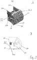
- Fig. 2 includes 2A to 2D and illustrates a specific embodiment of a device according to the first aspect.
- Figure 2A shows a perspective view while 2B to 2D Show side views of the device from different directions.
- Fig. 2 shows a device 20 for adjusting the irradiance of light which has been emitted by a radiation source 21.
- the device 20 has a neutral density filter 22, which can be pivoted in front of the beam outlet opening of the radiation source 21, the beam outlet opening of the radiation source 21 being shown in the illustration of FIG 2A and 2B located below. In the position shown, the neutral density filter 22 is not in the beam path of the radiation emitted by the light source, so that it is not filtered and its irradiance is not reduced.
- the device 20 of the Fig. 2 also has a first filter frame 24 to which the neutral density filter 22 is attached.
- the first filter frame 24 is shaped in such a way that the neutral density filter 22, which is flat in the initial state, adjoins the first filter frame 24 in this way can attach that it is arranged in the attached state along a portion of a cylindrical surface.
- the first filter frame 24 is shaped in such a way that it has a linkage which surrounds a cylinder segment, holding tabs 24.1 being arranged on the two opposite curved ends of the cylinder segment, which are used to fasten the neutral density filter 22.
- the cylinder segment can extend over a circular arc section in a range from 110 ° to 130 °, in particular approximately 120 °, so that the light emerging from the beam exit opening is detected in its entire opening angle.
- the first filter frame 24 is also designed such that on the opposite end faces of the cylinder segment surrounded by its linkage, the first filter frame 24 is articulated in the region of the cylinder axis to a fastening wall 230 which is connected to the housing 21.1 of the radiation source 21.
- a second filter frame 25 is attached to the mounting wall 230.
- the second filter frame 25 is constructed in a similar manner to the first filter frame 24 and is only slightly smaller in its spatial dimensions, so that it is arranged within the first filter frame 24 so as to be pivotable about the radiation source 21.
- a second neutral density filter (not shown) can be attached to the second filter frame 25 in the same way as the first neutral density filter 22 to the first filter frame 24.
- the first neutral density filter 22 and the second neutral density filter can be given by woven and possibly blackened stainless steel wires. You can ... a have different tissue densities and thus different degrees of transmission.
- the device 20 according to Fig. 2 furthermore has a first drive unit 26 and a second drive unit 27, the first drive unit 26 being connected to the first filter frame 24 and the second drive unit 27 being connected to the second filter frame 25.
- the two drive units 26 and 27 are located on opposite sides of the housing 21.1 and are each fastened there with suitable fastening means to the respective fastening wall.
- the drive units 26 and 27 can be controlled independently of one another, so that the filter frames 24 and 25 connected to them can correspondingly be pivoted independently of one another.
- the device 20 according to Fig. 2 also has a standard filter frame 28 attached to the beam exit opening. This can serve to accommodate additional filters 29. These can be spectral filters, for example, with which an adaptation of the emission spectrum of the light source to the solar spectrum can be achieved.
- the device 20 furthermore has fastening brackets 210 and 220, which are connected to the fastening walls 230 on opposite sides.
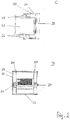
- FIG. 3 points the Figures 3A to 3C and shows views of further technical details of the device 20 according to FIG Fig. 2 .
- Figures 3A and 3B show a cross-sectional side view (A) and a perspective view (B) for illustration the connection between a filter frame and a drive unit.
- the first drive unit 26 has a drive holder 26.1, through which the essential parts of the drive unit are held and which is fastened to the fastening wall 230. Otherwise, the first drive unit 26 essentially has a motor 26.2 and a drive shaft 26.3 connected to the motor 26.2.
- the drive shaft 26.3 is connected to two drivers 26.4, between which the first filter frame 24 is fastened. From the outside, a cylindrical pin 26.5 is guided through corresponding openings in the drivers 26.4 and the first filter frame 24, and all the parts mentioned are connected to the drive shaft 26.3 by means of a screw 26.6.
- Figure 3C shows further details of the connection between the first filter frame 24 and the drive unit 26.
- the drive of the first filter frame 24 takes place by means of a positive connection of the drive shaft 26.3 with the pin 26.5 and a positive connection of the pin 265 with the first filter frame 24.
- the drive shaft 26.3 and the pin 26.5 is positively connected to one another and secondly the first filter frame 24 and the pin 26.5 are positively connected to one another.
- the drive shaft 26.3 has a drive shaft positive locking element 26.31 and the pin has a first pin positive locking element 26.51 and the positive locking elements 26.31 and 26.51 interlock.
- the first filter frame 24 has a filter frame interlocking element 24.2 and the pin 26.5 has a second pin interlocking element 26.52 and the interlocking elements 24.2 and 26.52 also interlock.
- the pin 26.5 also has a sliding surface 26.53 for the mounting of the second filter frame (not shown). This is on the opposite side of the housing driven by the other drive unit 27 in the same way as the first filter frame 24 and slides freely on the sliding surface 26.53.
- the first filter frame 24 slides on a sliding surface of a corresponding pin on the opposite side of the housing.
- each of the two filter frames 24 and 25 is firmly connected to one of the drive units 26 and 27 by means of one of their end sections on one side of the device 20, while the respectively opposite section of the filter frames 24 and 25 slidably on the sliding surface of the respective pin is stored.
- the device 20 according to Fig. 2 furthermore has side walls 230 and 240 which are connected to the housing 21.1 on opposite sides thereof.
- the drive units 26 and 27 are each connected to one of the side walls 230 and 240.
- Fig. 4 points Figures 4A to 4D and shows different positions of the two neutral density filters in a device according to Fig. 2 .
- Each of the states shown is shown both in a side view and in a perspective view from below. It is assumed that the first, outer filter frame 24 contains a first neutral density filter 22 with a transmittance of 30% and that the second, inner filter frame 25 contains a second neutral density filter with a transmittance of 50%.
- Figure 4A shows a state in which both filter frames 24 and 25 are swung out, accordingly none of the neutral density filters in the beam path of the emerging Light radiation is located. The irradiance is thus 100% of the light output emitted by the light source.
- Figure 4B shows a state in which the first, outer filter frame 24 is pivoted in front of the light exit opening.
- the irradiance is 70% of the emitted radiation power.
- Figure 4C shows a state in which the second filter frame 25 with the second neutral density filter 23 is pivoted in front of the outlet opening.
- the irradiance is 50% of the emitted light output.
- Figure 4D finally shows a state in which both filter frames 24 and 25 are pivoted in front of the beam outlet opening.
- the irradiance is 15% of the light output originally emitted by the light source.
- a device such as that according to Fig. 2 is ideally suited for use in a sun simulator, in which, by means of the described change in the positions of the neutral density filters, for example a daylight curve with changing sun positions and thus changing sunlight intensity can be mapped very well.
- a computer program product is designed to control a device according to the first aspect.
- the computer program product can be connected to the drive units and control them in a desired manner and provided by the computer program product.
- the computer program product can include a number of different modes.
- One operating mode can provide that certain irradiance levels, that is to say total transmittances of the neutral density filter, should be set in a predetermined time sequence. In this way, a course of daylight with changing sun positions and irradiance levels can be mapped.
- Another mode of operation can map rapidly changing irradiance levels, such as those that can occur when clouds form or when driving into a tunnel. The latter can optionally also be coupled to a random generator.
- a simple operating mode can provide that a transmittance is entered manually by user input and this is then brought about by appropriate control of the drive units. If the transmittance cannot be set exactly by the existing neutral density filter, this operating mode calculates the filter combination by which the desired transmittance is achieved is approximated as best as possible.
- the computer program product is additionally connected to the light source or to the control device such as the electrical ballast in order to control it, for example to set a specific point within a range between 50 and 100%. In this way, a desired temporal course of the light output can also be generated together with the selection of a specific filter.
- a woven metal or stainless steel wire is used as a neutral density filter in a device for adjusting the irradiance, in particular a device according to the first aspect.
- a device for checking the effect of light radiation on an object at least one device according to the first aspect and a device for receiving an object to be irradiated.
- a device for receiving an object to be irradiated is designed to receive a motor vehicle.
- test bench for motor vehicles can be used in particular for the optimization of air conditioning systems, for example with regard to a fast control with rapidly changing irradiance (cloud simulation and / or tunnel simulation).
- the device for receiving an object to be irradiated is designed to receive a plant growth chamber, in particular in order to investigate the influence of changing irradiance and to present geographic and seasonal daily trends.
- the device for receiving an object to be irradiated is designed to receive components or vehicles for military applications in order to simulate the influence of the daily solar thermal load.
- the device for receiving an object to be irradiated is designed to receive assemblies from the construction industry, aircraft construction, sensors or photovoltaics, in particular in order to evaluate the influence of thermal gradients arising from changing irradiance.
- the device for receiving an object to be irradiated is designed to receive electronic components or electronic components or control cabinets, in particular in order to check the influence of the daily solar thermal load.
Description
Die vorliegende Offenbarung bezieht sich auf eine Vorrichtung zur Anpassung der Bestrahlungsstärke von Licht, welches von einer Strahlungsquelle emittiert worden ist, die Verwendung eines gewebten Metall- oder Edelstrahldrahts als Neutraldichtefilter in einer Vorrichtung zur Anpassung der Bestrahlungsstärke und auf den Einsatz einer derartigen Vorrichtung in einer Vorrichtung zur Prüfung der Auswirkung von Lichtstrahlung auf ein Objekt.The present disclosure relates to a device for adjusting the irradiance of light emitted by a radiation source, the use of a woven metal or noble beam wire as a neutral density filter in a device for adjusting the irradiance and the use of such a device in a device to check the effect of light radiation on an object.
Es sind seit geraumer Zeit Vorrichtungen zur Simulation von Sonnenlicht, auch Sonnensimulatoren genannt, bekannt. Ein Sonnensimulator kann dazu dienen, die Auswirkungen des Sonnenlichts auf bestimmte zu bestrahlende Objekte unter Laborbedingungen zu untersuchen. Da natürliches Sonnenlicht starken zeitlichen Schwankungen unterliegt, hat der Einsatz eines Sonnensimulators gegenüber Freilandversuchen den Vorteil, dass Messungen unter definierten, kontinuierlichen, tages- und jahreszeitlich unabhängigen Bedingungen durchgeführt und auch reproduziert werden können.Devices for simulating sunlight, also called sun simulators, have been known for some time. A sun simulator can be used to study the effects of sunlight on certain objects to be irradiated under laboratory conditions. Since natural sunlight is subject to strong fluctuations in time, the use of a sun simulator compared to field trials has the advantage that measurements can be carried out and also reproduced under defined, continuous, day and season-independent conditions.
Es ist beispielsweise bekannt, dass Sonnenlicht polymere Materialien schädigen kann. In der Regel leitet es den Abbauprozeß ein, der sich in Wechselwirkung mit Temperatur, Feuchte und weiteren Einflüssen beschleunigen kann. Ebenso wichtig ist es, die Effekte des Wärmeeintrags über die Sonne auf Baugruppen sowie letztlich auf das komplette Produkt zu verstehen. Hier werden wichtige Erkenntnisse zur Betriebsfähigkeit unter Wärmelast gewonnen und das Temperaturmanagement und die Produktstabilität überprüft.For example, it is known that sunlight can damage polymeric materials. As a rule, it initiates the degradation process, which can accelerate in interaction with temperature, humidity and other influences. It is equally important to understand the effects of heat input from the sun on assemblies and ultimately on the entire product. Here are important findings on operability obtained under heat load and the temperature management and product stability checked.
Die Anwendungs- und Einsatzmöglichkeiten von Sonnensimulatoren reichen von kleinen Labor- und Walk-In-Kammern für Komponenten- oder Baugruppenprüfung, über Drive-In-Kammern für komplette Fahrzeuge bis hin zu Hallen-Großanlagen für LKWs, Züge oder Flugzeuge. Daneben ist eine möglichst hohe spektrale Übereinstimmung der künstlichen Lichtquelle mit dem natürlichen Sonnenlicht entscheidend für die Güte der zu simulierenden Testbedingungen und ihrer verläßlichen Wiederholbarkeit. Im Falle von Abweichungen können spektrale optische Filter eingesetzt werden, um das Spektrum demjenigen des Sonnenlichts anzupassen.The application and application options for sun simulators range from small laboratory and walk-in chambers for component or assembly testing, through drive-in chambers for complete vehicles to large hall systems for trucks, trains or airplanes. In addition, the highest possible spectral correspondence of the artificial light source with the natural sunlight is crucial for the quality of the test conditions to be simulated and their reliable repeatability. In the event of deviations, spectral optical filters can be used to match the spectrum to that of sunlight.
Erfindungsgemäß umfasst eine Vorrichtung zur Anpassung der Bestrahlungsstärke eine Strahlungsquelle und mindestens ein vor der Strahlungsquelle bewegbar angeordnetes Neutraldichtefilter, wobei das Neutraldichtefilter in den Strahlengang der Strahlungsquelle oder aus dem Strahlengang der Strahlungsquelle bewegt werden kann, und wobei die Vorrichtung die Merkmale gemäß dem Anspruch 1 umfasst.According to the invention, a device for adapting the irradiance comprises a radiation source and at least one neutral density filter movably arranged in front of the radiation source, the neutral density filter being able to be moved into the beam path of the radiation source or out of the beam path of the radiation source, and the device comprising the features according to claim 1.
Nach einem zweiten Aspekt der Offenbarung ist ein Computerprogrammprodukt dafür ausgelegt, eine Vorrichtung gemäß dem ersten Aspekt anzusteuern.According to a second aspect of the disclosure, a computer program product is designed to control a device according to the first aspect.
Nach einem dritten Aspekt der Offenbarung wird ein gewebter Metall- oder Edelstahldraht als Neutraldichtefilter in einer Vorrichtung zur Anpassung der Bestrahlungsstärke verwendet.According to a third aspect of the disclosure, a woven metal or stainless steel wire is used as a neutral density filter in a device for adjusting the irradiance.
Nach einem vierten Aspekt der Offenbarung umfasst eine Vorrichtung zur Prüfung der Auswirkung von Lichtstrahlung auf ein Objekt mindestens eine Vorrichtung nach dem ersten Aspekt und eine Einrichtung zur Aufnahme eines zu bestrahlenden Objekts.According to a fourth aspect of the disclosure, a device for checking the effect of light radiation on an object comprises at least one device according to the first aspect and a device for receiving an object to be irradiated.
Der Fachmann erkennt zusätzliche Merkmale und Vorteile beim Lesen der nachfolgenden ausführlichen Beschreibung und der beiliegenden Zeichnungen.Those skilled in the art will recognize additional features and advantages upon reading the following detailed description and the accompanying drawings.
Die beiliegenden Zeichnungen stellen Ausführungsbeispiele dar und dienen zusammen mit der Beschreibung zum Erläutern von Prinzipien der vorliegenden Offenbarung sowie Einzelheiten der Ausführungsbeispiele.
-
Fig. 1 zeigt eine schematische Querschnittsseitenansicht einer Vorrichtung zur Anpassung der Bestrahlungsstärke, welche das grundlegende Prinzip der vorliegenden Offenbarung illustriert. -
Fig. 2 umfasstFig. 2A bis 2D und zeigt verschiedene Ansichten einer Vorrichtung zur Anpassung der Bestrahlungsstärke gemäß einem Ausführungsbeispiel, bei welchem die Vorrichtung zwei jeweils in Filterrahmen befestigte und um die Strahlungsquelle verschwenkbare Neutraldichtefilter aufweist. -
Fig. 3 umfasstFig. 3A bis 3C und zeigt Ansichten technischer Details zur Realisierung einer Vorrichtung gemäßFig. 2 gemäß einem Ausführungsbeispiel. -
Fig. 4 umfasstFig. 4A bis 4D und zeigt jeweils zwei verschiedene Ansichten einer Vorrichtung gemäßFig. 2 bei verschiedenen Stellungen der beiden Neutraldichtefilter gemäß einem Ausführungsbeispiel.
-
Fig. 1 FIG. 12 shows a schematic cross-sectional side view of an apparatus for adjusting the irradiance, which illustrates the basic principle of the present disclosure. -
Fig. 2 includes2A to 2D and shows various views of a device for adjusting the irradiance according to an exemplary embodiment, in which the device has two neutral density filters, each of which is fastened in filter frames and can be pivoted about the radiation source. -
Fig. 3 includes3A to 3C and shows views of technical details for realizing a device according toFig. 2 according to an embodiment. -
Fig. 4 includes4A to 4D and each shows two different views of a device according toFig. 2 at different positions of the two neutral density filters according to one embodiment.
In der folgenden ausführlichen Beschreibung wird auf die beigefügten Zeichnungen Bezug genommen, die Teil dieser bilden und in denen zur Veranschaulichung spezifische Ausführungsbeispiele gezeigt sind, in denen die vorliegende Offenbarung ausgeübt werden kann. In dieser Hinsicht wird Richtungsterminologie wie etwa "oben", "unten", "vorne", "hinten", "vorderes", "hinteres", usw. mit Bezug auf die Orientierung der beschriebenen Figur(en) verwendet. Da Komponenten von Ausführungsbeispielen der vorliegenden Offenbarung in einer Anzahl verschiedener Orientierungen positioniert werden können, dient die Richtungsterminologie zur Veranschaulichung und ist auf keinerlei Weise einschränkend. Es versteht sich, dass andere Ausführungsbeispiele benutzt und strukturelle oder logische Änderungen vorgenommen werden können, ohne von dem Schutzumfang der vorliegenden Offenbarung abzuweichen. Die folgende ausführliche Beschreibung ist deshalb nicht in einschränkendem Sinne aufzufassen und der Schutzumfang der vorliegenden Offenbarung wird durch die angefügten Ansprüche definiert.In the following detailed description, reference is made to the accompanying drawings, which form a part hereof, and in which, by way of illustration, specific exemplary embodiments are shown in which the present disclosure can be made. In this regard, directional terminology such as "top", "bottom", "front", "back", "front", "back", etc. is used with reference to the orientation of the figure (s) described. Because components of embodiments of the present disclosure can be positioned in a number of different orientations, the directional terminology is illustrative and is in no way limiting. It is understood that other embodiments may be used and structural or logical changes may be made without departing from the scope of the present disclosure. The following detailed description, therefore, is not to be taken in a limiting sense, and the scope of the present disclosure is defined by the appended claims.
Im Folgenden werden Ausführungsbeispiele für bestimmte Ausgestaltungen und Weiterbildungen der Vorrichtung gemäß dem ersten Aspekt anhand bestimmter Merkmale vorgestellt. Diese Merkmale können einzeln oder in Kombination miteinander zur Anwendung kommen. Einige dieser Merkmale sind in den in den
Gemäß einem Ausführungsbeispiel der Vorrichtung 10 nach dem ersten Aspekt weist diese mindestens ein weiteres Neutraldichtefilter 13 (gestrichelt) auf. Dieses kann in ebensolcher Weise wie das Neutraldichtefilter 12 in oder aus dem Strahlengang der Strahlungsquelle 11, insbesondere unabhängig von dem Neutraldichtefilter 12, bewegbar angeordnet sein, wie durch einen weiteren Doppelpfeil angedeutet ist. Dabei ist das weitere Neutraldichtefilter 13 im Strahlengang an einer anderen Position als das Neutraldichtefilter 12 positionierbar, so dass die beiden Neutraldichtefilter 12 und 13 im Strahlengang hintereinander angeordnet werden können. Die Neutraldichtefilter 12 und 13 können gleiche oder verschiedene Dichtegrade und somit Transmissionsgrade aufweisen, wobei sich im letzteren Fall je nach Position der Neutraldichtefilter 12 und 13 im Strahlengang oder außerhalb davon vier verschiedene Beträge der Bestrahlungsstärke im Strahlengang hinter den Neutraldichtefiltern 12 und 13 einstellen lassen können.According to an embodiment of the
Gemäß einem Ausführungsbeispiel der Vorrichtung 10 nach dem ersten Aspekt weist die Strahlungsquelle 11 ein Gehäuse 11.1 und eine in dem Gehäuse 11.1 befestigte Lichtquelle 11.2 auf. Gemäß einem weiteren Ausführungsbeispiel ist die Lichtquelle 11.2 derart beschaffen, dass sie ein Spektrum aussendet, welches das Sonnenspektrum möglichst weitgehend approximiert. Gemäß einem weiteren Beispiel können in dem oder außerhalb des Gehäuses 11.1 geeignete optische Filter angeordnet werden, um die Approximation des Spektrums an das Sonnenspektrum weiter zu verbessern. Gemäß einem weiteren Ausführungsbeispiel kann die Lichtquelle 11.2 durch eine Metallhalogenidlampe gegeben sein. Gemäß einem weiteren Ausführungsbeispiel kann die Lichtquelle 11.2 durch eine Xenonlampe gegeben sein.According to an embodiment of the
Gemäß einem Ausführungsbeispiel der Vorrichtung 10 nach dem ersten Aspekt weist das mindestens eine Neutraldichtefilter 12 einen gewebten Metall- oder Edelstrahldraht auf. Gemäß einem weiteren Ausführungsbeispiel davon kann der Transmissionsgrad eines derartigen Neutraldichtefilters über die Dichte des Gewebes eingestellt werden. Gemäß einem weiteren Ausführungsbeispiel kann der gewebte Metall- oder Edelstrahldraht geschwärzt sein.According to an embodiment of the
Gemäß einem Ausführungsbeispiel der Vorrichtung 10 nach dem ersten Aspekt weist das mindestens eine Neutraldichtefilter 12 eine Lochfolie oder ein Lochblech auf. Gemäß einem weiteren Ausführungsbeispiel davon kann der Transmissionsgrad eines derartigen Neutraldichtefilters im Falle von äquidistant gelochten Folien oder Blechen durch die Größe der Löcher bzw. das Verhältnis Lochfläche zu Gesamtfläche eingestellt werden. Gemäß einem weiteren Ausführungsbeispiel davon kann die Folie oder das Blech geschwärzt sein.According to an embodiment of the
Gemäß weiteren Ausführungsbeispielen der Vorrichtung 10 nach dem ersten Aspekt kann das mindestens eine Neutraldichtefilter 12 auch durch Neutral- oder Graugläser oder Neutralreflexionsfilter gegeben sein.According to further exemplary embodiments of the
Gemäß einem Ausführungsbeispiel der Vorrichtung 10 nach dem ersten Aspekt ist die Lichtleistung der Lichtquelle 11.2 regelbar oder dimmbar. Gemäß einem weiteren Ausführungsbeispiel davon ist die Lichtleistung mittels eines Steuergeräts wie eines elektrischen Vorschaltgeräts regelbar.According to an embodiment of the
Erfindungsgemäß ist das mindestens eine Neutraldichtefilter 12 entlang einer gewölbten Fläche angeordnet. Erfindungsgemäß ist das mindestens eine Neutraldichtefilter 12 entlang eines Abschnitts einer zylindrischen Fläche angeordnet, wobei es entlang der zylindrischen Fläche bewegbar ist.According to the invention, the at least one
Gemäß einem Ausführungsbeispiel der Vorrichtung 10 nach dem ersten Aspekt ist das mindestens eine Neutraldichtefilter 12 durch eine mechanische Verstellvorrichtung bewegbar. Gemäß einem weiteren Ausführungsbeispiel davon ist die mechanische Verstellvorrichtung mit dem Gehäuse 11.1 der Strahlungsquelle 11 verbunden, insbesondere direkt mit dem Gehäuse 11.1 der Strahlungsquelle 11 verbunden.According to an embodiment of the
Erfindungsgemäß ist das mindestens eine Neutraldichtefilter 12 um die Strahlungsquelle 11 verschwenkbar angeordnet. Erfindungsgemäß ist die Anordnung derart, dass das Neutraldichtefilter 12 auf einer Kreisbahn um die in einem Zentrum liegende Lichtquelle 11.2 verschwenkbar ist. Erfindungsgemäß sind zwei Neutraldichtefilter jeweils auf einer Kreisbahn um die im Zentrum liegende Lichtquelle verschwenkbar, wobei die Kreisbahnen unterschiedliche Radien aufweisen, so dass die Neutraldichtefilter sich auf verschiedenen Bahnen bewegen und sich somit bei ihrer Bewegung gegenseitig nicht stören.According to the invention, the at least one
Gemäß einem Ausführungsbeispiel der Vorrichtung 10 nach dem ersten Aspekt weist diese ferner mindestens einen Filterrahmen auf, in welchem das mindestens eine Neutraldichtefilter 12 befestigbar ist, wobei in einem derartigen Filterrahmen ein oder mehrere Neutraldichtefilter befestigbar sind. Gemäß einem Ausführungsbeispiel davon weist die Vorrichtung 10 eine Mehrzahl derartiger Filterrahmen auf, welche unabhängig voneinander bewegbar sind.According to an embodiment of the
Gemäß einem Ausführungsbeispiel einer Vorrichtung 10 nach dem ersten Aspekt weist diese ferner eine Antriebseinheit, insbesondere einen Motor, auf, welcher mit dem mindestens einen Neutraldichtefilter 12 verbunden ist, um dieses in Bewegung zu setzen. Im Falle des Vorhandenseins eines Filterrahmens für die Aufnahme des mindestens einen Neutraldichtefilters 12 kann die Antriebseinheit mit dem Filterrahmen verbunden sein. Gemäß einem weiteren Ausführungsbeispiel davon weist die Vorrichtung 10 ferner ein Computerprogramm auf, welches konfiguriert ist, die Antriebseinheit in einer gewünschten Weise anzutreiben. Ein derartiges Computerprogramm kann beispielsweise dafür ausgelegt sein, bei Anwendung der Vorrichtung auf einen Sonnensimulator einen Tagesverlauf der Bestrahlungsstärke der Sonnenstrahlung durch geeigneten Einsatz und Steuerung von zwei oder mehr Neutraldichtefiltern nachzubilden.According to an exemplary embodiment of a
Die Vorrichtung 20 der
Der erste Filterrahmen 24 ist ferner so beschaffen, dass an den gegenüberliegenden Stirnseiten des von seinem Gestänge umrandeten Zylindersegments der erste Filterrahmen 24 im Bereich der Zylinderachse an eine Befestigungswand 230 angelenkt ist, welche mit dem Gehäuse 21.1 der Strahlungsquelle 21 verbunden ist. In ebensolcher Weise ist ein zweiter Filterrahmen 25 an der Befestigungswand 230 befestigt. Der zweite Filterrahmen 25 ist auf ähnliche Weise aufgebaut wie der erste Filterrahmen 24 und lediglich in seinen räumlichen Dimensionen geringfügig kleiner, so dass er innerhalb des ersten Filterrahmens 24 verschwenkbar um die Strahlungsquelle 21 angeordnet ist. An dem zweiten Filterrahmen 25 kann ein zweites Neutraldichtefilter (nicht gezeigt) auf die gleiche Weise befestigt werden, wie das erste Neutraldichtefilter 22 an den ersten Filterrahmen 24.The
Das erste Neutraldichtefilter 22 und das zweite Neutraldichtefilter können durch gewebte und gegebenenfalls geschwärzte Edelstahldrähte gegeben sein. Sie können eine voneinander verschiedene Gewebedichte und somit verschiedene Transmissionsgrade aufweisen.The first
Die Vorrichtung 20 gemäß
Die Vorrichtung 20 gemäß
Die Vorrichtung 20 weist des Weiteren Befestigungswinkel 210 und 220 auf, welche an gegenüberliegenden Seiten mit den Befestigungswänden 230 verbunden sind.The
Auf diese Art und Weise ist jede der beiden Filterrahmen 24 und 25 mittels einer ihrer stirnseitigen Abschnitte auf jeweils einer Seite der Vorrichtung 20 mit einer der Antriebseinheiten 26 und 27 fest verbunden, während der jeweils gegenüberliegende Abschnitt der Filterrahmen 24 und 25 gleitend auf der Gleitfläche des jeweiligen Zapfens gelagert ist.In this way, each of the two filter frames 24 and 25 is firmly connected to one of the
Die Vorrichtung 20 gemäß
Wie bereits weiter oben erwähnt, kann die Lichtleistung der Lichtquelle 11.2 regelbar sin. Beispielsweise kann mittels eines elektrischen Vorschaltgeräts die Lichtleistung zwischen 50% und 100% regelbar sein. Somit ergeben sich in dieser Konstellation für den Einsatz der obigen Filter die folgenden Regelbereiche:
- Ohne Filter: 50-100%
- Mit 30% Filter: 35-70%
- Mit 50% Filter: 25-50%
- Beide Filter: 10-20%
- Without filter: 50-100%
- With 30% filter: 35-70%
- With 50% filter: 25-50%
- Both filters: 10-20%
Aus dem Vorangegangenen wird deutlich, dass eine Vorrichtung wie eine solche gemäß
Gemäß einem zweiten Aspekt der Offenbarung ist ein Computerprogrammprodukt dafür ausgelegt, eine Vorrichtung gemäß dem ersten Aspekt anzusteuern. Gemäß einem Ausführungsbeispiel davon kann das Computerprogrammprodukt mit den Antriebseinheiten verbunden sein und diese auf eine gewünschte und durch das Computerprogrammprodukt vorgesehene Art und Weise ansteuern. Das Computerprogrammprodukt kann eine Anzahl verschiedener Betriebsarten enthalten. Eine Betriebsart kann vorsehen, dass in einer vorgegebenen zeitlichen Abfolge bestimmte Bestrahlungsstärken, also Gesamt-Transmissionsgrade der Neutraldichtefilter, eingestellt werden sollen. Auf diese Weise kann ein Tageslichtverlauf mit sich verändernden Sonnenständen und Bestrahlungsstärken abgebildet werden. Eine andere Betriebsart kann schnell ändernde Bestrahlungsstärken abbilden, wie sie etwa bei Wolkenbildung oder bei Fahrt in einen Tunnel auftreten können. Letzteres kann gegebenenfalls zusätzlich mit einem Zufallsgenerator gekoppelt sein. Beide beschriebene Betriebsarten können auch miteinander kombiniert werden. Eine einfache Betriebsart kann vorsehen, dass manuell durch Benutzereingabe ein Transmissionsgrad eingegeben wird und dieser dann durch entsprechende Ansteuerung der Antriebseinheiten herbeigeführt wird. Sollte der Transmissionsgrad durch die vorhandenen Neutraldichtefilter nicht exakt eingestellt werden können, so berechnet diese Betriebsart diejenige Filterkombination, durch die der gewünschte Transmissionsgrad bestmöglich approximiert wird. Gemäß einem weiteren Ausführungsbeispiel ist das Computerprogrammprodukt zusätzlich mit der Lichtquelle bzw. dem Steuergerät wie dem elektrischen Vorschaltgerät verbunden, um dieses zu steuern, etwa um innerhalb eines Bereichs zwischen 50 und 100% einen bestimmten Punkt einzustellen. Auf diese Weise kann auch ein gewünschter zeitlicher Verlauf der Lichtleistung zusammen mit der Auswahl eines bestimmten Filters erzeugt werden.According to a second aspect of the disclosure, a computer program product is designed to control a device according to the first aspect. According to one exemplary embodiment thereof, the computer program product can be connected to the drive units and control them in a desired manner and provided by the computer program product. The computer program product can include a number of different modes. One operating mode can provide that certain irradiance levels, that is to say total transmittances of the neutral density filter, should be set in a predetermined time sequence. In this way, a course of daylight with changing sun positions and irradiance levels can be mapped. Another mode of operation can map rapidly changing irradiance levels, such as those that can occur when clouds form or when driving into a tunnel. The latter can optionally also be coupled to a random generator. Both operating modes described can also be combined with one another. A simple operating mode can provide that a transmittance is entered manually by user input and this is then brought about by appropriate control of the drive units. If the transmittance cannot be set exactly by the existing neutral density filter, this operating mode calculates the filter combination by which the desired transmittance is achieved is approximated as best as possible. According to a further exemplary embodiment, the computer program product is additionally connected to the light source or to the control device such as the electrical ballast in order to control it, for example to set a specific point within a range between 50 and 100%. In this way, a desired temporal course of the light output can also be generated together with the selection of a specific filter.
Weitere Ausführungsbeispiele dieses zweiten Aspekts können sich durch Kombination mit weiteren Merkmalen ergeben, wie sie weiter oben im Zusammenhang mit dem ersten Aspekt oder weiter unten im Zusammenhang mit dem vierten Aspekt beschrieben wurden.Further exemplary embodiments of this second aspect can result from a combination with further features, as described above in connection with the first aspect or below in connection with the fourth aspect.
Gemäß einem dritten Aspekt der vorliegenden Offenbarung wird ein gewebter Metall- oder Edelstahldraht als Neutraldichtefilter in einer Vorrichtung zur Anpassung der Bestrahlungsstärke, insbesondere einer Vorrichtung gemäß dem ersten Aspekt, verwendet.According to a third aspect of the present disclosure, a woven metal or stainless steel wire is used as a neutral density filter in a device for adjusting the irradiance, in particular a device according to the first aspect.
Weitere Ausführungsbeispiele dieses dritten Aspekts können sich durch Kombination mit weiteren Merkmalen ergeben, wie sie weiter oben im Zusammenhang mit dem ersten Aspekt oder weiter unten im Zusammenhang mit dem vierten Aspekt beschrieben wurden.Further exemplary embodiments of this third aspect can result from a combination with further features as described above in connection with the first aspect or further below in connection with the fourth aspect.
Weitere Ausführungsbeispiele dieses dritten Aspekts können sich außerdem aus der Wahl anderer oben genannter Filtertypen für das Neutraldichtefilter ergeben.Further exemplary embodiments of this third aspect can also result from the selection of other filter types mentioned above for the neutral density filter.
Gemäß einem vierten Aspekt weist eine Vorrichtung zur Prüfung der Auswirkung von Lichtstrahlung auf ein Objekt mindestens eine Vorrichtung nach dem ersten Aspekt und eine Einrichtung zur Aufnahme eines zu bestrahlenden Objekts auf.According to a fourth aspect, a device for checking the effect of light radiation on an object at least one device according to the first aspect and a device for receiving an object to be irradiated.
Gemäß einem Ausführungsbeispiel des vierten Aspekts ist eine Einrichtung zur Aufnahme eines zu bestrahlenden Objekts dafür ausgelegt ein Kraftfahrzeug aufzunehmen.According to an exemplary embodiment of the fourth aspect, a device for receiving an object to be irradiated is designed to receive a motor vehicle.
Ein derartiger Prüfstand für Kraftfahrzeuge kann insbesondere zur Optimierung von Klimaanlagen, beispielsweise hinsichtlich einer schnellen Regelung bei schnell wechselnder Bestrahlungsstärke (Wolkensimulation und/oder Tunnelsimulation) verwendet werden.Such a test bench for motor vehicles can be used in particular for the optimization of air conditioning systems, for example with regard to a fast control with rapidly changing irradiance (cloud simulation and / or tunnel simulation).
Gemäß einem Beispiel einer Vorrichtung nach dem vierten Aspekt ist die Einrichtung zur Aufnahme eines zu bestrahlenden Objekts dafür ausgelegt, eine Pflanzenwuchskammer aufzunehmen, insbesondere um den Einfluß wechselnder Bestrahlungsstärke zu untersuchen und geographische und saisonale Tagesgänge darzustellen.According to an example of a device according to the fourth aspect, the device for receiving an object to be irradiated is designed to receive a plant growth chamber, in particular in order to investigate the influence of changing irradiance and to present geographic and seasonal daily trends.
Gemäß einem Ausführungsbeispiel einer Vorrichtung nach dem vierten Aspekt ist die Einrichtung zur Aufnahme eines zu bestrahlenden Objekts dafür ausgelegt, Bauteile oder Fahrzeuge für militärische Anwendungen aufzunehmen, um den Einfluß der tagesabhängigen solaren Wärmelast zu simulieren.According to an embodiment of a device according to the fourth aspect, the device for receiving an object to be irradiated is designed to receive components or vehicles for military applications in order to simulate the influence of the daily solar thermal load.
Gemäß einem Ausführungsbeispiel einer Vorrichtung nach dem vierten Aspekt ist die Einrichtung zur Aufnahme eines zu bestrahlenden Objekts dafür ausgelegt, Baugruppen aus der Bauindustrie, dem Flugzeugbau, der Sensorik oder der Photovoltaik aufzunehmen, insbesondere um den Einfluß von durch wechselnde Bestrahlungsstärke entstehenden Wärmegradienten zu bewerten.According to an embodiment of a device according to the fourth aspect, the device for receiving an object to be irradiated is designed to receive assemblies from the construction industry, aircraft construction, sensors or photovoltaics, in particular in order to evaluate the influence of thermal gradients arising from changing irradiance.
Gemäß einem Ausführungsbeispiel einer Vorrichtung nach dem vierten Aspekt ist die Einrichtung zur Aufnahme eines zu bestrahlenden Objekts dafür ausgelegt, elektronische Bauteile oder elektronische Komponenten oder Schaltschränke aufzunehmen, insbesondere um den Einfluß der tagesabhängigen solaren Wärmelast zu prüfen.According to an exemplary embodiment of a device according to the fourth aspect, the device for receiving an object to be irradiated is designed to receive electronic components or electronic components or control cabinets, in particular in order to check the influence of the daily solar thermal load.
Weitere Beispiele einer Vorrichtung nach dem vierten Aspekt können sich durch Kombination mit Merkmalen, wie sie weiter oben im Zusammenhang mit dem ersten Aspekt, dem zweiten Aspekt oder dem dritten Aspekt genannt wurden, ergeben.Further examples of a device according to the fourth aspect can be obtained by combination with features as mentioned above in connection with the first aspect, the second aspect or the third aspect.
Obwohl spezifische Ausführungsformen in dieser Beschreibung dargestellt und beschrieben wurden, ist für den Fachmann auf dem Gebiet zu erkennen, dass die gezeigten und beschriebenen spezifischen Ausführungsformen gegen eine Vielfalt von alternativen und/oder äquivalenten Implementierungen ausgetauscht werden können, ohne vom Schutzbereich der vorliegenden Erfindung abzuweichen. Diese Anmeldung soll jegliche Anpassungen oder Veränderungen der hierin erörterten spezifischen Ausführungsformen abdecken. Daher ist vorgesehen, dass diese Erfindung nur durch die Ansprüche und deren Äquivalente begrenzt ist.Although specific embodiments have been shown and described in this description, it will be apparent to those skilled in the art that the specific embodiments shown and described can be substituted for a variety of alternative and / or equivalent implementations without departing from the scope of the present invention. This application is intended to cover any adaptations or changes to the specific embodiments discussed herein. Therefore, it is intended that this invention be limited only by the claims and their equivalents.
Claims (5)
- Device (20) for adjusting the irradiance, witha radiation source (21); andtwo neutral density filters (22, 23) movably arranged in front of the radiation source (21), wherein the neutral density filters can be moved into the beam path of the radiation source or out of the beam path of the radiation source and can be arranged one behind the other in the beam path of the radiation (14) emitted by the radiation source,characterized in that
both neutral density filters (22, 23) each extend over a segment of one of two cylindrical surfaces spaced at different radii from a common cylinder axis on which the radiation source (21) is located, wherein
both neutral density filters (22, 23) are each pivotable along the respective cylindrical surface independently of one another around the radiation source (21). - Device (20) according to claim 1, in which
both neutral density filters (22, 23) each have a woven metal or stainless steel wire. - Device (20) according to one of the preceding claims, in which
the two neutral density filters (22, 23) have different density factors from each other. - Device (20) according to one of the preceding claims, further comprising
two filter frames (24; 25) in which the two neutral density filters (22; 23) can be mounted, wherein one or more neutral density filters can be mounted in a filter frame. - Device (20) according to one of the preceding claims, further comprising
two drive units (26, 27) connected to the two neutral density filters (22, 23) to set them in motion.
Priority Applications (3)
| Application Number | Priority Date | Filing Date | Title |
|---|---|---|---|
| EP17163613.7A EP3382271B1 (en) | 2017-03-29 | 2017-03-29 | Device for adapting the intensity of radiation |
| CN201810262283.5A CN108692758A (en) | 2017-03-29 | 2018-03-28 | Irradiation level intensity adjustment device |
| US15/939,900 US10627333B2 (en) | 2017-03-29 | 2018-03-29 | Irradiance intensity adjustment device |
Applications Claiming Priority (1)
| Application Number | Priority Date | Filing Date | Title |
|---|---|---|---|
| EP17163613.7A EP3382271B1 (en) | 2017-03-29 | 2017-03-29 | Device for adapting the intensity of radiation |
Publications (2)
| Publication Number | Publication Date |
|---|---|
| EP3382271A1 EP3382271A1 (en) | 2018-10-03 |
| EP3382271B1 true EP3382271B1 (en) | 2020-07-29 |
Family
ID=58464256
Family Applications (1)
| Application Number | Title | Priority Date | Filing Date |
|---|---|---|---|
| EP17163613.7A Active EP3382271B1 (en) | 2017-03-29 | 2017-03-29 | Device for adapting the intensity of radiation |
Country Status (3)
| Country | Link |
|---|---|
| US (1) | US10627333B2 (en) |
| EP (1) | EP3382271B1 (en) |
| CN (1) | CN108692758A (en) |
Families Citing this family (4)
| Publication number | Priority date | Publication date | Assignee | Title |
|---|---|---|---|---|
| DE202018104615U1 (en) * | 2018-08-10 | 2019-11-14 | Zumtobel Lighting Gmbh | Luminaire with variable light output |
| CN109990226A (en) * | 2019-04-09 | 2019-07-09 | 西安建筑科技大学 | A kind of adjustable solar simulator system |
| CN111237681B (en) * | 2020-02-25 | 2022-03-29 | 飞率有限公司 | Day-type hybrid ultra-precise artificial sunlight simulation device and simulation method |
| CN111550723A (en) * | 2020-05-14 | 2020-08-18 | 长春理工大学 | Light and small multi-radiation solar simulator for external field |
Citations (3)
| Publication number | Priority date | Publication date | Assignee | Title |
|---|---|---|---|---|
| WO1993024786A1 (en) * | 1992-05-22 | 1993-12-09 | Panavision International, L.P. | System for varying light intensity such as for use in motion picture photography |
| US5282115A (en) * | 1993-01-28 | 1994-01-25 | Tailored Lighting Inc. | Apparatus for producing light distributions |
| US20070253215A1 (en) * | 2006-04-27 | 2007-11-01 | Pentax Corporation | Light source apparatus for endoscope system |
Family Cites Families (8)
| Publication number | Priority date | Publication date | Assignee | Title |
|---|---|---|---|---|
| DE20103645U1 (en) * | 2001-03-02 | 2001-05-23 | Astrium Gmbh | Sun simulator with sliding filter |
| WO2005112737A1 (en) * | 2004-05-24 | 2005-12-01 | Olympus Corporation | Light source device for endoscope |
| JP2007311085A (en) * | 2006-05-16 | 2007-11-29 | National Institute Of Advanced Industrial & Technology | Dummy sunlight irradiation device |
| CN102598295A (en) * | 2009-07-22 | 2012-07-18 | 美国迅力光能公司 | Solar simulator for flexible solar modules |
| WO2011033025A1 (en) * | 2009-09-16 | 2011-03-24 | Oerlikon Solar Ag, Trübbach | Method and arrangement for adjusting a solar simulator |
| US8797058B2 (en) * | 2011-03-03 | 2014-08-05 | International Business Machines Corporation | Solar cell characterization system with an automated continuous neutral density filter |
| JP2014216147A (en) * | 2013-04-24 | 2014-11-17 | 共進電機株式会社 | Solar simulator |
| CN203431636U (en) * | 2013-09-27 | 2014-02-12 | 锦州阳光气象科技有限公司 | Matrix type solar simulator |
-
2017
- 2017-03-29 EP EP17163613.7A patent/EP3382271B1/en active Active
-
2018
- 2018-03-28 CN CN201810262283.5A patent/CN108692758A/en active Pending
- 2018-03-29 US US15/939,900 patent/US10627333B2/en active Active
Patent Citations (3)
| Publication number | Priority date | Publication date | Assignee | Title |
|---|---|---|---|---|
| WO1993024786A1 (en) * | 1992-05-22 | 1993-12-09 | Panavision International, L.P. | System for varying light intensity such as for use in motion picture photography |
| US5282115A (en) * | 1993-01-28 | 1994-01-25 | Tailored Lighting Inc. | Apparatus for producing light distributions |
| US20070253215A1 (en) * | 2006-04-27 | 2007-11-01 | Pentax Corporation | Light source apparatus for endoscope system |
Also Published As
| Publication number | Publication date |
|---|---|
| CN108692758A (en) | 2018-10-23 |
| EP3382271A1 (en) | 2018-10-03 |
| US10627333B2 (en) | 2020-04-21 |
| US20180321132A1 (en) | 2018-11-08 |
Similar Documents
| Publication | Publication Date | Title |
|---|---|---|
| EP3382271B1 (en) | Device for adapting the intensity of radiation | |
| EP2885669B1 (en) | Optical arrangement and a microscope | |
| DE102008050851B4 (en) | X-ray analysis instrument with movable aperture window | |
| DE102010009022B4 (en) | Illumination system and projection objective of a mask inspection system | |
| DE102012102651B3 (en) | Test device and test method for a traffic monitoring device with a laser scanner | |
| DE102007018825A1 (en) | Radiating device for simulated solar light | |
| DE102011115141A1 (en) | Solar Simulator | |
| DE102011087955B4 (en) | Scanning electron microscope | |
| DE102015200034A1 (en) | spectrometer | |
| DE3022737C2 (en) | ||
| DE102014009143A1 (en) | Motor vehicle camera device with controllable active lighting | |
| DE202019106995U1 (en) | X-ray collimator with main and secondary examination area | |
| WO2014016103A1 (en) | Method and device for detecting optical signals | |
| DE102018103487B4 (en) | Method for operating a lighting device of a motor vehicle | |
| DE112019006405T5 (en) | PROCEDURE FOR CORRECTING A NON-LINEAR DISTANCE ERROR OF A THREE-DIMENSIONAL DISTANCE MEASURING CAMERA USING PULSE PHASE SHIFT | |
| WO2003046663A2 (en) | Characterization of the illumination angle distribution of a projection lighting system | |
| DE102013227096A1 (en) | solar simulator | |
| DE10225674A1 (en) | Collimation lens system for homogenization of laser beam has two arrays of two-dimensional lenses separated along optical axis and with the second array divided into two sub-arrays | |
| DE3903150C2 (en) | ||
| EP2532947B1 (en) | Test device for measuring the function of a solar module and test vehicle | |
| EP3274962B1 (en) | Method for the reconstruction of a test part in an x-ray ct method in an x-ray ct system by means of an intelligent path curve | |
| DE102014220282A1 (en) | DEVICE AND METHOD FOR MULTIPLE REFILLING OF LIGHT RADIATIONS THROUGH A COMMON FOCUS | |
| EP1524512B1 (en) | Testing device for vehicle lights, in particular for motor vehicles | |
| DE102013212833B4 (en) | Method for obtaining x-ray images and x-ray imaging system | |
| DE2036165C3 (en) | Infrared spectrometer |
Legal Events
| Date | Code | Title | Description |
|---|---|---|---|
| PUAI | Public reference made under article 153(3) epc to a published international application that has entered the european phase |
Free format text: ORIGINAL CODE: 0009012 |
|
| STAA | Information on the status of an ep patent application or granted ep patent |
Free format text: STATUS: REQUEST FOR EXAMINATION WAS MADE |
|
| 17P | Request for examination filed |
Effective date: 20170329 |
|
| AK | Designated contracting states |
Kind code of ref document: A1 Designated state(s): AL AT BE BG CH CY CZ DE DK EE ES FI FR GB GR HR HU IE IS IT LI LT LU LV MC MK MT NL NO PL PT RO RS SE SI SK SM TR |
|
| AX | Request for extension of the european patent |
Extension state: BA ME |
|
| STAA | Information on the status of an ep patent application or granted ep patent |
Free format text: STATUS: EXAMINATION IS IN PROGRESS |
|
| 17Q | First examination report despatched |
Effective date: 20191211 |
|
| RIC1 | Information provided on ipc code assigned before grant |
Ipc: G02B 5/20 20060101ALN20200206BHEP Ipc: F21V 14/08 20060101ALN20200206BHEP Ipc: G01N 17/00 20060101ALI20200206BHEP Ipc: F21V 9/02 20180101AFI20200206BHEP Ipc: G01N 33/00 20060101ALN20200206BHEP Ipc: F21S 8/00 20060101ALI20200206BHEP Ipc: F21V 9/08 20180101ALI20200206BHEP Ipc: G02B 26/02 20060101ALN20200206BHEP |
|
| RIC1 | Information provided on ipc code assigned before grant |
Ipc: G02B 26/02 20060101ALN20200309BHEP Ipc: G01N 33/00 20060101ALN20200309BHEP Ipc: F21S 8/00 20060101ALI20200309BHEP Ipc: F21V 9/02 20180101AFI20200309BHEP Ipc: F21V 14/08 20060101ALN20200309BHEP Ipc: G01N 17/00 20060101ALI20200309BHEP Ipc: G02B 5/20 20060101ALN20200309BHEP Ipc: F21V 9/08 20180101ALI20200309BHEP |
|
| RIC1 | Information provided on ipc code assigned before grant |
Ipc: G01N 33/00 20060101ALN20200323BHEP Ipc: F21S 8/00 20060101ALI20200323BHEP Ipc: G02B 5/20 20060101ALN20200323BHEP Ipc: F21V 9/02 20180101AFI20200323BHEP Ipc: F21V 9/08 20180101ALI20200323BHEP Ipc: G01N 17/00 20060101ALI20200323BHEP Ipc: G02B 26/02 20060101ALN20200323BHEP Ipc: F21V 14/08 20060101ALN20200323BHEP |
|
| GRAP | Despatch of communication of intention to grant a patent |
Free format text: ORIGINAL CODE: EPIDOSNIGR1 |
|
| STAA | Information on the status of an ep patent application or granted ep patent |
Free format text: STATUS: GRANT OF PATENT IS INTENDED |
|
| INTG | Intention to grant announced |
Effective date: 20200519 |
|
| GRAS | Grant fee paid |
Free format text: ORIGINAL CODE: EPIDOSNIGR3 |
|
| GRAA | (expected) grant |
Free format text: ORIGINAL CODE: 0009210 |
|
| STAA | Information on the status of an ep patent application or granted ep patent |
Free format text: STATUS: THE PATENT HAS BEEN GRANTED |
|
| AK | Designated contracting states |
Kind code of ref document: B1 Designated state(s): AL AT BE BG CH CY CZ DE DK EE ES FI FR GB GR HR HU IE IS IT LI LT LU LV MC MK MT NL NO PL PT RO RS SE SI SK SM TR |
|
| REG | Reference to a national code |
Ref country code: CH Ref legal event code: EP |
|
| REG | Reference to a national code |
Ref country code: AT Ref legal event code: REF Ref document number: 1296233 Country of ref document: AT Kind code of ref document: T Effective date: 20200815 |
|
| REG | Reference to a national code |
Ref country code: IE Ref legal event code: FG4D Free format text: LANGUAGE OF EP DOCUMENT: GERMAN |
|
| REG | Reference to a national code |
Ref country code: DE Ref legal event code: R096 Ref document number: 502017006381 Country of ref document: DE |
|
| REG | Reference to a national code |
Ref country code: LT Ref legal event code: MG4D |
|
| REG | Reference to a national code |
Ref country code: NL Ref legal event code: MP Effective date: 20200729 |
|
| PG25 | Lapsed in a contracting state [announced via postgrant information from national office to epo] |
Ref country code: ES Free format text: LAPSE BECAUSE OF FAILURE TO SUBMIT A TRANSLATION OF THE DESCRIPTION OR TO PAY THE FEE WITHIN THE PRESCRIBED TIME-LIMIT Effective date: 20200729 Ref country code: NO Free format text: LAPSE BECAUSE OF FAILURE TO SUBMIT A TRANSLATION OF THE DESCRIPTION OR TO PAY THE FEE WITHIN THE PRESCRIBED TIME-LIMIT Effective date: 20201029 Ref country code: BG Free format text: LAPSE BECAUSE OF FAILURE TO SUBMIT A TRANSLATION OF THE DESCRIPTION OR TO PAY THE FEE WITHIN THE PRESCRIBED TIME-LIMIT Effective date: 20201029 Ref country code: FI Free format text: LAPSE BECAUSE OF FAILURE TO SUBMIT A TRANSLATION OF THE DESCRIPTION OR TO PAY THE FEE WITHIN THE PRESCRIBED TIME-LIMIT Effective date: 20200729 Ref country code: LT Free format text: LAPSE BECAUSE OF FAILURE TO SUBMIT A TRANSLATION OF THE DESCRIPTION OR TO PAY THE FEE WITHIN THE PRESCRIBED TIME-LIMIT Effective date: 20200729 Ref country code: GR Free format text: LAPSE BECAUSE OF FAILURE TO SUBMIT A TRANSLATION OF THE DESCRIPTION OR TO PAY THE FEE WITHIN THE PRESCRIBED TIME-LIMIT Effective date: 20201030 Ref country code: SE Free format text: LAPSE BECAUSE OF FAILURE TO SUBMIT A TRANSLATION OF THE DESCRIPTION OR TO PAY THE FEE WITHIN THE PRESCRIBED TIME-LIMIT Effective date: 20200729 Ref country code: PT Free format text: LAPSE BECAUSE OF FAILURE TO SUBMIT A TRANSLATION OF THE DESCRIPTION OR TO PAY THE FEE WITHIN THE PRESCRIBED TIME-LIMIT Effective date: 20201130 Ref country code: HR Free format text: LAPSE BECAUSE OF FAILURE TO SUBMIT A TRANSLATION OF THE DESCRIPTION OR TO PAY THE FEE WITHIN THE PRESCRIBED TIME-LIMIT Effective date: 20200729 |
|
| PG25 | Lapsed in a contracting state [announced via postgrant information from national office to epo] |
Ref country code: LV Free format text: LAPSE BECAUSE OF FAILURE TO SUBMIT A TRANSLATION OF THE DESCRIPTION OR TO PAY THE FEE WITHIN THE PRESCRIBED TIME-LIMIT Effective date: 20200729 Ref country code: PL Free format text: LAPSE BECAUSE OF FAILURE TO SUBMIT A TRANSLATION OF THE DESCRIPTION OR TO PAY THE FEE WITHIN THE PRESCRIBED TIME-LIMIT Effective date: 20200729 Ref country code: RS Free format text: LAPSE BECAUSE OF FAILURE TO SUBMIT A TRANSLATION OF THE DESCRIPTION OR TO PAY THE FEE WITHIN THE PRESCRIBED TIME-LIMIT Effective date: 20200729 Ref country code: IS Free format text: LAPSE BECAUSE OF FAILURE TO SUBMIT A TRANSLATION OF THE DESCRIPTION OR TO PAY THE FEE WITHIN THE PRESCRIBED TIME-LIMIT Effective date: 20201129 |
|
| PG25 | Lapsed in a contracting state [announced via postgrant information from national office to epo] |
Ref country code: NL Free format text: LAPSE BECAUSE OF FAILURE TO SUBMIT A TRANSLATION OF THE DESCRIPTION OR TO PAY THE FEE WITHIN THE PRESCRIBED TIME-LIMIT Effective date: 20200729 |
|
| PG25 | Lapsed in a contracting state [announced via postgrant information from national office to epo] |
Ref country code: SM Free format text: LAPSE BECAUSE OF FAILURE TO SUBMIT A TRANSLATION OF THE DESCRIPTION OR TO PAY THE FEE WITHIN THE PRESCRIBED TIME-LIMIT Effective date: 20200729 Ref country code: EE Free format text: LAPSE BECAUSE OF FAILURE TO SUBMIT A TRANSLATION OF THE DESCRIPTION OR TO PAY THE FEE WITHIN THE PRESCRIBED TIME-LIMIT Effective date: 20200729 Ref country code: RO Free format text: LAPSE BECAUSE OF FAILURE TO SUBMIT A TRANSLATION OF THE DESCRIPTION OR TO PAY THE FEE WITHIN THE PRESCRIBED TIME-LIMIT Effective date: 20200729 Ref country code: DK Free format text: LAPSE BECAUSE OF FAILURE TO SUBMIT A TRANSLATION OF THE DESCRIPTION OR TO PAY THE FEE WITHIN THE PRESCRIBED TIME-LIMIT Effective date: 20200729 Ref country code: CZ Free format text: LAPSE BECAUSE OF FAILURE TO SUBMIT A TRANSLATION OF THE DESCRIPTION OR TO PAY THE FEE WITHIN THE PRESCRIBED TIME-LIMIT Effective date: 20200729 |
|
| REG | Reference to a national code |
Ref country code: DE Ref legal event code: R097 Ref document number: 502017006381 Country of ref document: DE |
|
| PG25 | Lapsed in a contracting state [announced via postgrant information from national office to epo] |
Ref country code: AL Free format text: LAPSE BECAUSE OF FAILURE TO SUBMIT A TRANSLATION OF THE DESCRIPTION OR TO PAY THE FEE WITHIN THE PRESCRIBED TIME-LIMIT Effective date: 20200729 |
|
| PLBE | No opposition filed within time limit |
Free format text: ORIGINAL CODE: 0009261 |
|
| STAA | Information on the status of an ep patent application or granted ep patent |
Free format text: STATUS: NO OPPOSITION FILED WITHIN TIME LIMIT |
|
| PG25 | Lapsed in a contracting state [announced via postgrant information from national office to epo] |
Ref country code: SK Free format text: LAPSE BECAUSE OF FAILURE TO SUBMIT A TRANSLATION OF THE DESCRIPTION OR TO PAY THE FEE WITHIN THE PRESCRIBED TIME-LIMIT Effective date: 20200729 |
|
| 26N | No opposition filed |
Effective date: 20210430 |
|
| PG25 | Lapsed in a contracting state [announced via postgrant information from national office to epo] |
Ref country code: SI Free format text: LAPSE BECAUSE OF FAILURE TO SUBMIT A TRANSLATION OF THE DESCRIPTION OR TO PAY THE FEE WITHIN THE PRESCRIBED TIME-LIMIT Effective date: 20200729 |
|
| PG25 | Lapsed in a contracting state [announced via postgrant information from national office to epo] |
Ref country code: MC Free format text: LAPSE BECAUSE OF FAILURE TO SUBMIT A TRANSLATION OF THE DESCRIPTION OR TO PAY THE FEE WITHIN THE PRESCRIBED TIME-LIMIT Effective date: 20200729 |
|
| REG | Reference to a national code |
Ref country code: CH Ref legal event code: PL |
|
| REG | Reference to a national code |
Ref country code: BE Ref legal event code: MM Effective date: 20210331 |
|
| PG25 | Lapsed in a contracting state [announced via postgrant information from national office to epo] |
Ref country code: IE Free format text: LAPSE BECAUSE OF NON-PAYMENT OF DUE FEES Effective date: 20210329 Ref country code: LI Free format text: LAPSE BECAUSE OF NON-PAYMENT OF DUE FEES Effective date: 20210331 Ref country code: LU Free format text: LAPSE BECAUSE OF NON-PAYMENT OF DUE FEES Effective date: 20210329 Ref country code: CH Free format text: LAPSE BECAUSE OF NON-PAYMENT OF DUE FEES Effective date: 20210331 |
|
| PG25 | Lapsed in a contracting state [announced via postgrant information from national office to epo] |
Ref country code: BE Free format text: LAPSE BECAUSE OF NON-PAYMENT OF DUE FEES Effective date: 20210331 |
|
| PGFP | Annual fee paid to national office [announced via postgrant information from national office to epo] |
Ref country code: FR Payment date: 20230320 Year of fee payment: 7 |
|
| REG | Reference to a national code |
Ref country code: AT Ref legal event code: MM01 Ref document number: 1296233 Country of ref document: AT Kind code of ref document: T Effective date: 20220329 |
|
| PGFP | Annual fee paid to national office [announced via postgrant information from national office to epo] |
Ref country code: GB Payment date: 20230323 Year of fee payment: 7 Ref country code: DE Payment date: 20221208 Year of fee payment: 7 |
|
| PG25 | Lapsed in a contracting state [announced via postgrant information from national office to epo] |
Ref country code: CY Free format text: LAPSE BECAUSE OF FAILURE TO SUBMIT A TRANSLATION OF THE DESCRIPTION OR TO PAY THE FEE WITHIN THE PRESCRIBED TIME-LIMIT Effective date: 20200729 |
|
| PG25 | Lapsed in a contracting state [announced via postgrant information from national office to epo] |
Ref country code: HU Free format text: LAPSE BECAUSE OF FAILURE TO SUBMIT A TRANSLATION OF THE DESCRIPTION OR TO PAY THE FEE WITHIN THE PRESCRIBED TIME-LIMIT; INVALID AB INITIO Effective date: 20170329 Ref country code: AT Free format text: LAPSE BECAUSE OF NON-PAYMENT OF DUE FEES Effective date: 20220329 |
|
| PGFP | Annual fee paid to national office [announced via postgrant information from national office to epo] |
Ref country code: IT Payment date: 20230331 Year of fee payment: 7 |