EP1524512B1 - Testing device for vehicle lights, in particular for motor vehicles - Google Patents
Testing device for vehicle lights, in particular for motor vehicles Download PDFInfo
- Publication number
- EP1524512B1 EP1524512B1 EP04023865A EP04023865A EP1524512B1 EP 1524512 B1 EP1524512 B1 EP 1524512B1 EP 04023865 A EP04023865 A EP 04023865A EP 04023865 A EP04023865 A EP 04023865A EP 1524512 B1 EP1524512 B1 EP 1524512B1
- Authority
- EP
- European Patent Office
- Prior art keywords
- measuring head
- light
- camera
- testing device
- rays
- Prior art date
- Legal status (The legal status is an assumption and is not a legal conclusion. Google has not performed a legal analysis and makes no representation as to the accuracy of the status listed.)
- Not-in-force
Links
- 238000012360 testing method Methods 0.000 title claims abstract description 29
- 238000001514 detection method Methods 0.000 abstract description 4
- 238000005259 measurement Methods 0.000 description 21
- 239000005337 ground glass Substances 0.000 description 9
- 238000000034 method Methods 0.000 description 6
- 238000013461 design Methods 0.000 description 5
- 230000035945 sensitivity Effects 0.000 description 4
- 230000003595 spectral effect Effects 0.000 description 4
- 230000005855 radiation Effects 0.000 description 3
- 238000012545 processing Methods 0.000 description 2
- 230000007423 decrease Effects 0.000 description 1
- 238000010586 diagram Methods 0.000 description 1
- 238000007689 inspection Methods 0.000 description 1
- 230000010354 integration Effects 0.000 description 1
- 238000012546 transfer Methods 0.000 description 1
Images


Classifications
-
- G—PHYSICS
- G01—MEASURING; TESTING
- G01M—TESTING STATIC OR DYNAMIC BALANCE OF MACHINES OR STRUCTURES; TESTING OF STRUCTURES OR APPARATUS, NOT OTHERWISE PROVIDED FOR
- G01M11/00—Testing of optical apparatus; Testing structures by optical methods not otherwise provided for
- G01M11/02—Testing optical properties
- G01M11/06—Testing the alignment of vehicle headlight devices
- G01M11/064—Testing the alignment of vehicle headlight devices by using camera or other imaging system for the light analysis
-
- G—PHYSICS
- G01—MEASURING; TESTING
- G01J—MEASUREMENT OF INTENSITY, VELOCITY, SPECTRAL CONTENT, POLARISATION, PHASE OR PULSE CHARACTERISTICS OF INFRARED, VISIBLE OR ULTRAVIOLET LIGHT; COLORIMETRY; RADIATION PYROMETRY
- G01J1/00—Photometry, e.g. photographic exposure meter
- G01J1/02—Details
- G01J1/04—Optical or mechanical part supplementary adjustable parts
- G01J1/06—Restricting the angle of incident light
Definitions
- the invention relates to a lamp test unit for vehicles, preferably for motor vehicles, according to the preamble of claim 1.
- Luminaire testing devices are known with which the light emitted by a rear light is detected and checked with regard to its light intensity.
- Such lighting devices have a measuring head with a converging lens and a photocell.
- the measuring head thus operates essentially like a light meter, which detects the rays emitted by the lamp to be tested.
- the measuring head can be used to determine whether the luminous intensity of the luminaire to be measured meets the legal requirements. Tail lights can be roughly measured with this light testing device.
- the problem is the influence of ambient light, which can affect the measurement process.
- a luminaire testing device for motor vehicles is known (US Pat. US-A-5,392,111 ), which has a measuring head, with which the rays emitted by the lamp to be tested are detected.
- the measuring head has a beam selection unit, which has the same length, elongated tubular passage openings for the rays, behind which there is a CCD camera, which is connected to a computer.
- the measuring head has a ground glass disc at the exit end of the jets and is held on a frame which stands at the bottom.
- the Test device comprises a measuring head, which detects the emitted from the lamp to be tested beams.
- the test device has a beam selection unit which has passage openings for the beams, behind which are radiation detection units.
- the beam selection unit consists of identically designed perforated plates whose passage openings are the same size. The ratio of diameter of the passage openings to the thickness of the beam selection unit is about 1:40.
- a vehicle light inspection device (DATABASE WPI Section EI, Week 198348 Derwent Publications Ltd, London, GB; Class S02, AN 1983-832280 XP002315699- & SU 996 897A (LA-KOMKIN MV) February 15, 1983 (1983-02-15)), which has a frame with a measuring head having the same size, elongated tubes. They are each provided with input aperture and detector.
- the invention has for its object to form the generic Leuchtenprüf noise so that with a simple structural design of the measuring process can be performed accurately and reliably.
- the measuring head is provided with the beam selection unit into which the rays emitted by the lamp to be measured pass. They enter into the passage openings and are detected by the radiation detection unit on exit from the beam selection unit. It supplies, according to the detected image, signals which are sent for further processing.
- the luminaire testing device according to the invention, an accurate measurement of the luminaire is possible. It can be the local distribution of the luminance of the lamp in a particular direction, z. B. HO-VO direction, reliably detected.
- an accurate positioning of the luminaire testing device in the vertical, horizontal and / or longitudinal direction with respect to the luminaire is not necessary. It is sufficient for these directions a relatively rough positioning for a reliable measurement.
- the luminaire testing device can also be used to measure dynamic luminaires, to measure reflectors and even to measure headlamps.
- the beam selection unit ensures that only the light emitted by the lamp to be tested light exits the beam selection unit and is detected by the radiation detection unit. With the beam selection unit, light intensities in specific directions can be measured. To at least largely eliminate the proportion of ambient light, for example reflections on the luminaire surface in the measured direction, this proportion is advantageously eliminated by software.
- the computational integration of the image brightness can be limited to the image section that belongs to the measured luminaire. Another possibility is to take a picture with the light off (dark measurement) and to subtract it from the measurement image.
- Taillights of vehicles can be checked for their functionality with the light testing device.
- the light levels of the tail light, brake light, flashing light, rear fog light and reversing light can be measured.
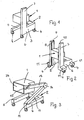
- the test device has a measuring head 1, which is provided on a movable frame 2.
- the frame 2 has a U-shaped frame part 3, on the underside wheels or rollers 4 are mounted.
- the frame 2 is advantageously supported on four wheels 4, which are located at both ends of the mutually parallel legs 5 and 6 of the frame part 3.
- the wheels 4 are mounted rotatably about vertical axes on the frame part legs 5, 6.
- the measuring head 1 is located in the region above the frame part legs 5, 6, so that there is no danger of tipping when moving the frame 2 with the measuring head 1.
- the measuring head 1 is rigidly attached to the column 7.
- the ground clearance of the measuring head 1 corresponds in this case the usual ground clearance of the tail lights to be measured.
- the measuring head 1 is in the longitudinal direction of the column 7 adjustable.
- the measuring head 1 is infinitely adjustable, so that it can be adjusted to measure the vehicle rear light in any required position.
- the measuring head 1 at the Pillar 7 is also the possibility for the measuring head 1 at the Pillar 7 to provide detent positions.
- the position of the detent positions corresponds for example to the ground clearances of the tail lights to be measured according to the most important standards, for example in Europe, the USA or Japan.
- the measuring head 1 is supported by two columns 7, 8 which protrude perpendicularly from the free ends of the frame part legs 5, 6.
- the measuring head 1 can be fixedly mounted between the columns 7, 8.
- the measuring head 1 is preferably infinitely variable in height between the columns 7, 8.
- the columns 7, 8 are provided for this purpose on their sides facing each other with guides 9, 10 along which the measuring head 1 is displaceable.
- a (not shown) drive is advantageously used, with which the measuring head 1 can be adjusted to the desired height.
- the wheels or rollers 4 are provided on lateral arms 11, which are provided at the two ends of the frame part legs 5, 6.
- Fig. 3 shows an embodiment in which at the free end of the leg 6 of the U-shaped frame 2, the one end of an arm 11 is pivotally mounted about a horizontal axis 12.
- a further arm 13 is articulated, which carries the measuring head 1 at its free end.
- the two arms 11, 13 are pivotable relative to each other about their common axis 14, which is parallel to the pivot axis 12.
- the measuring head 1 is pivotally connected to the arm 13 about a horizontal axis 15.
- the two arms 11, 13 can be pivoted against each other by motor, so that the measuring head 1 can be adjusted to any desired altitude.
- the actuator designed for such a kind of lift Adjustment devices 11, 13 is known and is therefore not explained in detail.
- the two arms 11, 13 lie one above the other in a vertical plane and can be pivoted so far against each other that they lie on each other.
- the measuring head 1 is located in the region between the two frame part legs 5, 6, which have such a distance from each other that the measuring head 1 can reach in its lowest position between the two legs 5, 6.
- the Leuchtenprüf has in this situation only a small height.
- the arm 11 of the adjusting device can be connected at its free end and articulated about two axes with the frame 2.
- the horizontal pivot axis 12 may still be provided a vertical pivot axis.
- the adjusting device 11, 13 are pivoted relative to the frame 2 also about this vertical axis.
- the measuring head 1 can be varied.
- the luminaire testing device has a substantially U-shaped frame 2, the two legs 5, 6, in contrast to the previous embodiments are not parallel to each other, but converge in the direction of their free ends.
- a height-adjustable telescopic column 16 At the free end of the frame part leg 6 is a height-adjustable telescopic column 16, with which the measuring head 1 can be adjusted continuously in height.
- the telescopic column 16 has a fixed at the free end of the frame part leg 6 column part 17 which receives the height-adjustable column portion 18.
- a monitor 19 and a keyboard 20 are mounted. Both parts 19, 20 are advantageously on a support unit 38 which is pivotable about the vertical axis 21 of the column part 18.
- the keyboard 20 can be made in a manner to be described during the measurement inputs from a (not represented) computers are processed. He is housed in the embodiment in a housing 22 of the measuring head 1. In this housing 22, a printer 23 is advantageously arranged, can be made with the protocol printouts and the like. It is of course possible to provide the computer and / or the printer centrally and to transfer the data via the network or wirelessly from the keyboard 20.
- the column part 18 may be driven by a motor in the vertical direction. But it is also possible, the adjusting device 16 in such a way that the column part 18 is pushed up by hand and is automatically blocked in any desired adjustment position.
- a handle 24 may be provided on the column part 18 and / or on the housing 22 of the measuring head 1, with which the height adjustment can be made easy.
- This test covers all essential active components of a vehicle tail lamp. The test determines if the tail lamp complies with the legal requirements regarding the luminous intensity of its components in certain directions, e.g. in HO-VO direction, is sufficient. With the light testing device the light intensity of the components of the tail light is checked.
- Fig. 5 shows the basic measurement setup.
- the tail lamp to be measured is designated 25.
- the emitted by her, marked by arrows rays 26 fall on the measuring head 1, which has a plate pack 27 of a plurality of perforated plates in the embodiment.
- the plate pack 27 forms a matte black beam selection unit.
- the openings 28 in the perforated plates of the plate package 27 let the emitted by the tail lamp 25 beams 26 through.
- the rays 26 occur in different Directions from the light window 29 of the tail lamp 25 off.
- the beams 26 are selected in a manner to be described so that they emerge directed on the outlet side 30 of the plate pack 27. In the illustrated embodiment, the beams 26 'emerge in the horizontal direction.
- the exit side 30 of the plate pack 27 is detected by a camera 31 via a ground glass 34. It is advantageous a digital camera, which is connected to the computer.
- the emerging from the exit side 30 rays 26 'form an image of the local distribution of the luminance of the measured functional parts of the tail lamp 25 in the measured direction. This image is detected by the camera 31 and can be further processed by the connected computer. With the camera 31, the local distribution of the luminance in the measured direction can be detected accurately, with a relatively coarse positioning of the luminaire testing device is sufficient for the measurement.
- a measurement protocol can be printed out via the printer 23. Depending on the software used, the measurement results can be printed in diagram form and the like, so that the measurement result can be optimally processed for the respective application.
- the measurement results can also be displayed on the monitor 19, which can be, for example, a flat screen.
- the measurement results supplied by the camera 31 can be compared, for example, with measured data stored in a data memory.
- deviations between the measurement data specified by the respective standard and the measured actual data can be easily recognized and displayed, for example on the flat screen or on the measurement protocol to be printed out.
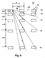
- the structure of the plate pack 27 will be described in more detail. It consists of individual, mutually parallel plates 32, which are each formed as perforated plates.
- the plates 32 are the same design, but arranged at different distances from each other. The distances between the plates 32 are chosen so that only light can pass through directly adjacent openings 28 of the plates 32. This prevents that, for example, a beam 26 falling obliquely on the plate pack 27 reaches the exit side 30 unhindered.
- the formula applies to circular openings and to a hexagonal (honeycomb) hole arrangement.
- the minimum hole center distance should be used instead of the hole center distance R.
- a minimum number of plates 32 can be achieved with maximum spacing of the plates 32. In this way, for a given thickness of the plate pack 27 and a predetermined number of plates 32, the minimum number of plates can be determined.
- Fig. 6 are exemplified four beams 1 to 4, which pass through the plate pack 27. It can be seen that rays incident obliquely into the openings 28 do not reach the exit side 30 unhindered, but are intercepted at the webs 33 located between the openings 28.
- a ground glass 34 ( Fig. 3 and 4 ), which images the light area of the tail light.
- the camera 31 captures this image on the ground glass 34.
- the plate package 27 is housed protected in the housing 22. At the light entry side of the housing 22 may be provided a lichtduchine, the direction of the rays in the passage not changing disc.
- the opening diameter D is 3 mm, the hole center distance R 5 mm and the thickness d of the plate 32 1 mm.
- the plates 32 may have a size, for example, from 320 to 420 mm, the measuring field being, for example, 300 to 400 mm. These details are only examples and do not limit the design of the measuring head 1 to such dimensions. Basically, the plates 32 can be of any suitable size, regardless of the desired recording area and the size of the measuring head. 1
- the area cross section of the plates 32 is advantageously so large that the entire, emitted by the luminaire to be measured 25 light is detected. If larger luminaires are to be measured, it may be advantageous not to increase the cross-sectional area of the plate pack 27, but to successively measure the emission areas of the tail lamp 25 with the measuring head 1. On the computer side, it is readily possible with appropriate software to process the different measuring ranges in such a way that a uniform measuring range is displayed as the result of the measurement.
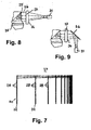
- Fig. 8 shows a measuring arrangement upon measurement of the tail lamp 25 of a motor vehicle 35.
- the emerging from the tail lamp 25 to the rear rays 26 enter the plate pack 27 of the measuring head 1.
- the rays 26 pass through the openings 28 of the plates 32 in the manner described and get on the output-side ground glass 34.
- the luminous surface of the tail lamp to be measured 25 is formed. This image is detected by the camera 31, which is directed perpendicular to the ground glass 34.
- a deflection mirror 36 is provided, on which the camera 31 is directed.
- the deflection mirror 36 is housed in the housing 22 of the measuring head 1. It is also possible to deflect the deflecting mirror 36 on the outside of the measuring head housing 22, so that it can be swung away if necessary and the camera 31 during the measuring a position relative to the plate package 27 accordingly Fig. 8 can take.
- the ratio X of hole diameter D to the thickness of the plate pack 27 is exemplarily in the range of about 1:10 to about 1:40, preferably in the range of about 1:20 to about 1:30.
- the specified ratio X is to be as large as possible so that the ground glass 34 has a maximum brightness and the exposure time of the camera 31 can be kept small.
- the angle of view corresponding to this ratio X by the beam selection unit arctan (X) should be significantly smaller than the so-called beam width of the sharpest bundled luminaire function to be measured, e.g. the bypass light. The measurement result can then be associated with high accuracy of the light intensity in the measured direction.
- the measuring head 1 When measuring, the measuring head 1 does not have to be arranged at an exact distance from the luminaire 25 to be measured.
- the brightness of the luminaire 25, which decreases with the square of the distance, is compensated for by the camera 31 seeing and detecting through each opening 28 of the plate pack 27 an area of the luminaire 25 increasing with the square of the distance. In this way, a self-compensation is achieved, so that a precisely maintained distance between the measuring head 1 and the lamp 25 is not required.
- the light intensity in HO-VO direction is preferably measured in the illustrated and described embodiment. If the luminaire testing device is to be adjusted in the horizontal direction relative to the vehicle, the device is moved, for example, with rollers on rails which extend in front of and behind the vehicle transversely to its longitudinal direction. If the camera 31 is a black-and-white camera, color filters are used to reproduce the (standardized) spectral sensitivity curve of the human eye. However, it is also possible to use a color camera, for example an RGB CCD camera, even if the color coordinates are correct should be.
- the spectral sensitivity curves of the three RGB channels of this camera are matched by color filters to the CIE standard curves, so that the spectral sensitivity curves of the RGB channels of the camera 31 correspond to the spectral sensitivity curve of the three eye sensor types. It is then possible to enable a color location measurement with such a color camera 31.
- the color is described in a CIE color triangle with two numbers, the coordinates x and y of the so-called color locus in the CIE triangle.
- Legislation prescribes the color loci which, for example, correspond to flashing lights with the color "yellow / orange" and, for example, with brake lights and tail lights with the color "red" of a specific wavelength.
- the directivity of the plate pack 27 results from the ratio X of hole diameter D to the thickness of the plate pack 27.
- X the ratio of hole diameter D to the thickness of the plate pack 27.
- This opening angle is definitely much smaller than the club width of the measured tail lamp function to choose. This ensures that the measurement result with high accuracy of the light intensity to be determined in HO-HV direction can be assigned.
- the light testing device not only tail lights, but also headlights of vehicles can be measured.
- the measuring head 1 is provided on the Leuchtenprüf planted that he can be adjusted not only in height to the lamp to be measured 25, but also in an exact horizontal position.
Abstract
Description
Die Erfindung betrifft eine Leuchtenprüfeinheit für Fahrzeuge, vorzugsweise für Kraftfahrzeuge, nach dem Oberbegriff des Anspruches 1.The invention relates to a lamp test unit for vehicles, preferably for motor vehicles, according to the preamble of
Es sind Leuchtenprüfeinrichtungen bekannt, mit denen das von einer Rückleuchte abgestrahlte Licht erfasst und im Hinblick auf seine Lichtstärke überprüft wird. Solche Leuchteneinrichtungen haben einen Messkopf mit einer Sammellinse und einer Fotozelle. Der Messkopf arbeitet somit im Wesentlichen wie ein Belichtungsmesser, der die von der zu prüfenden Leuchte ausgesandten Strahlen erfasst. Mit dem Messkopf kann festgestellt werden, ob die Lichtstärke der zu messenden Leuchte den gesetzlichen Anforderungen entspricht. Mit dieser Leuchtenprüfeinrichtung können Rückleuchten grob gemessen werden. Problematisch ist der Einfluss von Umgebungslicht, der den Messvorgang beeinträchtigen kann.Luminaire testing devices are known with which the light emitted by a rear light is detected and checked with regard to its light intensity. Such lighting devices have a measuring head with a converging lens and a photocell. The measuring head thus operates essentially like a light meter, which detects the rays emitted by the lamp to be tested. The measuring head can be used to determine whether the luminous intensity of the luminaire to be measured meets the legal requirements. Tail lights can be roughly measured with this light testing device. The problem is the influence of ambient light, which can affect the measurement process.
Es ist eine Leuchtenprüfeinrichtung für Kraftfahrzeuge bekannt (
Es ist auch eine Einrichtung zur Prüfung der Kollimation und des lotrechten Einfalls des Lichtes einer Leuchte bekannt (
Schließlich ist eine Leuchtenprüfeinrichtung für Kraftfahrzeuge bekannt (DATABASE WPI Section EI, Week 198348 Derwent Publications Ltd., London, GB; Class S02, AN 1983-832280 XP002315699-&
Der Erfindung liegt die Aufgabe zugrunde, die gattungsgemäße Leuchtenprüfeinrichtung so auszubilden, daß bei einfacher konstruktiver Gestaltung der Meßvorgang genau und zuverlässig durchgeführt werden kann.The invention has for its object to form the generic Leuchtenprüfeinrichtung so that with a simple structural design of the measuring process can be performed accurately and reliably.
Diese Aufgabe wird bei der gattungsgemäßen Leuchtenprüfeinrichtung erfindungsgemäß mit den Merkmalen des Anspruches 1 gelöst.This object is achieved in the generic luminaire testing device according to the invention with the features of
Der Meßkopf ist mit der Strahlenselektionseinheit versehen, in die die von der zu messenden Leuchte ausgesandten Strahlen gelangen. Sie treten in die Durchtrittsöffnungen ein und werden beim Austritt aus der Strahlenselektionseinheit von der Strahlenerfassungseinheit erfaßt. Sie liefert entsprechend dem erfaßten Abbild Signale, die einer weiteren Verarbeitung zugeführt werden. Mit der erfindungsgemäßen Leuchtenprüfeinrichtung ist eine genaue Messung der Leuchte möglich. Es kann die örtliche Verteilung der Leuchtdichte der Leuchte in einer bestimmten Richtung, z. B. HO-VO-Richtung, zuverlässig erkannt werden. Beim Meßvorgang ist eine genaue Positionierung der Leuchtenprüfeinrichtung in vertikaler, horizontaler und/oder longitudinaler Richtung in bezug auf die Leuchte nicht notwendig. Es reicht für diese Richtungen eine relativ grobe Positionierung für eine zuverlässige Messung aus. Die Leuchtenprüfeinrichtung kann auch zur Messung von dynamischen Leuchten, zur Messung von Rückstrahlern und sogar zur Messung von Scheinwerfern eingesetzt werden. Die Strahlenselektionseinheit sorgt dafür, daß nur das von der zu prüfenden Leuchte ausgesandte Licht aus der Strahlenselektionseinheit austritt und von der Strahlenerfassungseinheit erfaßt wird. Mit der Strahlenselektionseinheit lassen sich Lichtstärken in bestimmten Richtungen messen. Um den Anteil an Umgebungslicht, z.B. bei Reflexionen auf der Leuchtenoberfläche in der gemessenen Richtung, zumindest weitgehend auszuschalten, wird dieser Anteil vorteilhaft per Software eliminiert. So kann die rechnerische Integration der Bildhelligkeit auf denjenigen Bildausschnitt beschränkt werden, der zur gemessenen Leuchte gehört. Eine weitere Möglichkeit besteht darin, ein Bild bei ausgeschalteter Leuchte aufzunehmen (Dunkelmessung) und vom Meßbild zu subtrahieren.The measuring head is provided with the beam selection unit into which the rays emitted by the lamp to be measured pass. They enter into the passage openings and are detected by the radiation detection unit on exit from the beam selection unit. It supplies, according to the detected image, signals which are sent for further processing. With the luminaire testing device according to the invention, an accurate measurement of the luminaire is possible. It can be the local distribution of the luminance of the lamp in a particular direction, z. B. HO-VO direction, reliably detected. During the measuring process, an accurate positioning of the luminaire testing device in the vertical, horizontal and / or longitudinal direction with respect to the luminaire is not necessary. It is sufficient for these directions a relatively rough positioning for a reliable measurement. The luminaire testing device can also be used to measure dynamic luminaires, to measure reflectors and even to measure headlamps. The beam selection unit ensures that only the light emitted by the lamp to be tested light exits the beam selection unit and is detected by the radiation detection unit. With the beam selection unit, light intensities in specific directions can be measured. To at least largely eliminate the proportion of ambient light, for example reflections on the luminaire surface in the measured direction, this proportion is advantageously eliminated by software. Thus, the computational integration of the image brightness can be limited to the image section that belongs to the measured luminaire. Another possibility is to take a picture with the light off (dark measurement) and to subtract it from the measurement image.
Weitere Merkmale der Erfindung ergeben sich aus den weiteren Ansprüchen, der Beschreibung und den Zeichnungen.Further features of the invention will become apparent from the other claims, the description and the drawings.
Die Erfindung wird anhand einiger in den Zeichnungen dargestellter Ausführungsbeispiele näher erläutert. Es zeigen
- Fig. 1
- in perspektivischer und vereinfachter Darstellung eine erste Ausführungsform einer erfindungsgemäßen Leuchtenprüfeinrichtung,
- Fig. 2 bis Fig. 4
- in Darstellungen entsprechend
Fig. 1 weitere Ausführungsformen von erfindungsgemäßen Leuchtenprüfeinrichtungen, - Fig. 5
- in schematischer Darstellung das Meßprinzip unter Verwendung der erfindungsgemäßen Leuchtenprüfeinrichtung,
- Fig. 6
- in schematischer Darstellung den Strahlenverlauf innerhalb der Strahlenselektionseinheit in Lochblechausführung,
- Fig. 7
- in schematischer Darstellung einen Schnitt durch die Strahlenselektionseinheit in Lochblechausführung,
- Fig. 8
- in schematischer Darstellung die erfindungsgemäße Leuchtenprüfeinrichtung während des Meßvorganges,
- Fig. 9
- in einer Darstellung entsprechend
Fig. 8 ein weiteres Meßverfahren.
- Fig. 1
- in a perspective and simplified representation of a first embodiment of a luminaire testing device according to the invention,
- Fig. 2 to Fig. 4
- in representations accordingly
Fig. 1 further embodiments of luminaire testing devices according to the invention, - Fig. 5
- a schematic representation of the measuring principle using the luminaire testing device according to the invention,
- Fig. 6
- a schematic representation of the beam path within the beam selection unit in perforated plate design,
- Fig. 7
- a schematic representation of a section through the beam selection unit in perforated plate design,
- Fig. 8
- a schematic representation of the luminaire testing device according to the invention during the measuring process,
- Fig. 9
- in a representation accordingly
Fig. 8 another measuring method.
Mit der Leuchtenprüfeinrichtung können Rückleuchten von Fahrzeugen auf ihre Funktionstüchtigkeit geprüft werden. Mit der Prüfeinrichtung können die Lichtstärken von Rücklicht, Bremslicht, Blinklicht, Nebelschlußlicht und Rückfahrscheinwerfer gemessen werden.Taillights of vehicles can be checked for their functionality with the light testing device. With the test equipment, the light levels of the tail light, brake light, flashing light, rear fog light and reversing light can be measured.
Die Prüfeinrichtung hat einen Meßkopf 1, der an einem verfahrbaren Gestell 2 vorgesehen ist. Das Gestell 2 hat einen U-förmigen Gestellteil 3, an dessen Unterseite Räder oder Rollen 4 gelagert sind. Das Gestell 2 ist vorteilhaft auf vier Rädern 4 abgestützt, die sich an beiden Enden der parallel zueinander liegenden Schenkel 5 und 6 des Gestellteiles 3 befinden. Vorteilhaft sind die Räder 4 um vertikale Achsen drehbar an den Gestellteilschenkeln 5, 6 gelagert.The test device has a measuring
Vom freien Ende des Gestellteilschenkels 6 steht senkrecht eine Säule 7 ab, an der der Meßkopf 1 gelagert ist. Der Meßkopf 1 liegt im Bereich oberhalb der Gestellteilschenkel 5, 6, so daß keine Kippgefahr beim Verfahren des Gestelles 2 mit dem Meßkopf 1 besteht. Bei einer einfachen Ausführungsform ist der Meßkopf 1 an der Säule 7 starr befestigt. Der Bodenabstand des Meßkopfes 1 entspricht in diesem Falle dem üblichen Bodenabstand der zu vermessenden Rückleuchten.From the free end of the
Es ist selbstverständlich möglich, den Meßkopf 1 in Längsrichtung der Säule 7 verstellbar anzuordnen. Vorteilhaft ist in einem solchen Fall der Meßkopf 1 stufenlos verstellbar, so daß er zum Vermessen der Fahrzeugrückleuchte in jede erforderliche Lage eingestellt werden kann. Es besteht auch die Möglichkeit, für den Meßkopf 1 an der Säule 7 Rastpositionen vorzusehen. Die Lage der Rastpositionen entspricht beispielsweise den Bodenabständen der zu vermessenden Rückleuchten gemäß den wichtigsten Normen beispielsweise in Europa, den U.S.A. oder Japan.It is of course possible to arrange the measuring
Bei der Ausführungsform gemäß
Um eine hohe Standfestigkeit der Leuchtenprüfeinrichtung zu erreichen, sind die Räder bzw. Rollen 4 an seitlichen Auslegern 11 vorgesehen, die an den beiden Enden der Gestellteilschenkel 5, 6 vorgesehen sind.In order to achieve a high stability of the luminaire testing device, the wheels or
Die beiden Arme 11, 13 liegen in einer vertikalen Ebene übereinander und können so weit gegeneinander geschwenkt werden, daß sie aufeinander liegen. Der Meßkopf 1 befindet sich im Bereich zwischen den beiden Gestellteilschenkeln 5, 6, die einen solchen Abstand voneinander haben, daß der Meßkopf 1 in seiner untersten Lage zwischen die beiden Schenkel 5, 6 gelangen kann. Die Leuchtenprüfeinrichtung weist in dieser Lage nur eine geringe Bauhöhe auf.The two
Der Arm 11 der Verstelleinrichtung kann an seinem freien Ende auch um zwei Achsen gelenkig mit dem Gestell 2 verbunden sein. Zusätzlich zu der horizontalen Schwenkachse 12 kann noch eine vertikale Schwenkachse vorgesehen sein. Dadurch kann die Verstelleinrichtung 11, 13 relativ zum Gestell 2 auch um diese vertikale Achse geschwenkt werden. Dadurch läßt sich der Meßkopf 1 vielfältig einstellen.The
Die Leuchtenprüfeinrichtung nach
Der Säulenteil 18 kann in Höhenrichtung motorisch antreibbar sein. Es ist aber auch möglich, die Verstelleinrichtung 16 so auszubilden, daß der Säulenteil 18 von Hand aufwärts geschoben wird und in jeder gewünschten Verstellage automatisch blockiert wird. Um diese manuelle Verstellung zu erleichtern, kann am Säulenteil 18 und/oder am Gehäuse 22 des Meßkopfes 1 ein Griff 24 vorgesehen sein, mit dem sich die Höhenverstellung einfach vornehmen läßt.The
Mit der Leuchtenprüfeinrichtung werden bereits bauartgeprüfte und zugelassene Rückleuchten von Fahrzeugen auf ihre Funktionsfähigkeit geprüft. Diese Prüfung umfaßt alle wesentlichen aktiven Komponenten einer Fahrzeugrückleuchte. Die Prüfung stellt fest, ob die Rückleuchte den gesetzlichen Vorschriften hinsichtlich der Lichtstärke ihrer Komponenten in bestimmten Richtungen, z.B. in HO-VO-Richtung, genügt. Mit der Leuchtenprüfeinrichtung wird die Lichtstärke der Komponenten der Rückleuchte geprüft.With the luminaire tester already approved and approved taillights of vehicles are tested for their functionality. This test covers all essential active components of a vehicle tail lamp. The test determines if the tail lamp complies with the legal requirements regarding the luminous intensity of its components in certain directions, e.g. in HO-VO direction, is sufficient. With the light testing device the light intensity of the components of the tail light is checked.
Anhand von
In ![]()
Hierbei ist a(0) = d. Dabei bedeuten:
- d
- Blechdicke
- R
- Lochmittenabstand, Rastermaß
- D
- Lochdurchmesser
Here, a (0) = d. Where:
- d
- sheet thickness
- R
- Hole center distance, pitch
- D
- Hole diameter
Die Formel gilt für kreisförmige Öffnungen und für eine hexagonale (wabenartige) Lochanordnung. Für andere Öffnungsanordnungen ist anstelle des Lochmittenabstandes R der minimale Lochmittenabstand anzusetzen.The formula applies to circular openings and to a hexagonal (honeycomb) hole arrangement. For other opening arrangements, the minimum hole center distance should be used instead of the hole center distance R.
Aufgrund der obigen Formel kann sehr einfach eine minimale Anzahl von Platten 32 bei maximalem Abstand der Platten 32 erzielt werden. Auf diese Weise kann bei einer vorgegebenen Dicke des Plattenpaketes 27 und einer vorgegebenen Zahl von Platten 32 die minimale Zahl der Platten bestimmt werden.Due to the above formula, a minimum number of
In
Hinter dem Plattenpaket 27 an der Austrittsseite 30 ist eine Mattscheibe 34 (
Bei einem Ausführungsbeispiel beträgt der Öffnungsdurchmesser D 3 mm, der Lochmittenabstand R 5 mm und die Dicke d der Platte 32 1 mm. Die Platten 32 können eine Größe beispielsweise von 320 auf 420 mm haben, wobei das Meßfeld beispielsweise 300 zu 400 mm beträgt. Diese Angaben stellen lediglich Beispiele dar und beschränken die Ausbildung des Meßkopfes 1 nicht auf solche Abmessungen. Grundsätzlich können die Platten 32 jede geeignete Größe haben, und zwar unabhängig vom gewünschten Aufnahmebereich und der Größe des Meßkopfes 1.In one embodiment, the opening diameter D is 3 mm, the hole
Der Flächenquerschnitt der Platten 32 ist vorteilhaft so groß, daß das gesamte, von der zu vermessenden Leuchte 25 abgestrahlte Licht erfaßt wird. Sind größere Leuchten zu vermessen, kann es vorteilhaft sein, nicht die Querschnittsfläche des Plattenpaketes 27 zu vergrößern, sondern mit dem Meßkopf 1 nacheinander die Abstrahlbereiche der Rückleuchte 25 zu vermessen. Rechnerseitig ist es bei entsprechender Software ohne weiteres möglich, die verschiedenen Meßbereiche so zu verarbeiten, daß als Meßergebnis ein einheitlicher Meßbereich angezeigt wird.The area cross section of the
Es ist auch möglich, die Kamera 31 so anzuordnen (
Das Verhältnis X von Lochdurchmesser D zur Dicke des Plattenpaketes 27 liegt beispielhaft im Bereich von etwa 1:10 bis etwa 1:40, vorzugsweise im Bereich von etwa 1:20 bis etwa 1:30. Das angegebene Verhältnis X ist einerseits möglichst groß zu wählen, damit die Mattscheibe 34 eine maximale Helligkeit hat und die Belichtungszeit der Kamera 31 klein gehalten werden kann. Andererseits sollte der diesem Verhältnis X entsprechende Blickwinkel durch die Strahlenselektionseinheit arctan (X) deutlich kleiner sein als die sogenannte Keulenbreite der schärfstgebündelten zu messenden Leuchtenfunktion, z.B. der Nebenschlußleuchte. Das Meßergebnis kann dann mit hoher Genauigkeit der Lichtstärke in der gemessenen Richtung zugeordnet werden.The ratio X of hole diameter D to the thickness of the
Bei der Messung muß der Meßkopf 1 nicht in einem genauen Abstand zur zu vermessenden Leuchte 25 angeordnet werden. Die mit dem Quadrat der Entfernung abnehmende Helligkeit der Leuchte 25 wird dadurch kompensiert, daß die Kamera 31 durch jede Öffnung 28 des Plattenpaketes 27 eine mit dem Quadrat der Entfernung zunehmende Fläche der Leuchte 25 sieht und erfaßt. Auf diese Weise wird eine Selbstkompensierung erreicht, so daß ein genau einzuhaltender Abstand zwischen dem Meßkopf 1 und der Leuchte 25 nicht erforderlich ist.When measuring, the measuring
Bei der Messung wird im dargestellten und beschriebenen Ausführungsbeispiel vorzugsweise die Lichtstärke in HO-VO-Richtung gemessen. Soll die Leuchtenprüfeinrichtung in horizontaler Richtung relativ zum Fahrzeug eingestellt werden, wird die Einrichtung beispielsweise mit Rollen auf Schienen verfahren, die vor bzw. hinter dem Fahrzeug quer zu dessen Längsrichtung verlaufen. Ist die Kamera 31 eine Schwarz-Weiß-Kamera, wird mit Farbfiltern die (genormte) spektrale Empfindlichkeitskurve des menschlichen Auges nachgebildet. Es kann aber auch eine Farbkamera eingesetzt werden, beispielsweise eine RGB-CCD-Kamera, wenn auch die Farborte bstimmt werden sollen. Die spektralen Empfindlichkeitskurven der drei RGB-Kanäle dieser Kamera werden durch Farbfilter den CIE-genormten Kurven angepaßt, so daß die Spektralempfindlichkeitskurven der RGB-Kanäle der Kamera 31 den spektralen Empfindlichkeitskurve der drei Augensensorarten entsprechen. Es ist dann möglich, mit einer solchen Farbkamera 31 eine Farbortmessung zu ermöglichen. Die Farbe wird bei einem CIE-Farbdreieck mit zwei Zahlen beschrieben, die Koordinaten x und y des sogenannten Farbortes im CIE-Dreieck. Der Gesetzgeber schreibt die Farborte vor, die zum Beispiel bei Blinkleuchten mit der Farbe "Gelb/Orange" und beispielsweise bei Brems- und Schlußleuchten mit der Farbe "Rot" einer bestimmten Wellenlänge entsprechen.In the measurement, the light intensity in HO-VO direction is preferably measured in the illustrated and described embodiment. If the luminaire testing device is to be adjusted in the horizontal direction relative to the vehicle, the device is moved, for example, with rollers on rails which extend in front of and behind the vehicle transversely to its longitudinal direction. If the
Die Richtwirkung des Plattenpaketes 27 ergibt sich aus dem Verhältnis X von Lochdurchmesser D zur Dicke des Plattenpaketes 27. Bei einem Verhältnis von beispielsweise 4 mm zu 100 mm, d.h. 1:25, ergibt sich ein Öffnungswinkel von +/- arctan (0,02) = +/- 1,15°. Dieser Öffnungswinkel ist auf jeden Fall wesentlich kleiner als die Keulenbreite der gemessenen Rückleuchtenfunktion zu wählen. Dadurch ist sichergestellt, daß das Meßergebnis mit hoher Genauigkeit der zu bestimmenden Lichtstärke in HO-HV-Richtung zugeordnet werden kann.The directivity of the
Mit der Leuchtenprüfeinrichtung können nicht nur Rückleuchten, sondern auch Scheinwerfer von Fahrzeugen vermessen werden.With the light testing device not only tail lights, but also headlights of vehicles can be measured.
Der Meßkopf 1 ist so an der Leuchtenprüfeinrichtung vorgesehen, daß er nicht nur in der Höhe auf die zu vermessende Leuchte 25 eingestellt werden kann, sondern auch in eine exakte horizontale Lage.The measuring
Claims (6)
- Testing device for vehicle lights, in particular for motor vehicles with at least one measuring head (1) for the coverage of the rays (26) emitted from the light (25) to be tested, the measuring head (1) comprising a ray selection unit (27, 37), having passage openings (28) for the rays (26), behind which is situated at least one ray coverage unit (31), the ray selection unit (27) consisting of perforated plates (32) arranged one behind the other, all passage openings (28) being equally sized and all perforated plates (32) being equally shaped, all passage openings (28) in all perforated plates (32) having the same hole centre distance R from another and all being either circular or hexagonal,
characterised in that the distance of the perforated plates (32) from one another corresponds to the relation a(i + 1) = a(i) x R/D, where i = 0, 1, 2 ... D the diameter of the passage openings (28) and a(0) the thickness of the perforated plate (32). - Device according to claim 1,
characterised in that the relation (X) of the diameter (D) of the passage opening (28) to the thickness of the ray selection unit (27, 37) is situated in the range between approximately 1:10 and approximately 1:40, advantageously between approximately 1:20 and approximately 1:30. - Device according to claim 1 or 2,
characterised in that the measuring head (1) comprises at the outlet end of the rays (26) a focussing screen (34). - Device according to one of the claims 1 to 3,
characterised in that the ray coverage unit (31) is a camera, advantageously a CCD-camera and/or a RGB-camera. - Device according to one of the claims 1 to 4,
characterised in that the measuring head (1) is fixed, preferably adjustably supported at a frame (2). - Device according to one of the claims 1 to 5,
characterised in that the ray coverage unit (31) is connected to a computer.
Applications Claiming Priority (2)
| Application Number | Priority Date | Filing Date | Title |
|---|---|---|---|
| DE10348231 | 2003-10-13 | ||
| DE10348231A DE10348231A1 (en) | 2003-10-13 | 2003-10-13 | Luminaire testing device for vehicles, preferably for motor vehicles |
Publications (2)
| Publication Number | Publication Date |
|---|---|
| EP1524512A1 EP1524512A1 (en) | 2005-04-20 |
| EP1524512B1 true EP1524512B1 (en) | 2008-03-12 |
Family
ID=34353445
Family Applications (1)
| Application Number | Title | Priority Date | Filing Date |
|---|---|---|---|
| EP04023865A Not-in-force EP1524512B1 (en) | 2003-10-13 | 2004-10-07 | Testing device for vehicle lights, in particular for motor vehicles |
Country Status (4)
| Country | Link |
|---|---|
| EP (1) | EP1524512B1 (en) |
| AT (1) | ATE389167T1 (en) |
| DE (2) | DE10348231A1 (en) |
| ES (1) | ES2303620T3 (en) |
Families Citing this family (3)
| Publication number | Priority date | Publication date | Assignee | Title |
|---|---|---|---|---|
| DE102008025530B4 (en) * | 2008-05-28 | 2012-11-22 | Audi Ag | Device for testing the function of a lighting device of a motor vehicle |
| CN104458210B (en) * | 2014-11-28 | 2017-07-14 | 马瑞利汽车零部件(芜湖)有限公司 | Car headlamp automatic checkout system |
| CN105092214A (en) * | 2015-08-07 | 2015-11-25 | 江苏常诚汽车部件有限公司 | Automobile headlamp detector |
Family Cites Families (3)
| Publication number | Priority date | Publication date | Assignee | Title |
|---|---|---|---|---|
| SU996897A1 (en) * | 1981-08-31 | 1983-02-15 | за вители | Instrument for checking vehicle head-light position |
| US4498767A (en) * | 1982-09-07 | 1985-02-12 | Teletype Corporation | Apparatus for measuring light |
| US5392111A (en) * | 1990-10-09 | 1995-02-21 | Honda Giken Kogyo Kabushiki Kaisha | Method of measuring and adjusting optical axis of headlight |
-
2003
- 2003-10-13 DE DE10348231A patent/DE10348231A1/en not_active Ceased
-
2004
- 2004-10-07 EP EP04023865A patent/EP1524512B1/en not_active Not-in-force
- 2004-10-07 ES ES04023865T patent/ES2303620T3/en active Active
- 2004-10-07 AT AT04023865T patent/ATE389167T1/en active
- 2004-10-07 DE DE502004006472T patent/DE502004006472D1/en active Active
Also Published As
| Publication number | Publication date |
|---|---|
| ATE389167T1 (en) | 2008-03-15 |
| DE10348231A1 (en) | 2005-05-04 |
| EP1524512A1 (en) | 2005-04-20 |
| ES2303620T3 (en) | 2008-08-16 |
| DE502004006472D1 (en) | 2008-04-24 |
Similar Documents
| Publication | Publication Date | Title |
|---|---|---|
| EP0683384B1 (en) | Apparatus for measuring the colour valve of a luminous flux | |
| EP1669715B1 (en) | Chassis measurement device | |
| DE102012102651B3 (en) | Test device and test method for a traffic monitoring device with a laser scanner | |
| DE10149780B4 (en) | Device for illuminating a measuring surface and device and method for determining the visual properties of bodies | |
| DE3843876C2 (en) | ||
| EP3736555B1 (en) | Vehicle calibration tool | |
| EP0279191A2 (en) | Device for contactless measurement of remission | |
| DE112013005764T5 (en) | Test system and test lighting device | |
| DE3926349A1 (en) | Optical defect inspection arrangement for flat transparent material - passes light via mirror forming image of illumination pupil on camera lens of photoreceiver | |
| WO2004017016A2 (en) | Device and method for measuring the dimensions of a body | |
| DE19961908C2 (en) | High-resolution Littrow spectrometer and method for quasi-simultaneous determination of a wavelength and a line profile | |
| WO2022112324A1 (en) | Method and gonioradiometer for the direction-dependent measurement of at least one lighting or radiometric characteristic variable of an optical radiation source installed in an object | |
| WO2014191401A1 (en) | Method for determining the refractive power of a transparent object, and corresponding device | |
| DE69722551T2 (en) | Spectrometer with an oriented-shaped slit | |
| EP3382271A1 (en) | Device for adapting the intensity of radiation | |
| EP1524512B1 (en) | Testing device for vehicle lights, in particular for motor vehicles | |
| DE10156804B4 (en) | Optical measuring device for test strips | |
| CH697319B1 (en) | Method and apparatus for geometric calibration of optoelectronic measuring cameras. | |
| DE19633557A1 (en) | Hand measuring instrument for colour print spectra | |
| DE4138679C1 (en) | ||
| DE102017101102B3 (en) | Method and coordinate measuring device for measuring optical properties of an optical filter | |
| DE102013001449A1 (en) | Method for adjusting a distance sensor on a vehicle and measuring traverse | |
| DE19950060C2 (en) | Optoelectronic sensor device for a motor vehicle | |
| DE2718711C2 (en) | ||
| DE10004889B4 (en) | Method and device for optically recognizing local deformations, in particular bubbles, in an object |
Legal Events
| Date | Code | Title | Description |
|---|---|---|---|
| PUAI | Public reference made under article 153(3) epc to a published international application that has entered the european phase |
Free format text: ORIGINAL CODE: 0009012 |
|
| AK | Designated contracting states |
Kind code of ref document: A1 Designated state(s): AT BE BG CH CY CZ DE DK EE ES FI FR GB GR HU IE IT LI LU MC NL PL PT RO SE SI SK TR |
|
| AX | Request for extension of the european patent |
Extension state: AL HR LT LV MK |
|
| 17P | Request for examination filed |
Effective date: 20050924 |
|
| AKX | Designation fees paid |
Designated state(s): AT BE BG CH CY CZ DE DK EE ES FI FR GB GR HU IE IT LI LU MC NL PL PT RO SE SI SK TR |
|
| 17Q | First examination report despatched |
Effective date: 20061031 |
|
| GRAP | Despatch of communication of intention to grant a patent |
Free format text: ORIGINAL CODE: EPIDOSNIGR1 |
|
| RAP1 | Party data changed (applicant data changed or rights of an application transferred) |
Owner name: SCALA DESIGN GMBH |
|
| GRAS | Grant fee paid |
Free format text: ORIGINAL CODE: EPIDOSNIGR3 |
|
| GRAA | (expected) grant |
Free format text: ORIGINAL CODE: 0009210 |
|
| AK | Designated contracting states |
Kind code of ref document: B1 Designated state(s): AT BE BG CH CY CZ DE DK EE ES FI FR GB GR HU IE IT LI LU MC NL PL PT RO SE SI SK TR |
|
| REG | Reference to a national code |
Ref country code: GB Ref legal event code: FG4D Free format text: NOT ENGLISH |
|
| REG | Reference to a national code |
Ref country code: CH Ref legal event code: EP |
|
| REG | Reference to a national code |
Ref country code: IE Ref legal event code: FG4D Free format text: LANGUAGE OF EP DOCUMENT: GERMAN |
|
| REF | Corresponds to: |
Ref document number: 502004006472 Country of ref document: DE Date of ref document: 20080424 Kind code of ref document: P |
|
| PG25 | Lapsed in a contracting state [announced via postgrant information from national office to epo] |
Ref country code: FI Free format text: LAPSE BECAUSE OF FAILURE TO SUBMIT A TRANSLATION OF THE DESCRIPTION OR TO PAY THE FEE WITHIN THE PRESCRIBED TIME-LIMIT Effective date: 20080312 |
|
| REG | Reference to a national code |
Ref country code: ES Ref legal event code: FG2A Ref document number: 2303620 Country of ref document: ES Kind code of ref document: T3 |
|
| PG25 | Lapsed in a contracting state [announced via postgrant information from national office to epo] |
Ref country code: SI Free format text: LAPSE BECAUSE OF FAILURE TO SUBMIT A TRANSLATION OF THE DESCRIPTION OR TO PAY THE FEE WITHIN THE PRESCRIBED TIME-LIMIT Effective date: 20080312 Ref country code: PL Free format text: LAPSE BECAUSE OF FAILURE TO SUBMIT A TRANSLATION OF THE DESCRIPTION OR TO PAY THE FEE WITHIN THE PRESCRIBED TIME-LIMIT Effective date: 20080312 |
|
| REG | Reference to a national code |
Ref country code: IE Ref legal event code: FD4D |
|
| PG25 | Lapsed in a contracting state [announced via postgrant information from national office to epo] |
Ref country code: SK Free format text: LAPSE BECAUSE OF FAILURE TO SUBMIT A TRANSLATION OF THE DESCRIPTION OR TO PAY THE FEE WITHIN THE PRESCRIBED TIME-LIMIT Effective date: 20080312 Ref country code: SE Free format text: LAPSE BECAUSE OF FAILURE TO SUBMIT A TRANSLATION OF THE DESCRIPTION OR TO PAY THE FEE WITHIN THE PRESCRIBED TIME-LIMIT Effective date: 20080612 Ref country code: CZ Free format text: LAPSE BECAUSE OF FAILURE TO SUBMIT A TRANSLATION OF THE DESCRIPTION OR TO PAY THE FEE WITHIN THE PRESCRIBED TIME-LIMIT Effective date: 20080312 Ref country code: PT Free format text: LAPSE BECAUSE OF FAILURE TO SUBMIT A TRANSLATION OF THE DESCRIPTION OR TO PAY THE FEE WITHIN THE PRESCRIBED TIME-LIMIT Effective date: 20080818 |
|
| PG25 | Lapsed in a contracting state [announced via postgrant information from national office to epo] |
Ref country code: RO Free format text: LAPSE BECAUSE OF FAILURE TO SUBMIT A TRANSLATION OF THE DESCRIPTION OR TO PAY THE FEE WITHIN THE PRESCRIBED TIME-LIMIT Effective date: 20080312 |
|
| ET | Fr: translation filed | ||
| PLBE | No opposition filed within time limit |
Free format text: ORIGINAL CODE: 0009261 |
|
| STAA | Information on the status of an ep patent application or granted ep patent |
Free format text: STATUS: NO OPPOSITION FILED WITHIN TIME LIMIT |
|
| PG25 | Lapsed in a contracting state [announced via postgrant information from national office to epo] |
Ref country code: DK Free format text: LAPSE BECAUSE OF FAILURE TO SUBMIT A TRANSLATION OF THE DESCRIPTION OR TO PAY THE FEE WITHIN THE PRESCRIBED TIME-LIMIT Effective date: 20080312 Ref country code: IE Free format text: LAPSE BECAUSE OF FAILURE TO SUBMIT A TRANSLATION OF THE DESCRIPTION OR TO PAY THE FEE WITHIN THE PRESCRIBED TIME-LIMIT Effective date: 20080312 |
|
| 26N | No opposition filed |
Effective date: 20081215 |
|
| PG25 | Lapsed in a contracting state [announced via postgrant information from national office to epo] |
Ref country code: BG Free format text: LAPSE BECAUSE OF FAILURE TO SUBMIT A TRANSLATION OF THE DESCRIPTION OR TO PAY THE FEE WITHIN THE PRESCRIBED TIME-LIMIT Effective date: 20080612 Ref country code: EE Free format text: LAPSE BECAUSE OF FAILURE TO SUBMIT A TRANSLATION OF THE DESCRIPTION OR TO PAY THE FEE WITHIN THE PRESCRIBED TIME-LIMIT Effective date: 20080312 |
|
| PG25 | Lapsed in a contracting state [announced via postgrant information from national office to epo] |
Ref country code: MC Free format text: LAPSE BECAUSE OF NON-PAYMENT OF DUE FEES Effective date: 20081031 |
|
| REG | Reference to a national code |
Ref country code: CH Ref legal event code: PL |
|
| PG25 | Lapsed in a contracting state [announced via postgrant information from national office to epo] |
Ref country code: CY Free format text: LAPSE BECAUSE OF FAILURE TO SUBMIT A TRANSLATION OF THE DESCRIPTION OR TO PAY THE FEE WITHIN THE PRESCRIBED TIME-LIMIT Effective date: 20080312 |
|
| PG25 | Lapsed in a contracting state [announced via postgrant information from national office to epo] |
Ref country code: CH Free format text: LAPSE BECAUSE OF NON-PAYMENT OF DUE FEES Effective date: 20081031 Ref country code: LI Free format text: LAPSE BECAUSE OF NON-PAYMENT OF DUE FEES Effective date: 20081031 |
|
| PGFP | Annual fee paid to national office [announced via postgrant information from national office to epo] |
Ref country code: ES Payment date: 20091028 Year of fee payment: 6 |
|
| PGFP | Annual fee paid to national office [announced via postgrant information from national office to epo] |
Ref country code: NL Payment date: 20091231 Year of fee payment: 6 |
|
| PGFP | Annual fee paid to national office [announced via postgrant information from national office to epo] |
Ref country code: BE Payment date: 20091030 Year of fee payment: 6 |
|
| PG25 | Lapsed in a contracting state [announced via postgrant information from national office to epo] |
Ref country code: LU Free format text: LAPSE BECAUSE OF NON-PAYMENT OF DUE FEES Effective date: 20081007 Ref country code: HU Free format text: LAPSE BECAUSE OF FAILURE TO SUBMIT A TRANSLATION OF THE DESCRIPTION OR TO PAY THE FEE WITHIN THE PRESCRIBED TIME-LIMIT Effective date: 20080913 |
|
| PG25 | Lapsed in a contracting state [announced via postgrant information from national office to epo] |
Ref country code: TR Free format text: LAPSE BECAUSE OF FAILURE TO SUBMIT A TRANSLATION OF THE DESCRIPTION OR TO PAY THE FEE WITHIN THE PRESCRIBED TIME-LIMIT Effective date: 20080312 |
|
| PG25 | Lapsed in a contracting state [announced via postgrant information from national office to epo] |
Ref country code: GR Free format text: LAPSE BECAUSE OF FAILURE TO SUBMIT A TRANSLATION OF THE DESCRIPTION OR TO PAY THE FEE WITHIN THE PRESCRIBED TIME-LIMIT Effective date: 20080613 |
|
| PG25 | Lapsed in a contracting state [announced via postgrant information from national office to epo] |
Ref country code: IT Free format text: LAPSE BECAUSE OF NON-PAYMENT OF DUE FEES Effective date: 20091007 |
|
| BERE | Be: lapsed |
Owner name: SCALA DESIGN G.M.B.H. Effective date: 20101031 |
|
| REG | Reference to a national code |
Ref country code: NL Ref legal event code: V1 Effective date: 20110501 |
|
| PGRI | Patent reinstated in contracting state [announced from national office to epo] |
Ref country code: IT Effective date: 20110616 |
|
| PG25 | Lapsed in a contracting state [announced via postgrant information from national office to epo] |
Ref country code: NL Free format text: LAPSE BECAUSE OF NON-PAYMENT OF DUE FEES Effective date: 20110501 Ref country code: BE Free format text: LAPSE BECAUSE OF NON-PAYMENT OF DUE FEES Effective date: 20101031 |
|
| REG | Reference to a national code |
Ref country code: ES Ref legal event code: FD2A Effective date: 20111118 |
|
| PG25 | Lapsed in a contracting state [announced via postgrant information from national office to epo] |
Ref country code: ES Free format text: LAPSE BECAUSE OF NON-PAYMENT OF DUE FEES Effective date: 20101008 |
|
| PGFP | Annual fee paid to national office [announced via postgrant information from national office to epo] |
Ref country code: FR Payment date: 20121126 Year of fee payment: 9 |
|
| PGFP | Annual fee paid to national office [announced via postgrant information from national office to epo] |
Ref country code: IT Payment date: 20121022 Year of fee payment: 9 Ref country code: GB Payment date: 20121024 Year of fee payment: 9 |
|
| PGFP | Annual fee paid to national office [announced via postgrant information from national office to epo] |
Ref country code: AT Payment date: 20121029 Year of fee payment: 9 |
|
| PGFP | Annual fee paid to national office [announced via postgrant information from national office to epo] |
Ref country code: DE Payment date: 20121220 Year of fee payment: 9 |
|
| REG | Reference to a national code |
Ref country code: AT Ref legal event code: MM01 Ref document number: 389167 Country of ref document: AT Kind code of ref document: T Effective date: 20131007 |
|
| GBPC | Gb: european patent ceased through non-payment of renewal fee |
Effective date: 20131007 |
|
| REG | Reference to a national code |
Ref country code: DE Ref legal event code: R119 Ref document number: 502004006472 Country of ref document: DE Effective date: 20140501 |
|
| PG25 | Lapsed in a contracting state [announced via postgrant information from national office to epo] |
Ref country code: GB Free format text: LAPSE BECAUSE OF NON-PAYMENT OF DUE FEES Effective date: 20131007 |
|
| REG | Reference to a national code |
Ref country code: FR Ref legal event code: ST Effective date: 20140630 |
|
| PG25 | Lapsed in a contracting state [announced via postgrant information from national office to epo] |
Ref country code: IT Free format text: LAPSE BECAUSE OF NON-PAYMENT OF DUE FEES Effective date: 20131007 Ref country code: DE Free format text: LAPSE BECAUSE OF NON-PAYMENT OF DUE FEES Effective date: 20140501 Ref country code: AT Free format text: LAPSE BECAUSE OF NON-PAYMENT OF DUE FEES Effective date: 20131007 Ref country code: FR Free format text: LAPSE BECAUSE OF NON-PAYMENT OF DUE FEES Effective date: 20131031 |