EP3382177A1 - Control arrangement of an exhaust-gas turbocharger - Google Patents
Control arrangement of an exhaust-gas turbocharger Download PDFInfo
- Publication number
- EP3382177A1 EP3382177A1 EP18173594.5A EP18173594A EP3382177A1 EP 3382177 A1 EP3382177 A1 EP 3382177A1 EP 18173594 A EP18173594 A EP 18173594A EP 3382177 A1 EP3382177 A1 EP 3382177A1
- Authority
- EP
- European Patent Office
- Prior art keywords
- spindle
- valve disk
- lever
- control arrangement
- connecting means
- Prior art date
- Legal status (The legal status is an assumption and is not a legal conclusion. Google has not performed a legal analysis and makes no representation as to the accuracy of the status listed.)
- Granted
Links
Images




Classifications
-
- F—MECHANICAL ENGINEERING; LIGHTING; HEATING; WEAPONS; BLASTING
- F02—COMBUSTION ENGINES; HOT-GAS OR COMBUSTION-PRODUCT ENGINE PLANTS
- F02B—INTERNAL-COMBUSTION PISTON ENGINES; COMBUSTION ENGINES IN GENERAL
- F02B37/00—Engines characterised by provision of pumps driven at least for part of the time by exhaust
- F02B37/12—Control of the pumps
- F02B37/18—Control of the pumps by bypassing exhaust from the inlet to the outlet of turbine or to the atmosphere
- F02B37/183—Arrangements of bypass valves or actuators therefor
-
- Y—GENERAL TAGGING OF NEW TECHNOLOGICAL DEVELOPMENTS; GENERAL TAGGING OF CROSS-SECTIONAL TECHNOLOGIES SPANNING OVER SEVERAL SECTIONS OF THE IPC; TECHNICAL SUBJECTS COVERED BY FORMER USPC CROSS-REFERENCE ART COLLECTIONS [XRACs] AND DIGESTS
- Y02—TECHNOLOGIES OR APPLICATIONS FOR MITIGATION OR ADAPTATION AGAINST CLIMATE CHANGE
- Y02T—CLIMATE CHANGE MITIGATION TECHNOLOGIES RELATED TO TRANSPORTATION
- Y02T10/00—Road transport of goods or passengers
- Y02T10/10—Internal combustion engine [ICE] based vehicles
- Y02T10/12—Improving ICE efficiencies
Definitions
- the invention relates to a control arrangement of an exhaust-gas turbocharger as per the preamble of claim 1.
- a control arrangement of said type is known from DE 10 2009 048 125 A1 .
- Said known control arrangement is a wastegate arrangement for a turbine, wherein the charge pressure regulation is performed by way of a bypass at the turbine.
- a bypass recess which is of correspondingly large form
- some of the exhaust gas is, by way of a control means in the form of a valve disk, conducted so as to bypass the turbine wheel of the turbine.
- the spindle and the valve disk form an assembly.
- valve disk and the spindle are separate components.
- the valve disk can, during assembly, be held firmly with sealing action against the valve seat and connected, in particular welded, to the spindle in this state. In this way, it is advantageously possible for tolerances to be compensated and a perfected sealing action to be attained.
- the connecting means preferably has a multiplicity of components, by means of which it is possible to carry out adaptations to particular installation situations or configurations of the control arrangements of the turbocharger.
- the inner lever may comprise two lever sections.
- one of the lever sections may be of cranked form, preferably so as to be cranked by 90°, and may either directly adjoin a second spherical segment, which is connectable to the valve disk, or be connected to said second spherical segment via a second lever section.
- the individual parts of the control arrangement are initially produced in the form of a bushing, a spindle, a valve disk, an intermediate piece and an outer lever.
- valve disk is placed against a wastegate opening of the turbine housing, and an intermediate piece is mounted onto an end of the spindle.
- the mounted intermediate piece is connected, in particular welded, to the end of the spindle, wherein, in a particularly preferred embodiment, a spot weld is initially formed, and then those further regions between the intermediate piece and the end of the spindle that are accessible to the welding device are filled with further welds.
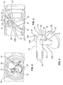
- FIG 1 is a perspective illustration of an embodiment of an exhaust-gas turbocharger 4 according to the invention, which comprises a charger housing 2.
- the charger housing 2 is assembled from a turbine housing 19, a bearing housing 20 and a compressor housing 21, which are in each case connected to one another as shown in detail in Figure 1 .
- the exhaust-gas turbocharger 4 is equipped with a control arrangement 1, which may be either a wastegate valve arrangement or a regulating valve arrangement.
- Figure 1 illustrates a wastegate valve arrangement as a control arrangement 1.
- Said control arrangement 1 accordingly has a spindle 15 which has a first end region 24 which is visible in Figure 4 and which is arranged outside the (in this case) turbine housing 19 and to which an outer lever 14 is fixed.
- the spindle 15 furthermore has a second end region 25 arranged within the turbine housing 19.
- a control means 18 in the form of a valve disk of the control arrangement 1 is illustrated, said control means being connected to the spindle 15.
- the exhaust-gas turbocharger 4 as per the illustration in Figure 1 furthermore has an actuating device 17 which comprises an actuator 22 which, in the embodiment illustrated in Figure 1 , is fixed to the compressor housing 21 by way of a bracket 3.
- the actuator 22 may be in the form of a pneumatic control capsule or in the form of an electric actuator (E-actuator).
- E-actuator electric actuator
- the actuator 22 has a regulating rod 13 which is connected to the outer lever 14 by way of a connecting piece 23.
- the lever 14 is pivoted, and thus the spindle 15 and the valve disk 18 fastened thereto are pivoted in order to open and close a wastegate valve opening that is not visible in Figure 1 .
- valve disk 18 of the control arrangement 1 is connected to the spindle 15, said valve disk and spindle being manufactured as separate components, wherein the spindle 15 is connected by way of its second end region 25 to the valve disk 18 by way of a connecting means 26.
- the connecting means 26 has a fork-shaped fixing region 27 which is arranged, preferably integrally, on the valve disk 18, which fixing region, in the state in which it is fixed to the spindle 15, engages around the end region 25 of the spindle 15.
- a welded connection 32 is provided, the weld faces of which are preferably provided between the abovementioned surfaces 28 to 31 and also in the rounded transition region 43 between said surfaces.
- the fixing region 27 has two oppositely arranged fork regions 27A and 27B which bear counterpart surfaces 30 and 31.
- the fork region 27A has a rounded outer surface 27C
- the fork region 27B comprises an oblique surface 27D which is arranged at an angle ⁇ with respect to the surface of the valve disk 18.
- Both fork regions 27A and 27B comprise top surfaces 27E and 27F, respectively, which lie in a plane.
- the surfaces 27D and the surfaces 27F enclose an obtuse angle ⁇ , whereas the angle ⁇ is an acute angle.
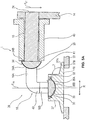
- FIG 5A is an illustration of a further embodiment of the control arrangement 1 according to the invention, in which all elements that correspond to those in Figures 1 to 4 are identified by the same reference signs.
- control arrangement 1 as per the embodiment of Figure 5A likewise has a spindle 15 which is guided by means of a bearing arrangement 40 in the charger housing (not illustrated) and the first end region 24, arranged outside the charger housing, of which is connected to an outer lever 14.
- the bearing arrangement 40 extends over the entire length of the spindle 15, with the exception of the end regions 24 and 25 of the latter, which project out of the bearing arrangement.
- the second end region 25, arranged within the charger housing, is likewise connected, by way of the connecting means 26, to the valve disk 18.
- the connecting means 26 has a multiplicity of components. These components include firstly a spherical segment 34 which has a circular base surface 34B which is connected to the second end region 25.
- the spherical segment 34 has a spherical cap 34A which is adjoined, in the embodiment as per Figure 5A , by an inner lever 16 with two lever sections 16A and 16B.
- the first lever section 16A is connected by way of one lever end 41 to the spherical cap 34A and by way of a second lever end 42 to the second lever section 16B.
- the second lever section 16B is adjoined by a second spherical segment 35.
- Said second spherical segment 35 is connected by way of its circular base surface 35A to the second lever section 16B.
- the second spherical segment 35 also has a spherical cap 35B, which is received entirely in a receiving space 36 of the valve disk 18.
- valve disk 18 and the spindle 15 are separate components which can be connected to one another by way of the connecting means 26 described above.
- the valve disk 18 and the spindle 15 are separate components which can be connected to one another by way of the connecting means 26 described above.
- the valve disk 18 it is possible, in order to improve the sealing action between the valve disk 18 and the valve seats 33, for the valve disk 18 to be held firmly with sealing action against the valve seat 33 during the assembly process, as indicated by the arrow F VS .
- the connection between valve disk 18 and spindle 15 is produced, this being performed in particular by welding. In this way, it is advantageously possible in this embodiment, too, for tolerances to be compensated and a perfected sealing action to be attained.
- the spindle 15, the first spherical segment 34, the inner lever 16 with its two lever sections 16A and 16B in the example, and the second spherical segment 35 to be formed as a unipartite component.
- a second lever section 16B is provided which is of rectilinear form.
- the second spherical segment 35 it would however also be possible for the second spherical segment 35 to directly adjoin the second end 42 of the first lever section 16A.
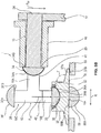
- the embodiment of the control arrangement as per Figure 5B is characterized by the provision of a third lever section 16C which, corresponding to the lever section 16B, in this embodiment branches off at right angles from the first lever section 16A but in the opposite direction to the second section 16B, as can be readily seen from the diagrammatic illustration of Figure 5B .
- the third lever section 16C is equipped with a third spherical segment 35' which is connected by way of its circular base surface 35'A to the free end of the third lever section 16C, for example by way of a welded connection.
- the third spherical segment 35' furthermore has a spherical cap 35'B, wherein the third spherical segment 35' in the particularly preferred embodiment illustrated in Figure 5B is of identical form to the second spherical segment 35.
- the provision of the third lever section 16C with its third spherical segment 35' attached thereto forms a counterweight with respect to the second lever section 16B and the spherical segment 35 attached thereto, which improves the acceleration and vibration characteristics of the control arrangement 1 as per the embodiment of Figure 5B .
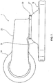
- connection part 37' has a curved outer surface 38. This yields the advantage of a particularly compact design.
- FIGS 8A to 8E show the individual parts of a further embodiment of a control arrangement 43 according to the invention, which is shown in Figure 9 in the assembled state.
- control arrangement 43 as per Figure 8A has a spindle 44 with a cylindrical spindle body 45 which has an outer diameter dA45 which is constant over the entire length of the spindle body 45.
- the spindle body 45 is adjoined, substantially at right angles, by a connecting piece 46, which may be connected integrally to said spindle body or which may likewise be an individual part which can be connected, in particular by way of a welded connection, to the spindle body 45.
- Figure 8B shows a valve disk 48 which can be connected to said spherical segment 47.
- the valve disk 48 has a receiving recess 48B which is arranged in a spherical cap 48A and which has an internal diameter DI48B.
- Said internal diameter DI48B corresponds to the external diameter DA47, or is configured to be slightly larger than the outer diameter DA47.
- Figure 8C shows a bushing 50 that can be inserted into the spindle 44.
- the bushing 50 has an internal diameter DI50 and has an external diameter DA50 which is constant over the entire length of the bushing 50.
- the bushing 50 has a passage recess 51, the length L51 and width B51 of which are adapted to the dimensioning of the connecting piece 46 such that, when the spindle 44 is inserted, said connecting piece can project through the passage recess 51, as can be seen from the illustration of Figure 9 .
- the bushing 50 furthermore has a tongue 55 which has a length L55 slightly shorter than the length L51 and which, together with an opposite housing region 56 of the bushing 50, delimits a slot 52. As shown in Figure 8C , the opening angle of said slot 52 is, owing to the tongue 55, smaller than the opening angle of the passage recess 51.
- Figure 8E shows a lever 53 which is an outer lever, which means that it is arranged outside the turbine housing when the control arrangement 43 is installed in the turbine housing.
- Said outer lever 53 may self-evidently be adapted to the respective dimensioning and the respective usage of the control arrangement 43, but is of conventional design with regard to its geometry and dimensioning.
- the bushing 50 is arranged in a turbine housing recess, wherein said bushing is preferably pressed into said recess. Subsequently, the spindle 44 is inserted into the bushing 50, such that the connecting piece 46 projects out of the bushing 50, as can be seen in Figure 9 .
- the intermediate piece 49 is pushed onto the end 54 and connected, preferably welded, thereto.
- an angle between the outer lever 53 and the spindle 44 relative to the valve disk 48 is adjusted, and the lever 53 is fixed, preferably welded, to the cylindrical spindle body 45 of the spindle 44.
- the lever 53 is pulled on in the direction of the valve disk 48, as has already been discussed with reference to Figure 5 .
- the valve disk 48 is finally connected, preferably welded, to the spherical segment 47, for which purpose the spherical segment 47 is inserted into the receiving recess 48B.
- a welded connection is a particularly preferred embodiment.
- Figure 10 corresponds to the illustration of the spindle as per Figure 8A , such that with regard to the features of the spindle 44, reference may be made to the above description of Figure 8A .
- a region of wear is schematically symbolized by the surface region FB, which extends at least substantially over the entire length of the spindle body 45.
- Tests carried out within the context of the invention have shown that said region of wear VB, which as stated extends substantially over the entire length of the spindle body 45, arises during operation but surprisingly has no influence on the sealing action of the sealing seat between the valve disk 18 and the valve seat 33. This is the case in particular if the region of wear VB is oriented at least substantially parallel to the valve disk surface.
- Figure 11 shows two curves K1 and K2 illustrated in an X-Y coordinate system, with the acceleration plotted on the X axis and the amplitude plotted on the Y axis.
- the curve K1 represents a valve disk according to the prior art, for example WO 2014/011468 A1
- the curve K2 represents an embodiment of a control arrangement according to the invention.
- the comparison between the two curves K1 and K2 clearly shows that the control arrangement according to the invention exhibits smoother acceleration and vibration characteristics than the control arrangement according to the prior art, wherein said smoother vibration characteristics have an advantageous effect on the function of the control arrangement according to the invention.
Landscapes
- Engineering & Computer Science (AREA)
- General Engineering & Computer Science (AREA)
- Mechanical Engineering (AREA)
- Chemical & Material Sciences (AREA)
- Combustion & Propulsion (AREA)
- Supercharger (AREA)
Abstract
Description
- The invention relates to a control arrangement of an exhaust-gas turbocharger as per the preamble of claim 1.
- A control arrangement of said type is known from
DE 10 2009 048 125 A1 - It is therefore an object of the present invention to provide a control arrangement of the type indicated in the preamble of claim 1 which permits an improved sealing action between valve disk and valve seat of the control arrangement.
- This object is achieved by the features of claim 1.
- By contrast to the prior art, it is provided according to the invention that the valve disk and the spindle are separate components. In this way, in order to improve the sealing action between valve disk and valve seat, the valve disk can, during assembly, be held firmly with sealing action against the valve seat and connected, in particular welded, to the spindle in this state. In this way, it is advantageously possible for tolerances to be compensated and a perfected sealing action to be attained.
- The dependent claims contain advantageous developments of the invention.
- In a particularly preferred embodiment, the connecting means preferably has a multiplicity of components, by means of which it is possible to carry out adaptations to particular installation situations or configurations of the control arrangements of the turbocharger.
- In particular, it is possible for the connecting means to comprise a spherical segment which can be connected to the second end region of the spindle which is arranged within the bearing housing.
- In this embodiment, the connecting means furthermore advantageously has an inner lever by means of which the spherical segment and thus the second end region, arranged within the bearing housing, of the spindle can be connected to the valve disk.
- In a further particularly preferred embodiment, the inner lever may comprise two lever sections. In this case, one of the lever sections may be of cranked form, preferably so as to be cranked by 90°, and may either directly adjoin a second spherical segment, which is connectable to the valve disk, or be connected to said second spherical segment via a second lever section.
- The provision of a second spherical segment which can be inserted into a receiving recess, of complementary form, of the valve disk, yields the advantage that the assembly process is particularly straightforward even in the presence of relatively large tolerances, and the achievable sealing action at the valve seat can be further improved.
- It is furthermore an object of the present invention to specify a method for assembling a control arrangement of an exhaust-gas turbocharger, by means of which method it is possible to achieve an improved sealing action between valve disk and valve seat of the control arrangement, which method is furthermore technically more straightforward to carry out.
- This object is achieved by the features of
claim 16. - According to the invention, the individual parts of the control arrangement are initially produced in the form of a bushing, a spindle, a valve disk, an intermediate piece and an outer lever.
- For the assembly of the control arrangement, it is initially the case that the bushing is inserted, in particular pressed, into a recess of the turbine housing.
- After the insertion of the bushing, the spindle is inserted into the bushing.
- In the subsequent step, the valve disk is placed against a wastegate opening of the turbine housing, and an intermediate piece is mounted onto an end of the spindle. The mounted intermediate piece is connected, in particular welded, to the end of the spindle, wherein, in a particularly preferred embodiment, a spot weld is initially formed, and then those further regions between the intermediate piece and the end of the spindle that are accessible to the welding device are filled with further welds.
- After said connection of the intermediate piece to the spindle, an angle between the outer lever and the spindle relative to the valve disk is adjusted and the lever is fastened, in particular welded, to the spindle.
- The lever is thereupon pulled on in the closing direction of the valve disk, wherein, in other words, the valve disk is pressed against the valve seat. In this state, in the final method step, the valve disk is connected, in particular welded, to a spherical segment of the spindle, wherein in turn, in a particularly preferred embodiment, a spot weld is initially formed before further welding is performed.
- Further details, advantages and features of the present invention can be found in the following description of exemplary embodiments with reference to the drawing, in which:
-
Figure 1 shows a perspective sectional illustration of an embodiment of an exhaust-gas turbocharger according to the invention, -
Figures 2 and 3 show perspective views of the valve disk and of the spindle from different viewing directions. -
Figure 4 shows a perspective illustration of the spindle and of the valve disk, -
Figure 5A shows a sectional illustration of a second embodiment of a control arrangement according to the invention, -
Figure 5B shows a sectional illustration, corresponding toFigure 5A , of an alternative design of the second embodiment of a control arrangement according to the invention, -
Figure 6 shows a front view of a third embodiment of a control arrangement according to the invention, -
Figure 7 shows an illustration, corresponding toFigure 6 , of a further embodiment of the control arrangement according to the invention, -
Figures 8A-8E show individual components of a further embodiment of the control arrangement according to the invention, -
Figure 9 shows the control arrangement composed of the components as perFigures 8A to 8E in the fully assembled state, -
Figure 10 shows an illustration, corresponding toFigure 8A , of a spindle with a closing region illustrated in schematically simplified form, and -
Figure 11 shows a coordinate system with two curves for illustrating the acceleration behavior of a control arrangement according to the prior art and of an embodiment of the control arrangement according to the invention. -
Figure 1 is a perspective illustration of an embodiment of an exhaust-gas turbocharger 4 according to the invention, which comprises a charger housing 2. The charger housing 2 is assembled from aturbine housing 19, abearing housing 20 and acompressor housing 21, which are in each case connected to one another as shown in detail inFigure 1 . - The exhaust-gas turbocharger 4 is equipped with a control arrangement 1, which may be either a wastegate valve arrangement or a regulating valve arrangement.
Figure 1 illustrates a wastegate valve arrangement as a control arrangement 1. Said control arrangement 1 accordingly has aspindle 15 which has afirst end region 24 which is visible inFigure 4 and which is arranged outside the (in this case)turbine housing 19 and to which anouter lever 14 is fixed. Thespindle 15 furthermore has asecond end region 25 arranged within theturbine housing 19. Furthermore, in the embodiment illustrated inFigure 1 , a control means 18 in the form of a valve disk of the control arrangement 1 is illustrated, said control means being connected to thespindle 15. - The exhaust-gas turbocharger 4 as per the illustration in
Figure 1 furthermore has anactuating device 17 which comprises anactuator 22 which, in the embodiment illustrated inFigure 1 , is fixed to thecompressor housing 21 by way of a bracket 3. Theactuator 22 may be in the form of a pneumatic control capsule or in the form of an electric actuator (E-actuator). As shown inFigure 1 , theactuator 22 has a regulatingrod 13 which is connected to theouter lever 14 by way of a connectingpiece 23. When the regulatingrod 13 is moved longitudinally by theactuator 22, thelever 14 is pivoted, and thus thespindle 15 and thevalve disk 18 fastened thereto are pivoted in order to open and close a wastegate valve opening that is not visible inFigure 1 . - As can be seen from a juxtaposition of
Figures 2 to 4 , thevalve disk 18 of the control arrangement 1 is connected to thespindle 15, said valve disk and spindle being manufactured as separate components, wherein thespindle 15 is connected by way of itssecond end region 25 to thevalve disk 18 by way of aconnecting means 26. - As is furthermore shown in
Figures 2 to 4 , the connectingmeans 26 has a fork-shaped fixing region 27 which is arranged, preferably integrally, on thevalve disk 18, which fixing region, in the state in which it is fixed to thespindle 15, engages around theend region 25 of thespindle 15. - As is shown in this regard in
Figure 3 , it is the case in the particularly preferred embodiment in the figures that thesecond end region 25 is equipped with twoflattened abutment surfaces 28 and 29 that are oriented parallel. The fork-shaped fixing region 27 is equipped with correspondingly formedcounterpart surfaces abutment surfaces 28 and 29 in the assembled state. - It is furthermore the case in the particularly preferred embodiment that, in the region indicated by the
arrow 32, awelded connection 32 is provided, the weld faces of which are preferably provided between theabovementioned surfaces 28 to 31 and also in therounded transition region 43 between said surfaces. - As can also be seen from a juxtaposition of
Figures 3 and 4 , thefixing region 27 has two oppositely arrangedfork regions counterpart surfaces fork region 27A has a roundedouter surface 27C, whereas thefork region 27B comprises anoblique surface 27D which is arranged at an angle α with respect to the surface of thevalve disk 18. Bothfork regions top surfaces surfaces 27D and thesurfaces 27F enclose an obtuse angle β, whereas the angle α is an acute angle. - With this refinement, for the assembly of the
valve disk 18 on thespindle 15, it is possible for thevalve disk 18 to be pressed sealingly against thevalve seat 33 and to be connected, preferably welded, to thespindle 15, in particular to thesecond end region 25 thereof, in this state. As discussed in the introduction, it is possible in this way for tolerances to be compensated and for the desired sealing action betweenvalve disk 18 and sealingseat 33 to be realized. -
Figure 5A is an illustration of a further embodiment of the control arrangement 1 according to the invention, in which all elements that correspond to those inFigures 1 to 4 are identified by the same reference signs. - Accordingly, the control arrangement 1 as per the embodiment of
Figure 5A likewise has aspindle 15 which is guided by means of abearing arrangement 40 in the charger housing (not illustrated) and thefirst end region 24, arranged outside the charger housing, of which is connected to anouter lever 14. As shown inFigure 5A , it is the case in this embodiment that thebearing arrangement 40 extends over the entire length of thespindle 15, with the exception of theend regions - In the embodiment illustrated in
Figure 5A , thesecond end region 25, arranged within the charger housing, is likewise connected, by way of theconnecting means 26, to thevalve disk 18. However, in the embodiment illustrated inFigure 5A , the connectingmeans 26 has a multiplicity of components. These components include firstly aspherical segment 34 which has acircular base surface 34B which is connected to thesecond end region 25. - Furthermore, the
spherical segment 34 has aspherical cap 34A which is adjoined, in the embodiment as perFigure 5A , by aninner lever 16 with twolever sections first lever section 16A is connected by way of onelever end 41 to thespherical cap 34A and by way of asecond lever end 42 to thesecond lever section 16B. - In the embodiment of
Figure 5A , thesecond lever section 16B is adjoined by a secondspherical segment 35. Said secondspherical segment 35 is connected by way of itscircular base surface 35A to thesecond lever section 16B. The secondspherical segment 35 also has aspherical cap 35B, which is received entirely in a receivingspace 36 of thevalve disk 18. - In the embodiment illustrated in
Figure 5A , the receivingspace 36 is arranged in acylindrical connection part 37 of thevalve disk 18. Theconnection part 37 has avalve disk region 37A which is widened in a radial direction R, which adjoins theconnection part 37 at an obtuse angle γ, and which has acontact surface 37B which lies against thevalve seat 33. - This configuration yields a particularly stable embodiment of the
valve disk 18, which, even with fine dimensioning and associated low weight, yields surprisingly low inertial forces. Here, tests carried out within the context of the invention have shown that, despite very slender dimensioning, reduced wear of the control arrangement according to the invention is attained, which is surprising in particular as said control arrangement is used in extremely critical temperature ranges of over 900° and under alternating gas pressures, which is associated with high loading. - Furthermore,
Figure 5A shows, by way of thereference sign 32, a further element of the connectingmeans 26, which may for example be a welded connection, preferably a laser-welded connection, by means of which thespherical segment 35 can be connected to thevalve disk 18. - This means that, in the case of the embodiment of the control arrangement 1 as per
Figure 5A , too, thevalve disk 18 and thespindle 15 are separate components which can be connected to one another by way of the connecting means 26 described above. Thus, in this embodiment, too, it is possible, in order to improve the sealing action between thevalve disk 18 and the valve seats 33, for thevalve disk 18 to be held firmly with sealing action against thevalve seat 33 during the assembly process, as indicated by the arrow FVS. In this state, by virtue of the secondspherical segment 35 being fixed in the receivingspace 36, the connection betweenvalve disk 18 andspindle 15 is produced, this being performed in particular by welding. In this way, it is advantageously possible in this embodiment, too, for tolerances to be compensated and a perfected sealing action to be attained. - In principle, it is possible for the
spindle 15, the firstspherical segment 34, theinner lever 16 with its twolever sections spherical segment 35 to be formed as a unipartite component. - It is however also possible for the stated elements to each be formed as individual components, which can be connected, in particular welded, to one another during the course of assembly.
- It is additionally pointed out that the arrow FST symbolizes the direction of the occurring stresses and the resulting tolerances, which can be compensated by way of the above-discussed assembly option for attaining a perfected sealing action.
- In the case of the embodiment illustrated in
Figure 5A , thefirst lever section 16A is, owing to the arrangement of thevalve disk 18, of cranked form, with a particularly preferred angle of the cranked form being 90°. - Furthermore, a
second lever section 16B is provided which is of rectilinear form. With a corresponding arrangement, it would however also be possible for the secondspherical segment 35 to directly adjoin thesecond end 42 of thefirst lever section 16A. - Furthermore, it would likewise be possible, with a corresponding orientation of the
valve disk 18, for thefirst section 16A to be formed without a cranked configuration. -
Figure 5B shows an alternative design of the second embodiment as perFigure 5A . Therefore, all the features that correspond to the embodiment as perFigure 5A are denoted by the same reference signs, such that in this regard, reference may be made to the description above. - The embodiment of the control arrangement as per
Figure 5B is characterized by the provision of athird lever section 16C which, corresponding to thelever section 16B, in this embodiment branches off at right angles from thefirst lever section 16A but in the opposite direction to thesecond section 16B, as can be readily seen from the diagrammatic illustration ofFigure 5B . - At its free end, the
third lever section 16C is equipped with a third spherical segment 35' which is connected by way of its circular base surface 35'A to the free end of thethird lever section 16C, for example by way of a welded connection. The third spherical segment 35' furthermore has a spherical cap 35'B, wherein the third spherical segment 35' in the particularly preferred embodiment illustrated inFigure 5B is of identical form to the secondspherical segment 35. Accordingly, the provision of thethird lever section 16C with its third spherical segment 35' attached thereto, forms a counterweight with respect to thesecond lever section 16B and thespherical segment 35 attached thereto, which improves the acceleration and vibration characteristics of the control arrangement 1 as per the embodiment ofFigure 5B . - Furthermore, the control arrangement 1 as per the embodiment of
Figure 5B has a fourthspherical segment 58 which has aspherical cap 58A which projects into the wastegate opening when thevalve disk 18, in the sealing position illustrated inFigure 5B , lies against thevalve seat 33. For this purpose, thespherical segment 58 is fastened, for example by way of a welded connection, preferably centrally by way of itscircular base surface 58B to an in this casecentral surface region 18A of thevalve disk 18. The provision of thespherical segment 58 furthermore increases the sealing action of the sealing seat between thevalve disk 18 and thevalve seat 33, and likewise improves the vibration characteristics, in particular under the action of pressure shock loads on thevalve disk 18. - The embodiment in
Figure 6 corresponds to that ofFigure 5 , such that reference may be made to the description ofFigure 5 . - In the embodiment illustrated in
Figure 6 , however, the connection part 37' has a curvedouter surface 38. This yields the advantage of a particularly compact design. - The embodiment in
Figure 7 in turn corresponds to that ofFigure 5 , such that in this regard, too, reference may be made to the embodiment as perFigure 5 . - In the embodiment as per
Figure 7 , however, there is provided, as a further feature, acontact collar 39 which lies against the connection region 37'. -
Figures 8A to 8E show the individual parts of a further embodiment of acontrol arrangement 43 according to the invention, which is shown inFigure 9 in the assembled state. - Accordingly, the
control arrangement 43 as perFigure 8A has aspindle 44 with acylindrical spindle body 45 which has an outer diameter dA45 which is constant over the entire length of thespindle body 45. - In the region of an
end 54 of thespindle body 55 which, in the installed state, is an inner end of thespindle 44, thespindle body 45 is adjoined, substantially at right angles, by a connectingpiece 46, which may be connected integrally to said spindle body or which may likewise be an individual part which can be connected, in particular by way of a welded connection, to thespindle body 45. - The connecting
piece 46 bears, at its free end, aspherical segment 47 with an external diameter DA47. -
Figure 8B shows avalve disk 48 which can be connected to saidspherical segment 47. For the connection, thevalve disk 48 has a receivingrecess 48B which is arranged in aspherical cap 48A and which has an internal diameter DI48B. Said internal diameter DI48B corresponds to the external diameter DA47, or is configured to be slightly larger than the outer diameter DA47. -
Figure 8C shows abushing 50 that can be inserted into thespindle 44. For this purpose, thebushing 50 has an internal diameter DI50 and has an external diameter DA50 which is constant over the entire length of thebushing 50. - As shown in
Figure 8C , thebushing 50 has apassage recess 51, the length L51 and width B51 of which are adapted to the dimensioning of the connectingpiece 46 such that, when thespindle 44 is inserted, said connecting piece can project through thepassage recess 51, as can be seen from the illustration ofFigure 9 . - The
bushing 50 furthermore has atongue 55 which has a length L55 slightly shorter than the length L51 and which, together with anopposite housing region 56 of thebushing 50, delimits aslot 52. As shown inFigure 8C , the opening angle of saidslot 52 is, owing to thetongue 55, smaller than the opening angle of thepassage recess 51. - Finally,
Figure 8E shows alever 53 which is an outer lever, which means that it is arranged outside the turbine housing when thecontrol arrangement 43 is installed in the turbine housing. Saidouter lever 53 may self-evidently be adapted to the respective dimensioning and the respective usage of thecontrol arrangement 43, but is of conventional design with regard to its geometry and dimensioning. These explanations show that, in this embodiment, the connectingpiece 46 and thespherical segment 47 form a connectingmeans 57. - A possible method for the assembly of a control arrangement of an exhaust-gas turbocharger 4 will be discussed below on the basis of the embodiment of the
control arrangement 43 as perFigures 8A to 8E and 9 . Accordingly, the individual constituent parts as perFigures 8A to 8E are firstly provided. - In a first assembly step, the
bushing 50 is arranged in a turbine housing recess, wherein said bushing is preferably pressed into said recess. Subsequently, thespindle 44 is inserted into thebushing 50, such that the connectingpiece 46 projects out of thebushing 50, as can be seen inFigure 9 . - The
valve disk 48 is subsequently mounted onto a wastegate opening of thevalve seat 33, as can be seen for example from the illustration ofFigure 5 . - Subsequently, the
intermediate piece 49 is pushed onto theend 54 and connected, preferably welded, thereto. - In the subsequent method step, an angle between the
outer lever 53 and thespindle 44 relative to thevalve disk 48 is adjusted, and thelever 53 is fixed, preferably welded, to thecylindrical spindle body 45 of thespindle 44. In this state, thelever 53 is pulled on in the direction of thevalve disk 48, as has already been discussed with reference toFigure 5 . In this state, with thelever 43 being pulled on, thevalve disk 48 is finally connected, preferably welded, to thespherical segment 47, for which purpose thespherical segment 47 is inserted into the receivingrecess 48B. In the case of this connection, too, a welded connection is a particularly preferred embodiment. -
Figure 10 corresponds to the illustration of the spindle as perFigure 8A , such that with regard to the features of thespindle 44, reference may be made to the above description ofFigure 8A . InFigure 10 , a region of wear is schematically symbolized by the surface region FB, which extends at least substantially over the entire length of thespindle body 45. Tests carried out within the context of the invention have shown that said region of wear VB, which as stated extends substantially over the entire length of thespindle body 45, arises during operation but surprisingly has no influence on the sealing action of the sealing seat between thevalve disk 18 and thevalve seat 33. This is the case in particular if the region of wear VB is oriented at least substantially parallel to the valve disk surface. -
Figure 11 shows two curves K1 and K2 illustrated in an X-Y coordinate system, with the acceleration plotted on the X axis and the amplitude plotted on the Y axis. Here, the curve K1 represents a valve disk according to the prior art, for exampleWO 2014/011468 A1 , whereas the curve K2 represents an embodiment of a control arrangement according to the invention. The comparison between the two curves K1 and K2 clearly shows that the control arrangement according to the invention exhibits smoother acceleration and vibration characteristics than the control arrangement according to the prior art, wherein said smoother vibration characteristics have an advantageous effect on the function of the control arrangement according to the invention. - In addition to the above written disclosure of the invention, reference is hereby explicitly made to the illustrative presentation thereof in
Figures 1 to 11 . - Although the present invention is defined in the attached claims, it is to be understood that the invention can alternatively also be defined in accordance with the following embodiments:
- 1. A control arrangement (1) of an exhaust-gas turbocharger (4) which has a charger housing (2),
- having a spindle (15)
- which has a first end region (24) arranged outside the charger housing (2) and
- which has a second end region (25) arranged within the charger housing (2);
- having a valve disk (18) which is connected to the spindle (15) and which interacts with a valve seat (33), wherein
- the valve disk (18) and the spindle (15) are separate components, and
- the spindle (15) is connected by way of its second end region (25) to the valve disk (18) by means of a connecting means (26) after alignment of the valve disk (18) on the valve seat (33).
- having a spindle (15)
- 2. The control arrangement of embodiment 1, wherein the connecting means (26) has a fork-shaped fixing region (27) arranged on the valve disk (18), which fixing region engages around the second end region (25) of the spindle (15).
- 3. The control arrangement of embodiment 2, wherein the second end region (25) has flattened abutment surfaces (28, 29) which bear against counterpart surfaces (30, 31) of the fork-shaped fixing region (27) and are preferably welded to one another.
- 4. The control arrangement of embodiment 1, wherein the connecting means (26) has a first spherical segment (34) which is connected to the second end region (25).
- 5. The control arrangement of embodiment 4, wherein the second end region (25) is connected to a circular base surface (34B) of the first spherical segment (34).
- 6. The control arrangement of embodiment 4 or 5, wherein the first spherical segment (34) furthermore has a spherical cap (34A) which is connected to a first end (41) of an inner lever (16).
- 7. The control arrangement of
embodiment 6, wherein the inner lever (16) has a first lever section (16A) which comprises the first lever end (41) and which is connected to a second lever section (16B) via a second lever end (42). - 8. The control arrangement of embodiment 7, wherein the first lever section (16A) is cranked by approximately 90°, preferably exactly 90°.
- 9. The control arrangement of any one of the embodiments 4 to 7, wherein the connecting means (26) furthermore has a second spherical segment (35) which is connected at a base surface (35A) to the inner lever (16) and which has a spherical cap (35B) arranged in a receiving space (36) of the valve disk (18).
- 10. The control arrangement of
embodiment 9, wherein the receiving space (36) is arranged in a cylindrical connection part (37) of the valve disk (18). - 11. The control arrangement of any one of the embodiments 4 to 10, wherein the first spherical segment (34), the inner lever (16) and the second spherical segment (35) are separate components which are connected, preferably welded, to one another.
- 12. The control arrangement of any one of the embodiments 4 to 10, wherein the first spherical segment (34), the inner lever (16) and the second spherical segment (35) are formed as a unipartite component.
- 13. The control arrangement of any one of the
embodiments 10 to 12, wherein the cylindrical connection part (37) and the valve disk (18) are formed in one piece. - 14. The control arrangement of any one of the embodiments 4 to 13, wherein the spindle (15) and the connecting means (26) are formed as a unipartite component.
- 15. The control arrangement of any one of the embodiments 4 to 13, wherein the spindle (15) and the connecting means (26) are separate components which are connected, preferably welded, to one another.
- 16. A method for assembling a control arrangement (43) of an exhaust-gas turbocharger (4), having the following method steps:
- a. inserting a bushing (50) into a turbine housing recess;
- b. inserting a spindle (44) into the bushing (50);
- c. placing a valve disk (48) against a wastegate opening of the turbine housing;
- d. mounting an intermediate piece (49) onto one end (54) of the spindle (44);
- e. connecting, preferably welding, the intermediate piece (49) to the end (54) of the spindle (44);
- f. adjusting an angle between an outer lever (53) and the spindle (44) relative to the valve disk (48);
- g. fastening, preferably welding, the lever (53) to the spindle (44);
- h. pulling on the lever (53) in the closing direction of the valve disk (48);
- i. connecting, preferably welding, the valve disk (48) to a spherical segment (47) of the spindle (44).
-
- 1
- Control arrangement
- 2
- Charger housing
- 3
- Bracket
- 4
- Exhaust-gas turbocharger
- 5
- Housing upper part
- 6
- Housing lower part
- 7
- Actuator housing
- 8
- Spring
- 9
- Turbine wheel
- 10
- Rotor shaft
- 11
- Compressor wheel
- 12
- Journal
- 13
- Regulating rod
- 14
- Outer lever
- 15
- Spindle
- 16
- Inner lever
- 16A, 16B, 16C
- First, second and third lever section
- 17
- Operating device
- 18
- Control means (valve disk)
- 18A
- Preferably central surface region
- 19
- Compressor housing
- 20
- Bearing housing
- 21
- Compressor housing
- 22, 23
- Bearing
- 24, 25
- End region
- 26
- Connecting means
- 27
- Fixing region
- 27A, 27B
- Fork regions
- 27C
- Outer surface
- 27D, 27F
- Oblique surfaces
- 27E
- Top surfaces
- 28, 29, 30, 31
- Abutment surfaces or counterpart surfaces
- 32
- Welded connection
- 33
- Valve seat
- 34
- First spherical segment
- 34A
- Spherical cap
- 34B
- Circular base surface
- 35
- Second spherical element
- 35A
- Circular base surface
- 35B
- Spherical cap
- 35'
- Third spherical segment
- 35'A
- Spherical cap
- 35'B
- Circular base surface
- 36
- Receiving space
- 37, 37'
- Connection region
- 37A
- Valve disk region
- 37B
- Contact surface
- 38
- Outer surface
- 39
- Contact collar
- 40
- Bearing arrangement
- 41
- First shaft end
- 42
- Second shaft end
- 43
- Control arrangement
- 44
- Spindle
- 45
- Cylindrical spindle body
- 46
- Connecting piece
- 47
- Spherical segment
- 48
- Valve disk
- 48A
- Spherical cap
- 48B
- Receiving recess
- 49
- Intermediate piece
- 50
- Bushing
- 51
- Passage recess
- 52
- Slot
- 53
- Outer lever
- 54
- End of the spindle body
- 55
- Tongue
- 56
- Housing region
- 57
- Connecting means
- 58
- Fourth spherical element
- 58A
- Spherical cap
- 58B
- Circular base surface
- L51, L55
- Lengths
- B51
- Width
- FVS
- Force on the sealing seat
- FST
- Loading direction
- FB
- Surface region
- VB
- Wear region
- K1, K2
- Curves
- α, β, γ
- Angles
- dA45, dA47, DI48B, DI49, dA49, dA50, DI50
- Diameter values
Claims (15)
- A method for assembling a control arrangement (1) of an exhaust-gas turbocharger (4), the method having the following method steps:providing a turbine housing (19), a valve disk (18) and a spindle (15), wherein the spindle (15) and the valve disk (18) are separate components;mounting the spindle in the turbine housing (19);placing the valve disk (18) onto a valve seat (33) of a wastegate opening;holding the valve disk (18) firmly with sealing action against a valve seat (33);welding, the valve disk (18) to the spindle (15) in this state.
- The method of claim 1 further comprising the step of providing an outer lever (14), adjusting an angle between the outer lever (14) and the spindle (15) and fastening, preferably welding, the outer lever (14) to the spindle (15).
- The method of claim 2 further comprising pulling on the outer lever (14) in a closing direction of the valve disk (18) to hold the valve disk (18) firmly with sealing action against the valve seat (33).
- The method of any one of the preceding claims further comprising inserting a bushing into a turbine housing recess, wherein, when mounting the spindle (15) in the turbine housing (19), the spindle (15) is inserted into the bushing.
- The method of any one of the preceding claims, wherein the spindle (15) comprises a connecting means (26).
- The method of claim 5, wherein the spindle (15) is connected to the valve disk (18) by way of the connecting means (26).
- The method of claim 5 or claim 6, wherein the spindle (15) and the connecting means (26) are formed as a unipartite component.
- The method of claim 5 or claim 6, wherein the spindle (15) and the connecting means (26) are formed as individual components that are connected, in particular welded, to one another.
- The method of any one of claims 5 to 8, wherein the connecting means (26) comprises a spherical segment (35) that is received in a receiving space (36) of the valve disk (18), and, wherein connecting the valve disk (18) to the spindle (15) comprises connecting, preferably welding, the spherical segment (35) to the valve disk (18).
- The method of claim 9, wherein the receiving space (36) is arranged in a connection part (37; 37') of the valve disk (18).
- The method of claim 10, wherein the connection part is a cylindrical connection part (37) having a valve disk region (37A) which is widened in a radial direction and which adjoins the connection part (37) at an obtuse angle (γ), and which has a contact surface (37B) which lies against the valve seat (33).
- The method of claim 10, wherein the connection part (37') has a curved outer surface (38).
- The method of any one of claims 10 to 12, further comprising providing a contact collar (39) and lying the contact collar (39) against the connection part (37').
- The method of any one of claims 5 to 13, wherein the connecting means (26) comprises an inner lever (16), preferably, wherein the inner lever (16) comprises first and second lever sections (16A, 16B).
- The method of claim 14, when dependent on claim 9, wherein the spherical segment (35) is arranged at an end of the second lever section (16B).
Applications Claiming Priority (4)
| Application Number | Priority Date | Filing Date | Title |
|---|---|---|---|
| DE202014003918.6U DE202014003918U1 (en) | 2014-05-08 | 2014-05-08 | Stellanordnung an exhaust gas turbocharger |
| DE202014007538.7U DE202014007538U1 (en) | 2014-09-17 | 2014-09-17 | Stellanordnung an exhaust gas turbocharger |
| PCT/US2015/029138 WO2015171541A1 (en) | 2014-05-08 | 2015-05-05 | Control arrangement of an exhaust-gas turbocharger |
| EP15722640.8A EP3102804B1 (en) | 2014-05-08 | 2015-05-05 | Method for assembling a control arrangement of an exhaust-gas turbocharger |
Related Parent Applications (2)
| Application Number | Title | Priority Date | Filing Date |
|---|---|---|---|
| EP15722640.8A Division-Into EP3102804B1 (en) | 2014-05-08 | 2015-05-05 | Method for assembling a control arrangement of an exhaust-gas turbocharger |
| EP15722640.8A Division EP3102804B1 (en) | 2014-05-08 | 2015-05-05 | Method for assembling a control arrangement of an exhaust-gas turbocharger |
Publications (2)
| Publication Number | Publication Date |
|---|---|
| EP3382177A1 true EP3382177A1 (en) | 2018-10-03 |
| EP3382177B1 EP3382177B1 (en) | 2021-04-07 |
Family
ID=53177903
Family Applications (2)
| Application Number | Title | Priority Date | Filing Date |
|---|---|---|---|
| EP18173594.5A Active EP3382177B1 (en) | 2014-05-08 | 2015-05-05 | Method for assembling a control arrangement of an exhaust-gas turbocharger |
| EP15722640.8A Active EP3102804B1 (en) | 2014-05-08 | 2015-05-05 | Method for assembling a control arrangement of an exhaust-gas turbocharger |
Family Applications After (1)
| Application Number | Title | Priority Date | Filing Date |
|---|---|---|---|
| EP15722640.8A Active EP3102804B1 (en) | 2014-05-08 | 2015-05-05 | Method for assembling a control arrangement of an exhaust-gas turbocharger |
Country Status (6)
| Country | Link |
|---|---|
| US (1) | US10487724B2 (en) |
| EP (2) | EP3382177B1 (en) |
| KR (2) | KR102280198B1 (en) |
| CN (1) | CN106103938B (en) |
| CA (1) | CA2952169A1 (en) |
| WO (1) | WO2015171541A1 (en) |
Families Citing this family (12)
| Publication number | Priority date | Publication date | Assignee | Title |
|---|---|---|---|---|
| US10646970B2 (en) * | 2014-05-08 | 2020-05-12 | Borgwarner Inc. | Method for assembling control arrangement of an exhaust-gas turbocharger |
| EP3382177B1 (en) * | 2014-05-08 | 2021-04-07 | Borgwarner Inc. | Method for assembling a control arrangement of an exhaust-gas turbocharger |
| US10344666B2 (en) | 2014-09-01 | 2019-07-09 | Garrett Transportation I Inc. | Turbine wastegate |
| DE102015016586A1 (en) * | 2015-12-19 | 2017-06-22 | Daimler Ag | Valve device for a turbine of an exhaust gas turbocharger |
| US10215088B2 (en) * | 2016-07-24 | 2019-02-26 | Garrett Transporation I Inc. | Method of assembling a turbine wastegate assembly |
| US10233827B2 (en) | 2016-07-24 | 2019-03-19 | Garrett Transportation I Inc. | Turbine wastegate |
| US10227916B2 (en) | 2016-07-24 | 2019-03-12 | Garrett Transportation I Inc. | Turbocharger turbine wastegate assembly |
| CN110741144A (en) * | 2017-07-21 | 2020-01-31 | Ihi供应系统国际有限责任公司 | Controlling devices for exhaust gas turbochargers |
| CN209212316U (en) * | 2017-10-11 | 2019-08-06 | 博格华纳公司 | Flap component, turbine and exhaust-driven turbo-charger exhaust-gas turbo charger for turbine |
| EP3779143A4 (en) * | 2018-04-05 | 2021-12-01 | Nittan Valve Co., Ltd. | DISCHARGE VALVE |
| DE202018002846U1 (en) | 2018-06-15 | 2018-06-27 | Borgwarner Inc. | Turbocharger for an internal combustion engine |
| US11255255B2 (en) | 2020-04-10 | 2022-02-22 | Borgwarner Inc. | Turbocharger including a wastegate assembly |
Citations (4)
| Publication number | Priority date | Publication date | Assignee | Title |
|---|---|---|---|---|
| DE4439432C1 (en) * | 1994-11-04 | 1995-11-02 | Daimler Benz Ag | Combustion engine with exhaust valve for catalytic converter |
| DE102006022482A1 (en) * | 2006-05-13 | 2007-12-06 | Bayerische Motoren Werke Ag | Wastegate valve |
| WO2010135104A2 (en) * | 2009-05-18 | 2010-11-25 | Borgwarner Inc. | Turbocharger |
| US20130149114A1 (en) * | 2010-11-09 | 2013-06-13 | Voith Patent Gmbh | Housing for a blade wheel |
Family Cites Families (18)
| Publication number | Priority date | Publication date | Assignee | Title |
|---|---|---|---|---|
| DE2355773C3 (en) * | 1973-11-08 | 1978-06-08 | Honeywell Gmbh, 6000 Frankfurt | Valve |
| US3885771A (en) * | 1974-04-01 | 1975-05-27 | Hans D Baumann | Eccentric rotary plug valve with quick removal trim insert |
| CA1087590A (en) * | 1977-06-30 | 1980-10-14 | James V. Davidson | Eccentric rotary valve with control-improving wing member |
| DE3336879A1 (en) * | 1983-10-11 | 1985-04-25 | Harald 6707 Schifferstadt Hoffmann | Valve-seating device, in particular for rotary cone servo-valves |
| JPH01179132U (en) | 1988-06-10 | 1989-12-22 | ||
| JP3776740B2 (en) * | 2001-03-26 | 2006-05-17 | 三菱重工業株式会社 | Manufacturing method of variable capacity turbine component and structure of component |
| GB0111681D0 (en) * | 2001-05-11 | 2001-07-04 | Holset Engineering Co | Turbo charger with waste gate |
| JP3936928B2 (en) * | 2003-09-26 | 2007-06-27 | 株式会社日立製作所 | Electric throttle device |
| ES2358675T3 (en) * | 2005-03-31 | 2011-05-12 | Cooper-Standard Automotive (Deutschland) Gmbh | EXHAUST GAS RECIRCULATION SYSTEM. |
| GB0710670D0 (en) * | 2007-06-05 | 2007-07-11 | Cummins Turbo Tech Ltd | Turbocharger |
| DE102008011416A1 (en) | 2008-02-27 | 2009-09-10 | Continental Automotive Gmbh | Turbocharger with an actuator for opening and closing a wastegate duct |
| CN101649773B (en) | 2009-08-27 | 2011-10-12 | 芜湖杰锋汽车动力系统有限公司 | Petrol engine supercharger bypass valve |
| DE102010040986A1 (en) * | 2010-04-29 | 2011-11-03 | Bosch Mahle Turbo Systems Gmbh & Co. Kg | Charging device i.e. exhaust-gas turbocharger, has actuating device coupled with regulating device via drive rod that is coupled with regulating device via guide piece, where piece is rotatably mounted in lever at two locations |
| DE102011002918A1 (en) | 2010-05-28 | 2011-12-01 | Bosch Mahle Turbo Systems Gmbh & Co. Kg | Charging device i.e. exhaust gas turbocharger, for motor car, has channel opening experiencing change in direction and flap surface that faces opening regarding flow direction of leaking gas into waste gate valve device |
| JP5987330B2 (en) | 2012-01-31 | 2016-09-07 | 株式会社Ihi | Turbocharger |
| JP5939052B2 (en) * | 2012-06-26 | 2016-06-22 | 株式会社Ihi | Turbocharger |
| JP6283669B2 (en) * | 2012-07-11 | 2018-02-21 | ボーグワーナー インコーポレーテッド | Exhaust gas turbocharger |
| EP3382177B1 (en) * | 2014-05-08 | 2021-04-07 | Borgwarner Inc. | Method for assembling a control arrangement of an exhaust-gas turbocharger |
-
2015
- 2015-05-05 EP EP18173594.5A patent/EP3382177B1/en active Active
- 2015-05-05 CN CN201580010049.8A patent/CN106103938B/en active Active
- 2015-05-05 EP EP15722640.8A patent/EP3102804B1/en active Active
- 2015-05-05 WO PCT/US2015/029138 patent/WO2015171541A1/en not_active Ceased
- 2015-05-05 CA CA2952169A patent/CA2952169A1/en not_active Abandoned
- 2015-05-05 US US15/119,764 patent/US10487724B2/en active Active
- 2015-05-05 KR KR1020217007496A patent/KR102280198B1/en active Active
- 2015-05-05 KR KR1020167023868A patent/KR20170004957A/en not_active Ceased
Patent Citations (4)
| Publication number | Priority date | Publication date | Assignee | Title |
|---|---|---|---|---|
| DE4439432C1 (en) * | 1994-11-04 | 1995-11-02 | Daimler Benz Ag | Combustion engine with exhaust valve for catalytic converter |
| DE102006022482A1 (en) * | 2006-05-13 | 2007-12-06 | Bayerische Motoren Werke Ag | Wastegate valve |
| WO2010135104A2 (en) * | 2009-05-18 | 2010-11-25 | Borgwarner Inc. | Turbocharger |
| US20130149114A1 (en) * | 2010-11-09 | 2013-06-13 | Voith Patent Gmbh | Housing for a blade wheel |
Also Published As
| Publication number | Publication date |
|---|---|
| CN106103938B (en) | 2020-07-28 |
| KR20170004957A (en) | 2017-01-11 |
| KR20210031545A (en) | 2021-03-19 |
| CA2952169A1 (en) | 2015-11-12 |
| EP3102804A1 (en) | 2016-12-14 |
| US10487724B2 (en) | 2019-11-26 |
| KR102280198B1 (en) | 2021-07-22 |
| EP3102804B1 (en) | 2019-01-02 |
| EP3382177B1 (en) | 2021-04-07 |
| WO2015171541A1 (en) | 2015-11-12 |
| CN106103938A (en) | 2016-11-09 |
| US20170058761A1 (en) | 2017-03-02 |
Similar Documents
| Publication | Publication Date | Title |
|---|---|---|
| EP3102804B1 (en) | Method for assembling a control arrangement of an exhaust-gas turbocharger | |
| US9488096B2 (en) | Actuating force transmitting device of an exhaust-gas turbocharger | |
| CN103189613B (en) | Exhaust turbine supercharger | |
| US20160245424A1 (en) | Valve | |
| US20160178028A1 (en) | Charging device | |
| US10087826B2 (en) | Exhaust-gas turbocharger including a charge pressure control lever having barrel-shaped pin | |
| JP6986957B2 (en) | Buffer | |
| US20230343499A1 (en) | Solenoid, solenoid valve, shock absorber, and method formanufacturing a solenoid | |
| US20130187071A1 (en) | Crank | |
| US10646970B2 (en) | Method for assembling control arrangement of an exhaust-gas turbocharger | |
| US9771943B2 (en) | Setting regulating rod length by fixedly attaching a regulating rod to an end piece by application of a weld filler applied thereat through a weld window | |
| CN111173767B (en) | Support system | |
| US20160069253A1 (en) | Control arrangement of an exhaust-gas turbocharger | |
| US20150308448A1 (en) | Exhaust-gas turbocharger | |
| US12085141B2 (en) | Shock absorber | |
| US10001054B2 (en) | Method and device for orienting an actuator of an exhaust-gas turbocharger | |
| US9856752B2 (en) | Exhaust-gas turbocharger and method for manufacturing the same | |
| US8327640B2 (en) | Adjustment device on an exhaust-driven turbocharger | |
| JP2018128369A (en) | Exhaust gas sensor | |
| JP2010110879A (en) | Method for assembling shock absorber | |
| JP6721268B2 (en) | Fuel injection valve | |
| WO2025062656A1 (en) | Valve structure and damping force regulating-type shock absorber | |
| US20210111616A1 (en) | Torque motor housing | |
| WO2025062655A1 (en) | Damping force regulating valve and damping-force-adjusting shock absorber |
Legal Events
| Date | Code | Title | Description |
|---|---|---|---|
| PUAI | Public reference made under article 153(3) epc to a published international application that has entered the european phase |
Free format text: ORIGINAL CODE: 0009012 |
|
| STAA | Information on the status of an ep patent application or granted ep patent |
Free format text: STATUS: REQUEST FOR EXAMINATION WAS MADE |
|
| STAA | Information on the status of an ep patent application or granted ep patent |
Free format text: STATUS: EXAMINATION IS IN PROGRESS |
|
| 17P | Request for examination filed |
Effective date: 20180522 |
|
| AC | Divisional application: reference to earlier application |
Ref document number: 3102804 Country of ref document: EP Kind code of ref document: P |
|
| AK | Designated contracting states |
Kind code of ref document: A1 Designated state(s): AL AT BE BG CH CY CZ DE DK EE ES FI FR GB GR HR HU IE IS IT LI LT LU LV MC MK MT NL NO PL PT RO RS SE SI SK SM TR |
|
| 17Q | First examination report despatched |
Effective date: 20180924 |
|
| GRAP | Despatch of communication of intention to grant a patent |
Free format text: ORIGINAL CODE: EPIDOSNIGR1 |
|
| STAA | Information on the status of an ep patent application or granted ep patent |
Free format text: STATUS: GRANT OF PATENT IS INTENDED |
|
| INTG | Intention to grant announced |
Effective date: 20201023 |
|
| GRAS | Grant fee paid |
Free format text: ORIGINAL CODE: EPIDOSNIGR3 |
|
| GRAA | (expected) grant |
Free format text: ORIGINAL CODE: 0009210 |
|
| STAA | Information on the status of an ep patent application or granted ep patent |
Free format text: STATUS: THE PATENT HAS BEEN GRANTED |
|
| AC | Divisional application: reference to earlier application |
Ref document number: 3102804 Country of ref document: EP Kind code of ref document: P |
|
| AK | Designated contracting states |
Kind code of ref document: B1 Designated state(s): AL AT BE BG CH CY CZ DE DK EE ES FI FR GB GR HR HU IE IS IT LI LT LU LV MC MK MT NL NO PL PT RO RS SE SI SK SM TR |
|
| REG | Reference to a national code |
Ref country code: GB Ref legal event code: FG4D |
|
| REG | Reference to a national code |
Ref country code: AT Ref legal event code: REF Ref document number: 1379965 Country of ref document: AT Kind code of ref document: T Effective date: 20210415 Ref country code: CH Ref legal event code: EP |
|
| REG | Reference to a national code |
Ref country code: DE Ref legal event code: R096 Ref document number: 602015067985 Country of ref document: DE |
|
| REG | Reference to a national code |
Ref country code: IE Ref legal event code: FG4D |
|
| REG | Reference to a national code |
Ref country code: LT Ref legal event code: MG9D |
|
| REG | Reference to a national code |
Ref country code: NL Ref legal event code: MP Effective date: 20210407 Ref country code: AT Ref legal event code: MK05 Ref document number: 1379965 Country of ref document: AT Kind code of ref document: T Effective date: 20210407 |
|
| PG25 | Lapsed in a contracting state [announced via postgrant information from national office to epo] |
Ref country code: NL Free format text: LAPSE BECAUSE OF FAILURE TO SUBMIT A TRANSLATION OF THE DESCRIPTION OR TO PAY THE FEE WITHIN THE PRESCRIBED TIME-LIMIT Effective date: 20210407 Ref country code: BG Free format text: LAPSE BECAUSE OF FAILURE TO SUBMIT A TRANSLATION OF THE DESCRIPTION OR TO PAY THE FEE WITHIN THE PRESCRIBED TIME-LIMIT Effective date: 20210707 Ref country code: AT Free format text: LAPSE BECAUSE OF FAILURE TO SUBMIT A TRANSLATION OF THE DESCRIPTION OR TO PAY THE FEE WITHIN THE PRESCRIBED TIME-LIMIT Effective date: 20210407 Ref country code: FI Free format text: LAPSE BECAUSE OF FAILURE TO SUBMIT A TRANSLATION OF THE DESCRIPTION OR TO PAY THE FEE WITHIN THE PRESCRIBED TIME-LIMIT Effective date: 20210407 Ref country code: HR Free format text: LAPSE BECAUSE OF FAILURE TO SUBMIT A TRANSLATION OF THE DESCRIPTION OR TO PAY THE FEE WITHIN THE PRESCRIBED TIME-LIMIT Effective date: 20210407 Ref country code: LT Free format text: LAPSE BECAUSE OF FAILURE TO SUBMIT A TRANSLATION OF THE DESCRIPTION OR TO PAY THE FEE WITHIN THE PRESCRIBED TIME-LIMIT Effective date: 20210407 |
|
| PG25 | Lapsed in a contracting state [announced via postgrant information from national office to epo] |
Ref country code: GR Free format text: LAPSE BECAUSE OF FAILURE TO SUBMIT A TRANSLATION OF THE DESCRIPTION OR TO PAY THE FEE WITHIN THE PRESCRIBED TIME-LIMIT Effective date: 20210708 Ref country code: IS Free format text: LAPSE BECAUSE OF FAILURE TO SUBMIT A TRANSLATION OF THE DESCRIPTION OR TO PAY THE FEE WITHIN THE PRESCRIBED TIME-LIMIT Effective date: 20210807 Ref country code: NO Free format text: LAPSE BECAUSE OF FAILURE TO SUBMIT A TRANSLATION OF THE DESCRIPTION OR TO PAY THE FEE WITHIN THE PRESCRIBED TIME-LIMIT Effective date: 20210707 Ref country code: PT Free format text: LAPSE BECAUSE OF FAILURE TO SUBMIT A TRANSLATION OF THE DESCRIPTION OR TO PAY THE FEE WITHIN THE PRESCRIBED TIME-LIMIT Effective date: 20210809 Ref country code: PL Free format text: LAPSE BECAUSE OF FAILURE TO SUBMIT A TRANSLATION OF THE DESCRIPTION OR TO PAY THE FEE WITHIN THE PRESCRIBED TIME-LIMIT Effective date: 20210407 Ref country code: LV Free format text: LAPSE BECAUSE OF FAILURE TO SUBMIT A TRANSLATION OF THE DESCRIPTION OR TO PAY THE FEE WITHIN THE PRESCRIBED TIME-LIMIT Effective date: 20210407 Ref country code: RS Free format text: LAPSE BECAUSE OF FAILURE TO SUBMIT A TRANSLATION OF THE DESCRIPTION OR TO PAY THE FEE WITHIN THE PRESCRIBED TIME-LIMIT Effective date: 20210407 Ref country code: SE Free format text: LAPSE BECAUSE OF FAILURE TO SUBMIT A TRANSLATION OF THE DESCRIPTION OR TO PAY THE FEE WITHIN THE PRESCRIBED TIME-LIMIT Effective date: 20210407 |
|
| REG | Reference to a national code |
Ref country code: CH Ref legal event code: PL |
|
| REG | Reference to a national code |
Ref country code: DE Ref legal event code: R097 Ref document number: 602015067985 Country of ref document: DE |
|
| PG25 | Lapsed in a contracting state [announced via postgrant information from national office to epo] |
Ref country code: CZ Free format text: LAPSE BECAUSE OF FAILURE TO SUBMIT A TRANSLATION OF THE DESCRIPTION OR TO PAY THE FEE WITHIN THE PRESCRIBED TIME-LIMIT Effective date: 20210407 Ref country code: CH Free format text: LAPSE BECAUSE OF NON-PAYMENT OF DUE FEES Effective date: 20210531 Ref country code: DK Free format text: LAPSE BECAUSE OF FAILURE TO SUBMIT A TRANSLATION OF THE DESCRIPTION OR TO PAY THE FEE WITHIN THE PRESCRIBED TIME-LIMIT Effective date: 20210407 Ref country code: MC Free format text: LAPSE BECAUSE OF FAILURE TO SUBMIT A TRANSLATION OF THE DESCRIPTION OR TO PAY THE FEE WITHIN THE PRESCRIBED TIME-LIMIT Effective date: 20210407 Ref country code: LI Free format text: LAPSE BECAUSE OF NON-PAYMENT OF DUE FEES Effective date: 20210531 Ref country code: LU Free format text: LAPSE BECAUSE OF NON-PAYMENT OF DUE FEES Effective date: 20210505 Ref country code: RO Free format text: LAPSE BECAUSE OF FAILURE TO SUBMIT A TRANSLATION OF THE DESCRIPTION OR TO PAY THE FEE WITHIN THE PRESCRIBED TIME-LIMIT Effective date: 20210407 Ref country code: ES Free format text: LAPSE BECAUSE OF FAILURE TO SUBMIT A TRANSLATION OF THE DESCRIPTION OR TO PAY THE FEE WITHIN THE PRESCRIBED TIME-LIMIT Effective date: 20210407 Ref country code: EE Free format text: LAPSE BECAUSE OF FAILURE TO SUBMIT A TRANSLATION OF THE DESCRIPTION OR TO PAY THE FEE WITHIN THE PRESCRIBED TIME-LIMIT Effective date: 20210407 Ref country code: SM Free format text: LAPSE BECAUSE OF FAILURE TO SUBMIT A TRANSLATION OF THE DESCRIPTION OR TO PAY THE FEE WITHIN THE PRESCRIBED TIME-LIMIT Effective date: 20210407 Ref country code: SK Free format text: LAPSE BECAUSE OF FAILURE TO SUBMIT A TRANSLATION OF THE DESCRIPTION OR TO PAY THE FEE WITHIN THE PRESCRIBED TIME-LIMIT Effective date: 20210407 |
|
| REG | Reference to a national code |
Ref country code: BE Ref legal event code: MM Effective date: 20210531 |
|
| PLBE | No opposition filed within time limit |
Free format text: ORIGINAL CODE: 0009261 |
|
| STAA | Information on the status of an ep patent application or granted ep patent |
Free format text: STATUS: NO OPPOSITION FILED WITHIN TIME LIMIT |
|
| 26N | No opposition filed |
Effective date: 20220110 |
|
| GBPC | Gb: european patent ceased through non-payment of renewal fee |
Effective date: 20210707 |
|
| PG25 | Lapsed in a contracting state [announced via postgrant information from national office to epo] |
Ref country code: IE Free format text: LAPSE BECAUSE OF NON-PAYMENT OF DUE FEES Effective date: 20210505 Ref country code: GB Free format text: LAPSE BECAUSE OF NON-PAYMENT OF DUE FEES Effective date: 20210707 |
|
| PG25 | Lapsed in a contracting state [announced via postgrant information from national office to epo] |
Ref country code: IS Free format text: LAPSE BECAUSE OF FAILURE TO SUBMIT A TRANSLATION OF THE DESCRIPTION OR TO PAY THE FEE WITHIN THE PRESCRIBED TIME-LIMIT Effective date: 20210807 Ref country code: AL Free format text: LAPSE BECAUSE OF FAILURE TO SUBMIT A TRANSLATION OF THE DESCRIPTION OR TO PAY THE FEE WITHIN THE PRESCRIBED TIME-LIMIT Effective date: 20210407 Ref country code: FR Free format text: LAPSE BECAUSE OF NON-PAYMENT OF DUE FEES Effective date: 20210607 |
|
| PG25 | Lapsed in a contracting state [announced via postgrant information from national office to epo] |
Ref country code: IT Free format text: LAPSE BECAUSE OF FAILURE TO SUBMIT A TRANSLATION OF THE DESCRIPTION OR TO PAY THE FEE WITHIN THE PRESCRIBED TIME-LIMIT Effective date: 20210407 Ref country code: BE Free format text: LAPSE BECAUSE OF NON-PAYMENT OF DUE FEES Effective date: 20210531 |
|
| P01 | Opt-out of the competence of the unified patent court (upc) registered |
Effective date: 20230327 |
|
| PG25 | Lapsed in a contracting state [announced via postgrant information from national office to epo] |
Ref country code: CY Free format text: LAPSE BECAUSE OF FAILURE TO SUBMIT A TRANSLATION OF THE DESCRIPTION OR TO PAY THE FEE WITHIN THE PRESCRIBED TIME-LIMIT Effective date: 20210407 |
|
| PG25 | Lapsed in a contracting state [announced via postgrant information from national office to epo] |
Ref country code: HU Free format text: LAPSE BECAUSE OF FAILURE TO SUBMIT A TRANSLATION OF THE DESCRIPTION OR TO PAY THE FEE WITHIN THE PRESCRIBED TIME-LIMIT; INVALID AB INITIO Effective date: 20150505 |
|
| PG25 | Lapsed in a contracting state [announced via postgrant information from national office to epo] |
Ref country code: MK Free format text: LAPSE BECAUSE OF FAILURE TO SUBMIT A TRANSLATION OF THE DESCRIPTION OR TO PAY THE FEE WITHIN THE PRESCRIBED TIME-LIMIT Effective date: 20210407 |
|
| PG25 | Lapsed in a contracting state [announced via postgrant information from national office to epo] |
Ref country code: MT Free format text: LAPSE BECAUSE OF FAILURE TO SUBMIT A TRANSLATION OF THE DESCRIPTION OR TO PAY THE FEE WITHIN THE PRESCRIBED TIME-LIMIT Effective date: 20210407 |
|
| PGFP | Annual fee paid to national office [announced via postgrant information from national office to epo] |
Ref country code: DE Payment date: 20250409 Year of fee payment: 11 |
|
| PG25 | Lapsed in a contracting state [announced via postgrant information from national office to epo] |
Ref country code: TR Free format text: LAPSE BECAUSE OF FAILURE TO SUBMIT A TRANSLATION OF THE DESCRIPTION OR TO PAY THE FEE WITHIN THE PRESCRIBED TIME-LIMIT Effective date: 20210407 |